

Page 1
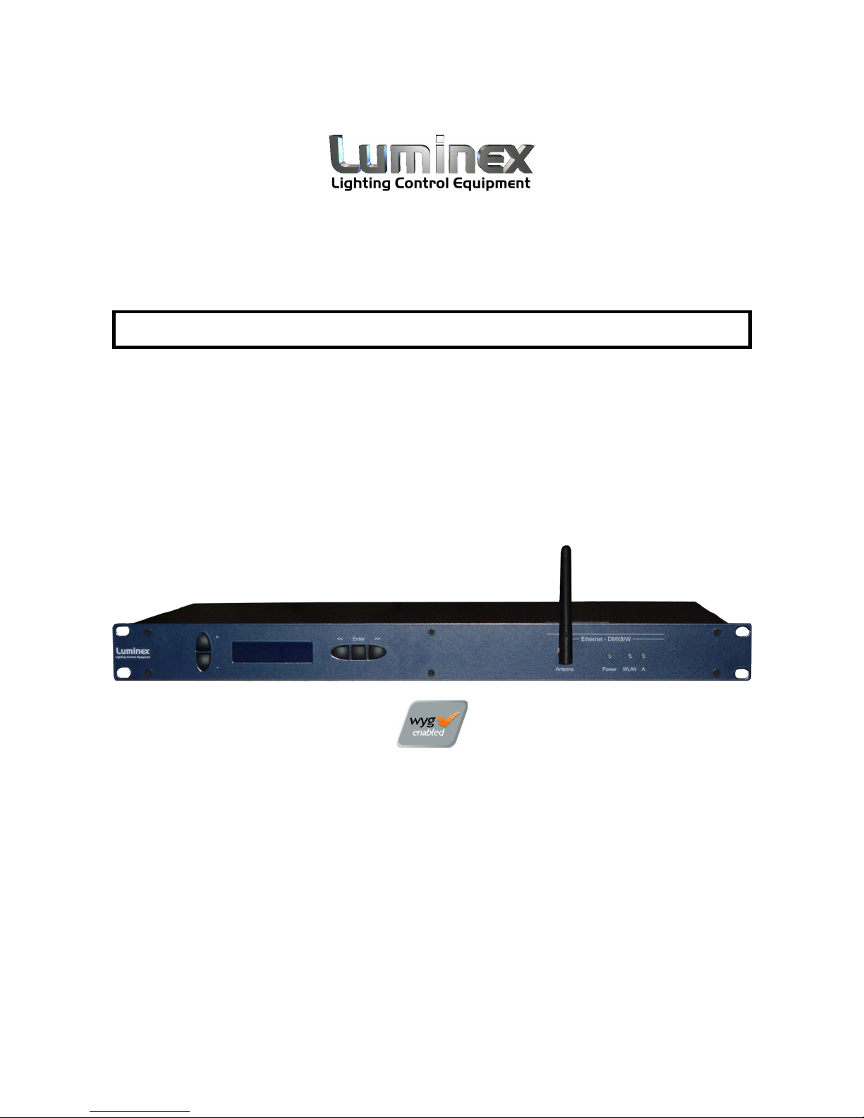
Ethernet - DMX8 / WiFi
User Guide V3.x.x
Page 2

Ethernet - DMX8 / WiFi User Guide V3.x.x
Document eth-dmx8-w_man_v3_lumwifi
Copyright © 2003-2009 .
All rights reserved.
No part of this documentation may be reproduced or transmitted in any form or by any means, electronic
or mechanical, including photocopying and recording, without the prior written permission of Luminex.
The information in this documentation is supplied without warranty of any kind, either directly or
indirectly, and is subject to change without prior written notice. Luminex, its employees or appointed
representatives will not be held responsible for any damages to software, hardware, or data, howsoever
arising as a direct or indirect result of the product(s) mentioned herein.
Issued by:
Publications Department,
Luminex LCE,
Herent 42,
Neerpelt,
B-3910,
Belgium.
Documentation reviewed by Bart Swinnen.
Printed in the EU.
Page 3

Table of Contents
Warranty information........................................................................5
Limited warranty..........................................................................5
Returning under warranty..............................................................5
Freight........................................................................................ 5
General.......................................................................................... 6
Packaging....................................................................................6
Description.................................................................................. 6
Specification................................................................................ 6
Dimensions...............................................................................6
Weight..................................................................................... 6
Electrical.................................................................................. 6
Connectors............................................................................... 6
Environmental...........................................................................7
Connectivity.................................................................................... 8
Rear panel................................................................................... 8
Mains.......................................................................................8
DMX input / output.................................................................... 8
Interface........................................................................................ 9
Front panel.................................................................................. 9
Unlock the node......................................................................10
Reset the node (Out of jail)....................................................... 10
Network configuration..............................................................11
IP setting ...........................................................................11
UDP ports setting.................................................................12
DMX configuration....................................................................13
Outlet route......................................................................... 14
DMX output...................................................................... 14
DMX input........................................................................ 16
Merged DMX input............................................................. 18
Frame rate setting................................................................ 19
Break time setting................................................................ 19
Mark After Break (MAB) time setting.......................................19
DMX output time setting........................................................ 20
Global settings........................................................................21
Recall profile........................................................................ 22
Store profile.........................................................................23
Firmware version ................................................................. 23
Status indication......................................................................24
Web interface................................................................................ 25
Home........................................................................................ 25
Setup........................................................................................ 26
Node 1 & 2............................................................................. 26
DMX Routing........................................................................... 27
Merging Policies :.....................................................................28
Inputs (Local mode)..............................................................28
Inputs (IP Merging)...............................................................31
Page 4

Outputs (IP Merging)............................................................31
Recover channel................................................................... 33
Patch files :.........................................................................35
Network settings..................................................................36
IP Settings..........................................................................36
Global.................................................................................... 37
DMX details......................................................................... 37
Miscellaneous.......................................................................38
Toolbox......................................................................................39
Profile manager....................................................................... 39
Firmware upgrade.................................................................... 40
Wireless........................................................................................41
Wireless basics........................................................................... 41
Installation considerations.........................................................41
Set the Ethernet DMX8/W Wireless device.....................................43
Web Browser:.........................................................................43
Network................................................................................. 45
Wireless settings.....................................................................46
Site Survey............................................................................. 48
Advanced :............................................................................. 49
Firmware upgrade:...................................................................49
Status page............................................................................ 50
Reseting the Ethernet DMX8/W wireless device............................51
Application examples................................................................... 51
Point to point..........................................................................51
Point to multi-point.................................................................. 52
Repeater................................................................................53
Tools :....................................................................................... 55
Checking your computer IP address:..............................................55
Checking the connection .......................................................... 55
Specifications (Wireless Device):................................................56
Additional Documentation................................................................57
Page 4 of 54 Ethernet - DMX8 / WiFi
Page 5

Warranty information
Limited warranty
Unless otherwise stated, your product is covered by a one (1) year parts
and labor limited warranty. It is the owner’s responsibility to furnish
receipts or invoices for verification of purchase, date, and dealer or
distributor. If purchase date cannot be provided, date of manufacture will
be used to determine warranty period.
Returning under warranty
Any Product unit or parts returned to Luminex LCE must be packaged in a
suitable manner to ensure the protection of such Product unit or parts,
and such package shall be clearly and prominently marked to indicate that
the package contains returned Product units or parts. Accompany all
returned Product units or parts with a written explanation of the alleged
problem or malfunction.
Freight
All shipping will be paid by the purchaser. Items under warranty shall have
return shipping paid by the manufacturer only in the European Union.
Under no circumstances will freight collect shipments be accepted. Prepaid
shipping does not include rush expediting such as air freight. Air freight
can be sent customer collect in the European Union.
Warranty is void if the product is misused, damaged, modified in any way,
or for unauthorized repairs or parts.
Ethernet - DMX8 / WiFi Page 5 of 54
Page 6

General
Packaging
• 1 x Ethernet – DMX8 / WiFi
• 1 x 2dBi antenna
• 1 x User guide + CD Rom
Description
The Ethernet - DMX8 / WiFi is an Ethernet node that serves 8 DMX512
outlets, compatible with the ArtNet protocol.
All 8 outlets are conform to the DMX-512A and can be used as input or
output. The Ethernet link is a 10/100BaseT (auto detect) connection on a
Neutrik RJ45 Ethercon connector. All configuration can be done over
Ethernet through a built in website, or by using the controls on the front
end. A bright blue LCD with white text and 5 navigation keys are provided
to control the unit. This all comes in a 19" 1 unit high metal housing.
Specification
Model: Ethernet - DMX8 / WiFi
Manufacturer: LUMINEX Lighting Control Equipment
• Dimensions
482 x 183 x 44 (mm)
19” x 7,2” x 1,75”
Package: 520 x 235 x 50 (mm)
• Weight
2,5 kg
• Electrical
Voltages: 90 – 260 VAC
Frequency: 47 – 63 Hz
Rated power: 20 W
Fuses: 125V, 500mA, Slow blow only (5mm x 20mm)
250V, 315mA, Slow blow only (5mm x 20mm)
• Connectors
1 x Neutrik RJ45 Ethercon connector
8 x Neutrik gold plated 5 pin XLR (female)
1 X RP-SMA antenna connector
• Environmental
Operating temperature: 0 ~ 60°C (32 ~ 140°F)
Page 6 of 54 Ethernet - DMX8 / WiFi
Page 7
Connectivity
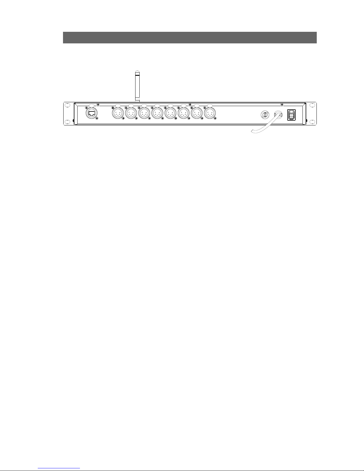
Rear panel
• Mains
The device operates with an AC voltage between 90V and 260V within a
frequency range of 47Hz and 63Hz.
A fixed power lead with lose cable end is directly connected to the device
(no plug/connector). Please use an authorized plug and connect the cores
in the mains lead in accordance with the following scheme:
Green / Yellow: Earth
Blue: Neutral
Brown: Live
!!! This equipment must be earthed !!!
• DMX input / output
8 Neutrik 5 pin gold plated female connectors are provided as outlet (input
or output).
Connector Function
Pin 1 Signal common (0 volt)
Pin 2 Data complement (-)
Pin 3 Data true (+)
Pin 4 Not used
Pin 5 Not used
All outlets are compliant with the DMX512-A timing specification and are
terminated and rebiased.
Ethernet - DMX8 / WiFi Page 7 of 54
Page 8

Interface
Front panel
The front panel interface is provided with 5 navigation buttons and a
bright blue 2 lines, 16 character LCD.
All settings and setup explained in this chapter can also be made by using
the built in web pages. See Web interface chapter at page 24.
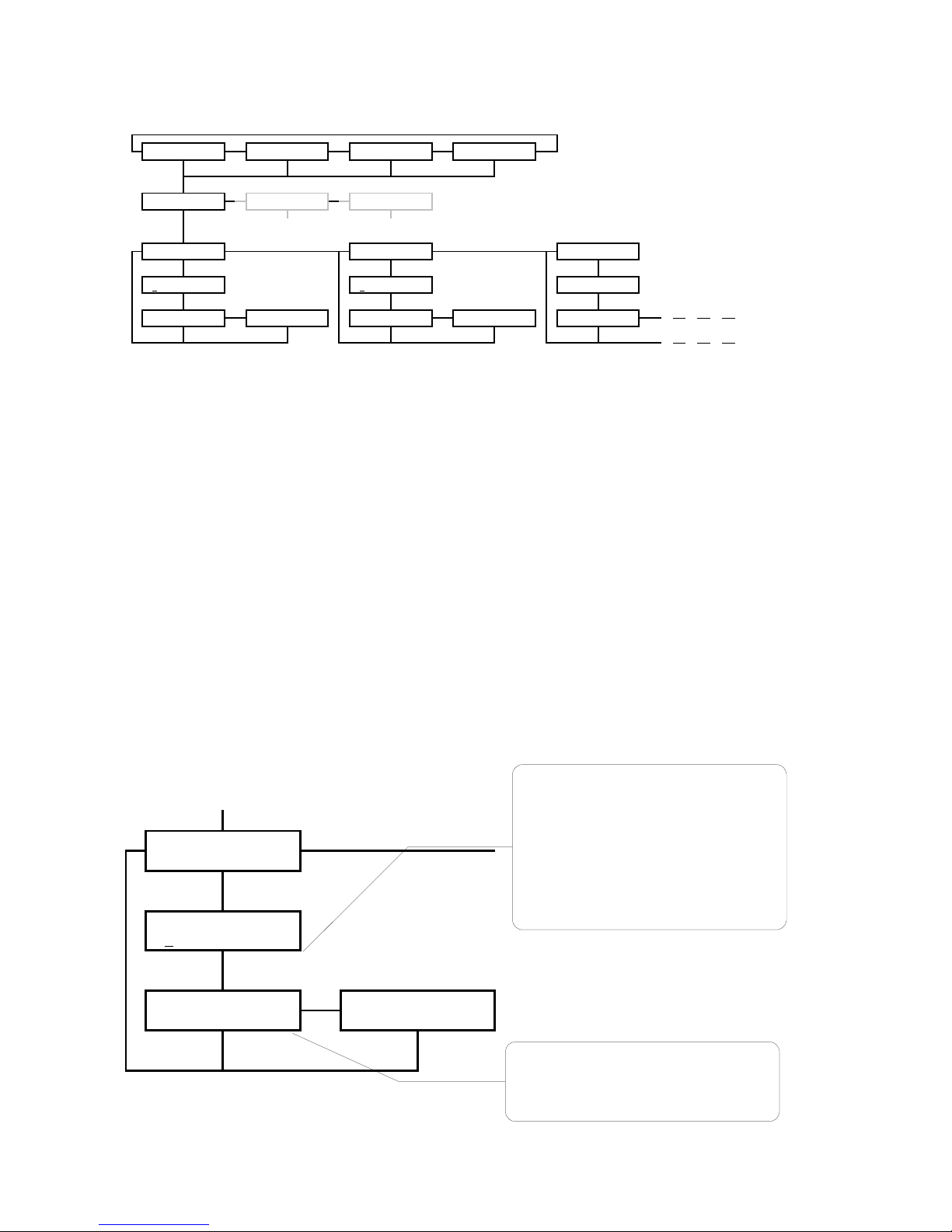
Four indication screens will rotate continuously on the display with an
interval of a few seconds. The unit also returns to these root screens when
no button is pressed for 2 minutes.
You can visualize the screen of your choice by simply pressing the right
arrow button (>>).
Another indication screens sequence is also available by pressing up arrow
button or “+”. This sequence displays all outlets legend and mode. This
can be very useful for a technician who just need to know what is
connected to a dedicated outlet. This sequence is available even if the
node is password protected through Web interface.
Page 8 of 54 Ethernet - DMX8 / WiFi
>> >> >> >>
<< << <<
+ + + +
-
.: Eth-DMX8 :.
ID: 001 >
1:Node 1
2.0.0.2 >
2:Node 2
2.0.0.3 >
Eth 12345678
L ........ >
<<: to navigate left in the menu hierarchy
>>: to navigate right in the menu hierarchy
<<>>: to navigate between character fields
Enter: to move down in the menu hierarchy
or to confirm an edit field
Up/Down: to get out of root screen and enter main menu
-: To change values of edit fields
Up: to navigate up in the menu hierarchy
+: To change values of edit fields
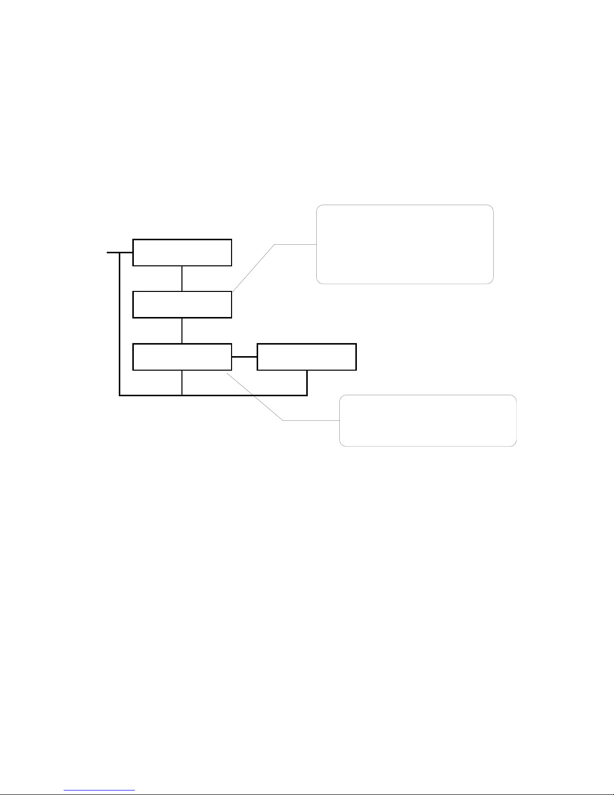
+: To visualize outlet legend and mode sequence
LED indication of network
link for rear ports A – Wireless
device WLAN LED.
Built in Switch
Power LED
Page 9

To get in the configuration menus and to setup the device, press the arrow
down or “-” button.
An arrow left or right (<>) in the screen indicates the possibility to
navigate with the left right buttons of the front end.
● Unlock the node
When the node is set in auto-lock mode or is password protected through
the Web interface, it will automatically lock the front end after 2 min of
inactivity of front end controls. If you try to change something with front
end, the following message “DEVICE LOCKED” will blink.
To unlock the node with no password :
– Hold down up and down arrow button for 2 seconds
– A “HOLD TO UNLOCK” message appears
– “DEVICE UNLOCKED” : the node is unlocked
To unlock the node set with a password :
– Hold down up and down arrow button for 2 seconds
– Password has to be set with left and right buttons, change value with
up and down buttons.
– Press enter to confirm the password=> the node is unlocked
• Reset the node (Out of jail)
This useful function makes it possible to bring the node in a factory
default.
1. Power down the unit.
2. Hold down up, down, left and right buttons all together
3. Power on the node.
4. Wait until “Reboot default” message is displayed
5. Release buttons, then press enter to confirm
6. “FACTORY RESTART !! WAIT !!” is displayed
7. The node is now in a factory default: IP: 2.0.0.2 / 2.0.0.3
Ethernet - DMX8 / WiFi Page 9 of 54
>> >> >> >>
<< << <<
+
-
< 1: IN MRG >
Outlet 1
< 2: IN M CST >
Outlet 2
< 8: OUT >
Outlet 8
Page 10
● Network configuration
IP setting
The device uses ArtNet as protocol to distribute multiple DMX lines over
Ethernet. Because of the ArtNet specification, the number of outlets is
limited to 4 (4 inputs and / or 4 outputs) per node. The Ethernet – DMX8 /
WiFi however has 8 outlets. That is why the device uses 2 IP addresses.
There are virtually 2 ArtNet nodes running on this one device. This allows
us to serve 8 outlets, 4 for every node. Because an ArtNet node is known
by it's IP address on a network, we have to provide 2 unique IP addresses
(IP 1 and IP 2). However, this provides you to the opportunity to run 2
separate networks on the same device.
From Configuration network press Enter to get into Network Config,
Set IP 1. Here you can use the left, right keys to choose to configure IP
1, IP 2 or UDP port. Choose Set IP 1 and press Enter. The IP edit screen
appears with the first digit blinking. The following procedure is similar for
IP 2.
Page 10 of 54 Ethernet - DMX8 / WiFi
With the up down keys you can alter the
value of the blinking edit field.
You can change from edit field by using the
left and right key.
In the remaining fields the value can be
between 0 and 255. You can hold down the
up or down keys to easily set large numbers.
The count will accelerate after a while.
Once the IP is set, press ENTER to go to the
confirmation screen.
In this confirmation screen you can choose
with the left right keys whether you want to
confirm your changes or cancel them.
Press ENTER in the convenient screen to
Confirm or to Cancel the IP setting.
En ter
<<
En ter
En ter
>>
<<
En ter En ter
Network Config
Set IP 1 >
IP 1 Config
2. 0. 0. 2
2. 0. 0. 2
CONFIRM >
2. 0. 0. 2
< CANCEL
>> >> >> >>
<< << <<
+ + + +
-
>> >>
<< <<
+
Ente r
>> >>
<< <<
Ente r Ente r Ente r
Ente r Ente r Ente r
>> >>
<< << <<
Ente r Ente r Ente r Ente r Ente r
.: Eth-DMX8 :.
ID: 001 >
1:Node 1
2.0.0.2 >
2:Node 2
2.0.0.3 >
Eth 12345678
< L ........ >
Configuration
Network >
Configuration
< DMX >
Configuration
< Global Set.
Network Config
Set IP 1 >
Network Config
< Set IP 2 >
Network Config
< Netmask 1 >
IP 1 Config
2. 0. 0. 2
IP 2 Config
2. 0. 0. 3
Netmask 1 Config
255. 0. 0. 0
2. 0. 0. 2
CONFIRM >
2. 0. 0. 2
< CANCEL
2. 0. 0. 3
CONFIRM >
2. 0. 0. 3
< CANCEL
255. 0. 0. 0
CONFIRM >
Page 11
UDP ports setting
The UDP ports are used to indicate the Ethernet ports number on which
the network socket has to listen for ArtNet data. 2 UDP ports are available
on the node, 1 for four universes. These numbers are indicated in Hex
value and the default is 0x1936. These values may only be changed by an
experienced network administrator.
Ethernet - DMX8 / WiFi Page 11 of 54
Use the up down keys to change the value of
every digit separately.
Every digit can be a value between 0 and F
(hexadecimal).
Use the left right keys to change from edit
field.
Once the UDP port is set, press ENTER to go
to the confirmation screen.
In this confirmation screen you can choose
with the left right keys whether you want to
confirm your changes or cancel them.
Press ENTER in the convenient screen to
Confirm or to Cancel the UDP port setting.
> >
En t er
En t er
>>
<<
En t er Ente r
Network Config
< UDP port 1
UDP port 1
0x1936
Port 1: 0x1936
CONFIRM >
Port 1: 0x1936
< CANCEL
Page 12
• DMX configuration
Every DMX outlet can be configured separately as input or output. These
inputs and outputs get a DMX line address on ArtNet. It is possible to
distribute 256 different DMX lines over ArtNet.
The Ethernet – DMX8 / WiFi runs 2 ArtNet Nodes with outlet 1 to 4 on
Node 1 and outlet 5 to 8 on Node 2. Some settings of the DMX outlets are
dependent on the Node setting.
The DMX line address (Universe) on ArtNet is a combination of the outlet's
Subnet and Subswitch. The Subnet divides the possible range of 256
addresses in groups of 16 addresses. Every outlet has one Subnet setting
(from 0x0 – 0xF, 0- 15). And every outlet has a separate Subswitch (from
0x0 – 0xF, 0 – 15). Combined this gives the following result.
The Subnet is the high nibble of the complete address and the Subswitch
is the low nibble of the address.
Outlet 1:
Subnet: 0x2 Outlet 1-> Subswitch: 0xC
Result address: 0x2C
In decimal this would be:
Result = (Subnet x 16) + Subswitch
Result address = (2 x 16 ) + 12 = 44
Happily, if you're not used to work on hexadecimal values, the node allows
you to set you outlet DMX line in decimal value. The corresponding
hexadecimal value will be displayed in brackets.
Example:
Page 12 of 54 Ethernet - DMX8 / WiFi
>> >> >> >>
<< << <<
+ + + +
-
>> >> >>
<< << <<
+
En te r
>> >> >> >>
<< << << <<
+
.: Eth-DMX8 :.
ID: 001 >
1:Node 1
2.0.0.2 >
2:Node 2
2.0.0.3 >
Eth 12345678
< ........ >
Configuration
Network >
Configuration
< DMX >
Configuration
< Global Set.
Firmware Ver.
< 3.0.0
DMX Config
Outlet route >
DMX Config
< FrameRate >
DMX Config
< Break time >
DMX Config
< MAB time >
DMX Config
< Output time
Outlet : 1
Univ: 0 (00)
Page 13

Outlet route
➢ DMX output
To setup an outlet as output, follow the following procedure.
Choose DMX Config, Outlet route press Enter and select the outlet with
the left right keys.
Enable
Yes Enables the outlet
No Disables the outlet
Dir (Direction)
Output Sets the outlet as DMX output
Input Sets the outlet as DMX input
Mode (output)
Single The DMX outlet outputs normal DMX data coming in over ArtNet.
Zero DMX outlet outputs DMX data with all zero values for all 512 channels.
Univ (Universe)
Sets the outlet's DMX line address. ArtNet Hexadecimal value is available in brackets
Ethernet - DMX8 / WiFi Page 13 of 54
Select with up and down keys to enable or to disable the
outlet. When disabled no further configuration is needed.
Select INPUT or OUTPUT direction of DMX outlet
Set the DMX output mode: SINGLE or ZERO
Select the DMX line address. The combined ArtNet
universe address is shown in brackets. This is the
combination of the outlet's subnet and subswitch.
Set merging of ArtNet DMX packages of different IP
sources on or off.
When IP merging enabled you can choose between
HTP, LTP or CST (Custom mode).
>> >> >>
<< << <<
+
En te r
>> >>
<< <<
En te r
NO
YES Enter
+
-
OUTPUT Enter INPUT Enter
En te r
En te r
En te r
>>
<<
En te r E nt e r
DMX Config
Outlet route >
DMX Config
< FrameRate
DMX Config
< Break Time
DMX Config
< MAB Time
DMX Config
Outlet : 1 >
DMX Config
< Outlet : 2 >
DMX Config
< Outlet : 8
Outlet : 1
Enable : YES
Outlet : 1
Dir: OUTPUT
Outlet : 1
Dir: INPUT
Outlet : 1
Mode : SINGLE
Outlet : 1
Univ: 0 (00)
Outlet : 1
IP Merging: OFF
Save setup ?
CONFIRM >
Save setup ?
< CANCEL
Page 14

IP Merging
OFF Disable the IP merging feature
HTP Merge 2 ArtNet streams set with same universe address; All channels
outputted from that outlet will result of a Highest Take Precedence policy
between the two first registered ArtNet sources.
LTP Merge 2 ArtNet streams set with same universe address; All channels
outputted from that outlet will result of a Last Take Precedence policy
between the two first registered ArtNet sources.
CUSTOM Need the use of a Web browser. Create here a complete softpatch, select
the 2 ArtNet sources IP addresses and universe addresses to merge. You
can affect each kind of merging policy (HTP, LTP, Backup, S1 only, S2
only..) on each channel of the selected outlet. You can also set here the
Trigger channel to remotely change theses policies through DMX.
Page 14 of 54 Ethernet - DMX8 / WiFi
Page 15
➢ DMX input
To setup an outlet as input, follow the following procedure.
Choose DMX Config, Outlet route press Enter and select the outlet with
the left right keys.
Enable
Yes Enables the outlet
No Disables the outlet
Dir (Direction)
Output Sets the outlet as DMX output
Input Sets the outlet as DMX input
Ethernet - DMX8 / WiFi Page 15 of 54
En ter
>> > > > >
< < < < <<
+
En ter
>> >>
< < < <
En ter
NO
YES Enter
+
-
INPUT Enter
+
-
En ter
En ter
+
-
En ter
En ter
En ter
>>
< <
DMX Config
Outlet route >
DMX Config
< FrameRate >
DMX Config
< Break Time >
DMX Config
< MAB Time >
DMX Config
Outlet : 1 >
DMX Config
< Outlet : 2 >
DMX Config
< Outlet : 8
Outlet : 1
Enable : YES
Outlet : 1
Dir: OUTPUT
Outlet : 1
Dir: INPUT
Outlet : 1
Mode : NORMAL
Outlet : 1
Mode : MERGE
Outlet : 1
Univ: 0 (00)
Outlet : 1
IP Merging: OFF
Outlet : 1
IP Merging: BCK
Outlet : 1
Backup ms: 400ms
Outlet : 1
Recover: AUTO
Save setup ?
CONFIRM >
Save setup ?
< CANCEL
Set the DMX input mode: NORMAL or MERGE
Select the DMX line address. The combined
ArtNet universe ad dr e ss is s h o w n i n
brackets. This is the combination of the
outlet's subnet and subswitch.
Page 16

Mode (input)
Normal The DMX outlet works as a normal DMX input putting data on ArtNet.
Merge The outlet will be merged with the next outlet. This option is only
available for outlet 1, 3, 5 and 7. When this mode is chosen, the next
outlet is automatically set as input. Merge policies can be set by
configuring the next outlet. (see Merged DMX input)
Univ (Universe)
Sets the outlet's Subswitch to complete the complete universe, or DMX line address
of the normal input or the merge result.
IP Merging
Off The DMX outlet works as a normal DMX input putting data on ArtNet.
Bck The outlet act as networked backup input. It will function as a input
backup of the main ArtNet source set with the same universe address.
When invalid or no DMX is received from the primary ArtNet source, this
outlet will automatically take over. The primary source takes over again
as soon as valid data is available again
Backup ms
Set here the time within the node as to wait before switching to the backup outlet
(from 400 to 9999ms) in case of primary ArtNet source stream failure.
Recover
Auto If the failed ArtNet stream is back again on the network, the node will
switch back automatically to this previous ArtNet source, and thus
disable the backup outlet.
Manual The node will not switch back automatically to the previous ArtNet
stream. You'll have to switch yourself to the previous ArtNet stream by
using the recover channel patched in the enabled trigger universe. See
page 28
Page 16 of 54 Ethernet - DMX8 / WiFi
Page 17
➢ Merged DMX input
If one of the odd outlets (1, 3, 5 or 7) is set as merged input, then the
corresponding even outlet (2, 4, 6 or 8) is automatically set as input. For
this input you have to configure the merging policy and start address
offset (for HTP and LTP only).
Enable
Yes Enables the outlet
No Disables the outlet
Mode (merged)
HTP Merges the channels from this outlet starting at the offset into the
previous outlet input, using Highest Takes Precedence (HTP) policy. The
highest value of 2 merged channels will be used.
LTP Merges the channels from this outlet starting at the offset into the
previous outlet input, using Latest Takes Precedence (LTP) policy. The
latest changed values will end up in the merge result.
BACKUP This outlet will function as a input backup of the previous outlet. When
invalid or no DMX is received on the primary (previous) outlet, this outlet
will automatically take over. The primary outlet takes over again as soon
as valid data is available again.
CUSTOM This mode requires the use of a Web browser. It is the most complete
one as all policies listed above are available for each channel. A complete
softpatch can thus be created by using the table available through the
built-in Web server. See page 28 for more details.
Offset
Sets the offset address of where the merging of the second outlet has to start. This
option is not applicable in BACKUP and mode.
Ethernet - DMX8 / WiFi Page 17 of 54
Set merge policy: HTP, LTP, BACKUP or
CUSTOM
Set the channel offset from which start
address this outlet has to be merged in
with the previous outlet (1)
En te r
> > > > > >
<< << < <
+
En te r
> > > >
<< <<
En te r
N O
YES Enter
En te r
En te r
> >
<<
En te r Ent e r
DMX Config
Outlet route >
DMX Config
< FrameRate >
DMX Config
< Break Time >
DMX Config
< MAB Time >
DMX Config
Outlet : 1 >
DMX Config
< Outlet : 2 >
DMX Config
< Outlet : 8
Outlet : 2
Enable : YES
Outlet : 2
Mode : HTP
Outlet : 2
Offset: 001
Save setup ?
CONFIRM >
Save setup ?
< CANCEL
Page 18

Frame rate setting
The frame rate setting determines the DMX refresh rate. The refresh rate
is set for all outlets similar. The frame rate can be set from 20 to 40 FPS
(Frames Per Second).
Break time setting
The break time of the DMX signal can be set from 92 – 352 us. This is the
idle time between 2 DMX packets of 512 channels.
Mark After Break (MAB) time setting
The MAB time of the DMX signal can be set from 12 – 88 us. This is the
time after the idle time to indicate a new DMX packet start.
Page 18 of 54 Ethernet - DMX8 / WiFi
>> >> > > >> > >
<< << < < << < <
+
Ent er
Ent er
>>
<<
Ent er En ter
DMX Config
< Outlet Route >
DMX Config
< FrameRate >
DMX Config
< Break time >
DMX Config
< MAB time >
DMX Config
< Output time
DMX Config
Break : 210 uS
Save setup ?
CONFIRM >
Save setup ?
< CANCEL
En te r
>> >> >> >>
<< << << <<
+
En te r
En te r
>>
<<
En te r En te r
DMX Config
Outlet route >
DMX Config
< FrameRate >
DMX Config
< Break Time >
DMX Config
< MAB Time >
DMX Config
< Output Time
DMX Config
FPS : 36
Save setup ?
CONFIRM >
Save setup ?
< CANCEL
Use Up and Down keys to change the DMX
frame rate setting (20-44 fps).
Use Up and Down keys to change the
DMX break time setting (92 -352
uS).
>> >> > > >> > >
<< << < < << < <
+
Ent er
Ent er
>>
<<
Ent er En ter
DMX Config
< Outlet Route >
DMX Config
< FrameRate >
DMX Config
< Break time >
DMX Config
< MAB time >
DMX Config
< Output time
DMX Config
MAB : 50 uS
Save setup ?
CONFIRM >
Save setup ?
< CANCEL
Use Up and Down keys to change the DMX
MAB setting (12-88 uS).
Page 19

DMX output time setting
The DMX output time is used to set the amount of time an output has to
transmit its latest received DMX data from ArtNet onto the DMX outlets.
The output time can be set continuously or from 1 – 10 minutes.
Ethernet - DMX8 / WiFi Page 19 of 54
>> >> >> > >
<< << < < <<
+
Ent er
Ent er
>>
<<
Ent er En te r
DMX Config
< FrameRate >
DMX Config
< Break time >
DMX Config
< MAB time >
DMX Config
< Output time
DMX Config
Output: Contin.
Save setup ?
CONFIRM >
Save setup ?
< CANCEL
Use Up and Down keys to change the DMX
output time setting (continuously or 1-10
minutes).
Page 20

• Global settings
The global settings contains the Profile Manager. Here you can recall and
save complete routings and network settings into a profile.
Space is provided to hold 40 different profiles. Already 11 most used
profiles are provided with the firmware.
Profile Description
1 Default All outlets as disabled output
2 1 in + 7 out 1 input at 0(00) and 7 outputs starting at 1(01) to 7(07)
3 All out 0 All outlets as single output starting at 0(00) to 7(07)
4 All out 8 All outlets as single output starting at 8(08) to 15(0F)
5 All in 0 All outlets as normal input starting at 0(00) to 7(07)
6 All in 8 All outlets as normal input starting at 8(08) to 15(0F)
7 1.7 Hub 1 input and 7 output all at 0(00)
8 2x1.3 Hub 2 inputs and 3 outputs for every input at 0(00) and 1(01)
9 4 x MergeHtp 4 x 2 merged inputs in HTP mode at 0(00) to 3(03)
10 4 x MergeLtp 4 x 2 merged inputs in LTP mode at 0(00) to (03)
11 4 x Backup 4 x 2 backup inputs at 0(00) to 3(03)
Page 20 of 54 Ethernet - DMX8 / WiFi
>> >> >> >>
<< < < < <
+ + + +
-
>> >> >>
<< < < < <
+
En te r
>>
< <
+
.: Eth-DMX8 :.
ID: 001 >
1:Node 1
<2.0.0.2 >
2:Node 2
<2.0.0.3 >
Eth 12345678
< ........ >
Configuration
Network >
Configuration
< DMX >
Configuration
< Global Set.
Firmware ver.
< 3.0.0
Profiles
Recall >
Profiles
< Store
Page 21

Recall profile
To recall a profile, apply the following procedure.
Choose Global Set., Profiles Recall and press Enter.
Choose the profile you want to recall. All empty profiles are marked like
this: “--Empty--”
When recalling an empty profile, no changes will occur. The menu won't
ask to confirm anything, it will only exit the recall menu.
When a valid profile is chosen the device will ask to recall network settings
or not. When network settings are recalled, the IP and UDP port settings
will be modified as well to default values. So if you do not want to touch
you're already configured network setting say NO here.
Ethernet - DMX8 / WiFi Page 21 of 54
En t e r
>>
<<
+
En t e r
En t e r
En t e r
>>
<<
En t e r En t e r
Profiles
Recall >
Profiles
< Store
1. Default
2. 1 in + 7 out
Recall Network
Settings? NO
Recall 1 ?
CONFIRM >
Recall 1 ?
< CANCEL
Use Up and Down keys to select the profile
you want to recall.
Use Up and Down keys to decide to recall
network setting as well, or not.
Page 22

Store profile
To store a profile, apply the following procedure.
Choose Global Set., Profiles Store and press Enter.
Select an empty profile to store the profile, or choose the profile you want
to overwrite.
When an empty profile is chosen, the device will ask to edit the profile
name. By default it will come up with “profile “ followed by the profile
number.
When an already used profile is chosen the device will come with the
existing name. You can edit the name or just go on by pressing enter.
When you want to save over an existing profile, you'll obviously see
“OVERWRITE” instead of “STORE” in the confirm window. Be aware that
overwritten profiles can't be recovered in any way.
Firmware version
This screen quickly display the firmware version running on the node.
This can be useful to check if you're running the latest version.
Visit our Web site to download the latest firmware : www.luminex.be
Page 22 of 54 Ethernet - DMX8 / WiFi
En t e r
>>
<<
+
En t e r
En t e r
En t e r
>>
<<
En t e r E nter
Profiles
Recall >
Profiles
< Store
12. --Empty--
13. --Empty--
Store Profile
12.Profile 12
Store 12 ?
CONFIRM >
Store 12 ?
< CANCEL
Use Up and Down keys to select
an empty profile to store in or a
used profile to overwrite
To edit the name of the profile,
use the Up and Down keys to
change the character And use the
Left and Right keys to change the
edit field.
>> >> >> >>
<< << <<
+ + + +
-
>> >> >>
<< << <<
.: Eth-DMX8 :.
ID: 001 >
1:Node 1
<2.0.0.2 >
2:Node 2
<2.0.0.3 >
Eth 12345678
< ........ >
Configuration
Network >
Configuration
< DMX >
Configuration
< Global Set.
Firmware ver.
< 3.0.0
Page 23

• Status indication
Four indication screens will rotate continuously on the display with an
interval of a few seconds. The unit also returns to these root screens when
no button is pressed for 2 minutes.
One of these screens shows the status of the configured outlets.
Screen Description
There is no outlet configured as input and there is no
outlet outputting DMX data. All outlets are showing _
Outlet 1 is configured as a normal input. The status
indication on outlet 1 will continuously change between
., i and I
Outlet 1 is configured as Merged input together with
outlet 2 in Htp mode. The status of outlet 1 will
continuously change between ., m a n d M indicating
MERGE.
The status of outlet 2 will continuously change
depending the mode of the merging:
Htp: ., h and H
Ltp: ., l and L
Backup: ., b and B
Custom: ., c and C
Outlet 1 is configured as a single (normal) output. The
status indication on outlet 1 will continuously change
between ., o and O
Outlet 1 is configured as a zero output (continuously
outputting DMX zero values for all 512 channels). The
status indication on outlet 1 will continuously change
between ., z and Z
Ethernet - DMX8 / WiFi Page 23 of 54
Eth 12345678
< ________ >
Eth 12345678
< i....... >
Eth 12345678
< mh...... >
Eth 12345678
< o....... >
Eth 12345678
< mb...... >
Eth 12345678
< ml...... >
Eth 12345678
< z....... >
Eth 12345678
< mc...... >
Page 24

Web interface
Home
The complete device can be configured from an intuitive web interface.
You just have to browse to one of the IP addresses mentioned in the root
screen sequence.
Make sure that you computer, you use to browse, is setup in the correct
network address range (IP 2.x.x.x or 10.x.x.x and subnet 255.0.0.0).
When you're not using a complete network setup (Ethernet switches,
hubs, routers, WLAN, ...), you can also use a cross Ethernet cable to
directly connect to one unit.
After all connections and setup on the computer are completed, open your
favorite web browser and enter the IP address you want to reach in the
URL field.
Http://2.0.0.2/
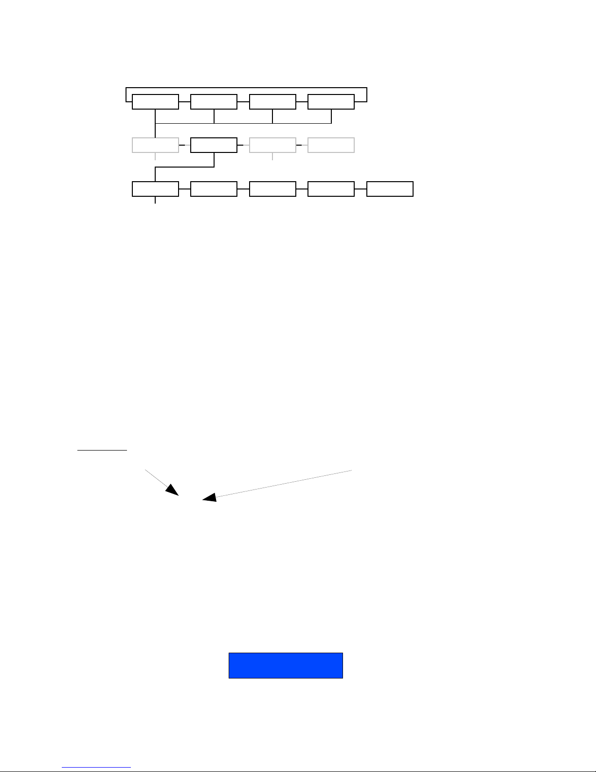
You'll end up at the status page of the device. This page has a complete
overview of the device settings.
The overview shows the actual DMX and network setting / routing of the
complete device.
Page 24 of 54 Ethernet - DMX8 / WiFi
Navigation Bar
Actual DMX routing
Actual Global settings
Actual Network settings
Page 25

Setup
Choose one of the items in the sub menu to setup the device.
Once in a setup page, help is available on almost every field title. Just
click on the question mark next to the topic. A pop up frame will display
the overall information of each term displayed on the Web interface.
● Node 1 & 2
To setup node 1 or 2 click on the appropriate sub menu item in the Setup
navigation bar (Node 1, Node 2).
Node 1 is to setup outlet 1 to 4 and node 2 to setup outlet 5 to 8. This is
indicated on top of the page.
This is the one of the main settings page. You can setup every single
outlet of the node 1 , as input or output. Select the outlet's direction,
mode and universe. Here you can also change the IP address, Netmask,
port and the ArtNet short and long name indication.
Same settings are available for outlets 5 to 8 by clicking on “Node 2” in
the left navigation menu.
Ethernet - DMX8 / WiFi Page 25 of 54
Page 26

● DMX Routing
To better understand the use of all features, let's define each category of
this menu:
Direction : Set the direction you need to the outlet, either Input or
Output. Depending your selection, some features won't be available in the
other categories.
Universe : Select the universe number. The left column number
represents the decimal value, the right column number the Hexadecimal
one. Setting the universe number through Web interface avoids the user
to set Subnet and subswitch settings separately.
Mode : According to the direction you set on the outlet, this menu offers
several mode :
Input : Disabled : Outlet is disabled, better for node performance.
Normal : Outlet set as normal input
Merge : Allow to merge 2 DMX streams.
When an odd outlet is configured as a merged input (1,3,5,7), the
corresponding outlet (2,4,6,8) will be automatically set as input as well.
Output : Disabled : Outlet is disabled, better for node performance.
Zero : Send all channels with a zero value (for maintenance
only)
Single: Normal output.
IP Merging : This special feature allows you to merge 2 different DMX or
Artnet streams through the network. The merging policy will be mainly
applied on the DMX Output, except for IP backup.
Legend : Set a legend to the outlet, useful to remind yourself what's
connected to that outlet.
Unicast : Artnet is a broadcast protocol, which means that each packet
sent from a single source will be received by all actives equipment on the
network. Unicast provides you to cast you data to a selected IP address,
resulting in a lower use of bandwidth.
All setting that are not applicable for the actual setting will be grayed out
or marked as N/A (Not Applicable).
Page 26 of 54 Ethernet - DMX8 / WiFi
Page 27

● Merging Policies :
The Ethernet-DMX 8 firmware offers enhanced merging policies that fits
to all kind of setup, even the most complex one !
4 available merging policies can be applied on your DMX network, in 2
main setup categories :
Local merging : 2 different DMX streams are merged on the same
physical device (Node). The merging policy will be mainly set on Inputs.
IP Merging : This special feature allows you to merge 2 different DMX or
Artnet streams through the network. The merging policy will be mainly
applied on the Output, except for IP backup.
Available policies :
– HTP : Highest Take Precedence; Commonly used to merge dimmer
channels
– LTP : Latest Take Precedence; Better suited when using moving lights
– Backup : set one of the 2 outlets as a backup input
– Custom : This is the most complete and efficient policy. This mode
offers you to choose what policy to apply for each channel of each
universe, and also to create a complete custom soft patch. By more,
the merging policy can be remotely triggered by DMX.
The available policies differs if you use either inputs or outputs :
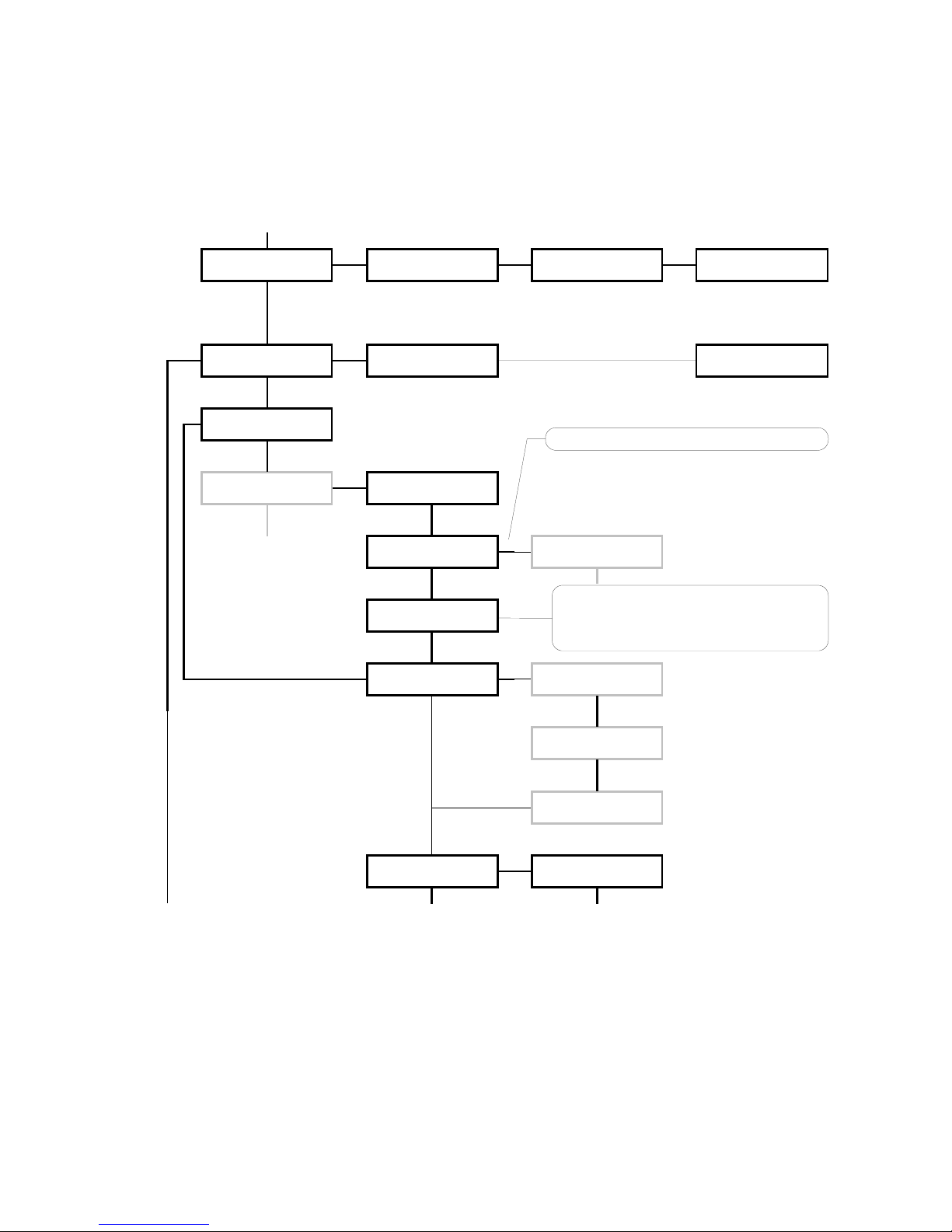
Inputs (Local mode)
Direction Universe Mode
Outlet 1 Input 0(00) Merge
Outlet 2 Input Ch1 HTP, LTP, Backup, Custom
In this example, the selected mode is “Merge”. The second outlet will
automatically be set as a merged input. You will not be able to configure a
universe address for the second outlet, as the merged result will end at
the universe address of the first outlet (primary input). Instead of
Ethernet - DMX8 / WiFi Page 27 of 54
Illustration 1: Local DMX merging
Page 28

universe you will be able to set the starting DMX channel address (1-512).
This indicates from which channel address the second input has to be
merged in. This offset is only available when using HTP or LTP policies.
Those rules will be applied on all channel of the universe.
If you choose “Backup”, a small blue icon will appears on the left side of
“Outlet 2” label; then click on it, a pop up frame appears :
This menu lets you choose the backup time (from 400 to 9999ms). This
time represents the delay from which the node will automatically switch to
the backup outlet when invalid or no DMX is received anymore on the
primary outlet.
Tick the box if you want the node to auto-recover as soon as valid data is
available again on primary connector.
If you tick off the box, you will have to enable the trigger universe and
select a recover channel (page Error: Reference source not found).
If you choose “Custom” policy, a small blue icon will also appear on the
left side of “Outlet 2” label; then click on it, a new pop up frame appears :
Page 28 of 54 Ethernet - DMX8 / WiFi
Illustration 2: DMX Input backup merging
Page 29

Click on “Show Table” button to see the complete soft patch available for
this outlet.
– Offset S1 & S2 : Enter a value for the desired offset of the starting
channel for outlets 1 or 2; example, for channels 1 to start on the third
channel, enter 3.
– From – To : this range let you quickly set the policy you need on the
channel range of your choice. example, if you need HTP policy on
channels 23 to 145, enter 23 in the “From” field and “145” in the “To”
field. Then select the HTP policy in the “Mode” drop down list, then
press “Set Default Mode”.
– Notice that following policies are available for each channel:
Zero, HTP, LTP, S1 only (Source 1 only), S2 only (Source 2
only), S1 as Backup (Source 1 as backup), S2 as Backup
(Source 2 as Backup).
The left column represent the resulting universe channel number
streamed to the network. S1 column represents Source 1 channels and S2
column source 2 channels. It's thus easy to understand that you can
create your own soft patch by entering the channels of your choice in one
of theses column.
Once your patch is created, click submit to close the window, then click
submit again on the node page to record your settings.
Ethernet - DMX8 / WiFi Page 29 of 54
Illustration 3: Custom DMX input merging
Page 30

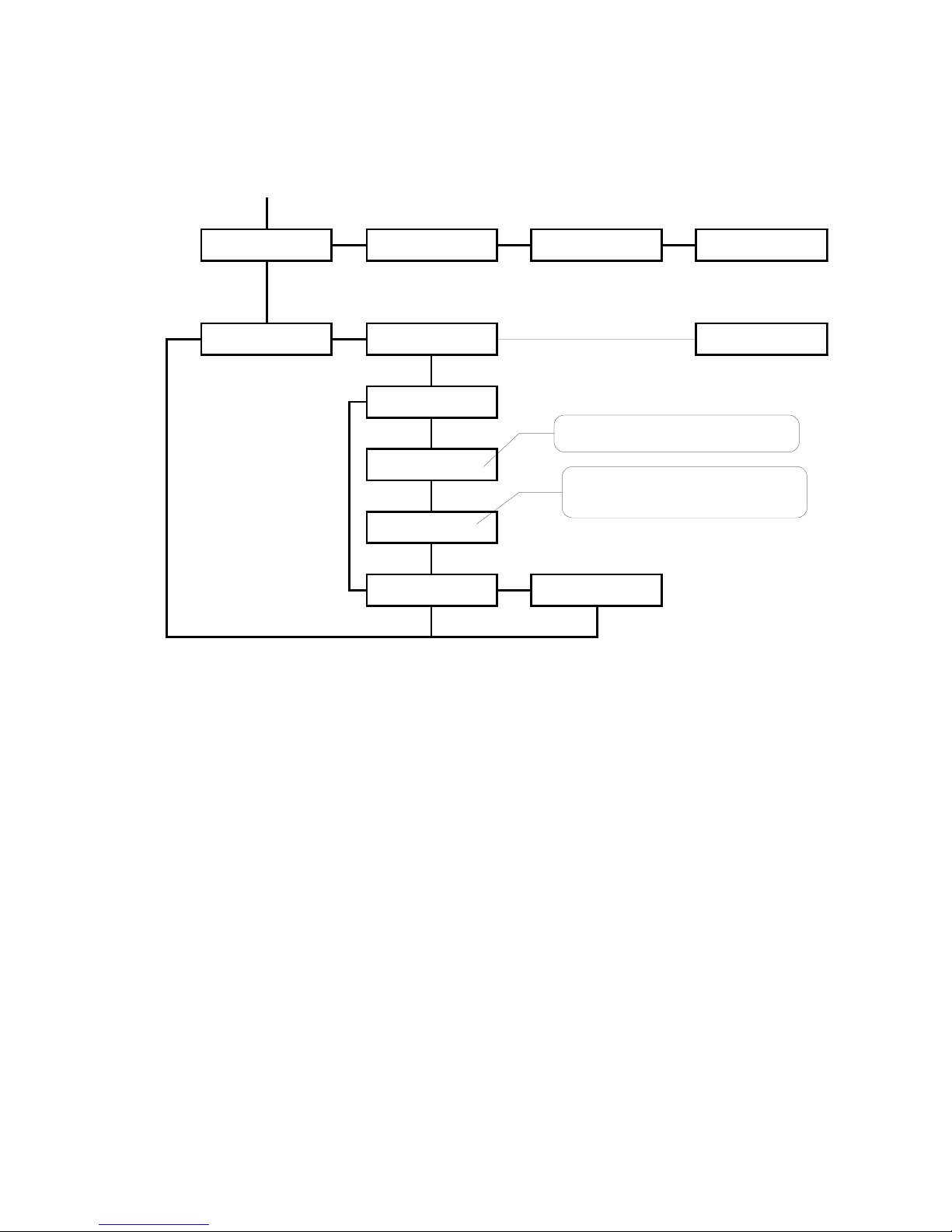
Inputs (IP Merging)
Direction Universe Mode IP Merging
Outlet 1 Output 0(00) Single Disabled
Outlet 2 Output 1(01) Single Disabled
Outlet 3 Input 0(00) Normal Backup
Outlet 4 Input 0(01) Normal Backup
This mode can be very useful in such an application.
The right side lighting desk is used as a backup desk on stage. This means
that the right side node will automatically switch to theses outlets if no
ArtNet packets are available on the selected universes (in that case
universe 0 and 1). Select your backup time in the small pop up frame by
clicking the left blue icon, then submit your changes.
Outputs (IP Merging)
Direction Universe Mode IP Merging
Outlet 1 Output Single HTP, LTP,
Custom
Outlet 2 Output Single HTP, LTP,
Custom
Outlet 3 Output 2(02) Disabled
Outlet 4 Output 3(03) Disabled
This mode can be very useful in the case of 2 control sources located in
different places in the network wants to control the same DMX device in
the same time.
Page 30 of 54 Ethernet - DMX8 / WiFi
Illustration 4: IP Merging
Illustration 5: Output IP merging
Page 31

In this setup, the right lighting software (S2) is used in the same time as
the left lighting desk (S1). Both streams are merged through the final
output on the right node.
The IP Merging mode provides the following policies when an outlet is set
as output:
– HTP, for all outlet channels
– LTP, for all outlet channels
– Custom, to create a complete soft patch, to set merging policy for
every single channel by IP source and to use the enhanced trigger
system. Once Custom is selected, the universe number will disappear
in the outlet's universe setting row.
If you choose “Custom”, click on the blue icon left sided to the “Outlet”
label. A pop up frame appears:
You can find in this pop up frame similar features as when using the
Ethernet - DMX8 / WiFi Page 31 of 54
Illustration 6: DMX Output custom IP merging
Page 32

custom merging on outlets set as inputs (page 28).
The main difference is about the following points :
– IP Source 1 & 2 : Here you can enter the 2 IP addresses assigned to
your 2 control source. In case you don't know one of your source IP
address, simply enter 0.0.0.0 in the address field.
– Universe : Here you can select the universes number streamed by
your control source. This feature is very useful if the 2 sources don't
use the same universe number.
– Trigger channel. This feature allows you to remotely change the
merging policy of one or several dedicated channels through a single
DMX value. From anywhere on the network, you can by example swap
from a “LTP” merge to a “S2 only” policy simply by using a different
DMX trigger channel value. Enter here the DMX channel you want to
use to remotely takeover control of the merging rule. Once you've
selected that channel, you'll need to reach the” Global” web page of the
node to enable and select your Trigger universe. You'll also need to
patch or assign a DMX trigger channel to your control source; here is
the DMX chart of the Luminex DMX trigger channel :
0 - 7 Do nothing
8 - 15 Zero out
16 - 23 HTP merge
24 - 31 LTP merge
32 - 39 Source 1 only
40 - 47 Source 2 only
48 - 111 Reserved
112 - 119 Source 1 as backup
120 - 127 Source 2 as backup
128 - 255 Do nothing
Recover channel
If you have set one of a node outlet in IP backup mode, the node will
swap automatically to this outlet in case of DMX failure from the primary
source. Once the primary source is back again available, the node will
automatically swap back to that source if set in Auto-recover mode. We all
know that it can be useful to decide when to swap back to the primary
source (booting time of the desk + loading the right cue in case of desk
failure). Tick off the auto-recover box in the pop up window if you decide
to work in manual recover mode. Then you'll have to enable the trigger
universe in the “Error: Reference source not found” Web page and choose
a recover channel. You now have the opportunity to choose to recover
whether each outlet one by one or all outlet in one shot.
Page 32 of 54 Ethernet - DMX8 / WiFi
Note :Never forget if you control the trigger
channel from more than one source to
press “Do nothing” once you've selected
the desired value. Indeed, if you send
2 different values from 2 different sources
for the trigger channel, the node won't stop
swaping between those values, what results
in a big slowing down of the node processing
power.
Page 33

Here is the Luminex recover channel DMX chart :
0 - 7 Do nothing
8 - 15 Recover outlet 1
16 - 23 Recover outlet 2
24 - 31 Recover outlet 3
32 - 39 Recover outlet 4
40 - 47 Recover outlet 5
48 - 55 Recover outlet 6
56 - 63 Recover outlet 7
64 - 71 Recover outlet 8
72 - 79 Recover all outlets
80 - 255 Do nothing
Patch files :
All those soft patches can be recorded or loaded from or to the node by
using “Load Patch” or “Export patch” buttons. Luminex node recognize .txt
files. These are “TAB” separated files which can be edited using
spreadsheet software (Excel, OO Calc,...)
Ethernet - DMX8 / WiFi Page 33 of 54
Page 34

Network settings
IP Settings
You can enter here the desired ArtNet IP address and Netmask you want
to use. If you're not confident with ArtNet IP setting, tick the “ArtNet
compliant?” box for the node to warn you in case of mistake. ArtNet IP
addresses usually looks like 2.x.x.x or 10.x.x.x.
You're not obliged to work with ArtNet IP addresses. If you wish to work
with usual IT IP addresses as 192.168.x.x, there's no problem for you to
set such address on the node. Please remember that your node will thus
not be visible on the network from devices set with conventional ArtNet IP
addresses (2.x.x.x or 10.x.x.x).
The Port field allows you to change the UDP port used on the network to
transmit your UDP ArtNet packets. Luminex recommend no to change this
value.
Node identification :
Enter here a small and long name to easily identify your node on the
network through a Web interface, ArtNet compliant softwares or Luminex
LumiNet monitor.
Page 34 of 54 Ethernet - DMX8 / WiFi
Page 35

• Global
Some global settings can be altered by clicking Global in the Setup sub
menu. Device Settings
Here you can change the device's ID number which is indicated on
LumiNet monitor.
You can also enable the Trigger universe to remotely control your merging
policy through any DMX source. The node will listen to the specified
universe entered in the universe field.
You can set your Recover channel if you use the manual recovery mode
(page 28, 32).
DMX details
The DMX frame rate setting for all outlets. This can be set from 20 to 44
frames per second.
DMX Break time can be set from 92 – 352 us
DMX Mark After Break (MAB) time can be set from 12-88 us
DMX Output time can be set to 1 – 10 minutes or continuously. This time
sets how long an output remains outputting it's last DMX levels after no
valid DMX packet came in for that particular universe on ArtNet.
Ethernet - DMX8 / WiFi Page 35 of 54
Page 36

Miscellaneous
This part is about security and warnings :
– Verbose level : Select if you want to see error messages on the front
end LCD or the Web interface.
– Lock Mode: select the security level you want to be applied on your
Ethernet-DMX8 /W front end. Auto lock will force the Node to lock all
wheels encoders and switches after 2 minutes of front end inactivity.
Password protected mode will guide you to set a password into the
“locking code” field. Once the node is locked, you'll have to enter the 4
digit password through front end buttons or through Web interface
password field.
Read the “Unlock the node” chapter to see the complete procedure.
Page 36 of 54 Ethernet - DMX8 / WiFi
Page 37

Toolbox
When clicking on Tools in the navigation bar, a sub menu appears. Choose
one of the items in the sub menu.
• Profile manager
The profile manager is able to store 40 profiles. All profiles are stored on
the device.
A preview of the complete configuration stored in a profile is shown when
a profile is selected from the drop down list. When an empty profile is
selected, no preview will be shown.
Once a profile is selected you can choose to recall it, to save actual
settings as a profile, or to delete the profile.
When recalling a profile, an other page will appear to ask whether to recall
your network settings as well or only the outlet routings.
When saving a profile a next page will ask you to fill in a profile name.
Ethernet - DMX8 / WiFi Page 37 of 54
Export profile
Download link to save
selected profile
Import profile
To upload a stored profile
from PC or laptop
Page 38

• Firmware upgrade
The firmware upgrade page allows you to select a downloaded firmware
file and upload it to the device.
This page shows the actual firmware version running on the unit below the
file upload field.
The latest firmware file can always be downloaded from the Luminex web
pages.
Http://www.luminex.be
To install the firmware on the Ethernet-DMX8 / WiFi follow these steps:
1. Download the .zip file and save it on your hard disk.
2. Extract the .zip file.
3. Please read the "ChangeNote.txt" for latest release changes.
4. Browse to the device its IP address with your favorite web browser.
5. Click Toolbox -> Firmware upgrade.
6. Brows e to the e xtracted upgrad e fil e on your har d dis k
(upgrade_eth_dmx8w.tgz).
7. Select the file and press on the "Upgrade" button.
8. The upgrade file will be sent to the device.
9. Wait until the device has rebooted.
10.Enter the IP number of the device in your browser and check at
Toolbox -> Firmware upgrade if the current version is set to the
right version number. If the number is the same as mentioned with
the file than the upgrade has succeeded.
Page 38 of 54 Ethernet - DMX8 / WiFi
Page 39

Wireless
The Ethernet DMX8/W is the wireless edition of the Ethernet DMX8
gateway, allowing you to transport your ArtNet DMX stream through a
802.11a/b/g wireless link, and to connect other 802.11 compatible
devices such as PDA or computer to your Wireless DMX network.
The Ethernet DMX8/W comes with an on-board wireless device which
offers you multiple configurations (access point, client) depending of your
needs.
The Ethernet DMX8/W offers you all the Ethernet DMX8 features plus the
ability to transfer your data wireless, meaning you have access to the
merging, spliting, backup features on a wireless tool !
System requirements for configuration :
• a computer with Windows, Macintosh, or Linux based operating
system with an installed Ethernet adapter
• an Internet web browser such as Internet Explorer or Mozilla Firefox
(recommended) with JavaScript enabled
• a Cat.5 (or Higher) network cable
Wireless basics
Installation considerations
Keep in mind that the number, thickness and location of walls, celling,
trees, rivers, or other objects that the wireless signal must pass through,
may limit the range. Typical ranges vary depending on the types of
materials and background RF (radio frequency) noise in your show place.
The key to maximizing wireless range is to follow these basic guidelines:
1. Always use a wireless system only when it is NOT possible to run
DMX cable.
2. Keep in mind that Ethernet IEEE 802.11 system can cause or
receive interferences from :
• Other 802.11 systems, using for show or not.
• If you are using 2,4Ghz cordless phones, X-10 equipment or
other security systems, ceiling fans, your wireless connection
can be degraded. Try changing your channel on the Ethernet
Ethernet - DMX8 / WiFi Page 39 of 54
Page 40

DMX8/W access point to avoid interferences.
• Keep your product away at least 1-2 meters from electrical
devices that generate RF noise, like microwaves, Monitors,
electric motors, Bluetooth devices.
• Sometimes some football stadium floodlight ballast can cause
interferences on 2,4Ghz systems.
• Sometimes some radars systems can cause interferences on
5Ghz systems.
3. Keep the number of walls and celling between 2 or more Ethernet
DMX8/W and other wireless devices such PDA to a minimum – each
wall or ceiling can reduce your Ethernet DMX8/W's range from 1-30
meters.
4. Be aware of the direct line between devices. A wall that is 0.5
meters thick, at a 45 degree angle appears to be almost 1 meter
thick! Try to make sure that devices are positioned so that the signal
will travel line of sight for better reception.
5. building materials make a difference – a solid metal door or
aluminum studs may have a negative effect on range. Try to position
Ethernet DMX 8/W so that the signal passes through dry wall or
open doorway and not other materials
6. By default, the Ethernet DMX8/W comes with 1 omni directional 2
Dbi antennas. To cover longer distances that these antenna offers,
Luminex recommend to use high gain antenna such as directional or
omni directional antenna. Pay attention to the type of connector
fixed on the antenna. Please contact Luminex or your local
distributor for more information.
7. Always keep in mind when setting a wireless DMX network with one
or more Ethernet DMX8/W to have the clearest view between the
devices.
8. Antennas Orientation – Try different antenna orientations for the
Ethernet DMX8/W. Try to keep the antenna at least 1m away from
the wall or other objects. Always pay attention the polarization of
the antenna you're using. Please refer to the antenna manual.
Page 40 of 54 Ethernet - DMX8 / WiFi
Page 41

Set the Ethernet DMX8/W Wireless device
To firstly configure your node 8/W wireless device, you need to use a web
browser through your computer connected to the node 2/W.
Web Browser:
Using the Web browser means you have to set up your computer in the
same IP range than the Ethernet DMX8/W wireless device. It also means
that you can reach the access point from any operating system
(Windows, Mac or Linux). The Ethernet DMX8/W access point is factory
set up with the IP address 2.1.0.1, subnet mask 255.0.0.0.
To set your computer IP address, follow this procedure :
To set a static IP address:
1. Open Windows Start menu.
2. Open Control Panel.
3. Classic view: Open Network Connections
Category view: Select Network and Internet Connections, and
then Network Connections.
4. Double-click on your active LAN or Internet connection.
5. Click Properties.
This opens the Local Area Connections Properties window.
6. In the General tab, highlight the Internet Protocol (TCP/IP)
item, and click Properties.
This opens the Internet Protocol (TCP/IP) Properties window.
Ethernet - DMX8 / WiFi Page 41 of 54
Page 42

7. In the General tab, click Use the following IP address, and enter:
- IP address. The static IP address you want to assign to this
computer (must be different than the access point one, i.e 2.1.0.2.
- Subnet mask. Same subnet mask used by your wireless device.
8. Click OK.
Once you've set your computer IP address, connect your computer to the
Ethernet DMX8/W with a CAT.5 cable, launch your favorite web browser
and type the IP address 2.1.0.1 in the address field. You've just reached
the Ethernet DMX8/W wireless device Web page.
This page gives you a summary of the wireless device configuration. Each
Page 42 of 54 Ethernet - DMX8 / WiFi
Page 43

of this parameters will be explain in the following pages.
Click on the “Network” link on the left handed column.
Network
Here you can set all network parameters for your wireless device.
Description
Mode:
Static: this mode means you'll enter manually the device IP address
DHCP: DHCP stands for Dynamic Host Configuration Protocol, that means
your wireless device will receive its network configuration through a DHCP
server. This mode requires a running DHCP server on your network.
Auto: Tick that case if you wish the wireless device to auto assign its own
IP address. You'll be able to recover this IP address through LumiNet
Monitor V.2.
IP: Enter here the wireless device IP address.
Note: If you need to assign static IP address to the devices in your
network, please remember that the IP address for each device must be in
the same IP range as all the devices in the network. Each device must
also have the same subnet mask. For example: Assign the first device an
IP address of 2.1.0.1 and a Subnet Mask of 255.0.0.0, the second device
an IP address of 2.1.0.2 and a subnet mask of 2550.0.0.0 and so on.
Devices that are not assigned with the same IP address may not be
visible on the network.
Subnet Mask: 255.0.0.0 is the default subnet Mask. All devices on the
network must have the same subnet mask to communicate on the
network.
Ethernet - DMX8 / WiFi Page 43 of 54
Page 44

Gateway: Sets the AP default gateway address in your LAN.
DNS: Sets the primary Domain Name Service Server for translating the
domain name into IP address.
Press Submit when you've finished.
Wireless settings
Description:
Enable Wifi: Tick that box if you wish to switch off the radio. This can be
very useful when you wish to use two or more wireless nodes as wired
node connected to a switch. This prevents to create broadcast storms.
SSID: (Service set Identifier) LumWifi is the default setting. The SSID is a
unique name that identifies a network. All devices on a network must
share the same SSID name in order to communicate on the network. If
you choose to change the SSID can be up to 32 characters in length.
Mode: Default is “Client”. This menu define the way your device operates.
Luminex Wireless systems use a centralized infrastructure, that means
one or several clients connected to a main access point. Even for a two
units link (point to point), you will need an Access point and a client.
If you wish your wireless device to act as a client, a “Site Survey”
hyperlink will appear as soon as you'll have submit the new settings.
Region: Select the Region where you wish to use the unit. This setting
influences the available channels. As the standard for 802.11 differs for
countries across the world respectively it's the responsibility of the user to
familiarise themselves with the available local frequencies and to work
Page 44 of 54 Ethernet - DMX8 / WiFi
Page 45

with them accordingly.
Channel: You first here have to choose either to work with 2.4Ghz or
5Ghz frequencies. As more and more 2.4Ghz devices are used all over the
world, it can be very useful to swap to this frequency range which is much
more quieter.
Auto is the default channel.
Ethernet - DMX8 / WiFi Page 45 of 54
Page 46

Using a fixed channel is better suited for a reliable connection between 2
Ethernet DMX8/W. However, it can be sometimes very useful to be able to
change the channel number on the fly for your whole network, so the
Ethernet DMX8/W or Ethernet DMX2/W used as access point will be set up
with a static channel, and the client ones with an auto-assigned one
(Auto).
Also, use the auto channel mode can let the node select the best
frequency to use to avoid interferences. When the Node 8/W is set as a
client, you'll not be able to change the frequency neither the channel, as it
will scan automatically for the frequency used by the access point sharing
the same SSID.
Antenna: Select the antenna or connector you wish to use : select
SMA/N-Type if you want to use the front end connector of your node 8/W
Security Policy:
None – No security Policy.
WPA-PSK Encryption: Use WPA-PSK (Wi-Fi Protected Access with Pre-
Shared Key) to obtain a better security policy. Luminex as already entered
a default passphrase to use with this encryption. This value is viewable on
the status page. WPA-PSK is the default policy. Luminex use a WPA-PSK
TKIP encryption.
Once done, click on the “Submit” button.
Site Survey
It can be sometimes very useful to scan a wireless network if you don't
remember what SSID you've set earlier in the access point you want to
connect to. If you've set one of your wireless devices as a client, reach the
“wireless” web page and click on the “Site Survey” hyperlink.
Page 46 of 54 Ethernet - DMX8 / WiFi
Page 47

A list of available wireless networks appears. You can now copy/paste the
SSID you wish to use for your client node.
Advanced :
Here you can easily set a password to secure the access of your wireless
device web interface. Please remind that a login window will appear for
your to enter your password into the password field. The password is
minimum 6 alpha-numeric characters long.
If you do not wish to use the default encryption passphrase, you can also
enter here a new passphrase for your WPA-PSK encryption. Please keep in
mind you'll have to share the same passphrase with all the devices
running the same SSID. The key is 63 alpha-numeric characters long.
Firmware upgrade:
Click on the “browse” button and select the corresponding firmware. The
firmware is available on Luminex Website, section -> Support.
Ethernet - DMX8 / WiFi Page 47 of 54
Page 48

The wireless device will reboot with its new configuration.
NOTE: Please remind that once the wireless device reboot, its new IP
address will change to 2.1.0.1, netmask : 255.0.0.0
Status page
The status give a good overview of your whole wireless device
configuration.
Each section (Network settings, Wireless settings and Security policy)
reminds you your actual settings. Please refer to each dedicated section in
this manual for detailed explanation.
The Connected station section shows you the number of wireless devices
connected to the wireless device you're managing.
MAC address : Wireless MAC address of the connected station
Channel : Channel used by the connected device
Rate : Throughput available between the 2 stations
dBm : Strength of signal of incoming packets from the station (in Decibel
per milliwatts)
Page 48 of 54 Ethernet - DMX8 / WiFi
Overview of your
Network settings
Overview of your
wireless settings
Stations actually
connected to the
device
Overview of security
policy :
enable/disable,
passphrase
Page 49

Reseting the Ethernet DMX8/W wireless device
It can be sometimes useful to start on a default wireless device
configuration, by example when the Ethernet DMX8/W has be rented and
a user has set a password on it. To reload the factory set up of the
Ethernet DMX8/W, please use the front end display, and follow this
procedure:
• enter the main menu by pressing “-”
• Press “>” button to reach “Global settings” menu, and press enter
• Press “>” to reach “RESET ACCESS POINT” menu, press enter
• Confirm by pressing Enter
• the wireless device is now rebooting
Please remind thus the default factory IP address (2.1.0.1). It is
also possible to reset the wireless device through LumiNet monitor
V.2
Application examples
Point to point
In that case we create a point to point link between 2 Ethernet DMX8/W
nodes, usually used to cross a river, between two buildings or to distribute
DMX data were you can't run DMX cables.
Thanks to the DMX8/W new firmware, you can plug a second desk to the
B Ethernet DMX8/W and run it as a backup desk, or as a second desk
controlling lights linked to the A Ethernet DMX8/W.
Always keep in mind you can't stream more than 8 universes
between two Ethernet-DMX 8/W on a 5Ghz link, 4 universes on a
2.4Ghz link, 8 universes on a 2.4Ghz link in unicast mode !
Ethernet - DMX8 / WiFi Page 49 of 54
Page 50

By default , both nodes wireless devices comes with a client firmware, so
to create a link, switch one of the 2 node wireless device to an access
point mode to create a link (refer to the “mode” section ).
Point to multi-point
In that case we create a point to multi-point link between 4 Ethernet
DMX8/W nodes.
By default , both nodes wireless devices comes with a client firmware, so
to create a link, switch one of the 4 node wireless device to an access
point mode to create a link (refer to the “mode” section ).
Always keep in mind you can't stream more than 8 universes
between two Ethernet-DMX 8/W on a 5Ghz link, 4 universes on a
2.4Ghz link, 8 universes on a 2.4Ghz link in unicast mode !
You can't stream more than 2 universes between a Node 2/W and
a Node 8/W. For instance, you can run 8 universes from a
Ethernet-DMX 8/W to 4 Ethernet-DMX2/W, with unicast mode
enabled. Each wireless link will composed of 2 universes.
The use of wireless bi-directionality and the enhanced features of the node
8/W allows you to work in a two way system, meaning that you can
control lights attached to B from a desk attached to D.
Page 50 of 54 Ethernet - DMX8 / WiFi
Page 51

For multipoint or point to point configurations, pay attention for each
Ethernet DMX2/W or Ethernet DMX8/W to run the same SSID and the
same channel.
If you run your show in a very disturbed environment, it can be useful to
set your main Node (A in this example) with a static channel, and all the
others node with a dynamic channel, allowing you to change your
complete network channel “on the fly”.
To connect other wireless devices such as Laptop or PDA, set theses
devices in the same IP range and connect them to the A Ethernet DMX8/W
through their own wireless connection wizard.
Keep in mind that the working distances between other wireless devices to
Ethernet DMX8/W depends of their radio emitting power & receiving
sensibility .
Repeater
It can be useful to use a wireless system for a non line of site situation.
But regarding environmental situation (buidings, water, trees..), using a
repeater can sometimes be the only only fashion to achieve your project.
To do so, you can use a Node 8/W and set its wireless device to act as an
access point ( Node B on the drawing). The 2 others nodes will be set as
clients. Thus they now communicate through the centralized access point.
Ethernet - DMX8 / WiFi Page 51 of 54
Page 52

Tools :
Checking your computer IP address:
to quickly know your IP address with Windows 2000/XP, go to Start>Run>
type CMD> ipconfig /all
All the information about our IP addresses appears, each interface is
detailed:
Checking the connection
This tips can help you to check your Ethernet connection (wired or
wireless) between your computer and your Ethernet DMX8/W.
Ping is a computer network tool used to test whether a particular
Ethernet is reachable across an IP network. Ping works by sending “echo
request” packets to the target host and listening for “echo response”
replies. Using interval timing and response rate, ping estimates the roundtrip-time and packets loss rate between hosts.
To do a ping test, go to Start>Run>Type CMD> Type Ping followed by
the IP address of the device you want to reach
Page 52 of 54 Ethernet - DMX8 / WiFi
Page 53

Specifications (Wireless Device):
Standards :
• IEEE 802.11a/b/g IEEE 802.3
• IEEE 802.1x
• IEEE 802.3u
External Antenna Type:
• 2.0 dB gain with reverse SMA connector
Safety Emissions:
• FCC CE
• UL DGT
• TELEC/JTEC SRRC/CCC
Data Rates (With automatic Fall back)
• 802.11a : 54, 48, 36, 24, 18, 12, 9, 6 Mbps
• 802.11g : 54, 48, 36, 24, 18, 12, 9, 6 Mbps
• 802.11b : 11 ,5.5, 2, 1 Mbps
Frequency range
802.11b/g :
• USA (FCC): 2.412GHz~2.462GHz
• Europe (ETSI): 2.412GHz~2.472GHz
• Japan (TELEC):2.412GHz~2.483GHz
802.11a
• U-NII : 5.15 - 5.35 GHz - 5.725 - 5.825 Ghz
• ISM: 5.725 - 5.850 Ghz
• DSRC: 5.850 – 5.925GHz
• Europe (ETSI) : 5.15 - 5.35 GHz - 5.47 - 5.725 Ghz
• Japan (TELEC) : 4.90 - 5.00 GHz - 5.03 - 5.091 Ghz- 5.15 - 5.25 GHz
Modulation Techniques:
• 11a Orthogonal Frequency Division Multiplexing
• 11g Orthogonal Frequency Division Multiplexing (64QAM, 16QAM, QPSK, BPSK)
• 11b Direct Sequence Spread Spectrum (CCK, DQPSK, DBPSK)
Transmitter output power:
• 802.11b: 20 dBm 802.11a: 17 dBm 802.11g: 17 dBm
Environnemental:
• Operating temperature: 0~60C
• Operating Humidity (non condensing): 20~80%
• Storage temperature: -20~65°C
• Storage humidity: 95% Max
Ethernet - DMX8 / WiFi Page 53 of 54
Page 54

Additional Documentation
All additional documentation can be downloaded from our web pages in
the support section.
Http://www.luminex.be
--> Support
Page 54 of 54 Ethernet - DMX8 / WiFi
 Loading...