

Page 1
DMX512-A 2.10 HUB
User Guide
Page 2

DMX512-A 2.10 HUB User Guide
Document hub2.10_web_man_v2_uk
Copyright © 2003-2008 .
All rights reserved.
No part of this documentation may be reproduced or transmitted in any form or by any means, electronic
or mechanical, including photocopying and recording, without the prior written permission of Luminex.
The information in this documentation is supplied without warranty of any kind, either directly or
indirectly, and is subject to change without prior written notice. Luminex, its employees or appointed
representatives will not be held responsible for any damages to software, hardware, or data, howsoever
arising as a direct or indirect result of the product(s) mentioned herein.
Issued by:
Publications Department,
Luminex LCE,
Berkenlaan 8 A,
Hechtel - Eksel,
B-3940,
Belgium.
Documentation reviewed December 26, 2008, by Bart Swinnen.
Printed in the EU.
Page 3

Table of Contents
Warranty information........................................................................4
Limited warranty..........................................................................4
Returning under warranty..............................................................4
Freight........................................................................................ 4
General.......................................................................................... 5
Packaging....................................................................................5
Description.................................................................................. 5
Specification................................................................................ 5
Dimensions...............................................................................5
Weight..................................................................................... 5
Electrical.................................................................................. 5
Environmental...........................................................................5
Connectivity.................................................................................... 6
Rear panel................................................................................... 6
Mains.......................................................................................6
Front panel.................................................................................. 6
DMX input................................................................................ 6
DMX output.............................................................................. 7
Connection type........................................................................ 8
Features......................................................................................... 9
Isolation...................................................................................... 9
Individual outlet protection.........................................................9
1000 Volts optical isolation barrier...............................................9
Short circuit protection............................................................... 9
Modular isolation....................................................................... 9
Line voltage protection............................................................... 9
Bidirectional and RDM..................................................................10
Power fail management................................................................10
Backup battery........................................................................ 10
Power status........................................................................... 11
Support..................................................................................... 11
Spare part area....................................................................... 11
Page 4

Warranty information
Limited warranty
Unless otherwise stated, your product is covered by a one (1) year parts
and labor limited warranty. It is the owner’s responsibility to furnish
receipts or invoices for verification of purchase, date, and dealer or
distributor. If purchase date cannot be provided, date of manufacture will
be used to determine warranty period.
Returning under warranty
Any Product unit or parts returned to Luminex LCE must be packaged in a
suitable manner to ensure the protection of such Product unit or parts,
and such package shall be clearly and prominently marked to indicate that
the package contains returned Product units or parts. Accompany all
returned Product units or parts with a written explanation of the alleged
problem or malfunction.
Freight
All shipping will be paid by the purchaser. Items under warranty shall have
return shipping paid by the manufacturer only in the European Union.
Under no circumstances will freight collect shipments be accepted. Prepaid
shipping does not include rush expediting such as air freight. Air freight
can be sent customer collect in the European Union.
Warranty is void if the product is misused, damaged, modified in any way,
or for unauthorized repairs or parts.
Page 4 of 12 DMX512-A 2.10 HUB
Page 5

General
Packaging
• 1 x DMX 512-A 2.10 HUB
• 1 x Instruction manual
Description
The DMX512-A 2.10 HUB is a full bidirectional isolated DMX splitter or
booster with 2 dedicated input connectors and 10 configurable output
connectors. All in- and outputs conform to the DMX512-A standard. This
allows half-duplex data transport, such as RDM, on a normal single pair
DMX connection. The hub is also compatible with DMX512 and DMX512
(1990).
The hub has 2 separate DMX zones (input zone A and input zone B). On
every output you can select to which zone it has to be connected. This
allows you to distribute 2 separate DMX lines (1024 channels) in any
possible output configuration.
All outputs can receive data as well and retransmit it on its selected zone.
In this way RDM data (and other bidirectional data) will be send on all
outputs and input of the same zone.
Specification
Model: DMX512-A 2.10 HUB
Manufacturer: LUMINEX Lighting Control Equipment
• Dimensions
482 x 182 x 44 (mm)
19” x 7,16” x 1,75”
Package: 520 x 235 x 50 (mm)
• Weight
2,2 kg
• Electrical
Voltages: 90 – 260 VAC
Frequency: 47 – 63 Hz
Rated power: 20 W
Fuses: 125V, 500mA, Slow blow only (5mm x 20mm)
250V, 315mA, Slow blow only (5mm x 20mm)
• Environmental
Operating temperature: 0 ~ 60°C (32 ~ 140°F)
DMX512-A 2.10 HUB Page 5 of 12
Page 6

Connectivity
Rear panel
• Mains
The device operates with an AC voltage between 90V and 260V within a
frequency range of 47Hz and 63Hz.
The power switch interrupts mains and battery power.
A fixed power lead with lose cable end is directly connected to the device
(no plug/connector). Please use an authorized plug and connect the cores
in the mains lead in accordance with the following scheme:
Green / Yellow: Earth
Blue: Neutral
Brown: Live
!!! This equipment must be earthed !!!
Front panel
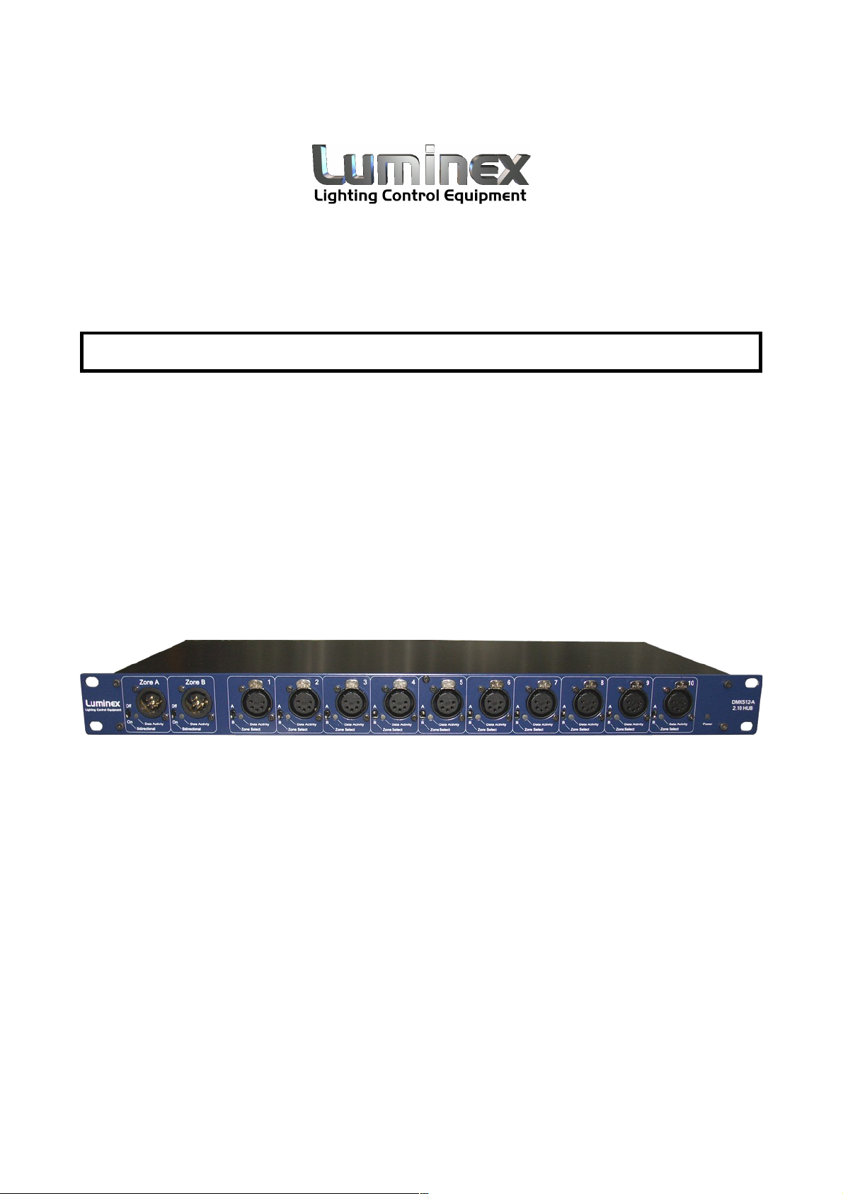
• DMX input
Two Neutrik 5 pin gold plated male connectors are provided as zone A and
zone B input.
Connector Function
Pin 1 Signal common (0 volt)
Pin 2 Data complement (-)
Pin 3 Data true (+)
Pin 4 Not used
Pin 5 Not used
Both inputs are compliant with the DMX512-A specification and are
terminated and biased. The 2 inputs are separately optical and galvanic
isolated from the outputs and from each other.
Page 6 of 12 DMX512-A 2.10 HUB
Page 7
Zone A and Zone B input connectors are also provided at the rear of the
device. These inputs are straight through connections of the inputs on the
front and allow input cabling at the back or inside a rack. All 5 pins are
connected to the front inputs and can serve as a real non isolated
through.
On the front panel, a small switch at each input is provided to disable the
bidirectional functionality of each zone independently. This is can be
switched off when legacy DMX equipment is used, that causes reflections
on the DMX lines.
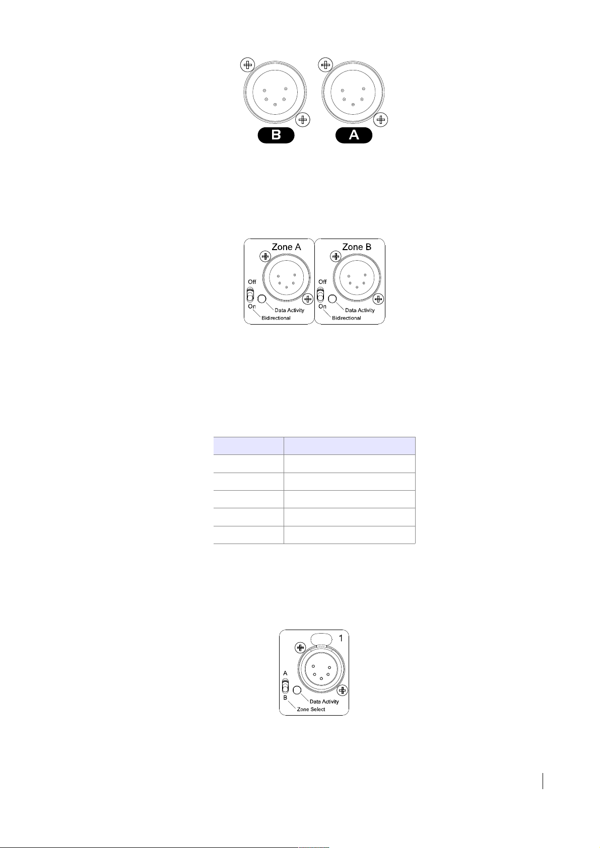
• DMX output
Ten Neutrik 5 pin gold plated female connectors are provided as output.
Connector Function
Pin 1 Signal common (0 volt)
Pin 2 Data complement (-)
Pin 3 Data true (+)
Pin 4 Not used
Pin 5 Not used
All outputs are compliant with the DMX512-A specification and are
terminated. The outputs are separately optical and galvanic isolated from
the inputs and from each other.
A tiny switch is provided with every output to choose between Zone A and
Zone B. In this way you can make any combination of splitter, configuring
DMX512-A 2.10 HUB Page 7 of 12
Page 8

as many outputs you need to transmit DMX from Zone A and the rest from
zone B.
When the bidirectional functionality of the selected zone is active, all
received data on these outputs will be retransmitted on all the outputs of
this zone and on the input connector of this zone.
• Connection type
The DMX512-A 2.10 Hub can be ordered with all 5 pin, 3 pin, EtherCon or
any mix of the above.
The unit can also be custom configured in any Enhanced Function topology
EF (1-4), as described in BSR E1.11, the USITT DMX-512-A standard.
Contact Luminex LCE for more detail.
Following tables show you the connection details.
Pin # DMX512 3-Pin
1 Data common (0 volt)
2 Data complement (-)
3 Data true (+)
Pin # DMX512 5-Pin
1 Data common (0 volt)
2 Data complement (-)
3 Data true (+)
4 Not used (through rear)
5 Not used (through rear)
Pin # EtherCon (DMX 5-
pin)
1 Data 1+ (3)
2 Data 1- (2)
3 Data 2+ (5)
4 Data 2- (4)
5 Not used
6 Not used
7 Data link common 1 (1)
8 Data link common 2 (1)
Page 8 of 12 DMX512-A 2.10 HUB
Page 9

DMX512-A 2.10 HUB Page 9 of 12
Page 10

Features
Isolation
• Individual outlet protection
All ten outputs feature individual isolation and protection. This means that
if a fault occurs on a piece of equipment connected to one output, fixtures
on the other outputs are totally protected. In addition the input
connectors have their own protection, this gives a double barrier between
fixtures and the console and protects the console against a fault on the
mains supply to the buffer itself (i.e. if the buffer unit was inadvertently
connected across two phases).
• 1000 Volts optical isolation barrier
Each outlet has an optical isolator that is capable of withstanding voltages
of up to 1000V. Each isolator has its own power supply eliminating any
direct electrical connection between outputs.
Self-healing technology makes sure that the outlets can resist up to 530V
over its data pairs. This means that after such a fault the outlet works fine
again with normal DMX signals.
• Short circuit protection
Each outlet is protected against short circuits, or incorrectly wired
connectors.
• Modular isolation
All the components that provide the opto-isolation are built into a single
plug-in module for each channel making servicing ultra-simple. In addition
each module is completely interchangeable with other channels including
the input module.
• Line voltage protection
Not only does the Hub protect your various pieces of equipment from
inadvertent DMX-to-mains connection it also protects itself. Each
individual output is protected so that no damage will occur to the buffer
even if they are connected directly to 230V by mistake.
Even a built-in rechargeable battery backups the complete isolation
functionality when a mains failure occurs (see “Power fail management”).
Page 10 of 12 DMX512-A 2.10 HUB
Page 11

Bidirectional and RDM
Bidirectional means that the splitter can work in Half-duplex over data pin
2 and 3.
All outlets are able to receive data. When an outlet receives data, then
this data will be retransmitted on all remaining outlets configured to the
same zone. So all output and input connectors of the same zone will get
all data send on that zone.
This allows bidirectional manufacturer dependent data to be transmitted
between fixtures and controllers. The Hub is protocol independent and
supports in this way communication from different manufacturers such as
High End Systems, Martin Professional, Coemar,...
RDM or Remote Device Management is also supported this way. The
change over time in data direction is conform to the RDM and DMX512-A
specification. The Hub is a non proxy RDM device with no built in RDM
management controlling logic. This allows us to assure a maximum data
delay between incoming data and outgoing data of 1 micro second.
Power fail management
An integrated power management circuit assure optimal power conditions
and fail prove operation.
• Backup battery
A built-in rechargeable backup battery assures the complete operation
(included isolation) of the unit during power failure. When the unit is
connected to mains and switched on, the battery get automatically loaded.
This allows complete functionality for 20 minutes with a full loaded
battery.
The Hub will detect a mains failure and automatically switch over to
internal battery backup.
!!! Make sure to switch off the unit after use. When the unit is not
switched off it will continue to work until that battery is dead. The
next time it will take longer to have the battery completely
recharged. !!!
Note: We recommend to change the battery pack every 3 years. The battery can
easily be replaced. No soldering is needed. The battery pack can be ordered
separately at Luminex LCE.
DMX512-A 2.10 HUB Page 11 of 12
Page 12

• Power status
The status of the mains and battery are shown on a tri-coloured LED on
the front panel next to the power switch.
LED status Power status
Green Working on external mains supply.
Orange No external mains supply.
Working on battery power.
Battery status ok.
Red No external mains supply.
Working on battery power.
Battery status bad.
OUT No external mains supply.
Battery dead (empty).
Or unit is switched off.
Support
• Spare part area
Since serial LUM0060111and upwards, a spare part area is provided on
the board layout. Here the most critical parts are already provided to help
you out in the field.
2 DMX transceivers and 2
optical couplers are provided
t o r ep l a c e t h e I C s o f a
pe rm an ent ly br ok en DM X
outlet.
Page 12 of 12 DMX512-A 2.10 HUB
 Loading...