

Page 1

Ethernet - DMX2 Box
User Guide - V3.0.0
Page 2

LUMINEX Lighting Control Equipment
Ethernet - DMX2 Box User Guide - V3.0.0
Document ethernet_dmx2b_user_guide_v3
Copyright © 2003-2007 LUMINEX Lighting Control Equipment.
All rights reserved.
No part of this documentation may be reproduced or transmitted in any form or by any means, electronic
or mechanical, including photocopying and recording, without the prior written permission of Luminex.
The information in this documentation is supplied without warranty of any kind, either directly or
indirectly, and is subject to change without prior written notice. Luminex, its employees or appointed
representatives will not be held responsible for any damages to software, hardware, or data, howsoever
arising as a direct or indirect result of the product(s) mentioned herein.
Issued by:
Publications Department,
Luminex LCE,
Herent 42,
Neerpelt,
B-3910,
Belgium.
Documentation reviewed January 25, 2007, by Bart Swinnen.
Printed in the EU.
Page 3

Table of Contents
Warranty information....................................................................... 4
Limited warranty.......................................................................... 4
Returning under warranty.............................................................. 4
Freight........................................................................................ 4
General.......................................................................................... 5
Packaging.................................................................................... 5
Description.................................................................................. 5
Specification................................................................................ 5
Dimensions............................................................................... 5
Weight..................................................................................... 5
Electrical.................................................................................. 5
Connectors............................................................................... 5
Environmental........................................................................... 5
Connectivity.................................................................................... 6
Rear Panel................................................................................... 6
Mains....................................................................................... 6
DMX input / output (Optional)..................................................... 6
Ethernet................................................................................... 6
Interface........................................................................................ 7
Front panel.................................................................................. 7
DMX input / output.................................................................... 7
DMX configuration..................................................................... 8
Status indication.................................................................... 8
Unlock the node........................................................................ 9
Reset the node (Out of jail)......................................................... 9
.............................................................................................. 9
Web interface................................................................................ 10
Status....................................................................................... 10
Setup........................................................................................ 11
Node...................................................................................... 11
DMX Routing........................................................................... 12
Merging Policies :..................................................................... 13
Inputs (Local mode).............................................................. 13
Inputs (IP Merging)............................................................... 15
Outputs (IP Merging)............................................................. 16
Recover channel................................................................... 18
Patch files :......................................................................... 18
Network settings.................................................................. 19
IP Settings........................................................................... 19
Global.................................................................................... 20
DMX details......................................................................... 20
Miscellaneous....................................................................... 21
Toolbox..................................................................................... 22
Profile manager....................................................................... 22
Firmware upgrade.................................................................... 23
Additional Documentation................................................................ 24
Page 4

Warranty information
Limited warranty
Unless otherwise stated, your product is covered by a two (2) year parts
and labor limited warranty. It is the owner’s responsibility to furnish
receipts or invoices for verification of purchase, date, and dealer or
distributor. If purchase date cannot be provided, date of manufacture will
be used to determine warranty period.
Returning under warranty
Any Product unit or parts returned to Luminex LCE must be packaged in a
suitable manner to ensure the protection of such Product unit or parts,
and such package shall be clearly and prominently marked to indicate that
the package contains returned Product units or parts. Accompany all
returned Product units or parts with a written explanation of the alleged
problem or malfunction.
Freight
All shipping will be paid by the purchaser. Items under warranty shall have
return shipping paid by the manufacturer only in the European Union.
Under no circumstances will freight collect shipments be accepted. Prepaid
shipping does not include rush expediting such as air freight. Air freight
can be sent customer collect in the European Union.
Warranty is void if the product is misused, damaged, modified in any way,
or for unauthorized repairs or parts.
Page 5

General
Packaging
• 1 x Ethernet – DMX2 Box
• 1 x User guide
Description
The Ethernet - DMX2 Box is an Ethernet node that serves 2 DMX512
outlets, compatible with the ArtNet protocol.
All 2 outlets are conform to RDM and can be used as input or output. The
Ethernet link is a 10BaseT connection on a Neutrik RJ45 Ethercon
connector.
All configuration can be done over Ethernet through a built in website, or
by using the controls on the front end. 3 Hex encoder wheels and switches
are provided to control the universe and direction settings.
this all comes in a half 19'' unit high metal housing.
Specification
Model: Ethernet – DMX2 Box
Manufacturer: LUMINEX Lighting Control Equipment
• Dimensions
209,6 x 172 x 42 (mm)
8,25” x 7,01” x 1,65”
Package: 300 x 220 x 80 (mm)
• Weight
1 kg
• Electrical
Voltages: 90 – 260 VAC
Frequency: 47 – 63 Hz
Rated power: 20 W
Fuse : 125V – 250V, 1A, Slow blow only (5mm x 20mm)
• Connectors
1 x Neutrik RJ45 Ethercon connector
2 x Neutrik gold plated 5 pin XLR (female)
• Environmental
Operating temperature: 0 ~ 60°C (32 ~ 140°F)
Page 6
Connectivity
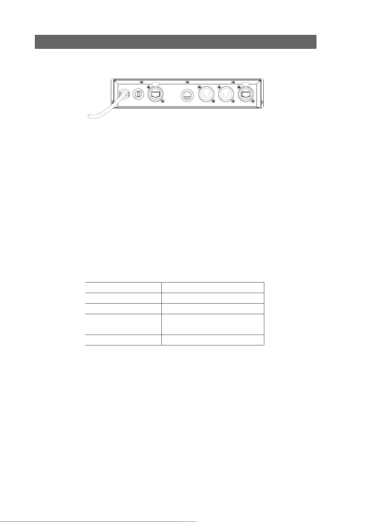
Rear Panel
• Mains
The device operates with an AC voltage between 90V and 260V within a
frequency range of 47Hz and 63Hz.
A fixed power lead with lose cable end is directly connected to the device
(no plug/connector). Please use an authorized plug and connect the cores
in the mains lead in accordance with the following scheme:
Green / Yellow: Earth
Blue: Neutral
Brown: Live
!!! This equipment must be earthed !!!
• DMX input / output (Optional)
2 Neutrik 5 pin gold plated male connectors are provided as DMX through.
Connector Function
Pin 1 Signal common (0 volt)
Pin 2 Data complement (-)
Pin 3 Data true (+)
Pin 4 Not used
Pin 5 Not used
• Ethernet
1Neutrik RJ45 Ethercon is provided as Ethernet link.
An additional Ethercon can be provided as an option together with the
optional DMX male connectors.
Page 7
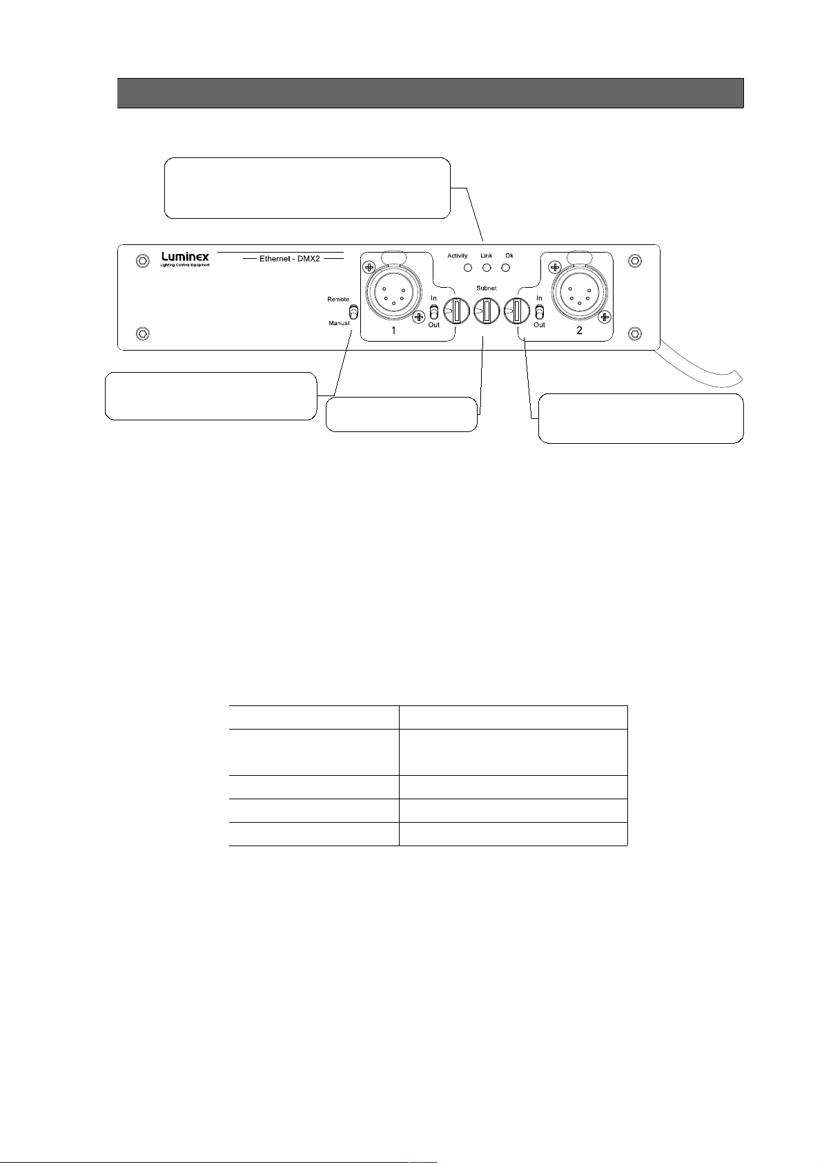
Front panel
LED indication of network activity and link.
Power Ok LED.LED indication of network activity.
Green OK LED status for Node power.
Orange OK LED when node is locked
Remote / manual switch, to choose
between webpage control or manual
control (encoder and switches)
Interface
DMX port direction switch
Input or output
DMX port universe controls
Subnet and subswitch Hex encoder
wheels to set the ArtNet universe.
The front panel interface is provided with 3 Hexadecimal encoder wheels,
3 tiny switches and 3 indication LEDs.
Standard DMX port routing can be done from the front panel (Manual).
Advanced features like merging, backup, etc has to be configured from the
built in web interface (Remote).
• DMX input / output
2 Neutrik 5 pin gold plated female connectors are provided as outlet (input
or output).
Connector Function
Pin 1 Signal common (0 volt)
Pin 2 Data complement (-)
Pin 3 Data true (+)
Pin 4 Not used
Pin 5 Not used
All outlets are compliant with the DMX512-A timing specification and are
terminated and rebiased.
Page 8
• DMX configuration
Every DMX outlet can be configured separately as input or output. These
inputs and outputs get a DMX line address on ArtNet. It is possible to
distribute 256 different DMX lines over ArtNet.
The DMX line address (Universe) on ArtNet is a combination of the node's
Subnet and the outlet's Subswitch. The Subnet divides the possible range
of 256 addresses in groups of 16 addresses. Every node has one Subnet
setting (from 0x0 – 0xF, 0- 15). And every outlet has a separate
Subswitch (from 0x0 – 0xF, 0 – 15). Combined this gives the following
result.
The Subnet is the high nibble of the complete address and the Subswitch
is the low nibble of the address.
Node 1:
Subnet: 0x2 Outlet 1-> Subswitch: 0xC
Result address: 0x2C
In decimal this would be:
Result = (Subnet x 16) + Subswitch
Result address = (2 x 16 ) + 12 = 44
Status indication
3 LEDs are provided to indicate Network Activity, network Link and power
Ok. The OK LED will turn to Orange if the node is locked through the Web
interface or set with a password.
Page 9

• Unlock the node
When the node is set in auto-lock mode or is password protected through
the Web interface, it will automatically lock the front end after 2 min of
inactivity of front end controls. If you try to change something with front
end, the OK LED will blink between green and orange to indicate it is
locked
To unlock the node with no password :
– Remote/Manual switch has to be changed to “Remote”
– Wait 2 seconds
– The OK LED will blink and go to green => the node is unlocked
To unlock the node set with a password :
– Remote/Manual switch has to be changed to “Remote”
– Password has to be set on the encoder wheels
– The OK LED will blink and go to green => the node is unlocked
• Reset the node (Out of jail)
This useful function makes it possible to bring the node in a factory
default.
1. Power down the unit.
2. Put switch on "Remote", both outlets as "input" and all encoder
wheels on "F"
3. Power on the node.
4. Wait until the OK LED will blink in orange
5. Power down the unit
6. Change all encoder wheels back to "0"
7. Power on the unit
8. The node is now in a factory default: IP: 2.0.0.1
Page 10

Web interface
Status
The complete device can be configured from an intuitive web interface.
You just have to browse to the IP address of the unit. If you do not know
the IP address anymore, you can discover it by running Luminet Monitor
(free downloadable tool), which shows all Luminex nodes on the network.
Make sure that the computer, you use to browse, is setup in the correct
network address range (IP 2.x.x.x or 10.x.x.x and subnet 255.0.0.0).
When you're not using a complete network setup (Ethernet switches,
hubs, routers, WLAN, ...), you can also use a cross Ethernet cable and a
PoE injector to directly connect to one unit.
After all connections and setup on the computer are completed, open your
favorite web browser (we recommend Firefox) and enter the IP address
you want to reach in the URL field.
http://2.0.0.1/
Actual DMX routing
Actual Global settings
Navigation Bar
Actual Network settings
You'll end up at the status page of the device. This page has a complete
overview of the device its settings.
The overview shows the actual DMX and network setting / routing of the
complete device.
Page 11

Setup
Choose one of the items in the sub menu to setup the device.
Once in a setup page, help is available on almost every field title. Just click
on the question mark next to the topic. A pop up frame will display the
overall information of each term displayed on the Web interface.
● Node
To setup the node click on the appropriate sub menu item in the Setup
navigation bar (Node).
This is the main settings page. You can setup every single outlet of the
node, as input or output. Select the outlet's direction, mode and universe.
Here you can also change the IP address, Netmask, port and the ArtNet
short and long name indication.
Page 12

● DMX Routing
To better understand the use of all features, let's define each category of
this menu:
Direction : Set the direction you need to the outlet, either Input or
Output. Depending your selection, some features won't be available in the
other categories.
Universe : Select the universe number. The left column number
represents the decimal value, the right column number the Hexadecimal
one. Setting the universe number through Web interface avoids the user
to set Subnet and subswitch settings separately.
Mode : According to the direction you set on the outlet, this menu offers
several mode :
Input : Disabled : Outlet is disabled, better for node performance.
Normal : Outlet set as normal input
Merge : Allow to merge 2 DMX streams.
When outlet 1 is configured as a merged input, the next outlet (2) will be
automatically set as input as well.
Output : Disabled : Outlet is disabled, better for node performance.
Zero : Send all channels with a zero value (for maintenance
only)
Single: Normal output.
IP Merging : This special feature allows you to merge 2 different DMX or
Artnet streams through the network. The merging policy will be mainly
applied on the Output, except for IP backup.
Legend : Set a legend to the outlet, useful to remind yourself what's
connected to that outlet.
Unicast : Artnet is a broadcast protocol, which means that each packet
sent from a single source will be received by all actives equipment on the
network. Unicast provides you to cast you data to a selected IP address,
resulting in a lower use of bandwidth.
All setting that are not applicable for the actual setting will be grayed out
or marked as N/A (Not Applicable).
Page 13

● Merging Policies :
The Ethernet-DMX 2 firmware offers enhanced merging policies that fits
to all kind of setup, even the most complex one !
4 available merging policies can be applied on your DMX network, in 2
main setup categories :
Local merging : 2 different DMX streams are merged on the same
physical device (Node). The merging policy will be mainly set on Inputs.
Illustration 1: Local DMX merging
IP Merging : This special feature allows you to merge 2 different DMX or
Artnet streams through the network. The merging policy will be mainly
applied on the Output, except for IP backup.
Available policies :
– HTP : Highest Take Precedence; Commonly used to merge dimmer
channels
– LTP : Latest Take Precedence; Better suited when using moving lights
– Backup : set one of the 2 outlets as a backup input
– Custom : This is the most complete and efficient policy. This mode
offers you to choose what policy to apply for each channel of each
universe, and also to create a complete custom soft patch. By more,
the merging policy can be remotely controlled triggered by DMX.
The available policies differs if you use either inputs or outputs :
Inputs (Local mode)
Direction Universe Mode
Outlet 1 Input 0(00) Merge
Outlet 2 Input Ch1 HTP, LTP, Backup, Custom
In this example, the selected mode is “Merge”. The second outlet will
automatically be set as a merged input. You will not be able to configure a
universe address for the second outlet, as the merged result will end at
the universe address of the first outlet (primary input). Instead of
universe you will be able to set the starting DMX channel address (1-512).
This indicates from which channel address the second input has to be
merged in. This offset is only available when using HTP or LTP policies.
Page 14

Those rules will be applied on all channel of the universe.
If you choose “Backup”, a small blue icon will appears on the left side of
“Outlet 2” label; then click on it, a pop up frame appears :
Illustration 2: DMX Input backup merging
This menu lets you choose the backup time (from 400 to 9999ms). This
time represents the delay from which the node will automatically switch to
the backup outlet when invalid or no DMX is received anymore on the
primary outlet.
Tick the box if you want the node to auto-recover as soon as valid data is
available again on primary connector.
If you tick off the box, you will have to enable the trigger universe and
select a recover channel (page 20).
If you choose “Custom” policy, a small blue icon will also appear on the
left side of “Outlet 2” label; then click on it, a new pop up frame appears :
Illustration 3: Custom DMX input merging
Page 15

Click on “Show Table” button to see the complete soft patch available for
this outlet.
– Offset S1 & S2 : Enter a value for the desired offset of the starting
channel for outlets 1 or 2; example, for channels 1 to start on the third
channel, enter 3.
– From – To : this range let you quickly set the policy you need on the
channel range of your choice. example, if you need HTP policy on
channels 23 to 145, enter 23 in the “From” field and “145” in the “To”
field. Then select the HTP policy in the “Mode” drop down list, then
press “Set Default Mode”.
– Notice that following policies are available for each channel:
Zero, HTP, LTP, S1 only (Source 1 only), S2 only (Source 2 only); S1
as Backup (Source 1 as backup), S2 as Backup (Source 2 as Backup).
The left column represent the resulting universe channel number
streamed to the network. S1 column represents Source 1 channels and S2
column source 2 channels. It's thus easy to understand that you can
create your own soft patch by entering the channels of your choice in one
of theses column.
Once your patch is created, click submit to close the window, then click
submit again on the node page to record your settings.
Inputs (IP Merging)
Direction Universe Mode IP Merging
Outlet 1 Output 0(01) Normal Disabled
Outlet 2 Input 1(01) Normal Backup
This mode can be very useful in such an application.
Illustration 4: IP Merging
The right side lighting desk is used as a backup desk on stage. This means
that the right side node will automatically switch to that outlet if no ArtNet
packets are available on the selected universe (in that case universe 0).
Select your backup time in the small pop up frame by clicking the left blue
icon, then submit your changes.
Page 16

Outputs (IP Merging)
Direction Universe Mode IP Merging
Outlet 1 Output Single HTP, LTP,
Custom
Outlet 2 Input 1(01) Disable Disabled
This mode can be very useful in the case of 2 control sources located in
different places in the network wants to control the same DMX device in
the same time.
Illustration 5: Output IP merging
In this setup, the right lighting software (S2) is used in the same time as
the left lighting desk (S1). Both streams are merged through the final
output on the right node.
The IP Merging mode provides the following policies when an outlet is set
as output:
– HTP, for all outlet channels
– LTP, for all outlet channels
– Custom, to create a complete soft patch, to set merging policy for
every single channel by IP source and to use the enhanced trigger
system.
Page 17

If you choose “Custom”, click on the blue icon left sided to the “Outlet”
label. A pop up frame appears:
Illustration 6: DMX Output custom IP merging
You can find in this pop up frame similar features as when using the
custom merging on outlets set as inputs (page 14).
The main difference is about the following points :
– IP Source 1 & 2 : Here you can enter the 2 IP addresses assigned to
your 2 control source. In case you don't know one of your source IP
address, simply enter 0.0.0.0 in the address field.
– Universe : Here you can select the universes number streamed by
your control source. This feature is very useful if the 2 sources don't
use the same universe number.
– Trigger channel. This feature allows you to remotely change the
merging policy of one or several dedicated channels through a single
DMX value. From anywhere on the network, you can by example swap
from a “LTP” merge to a “S2 only” policy simply by using a different
DMX trigger channel value. Enter here the DMX channel you want to
use to remotely takeover control of the merging rule. Once you've
selected that channel, you'll need to reach the” Global” web page of the
node to enable and select your Trigger universe. You'll also need to
patch or assign a DMX trigger channel to your control source; here is
the DMX chart of the Luminex DMX trigger channel :
Page 18

0 - 7 Do nothing
8 - 15 Zero out
16 - 23 HTP merge
24 - 31 LTP merge
32 - 39 Source 1 only
40 - 47 Source 2 only
48 - 111 Reserved
112 - 119 Source 1 as backup
120 - 127 Source 2 as backup
128 - 255 Do nothing
Note :Never forget if you control the trigger
channel from more than one source to
press “Do nothing” once you've selected
the desired value. Indeed, if you send
2 different values from 2 different sources
for the trigger channel, the node won't stop
swaping between those values, what results
in a big slowing down of the node processing
power.
Recover channel
If you have set one of a node outlet in IP backup mode, the node will
swap automatically to this outlet in case of DMX failure from the primary
source. Once the primary source is back again available, the node will
automatically swap back to that source if set in Auto-recover mode. We all
know that it can be useful to decide when to swap back to the primary
source (booting time of the desk + loading the right cue in case of desk
failure). Tick off the auto-recover box in the pop up window if you decide
to work in manual recover mode. Then you'll have to enable the trigger
universe in the “Global” Web page and choose a recover channel. You now
have the opportunity to choose to recover either each outlet one by one or
all outlet in one shot.
Here is the Luminex recover channel DMX chart :
0 - 7 Do nothing
8 - 15 Recover outlet 1
16 - 23 Recover outlet 2
24 - 31 Recover outlet 3
32 - 39 Recover outlet 4
40 - 47 Recover outlet 5
48 - 55 Recover outlet 6
56 - 63 Recover outlet 7
64 - 71 Recover outlet 8
72 - 79 Recover all outlets
80 - 255 Do nothing
Patch files :
All those soft patches can be recorded or loaded from or to the node by
using “Load Patch” or “Export patch” buttons. Luminex node recognize .txt
files. These are “TAB” seperated files which can be edited using
spreadsheet software (Excel, OO Calc,...)
Page 19

Network settings
IP Settings
You can enter here the desired ArtNet IP address and Netmask you want
to use. If you're not confident with ArtNet IP setting, tick the “ArtNet
compliant?” box for the node to warn you in case of mistake. ArtNet IP
addresses usually looks like 2.x.x.x or 10.x.x.x.
You're not obliged to work with ArtNet IP addresses. If you wish to work
with usual IT IP addresses as 192.168.x.x, there's no problem for you to
set such address on the node. Please remember that your node will thus
not be visible on the network from devices set with conventional ArtNet IP
addresses (2.x.x.x or 10.x.x.x).
The Port field allows you to change the UDP port used on the network to
transmit your UDP ArtNet packets. Luminex recommend no to change this
value.
Node identification :
Enter here a small and long name to easily identify your node on the
network through a Web interface, ArtNet compliant softwares or Luminex
LumiNet monitor.
Page 20

• Global
Some global settings can be altered by clicking Global in the Setup sub
menu. Device Settings
Here you can change the device's ID number which is indicated on
LumiNet monitor.
You can also enable the Trigger universe to remotely control your merging
policy through any DMX source. The node will listen to the specified
universe entered in the universe field.
You can set your Recover channel if you use the manual recovery mode
(page 14, 18).
DMX details
The DMX frame rate setting for all outlets. This can be set from 20 to 44
frames per second.
DMX Break time can be set from 92 – 180 us
DMX Mark After Break (MAB) time can be set from 12-88 us
DMX Output time can be set to 1 – 10 minutes or continuously. This time
sets how long an output remains outputting it's last DMX levels after no
valid DMX packet came in for that particular universe on ArtNet.
Page 21

Miscellaneous
This part is about security and warnings :
– Verbose level : Select if you want to see error messages on the front
end OK LED.
– Lock Mode: select the security level you want to be applied on your
Node 2 front end. Auto lock will force the Node to lock all wheels
encoders and switches after 2 minutes of front end inactivity.
Password protected mode will guide you to set a password into the
“locking code” field. Once the node is locked, you'll have to enter the 3
digit password through wheel encoders or through Web interface
password field.
For these 2 lock modes, the OK LED will turn Orange to indicate the
node is locked. Read the “Unlock the Node” chapter to see the
complete procedure.
Page 22

Toolbox
Export profile
Download link to save
selected profile
When clicking on Tools in the navigation bar, a sub menu appears. Choose
one of the items in the sub menu.
• Profile manager
The profile manager is able to store 20 profiles. All profiles are stored on
the device.
A preview of the complete configuration stored in a profile is shown when
a profile is selected from the drop down list. When an empty profile is
selected, no preview will be shown.
Once a profile is selected you can choose to recall it, to save actual
settings as a profile, or to delete the profile.
Import profile
To upload a stored profile
from PC or laptop
When recalling a profile, an other page will appear to ask whether to recall
your network settings as well or only the outlet routings.
When saving a profile a next page will ask you to fill in a profile name.
Page 23

• Firmware upgrade
The firmware upgrade page allows you to select a downloaded firmware
file and upload it to the device.
This page shows the actual firmware version running on the unit below the
file upload field.
The latest firmware file can always be downloaded from the Luminex web
pages.
Http://www.luminex.be
To install the firmware on the Ethernet-DMX2 follow these steps:
1. Download the .zip file and save it on your hard disk.
2. Extract the .zip file.
3. Please read the "ChangeNote.txt" for latest release changes.
4. Browse to the device its IP address with your favorite web browser.
5. Click Toolbox -> Firmware upgrade.
6. Browse to the extracted upgrade file on your hard disk
(upgrade_eth_dmx2.tgz).
7. Select the file and press on the "Upgrade" button.
8. The upgrade file will be sent to the device.
9. Wait until the device has rebooted.
10.Enter the IP number of the device in your browser and check at
Toolbox -> Firmware upgrade if the current version is set to the
right version number. If the number is the same as mentioned with
the file than the upgrade has succeeded.
Page 24

Additional Documentation
All additional documentation can be downloaded from our web pages in
the support section.
Http://www.luminex.be
--> Support
 Loading...