

Page 1

An Oshkosh Corporation Company
Service Manual
Model
944E-42
S/N 0160041827 & After
31200355
Original
December 31, 2011
Page 2

Page 3

December 31, 2011 - A - Original Issue
EFFECTIVITY PAGE
31200355 944E-42 i
Page 4

EFFECTIVITY PAGE
944E-42 31200355-ii
Page 5

SECTION CONTENTS
Section Subject Page
Section 1
Safety Practices . . . . . . . . . . . . . . . . . . . . . . . . . . . . . . . . . . . . . . . . . . . . . . . . . . . . . . . 1.1
1.1 Introduction . . . . . . . . . . . . . . . . . . . . . . . . . . . . . . . . . . . . . . . . . . . . . . . . . . . . . . . . . . 1.2
1.2 Disclaimer . . . . . . . . . . . . . . . . . . . . . . . . . . . . . . . . . . . . . . . . . . . . . . . . . . . . . . . . . . . 1.2
1.3 Operation & Safety Manual . . . . . . . . . . . . . . . . . . . . . . . . . . . . . . . . . . . . . . . . . . . . . . 1.2
1.4 Do Not Operate Tags . . . . . . . . . . . . . . . . . . . . . . . . . . . . . . . . . . . . . . . . . . . . . . . . . . . 1.2
1.5 Safety Information . . . . . . . . . . . . . . . . . . . . . . . . . . . . . . . . . . . . . . . . . . . . . . . . . . . . . 1.2
1.6 Safety Instructions . . . . . . . . . . . . . . . . . . . . . . . . . . . . . . . . . . . . . . . . . . . . . . . . . . . . .1.3
1.7 Safety Decals. . . . . . . . . . . . . . . . . . . . . . . . . . . . . . . . . . . . . . . . . . . . . . . . . . . . . . . . .1.4
Section 2
General Information and Specifications . . . . . . . . . . . . . . . . . . . . . . . . . . . . . . . . . . . . 2.1
2.1 Replacement Parts and Warranty Information . . . . . . . . . . . . . . . . . . . . . . . . . . . . . . . . 2.2
2.2 Torque Charts . . . . . . . . . . . . . . . . . . . . . . . . . . . . . . . . . . . . . . . . . . . . . . . . . . . . . . . .2.3
2.3 Specifications. . . . . . . . . . . . . . . . . . . . . . . . . . . . . . . . . . . . . . . . . . . . . . . . . . . . . . . . . 2.11
2.4 Fluid and Lubricant Capacities. . . . . . . . . . . . . . . . . . . . . . . . . . . . . . . . . . . . . . . . . . . . 2.13
2.5 Service and Maintenance Schedules. . . . . . . . . . . . . . . . . . . . . . . . . . . . . . . . . . . . . . . 2.15
2.6 Lubrication Schedules . . . . . . . . . . . . . . . . . . . . . . . . . . . . . . . . . . . . . . . . . . . . . . . . . . 2.18
Section 3
Boom . . . . . . . . . . . . . . . . . . . . . . . . . . . . . . . . . . . . . . . . . . . . . . . . . . . . . . . . . . . 3.1
3.1 Boom System Component Terminology. . . . . . . . . . . . . . . . . . . . . . . . . . . . . . . . . . . . . 3.2
3.2 Boom System. . . . . . . . . . . . . . . . . . . . . . . . . . . . . . . . . . . . . . . . . . . . . . . . . . . . . . . . . 3.3
3.3 Boom Assembly Maintenance . . . . . . . . . . . . . . . . . . . . . . . . . . . . . . . . . . . . . . . . . . . . 3.3
3.4 Boom Extend and Retract Chains . . . . . . . . . . . . . . . . . . . . . . . . . . . . . . . . . . . . . . . . . 3.14
3.5 Boom Wear Pads. . . . . . . . . . . . . . . . . . . . . . . . . . . . . . . . . . . . . . . . . . . . . . . . . . . . . . 3.22
3.6 Quick Attach Assembly . . . . . . . . . . . . . . . . . . . . . . . . . . . . . . . . . . . . . . . . . . . . . . . . . 3.23
3.7 Forks . . . . . . . . . . . . . . . . . . . . . . . . . . . . . . . . . . . . . . . . . . . . . . . . . . . . . . . . . . . . . . . 3.23
3.8 Troubleshooting . . . . . . . . . . . . . . . . . . . . . . . . . . . . . . . . . . . . . . . . . . . . . . . . . . . . . . .3.24
3.9 Emergency Boom Lowering. . . . . . . . . . . . . . . . . . . . . . . . . . . . . . . . . . . . . . . . . . . . . . 3.27
Section 4
Cab and Covers . . . . . . . . . . . . . . . . . . . . . . . . . . . . . . . . . . . . . . . . . . . . . . . . . . . . . . . . 4.1
4.1 Operator’s Cab and Covers Component Terminology . . . . . . . . . . . . . . . . . . . . . . . . . . 4.2
4.2 Operator’s Cab. . . . . . . . . . . . . . . . . . . . . . . . . . . . . . . . . . . . . . . . . . . . . . . . . . . . . . . .4.3
4.3 Cab Components. . . . . . . . . . . . . . . . . . . . . . . . . . . . . . . . . . . . . . . . . . . . . . . . . . . . . . 4.3
4.4 Enclosed Cab (Optional) Components . . . . . . . . . . . . . . . . . . . . . . . . . . . . . . . . . . . . . 4.8
4.5 Cab Removal . . . . . . . . . . . . . . . . . . . . . . . . . . . . . . . . . . . . . . . . . . . . . . . . . . . . . . . . . 4.9
4.6 Cab Installation . . . . . . . . . . . . . . . . . . . . . . . . . . . . . . . . . . . . . . . . . . . . . . . . . . . . . . . 4.11
4.7 Valve Plate . . . . . . . . . . . . . . . . . . . . . . . . . . . . . . . . . . . . . . . . . . . . . . . . . . . . . . . . . . . 4.12
944E-42
i
Page 6

Section Subject Page
Section 5
Axles, Drive Shafts, Wheels and Tires . . . . . . . . . . . . . . . . . . . . . . . . . . . . . . . . . . . . . . 5.1
5.1 Axle, Drive Shaft and Wheel Component Terminology . . . . . . . . . . . . . . . . . . . . . . . . . 5.2
5.2 General Information . . . . . . . . . . . . . . . . . . . . . . . . . . . . . . . . . . . . . . . . . . . . . . . . . . . . 5.3
5.3 Axle Assemblies. . . . . . . . . . . . . . . . . . . . . . . . . . . . . . . . . . . . . . . . . . . . . . . . . . . . . . . 5.3
5.4 Drive Shafts . . . . . . . . . . . . . . . . . . . . . . . . . . . . . . . . . . . . . . . . . . . . . . . . . . . . . . . . . . 5.10
5.5 Wheels and Tires . . . . . . . . . . . . . . . . . . . . . . . . . . . . . . . . . . . . . . . . . . . . . . . . . . . . . . 5.11
5.6 Brakes . . . . . . . . . . . . . . . . . . . . . . . . . . . . . . . . . . . . . . . . . . . . . . . . . . . . . . . . . . . . . . 5.12
5.7 Towing a Disabled Machine . . . . . . . . . . . . . . . . . . . . . . . . . . . . . . . . . . . . . . . . . . . . . . 5.13
Section 6
Transmission . . . . . . . . . . . . . . . . . . . . . . . . . . . . . . . . . . . . . . . . . . . . . . . . . . . . . . . . . .6.1
6.1 Transmission Assembly Component Terminology . . . . . . . . . . . . . . . . . . . . . . . . . . . . . 6.2
6.2 Transmission Serial Number . . . . . . . . . . . . . . . . . . . . . . . . . . . . . . . . . . . . . . . . . . . . . 6.3
6.3 Transmission Specifications And Maintenance Information . . . . . . . . . . . . . . . . . . . . . . 6.3
6.4 Transmission Replacement . . . . . . . . . . . . . . . . . . . . . . . . . . . . . . . . . . . . . . . . . . . . . . 6.3
6.5 Troubleshooting . . . . . . . . . . . . . . . . . . . . . . . . . . . . . . . . . . . . . . . . . . . . . . . . . . . . . . .6.7
6.6 Transfer Case Component Terminology. . . . . . . . . . . . . . . . . . . . . . . . . . . . . . . . . . . . . 6.11
6.7 Transfer Case. . . . . . . . . . . . . . . . . . . . . . . . . . . . . . . . . . . . . . . . . . . . . . . . . . . . . . . . . 6.12
6.8 Transfer Case Serial Number. . . . . . . . . . . . . . . . . . . . . . . . . . . . . . . . . . . . . . . . . . . . . 6.12
6.9 Transfer Case Maintenance . . . . . . . . . . . . . . . . . . . . . . . . . . . . . . . . . . . . . . . . . . . . . . 6.12
6.10 Transfer Case Replacement. . . . . . . . . . . . . . . . . . . . . . . . . . . . . . . . . . . . . . . . . . . . . . 6.12
6.11 Troubleshooting . . . . . . . . . . . . . . . . . . . . . . . . . . . . . . . . . . . . . . . . . . . . . . . . . . . . . . . 6.14
Section 7
Engine . . . . . . . . . . . . . . . . . . . . . . . . . . . . . . . . . . . . . . . . . . . . . . . . . . . . . . . . . . . 7.1
7.1 Introduction - Cummins QSB 4.5. . . . . . . . . . . . . . . . . . . . . . . . . . . . . . . . . . . . . . . . . . 7.2
7.2 Engine Serial Number . . . . . . . . . . . . . . . . . . . . . . . . . . . . . . . . . . . . . . . . . . . . . . . . . . 7.4
7.3 Specifications and Maintenance Information . . . . . . . . . . . . . . . . . . . . . . . . . . . . . . . . . 7.4
7.4 Engine Cooling System . . . . . . . . . . . . . . . . . . . . . . . . . . . . . . . . . . . . . . . . . . . . . . . . . 7.4
7.5 Engine Electrical System . . . . . . . . . . . . . . . . . . . . . . . . . . . . . . . . . . . . . . . . . . . . . . . . 7.5
7.6 Fuel System. . . . . . . . . . . . . . . . . . . . . . . . . . . . . . . . . . . . . . . . . . . . . . . . . . . . . . . . . .7.5
7.7 Engine Exhaust System. . . . . . . . . . . . . . . . . . . . . . . . . . . . . . . . . . . . . . . . . . . . . . . . . 7.7
7.8 Air Cleaner Assembly. . . . . . . . . . . . . . . . . . . . . . . . . . . . . . . . . . . . . . . . . . . . . . . . . . . 7.8
7.9 Engine Replacement . . . . . . . . . . . . . . . . . . . . . . . . . . . . . . . . . . . . . . . . . . . . . . . . . . . 7.9
7.10 Troubleshooting . . . . . . . . . . . . . . . . . . . . . . . . . . . . . . . . . . . . . . . . . . . . . . . . . . . . . . . 7.13
Section 8
Hydraulic System . . . . . . . . . . . . . . . . . . . . . . . . . . . . . . . . . . . . . . . . . . . . . . . . . . . . . . . 8.1
8.1 Hydraulic Component Terminology . . . . . . . . . . . . . . . . . . . . . . . . . . . . . . . . . . . . . . . . 8.2
8.2 Safety Information . . . . . . . . . . . . . . . . . . . . . . . . . . . . . . . . . . . . . . . . . . . . . . . . . . . . . 8.3
8.3 Hydraulic Pressure Diagnosis . . . . . . . . . . . . . . . . . . . . . . . . . . . . . . . . . . . . . . . . . . . . 8.4
8.4 Hydraulic Circuits . . . . . . . . . . . . . . . . . . . . . . . . . . . . . . . . . . . . . . . . . . . . . . . . . . . . . .8.5
8.5 Hydraulic Reservoir . . . . . . . . . . . . . . . . . . . . . . . . . . . . . . . . . . . . . . . . . . . . . . . . . . . . 8.13
8.6 Hydraulic System Pump. . . . . . . . . . . . . . . . . . . . . . . . . . . . . . . . . . . . . . . . . . . . . . . . . 8.16
8.7 Valves and Manifolds . . . . . . . . . . . . . . . . . . . . . . . . . . . . . . . . . . . . . . . . . . . . . . . . . . . 8.17
8.8 Hydraulic Cylinders . . . . . . . . . . . . . . . . . . . . . . . . . . . . . . . . . . . . . . . . . . . . . . . . . . . . 8.38
ii
944E-42
Page 7

Section Subject Page
Section 9
Electrical System . . . . . . . . . . . . . . . . . . . . . . . . . . . . . . . . . . . . . . . . . . . . . . . . . . . . . . 9.1
9.1 Electrical Component Terminology . . . . . . . . . . . . . . . . . . . . . . . . . . . . . . . . . . . . . . . . 9.3
9.2 Specifications. . . . . . . . . . . . . . . . . . . . . . . . . . . . . . . . . . . . . . . . . . . . . . . . . . . . . . . . . 9.4
9.3 Safety Information . . . . . . . . . . . . . . . . . . . . . . . . . . . . . . . . . . . . . . . . . . . . . . . . . . . . . 9.4
9.4 Fuses and Relays . . . . . . . . . . . . . . . . . . . . . . . . . . . . . . . . . . . . . . . . . . . . . . . . . . . . . 9.4
9.5 Electrical Schematics. . . . . . . . . . . . . . . . . . . . . . . . . . . . . . . . . . . . . . . . . . . . . . . . . . . 9.6
9.6 Circuit Breakdowns . . . . . . . . . . . . . . . . . . . . . . . . . . . . . . . . . . . . . . . . . . . . . . . . . . . . 9.12
9.7 Engine Start Circuit . . . . . . . . . . . . . . . . . . . . . . . . . . . . . . . . . . . . . . . . . . . . . . . . . . . . 9.14
9.8 Charging Circuit . . . . . . . . . . . . . . . . . . . . . . . . . . . . . . . . . . . . . . . . . . . . . . . . . . . . . . .9.15
9.9 Window Wiper/Washer Windshield Wiper Motor . . . . . . . . . . . . . . . . . . . . . . . . . . . . . . 9.16
9.10 Cab Heater and Fan. . . . . . . . . . . . . . . . . . . . . . . . . . . . . . . . . . . . . . . . . . . . . . . . . . . . 9.20
9.11 Switches and Solenoids. . . . . . . . . . . . . . . . . . . . . . . . . . . . . . . . . . . . . . . . . . . . . . . . . 9.21
9.12 Dash Switches . . . . . . . . . . . . . . . . . . . . . . . . . . . . . . . . . . . . . . . . . . . . . . . . . . . . . . . .9.36
9.13 Troubleshooting . . . . . . . . . . . . . . . . . . . . . . . . . . . . . . . . . . . . . . . . . . . . . . . . . . . . . . . 9.37
Section 10
Stabil-TRAK™System . . . . . . . . . . . . . . . . . . . . . . . . . . . . . . . . . . . . . . . . . . . . . . . . . . 10.1
10.1 Stabil-TRAK™ System Component Terminology. . . . . . . . . . . . . . . . . . . . . . . . . . . . . 10.2
10.2 Stabil-TRAK™ Description. . . . . . . . . . . . . . . . . . . . . . . . . . . . . . . . . . . . . . . . . . . . . . 10.3
10.3 Stabil-TRAK™ Electrical Circuit Operation and Troubleshooting. . . . . . . . . . . . . . . . . 10.4
10.4 Stabil-TRAK™ System Test. . . . . . . . . . . . . . . . . . . . . . . . . . . . . . . . . . . . . . . . . . . . . 10.10
10.5 Stabil-TRAK™ Hydraulic Circuit Operation and Troubleshooting . . . . . . . . . . . . . . . . 10.13
Section 11
Transfer Carriage . . . . . . . . . . . . . . . . . . . . . . . . . . . . . . . . . . . . . . . . . . . . . . . . . . . . . . 11.1
11.1 Transfer Carriage Component Terminology . . . . . . . . . . . . . . . . . . . . . . . . . . . . . . . . . . 11.2
11.2 Transfer Carriage . . . . . . . . . . . . . . . . . . . . . . . . . . . . . . . . . . . . . . . . . . . . . . . . . . . . . .11.3
11.3 Transfer Carriage Maintenance . . . . . . . . . . . . . . . . . . . . . . . . . . . . . . . . . . . . . . . . . . . 11.3
11.4 Troubleshooting . . . . . . . . . . . . . . . . . . . . . . . . . . . . . . . . . . . . . . . . . . . . . . . . . . . . . . . 11.22
944E-42
iii
Page 8

Section Subject Page
iv
944E-42
Page 9

Section 1
Safety Practices
Contents
PARAGRAPH TITLE PAGE
1.1 Introduction . . . . . . . . . . . . . . . . . . . . . . . . . . . . . . . . . . . . . . . . . . . . . . . . . . . . . . . 1-2
1.2 Disclaimer . . . . . . . . . . . . . . . . . . . . . . . . . . . . . . . . . . . . . . . . . . . . . . . . . . . . . . . . 1-2
1.3 Operation & Safety Manual. . . . . . . . . . . . . . . . . . . . . . . . . . . . . . . . . . . . . . . . . . . 1-2
1.4 Do Not Operate Tags. . . . . . . . . . . . . . . . . . . . . . . . . . . . . . . . . . . . . . . . . . . . . . . . 1-2
1.5 Safety Information. . . . . . . . . . . . . . . . . . . . . . . . . . . . . . . . . . . . . . . . . . . . . . . . . . 1-2
1.5.1 Safety Alert System and Signal Words. . . . . . . . . . . . . . . . . . . . . . . . . . . 1-2
1.6 Safety Instructions . . . . . . . . . . . . . . . . . . . . . . . . . . . . . . . . . . . . . . . . . . . . . . . . . 1-3
1.6.1 Personal Hazards . . . . . . . . . . . . . . . . . . . . . . . . . . . . . . . . . . . . . . . . . . . 1-3
1.6.2 Equipment Hazards. . . . . . . . . . . . . . . . . . . . . . . . . . . . . . . . . . . . . . . . . . 1-3
1.6.3 General Hazards. . . . . . . . . . . . . . . . . . . . . . . . . . . . . . . . . . . . . . . . . . . . 1-3
1.6.4 Operational Hazards . . . . . . . . . . . . . . . . . . . . . . . . . . . . . . . . . . . . . . . . . 1-4
1.7 Safety Decals. . . . . . . . . . . . . . . . . . . . . . . . . . . . . . . . . . . . . . . . . . . . . . . . . . . . . . 1-4
944E-42
1-1
Page 10
Safety Practices
1.1 INTRODUCTION
This service manual provides general directions for
accomplishing service and repair procedures. Following
the procedures in this manual will help assure safety and
equipment reliability.
Read, understand and follow the information in this
manual, and obey all locally approved safety practices,
procedures, rules, co des, regulatio ns and laws.
These instructions cannot cover all details or variations in
the equipment, procedures, or processes described, nor
provide directions for meeting every possible continge ncy
during operation, maintenance, or testing. When additional
information is desired consu l t th e l o c a l distr ibutor.
Many factors contribute to unsafe conditions: carelessness,
fatigue, overload, inattentiveness, unfamiliarity, even
drugs and alcohol, among others. For op tim al safe ty,
encourage everyone to think, and to act, safely.
Appropriate service methods and proper repair
procedures are essential for the safety of the individual
doing the work, for the safety of the operator, and for the
safe, reliable operation of the machine. All references to
the right side, left side, front and rear are given from the
operator’s seat looking in a forward direction.
Supplementary information is available from JLG in the
form of Service Bulletins, Service Campaigns, Service
Training Schools, the JLG website, other literature, and
through updates to the manual itself.
1.2 DISCLAIMER
1.4 DO NOT OPERATE TAGS
Place Do Not Operate Tags on the ignition key switch and
the steering wheel before attempting to perform any
service or maintenance. Remove key and disconnect
battery leads.
1.5 SAFETY INFORMATION
To avoid possible death or injury, carefully read,
understand and comply with all safety messages.
In the event of an accident, know where to obtain medical
assistance and how to use a first-aid kit and fire
extinguisher/fire suppression system. Keep emergency
telephone numbers (fire department, ambula nce, rescue
squad/paramedics, police department, etc.) nearby. If
working alone, check with another person routinely to
help assure personal safety.
1.5.1 Safety Alert System and Signal Words
DANGER
DANGER indicates an imminently hazardous situation
which, if not avoided, will result in death or serious injury.
WARNING
All information in this manual is based on the latest
product information available at the time of publication.
JLG reserves the right to make changes and
improvements to its products, and to discontinue the
manufacture of any product, at its discretion at any time
without public notice or obligation.
1.3 OPERATION & SAFETY MANUAL
The mechanic must not operate the machine until the
Operation & Safety Manual has been read & understood,
training has been accomplished and operation of the
machine has been completed under the su pervision of an
experienced and qualified operator.
An Operation & Safety Manual is supplied with each
machine and must be kept in the manual holder located
in the cab. In the event that the Operation & Safety
Manual is missing, consult the local dist ributor before
proceeding.
1-2
WARNING indicates a potentially hazardous situation
which, if not avoided, could result in death or serious
injury.
CAUTION
CAUTION indicates a potentially hazardous situation
which, if not avoided, may result in minor or moderate
injury.
944E-42
Page 11

Safety Practices
1.6 SAFETY INSTRUCTIONS
Following are general safety statements to consider before
performing maintenance procedures on the telehandler.
Additional statements related to specific tasks and
procedures are located throughout this manual and are
listed prior to any work instructions to provide safety
information before the potential of a hazard occur s.
For all safety messages, carefully read, understand and
follow the instructions before
1.6.1 Personal Hazards
PERSONAL SAFETY GEAR: Wear all the protective
clothing and personal safety gear necessary to perform
the job safely. This might include heavy gloves, safety
glasses or goggles, filter mask or respirator, safety shoes
or a hard hat.
LIFTING: NEVER lift a heavy object without the help of at
least one assistant or a suitable sling and hoist.
1.6.2 Equipment Hazards
LIFTING OF EQUIPMENT: Before using any lifting
equipment (chains, slings, brackets, hooks, etc.), verify
that it is of the proper capacity, in good working order, and
is properly attached.
NEVER stand or otherwise become positioned under a
suspended load or under raised equipment. The load or
equipment could fall or tip.
DO NOT use a hoist, jack or jack stands only to support
equipment. Always support equipment with the proper
capacity blocks or stands properly rated for the load.
HAND TOOLS: Always use the proper tool for the job;
keep tools clean and in good working order, and use
special service tools only as recommended.
proceeding.
1.6.3 General Hazards
SOLVENTS: Only use approved solvents that are known
to be safe for use.
HOUSEKEEPING: Keep the work area and operator’s
cab clean, and remove all hazards (debris, o il, tools, etc.).
FIRST AID: Immediately clean, dress and report all injuries
(cuts, abrasions, burns, etc.), no matter how minor the
injury may seem. Know the location of a First Aid Kit, and
know how to use it.
CLEANLINESS: Wear eye protection, and clean all
components with a high-pressure or steam cleaner
before attempting service.
When removing hydraulic components, plug hose ends
and connections to prevent excess leakage and
contamination. Place a suitable catch basin beneath the
machine to capture fluid run-off.
It is good practice to avoid pressure-washing electrical/
electronic components. In the event pressure-washing
the machine is needed, ensure the mach ine is shut down
before pressure-washing. Should pressure-washing be
utilized to wash areas containing electrical/electronic
components, JLG recommends a maximum pressure of
750 psi (52 bar) at a minimum distance of 12 in. (30,5 cm)
away from these components. If electrical/electronic
components are sprayed, spraying must not be direct and
for brief time periods to avoid heavy saturation,
Check and obey all Federal, State and/or Local
regulations regarding waste storage, disposal and
recycling.
944E-42
1-3
Page 12

Safety Practices
1.6.4 Operational Hazards
ENGINE: Stop the engine before performing any service
unless specifically instructed otherwise.
VENTILATION: Avoid prolonged engine operation in
enclosed areas without adequate ventilation.
SOFT SURFACES AND SLOPES: NEVER work on a
machine that is parked on a soft surface or slope. The
machine must be on a hard level surface, with the wheels
blocked before performing any service.
FLUID TEMPERATURE: NEVER work on a machine
when the engine, cooling or hydraulic systems are hot.
Hot components and fluids can cause severe burns.
Allow systems to cool before proceeding.
FLUID PRESSURE: Before loosening any hydraulic or
diesel fuel component, hose or tube, turn the engine
OFF. Wear heavy, protective gloves and eye protection.
NEVER check for leaks using any part of your body; use
a piece of cardboard or wood instead. If injured, seek
medical attention immediately. Diesel fluid leaking und er
pressure can explode. Hydraulic fluid and diesel fuel
leaking under pressure can penetrate the skin, cause
infection, gangrene and other serious person al injury.
Relieve all pressure before disconnecting any
component, part, line or hose. Slowly loosen parts and
allow release of residual pressure before removing any
part or component. Before starting the en gine or applying
pressure, use components, parts, hoses and pipes that
are in good condition, connected properly and are
tightened to the proper torque . Capture fluid in an
appropriate container and dispose of in accor da nce with
prevailing environmental regulations.
RADIATOR CAP: The cooling system is under pressure,
and escaping coolant can cause severe burns and eye
injury. To prevent personal injury, NEVER remove the
radiator cap while the cooling system is hot. Wear safety
glasses. Turn the radiator cap to the first stop and allo w
pressure to escape before removing the cap completely.
Failure to follow the safety practices could result in death
or serious injury.
FLUID FLAMABILTITY: DO NOT service the fuel or
hydraulic systems near an open flame, spar ks or smoking
materials.
NEVER drain or store fluids in an open container. Engine
fuel and hydraulic fluid are flammable and can cause a
fire and/or explosion.
DO NOT mix gasoline or alcohol with diesel fuel. The
mixture can cause an explosion.
PRESSURE TESTING: When conducting any test, only
use test equipment that is correctly calibrated and in goo d
condition. Use the correct equipment in the proper
manner, and make changes or repairs as indicate d by the
test procedure to achieve the desired result.
LEAVING MACHINE: Lower the forks or attachment to
the ground before leaving the machine.
TIRES: Always keep tires inflated to the proper pr essure
to help prevent tipover. DO NOT over-inflate tires.
NEVER use mismatched tire types, sizes or ply ratings.
Always use matched sets according to machine
specifications.
MAJOR COMPONENTS: Never alter, remove, or
substitute any items such as counterweights, tires,
batteries or other items that may reduce or affect the
overall weight or stability of the machine.
BATTERY: DO NOT charge a frozen battery.Charging a
frozen battery may cause it to explode. Allow the battery
to thaw before jump-starting or connectin g a ba tte r y
charger.
1.7 SAFETY DECALS
Check that all safety decals are present and readable on
the machine. Refer to the Operation & Safet y Manual
supplied with machine for information.
1-4
944E-42
Page 13

Section 2
General Information and Specifications
Contents
PARAGRAPH TITLE PAGE
2.1 Replacement Parts and Warranty Information . . . . . . . . . . . . . . . . . . . . . . . . . . . 2-2
2.2 T orque Charts . . . . . . . . . . . . . . . . . . . . . . . . . . . . . . . . . . . . . . . . . . . . . . . . . . . . . 2-3
2.2.1 SAE Fastener Torque Chart . . . . . . . . . . . . . . . . . . . . . . . . . . . . . . . . . . . 2-3
2.2.2 Metric Fastener Torque Chart . . . . . . . . . . . . . . . . . . . . . . . . . . . . . . . . . . 2-7
2.2.3 Hydraulic Hose Torque Chart . . . . . . . . . . . . . . . . . . . . . . . . . . . . . . . . . . 2-10
2.3 Specifications . . . . . . . . . . . . . . . . . . . . . . . . . . . . . . . . . . . . . . . . . . . . . . . . . . . . . 2-11
2.3.1 Travel Speeds . . . . . . . . . . . . . . . . . . . . . . . . . . . . . . . . . . . . . . . . . . . . . . 2-11
2.3.2 Hydraulic Cylinder Performance . . . . . . . . . . . . . . . . . . . . . . . . . . . . . . . . 2-11
2.3.3 Electrical System . . . . . . . . . . . . . . . . . . . . . . . . . . . . . . . . . . . . . . . . . . . 2-11
2.3.4 Engine Performance Specifications . . . . . . . . . . . . . . . . . . . . . . . . . . . . . 2-12
2.3.5 Tires . . . . . . . . . . . . . . . . . . . . . . . . . . . . . . . . . . . . . . . . . . . . . . . . . . . . . 2-12
2.4 Fluid and Lubricant Capacities . . . . . . . . . . . . . . . . . . . . . . . . . . . . . . . . . . . . . . . 2-13
2.5 Service and Maintenance Schedules . . . . . . . . . . . . . . . . . . . . . . . . . . . . . . . . . . 2-15
2.5.1 10 & 50 Hour. . . . . . . . . . . . . . . . . . . . . . . . . . . . . . . . . . . . . . . . . . . . . . . 2-15
2.5.2 1st 100, 250 & 1st 500 Hour . . . . . . . . . . . . . . . . . . . . . . . . . . . . . . . . . . . 2-16
2.5.3 500, 1000 & 2000 Hour. . . . . . . . . . . . . . . . . . . . . . . . . . . . . . . . . . . . . . . 2-17
2.6 Lubrication Schedules . . . . . . . . . . . . . . . . . . . . . . . . . . . . . . . . . . . . . . . . . . . . . . 2-18
944E-42
2-1
Page 14
General Information and Specifications
OU0221
1
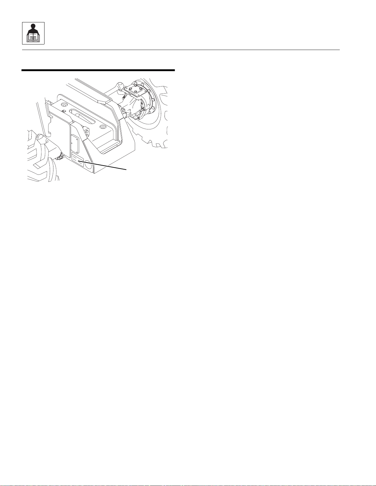
2.1 REPLACEMENT PARTS AND WARRANTY INFORMATION
Before ordering parts or initiating service inquiries, make
note of the machine serial number. The machine serial
number plate (1) is located as ind i ca ted in the fi gu re .
Note: The replacement of any part on this machine with
any other than JLG authorized replacement parts can
adversely affect the performance, durability, or safety of
the machine, and will void the warranty. JLG disclaims
liability for any claims or damages, whether regarding
property damage, personal injury or death arising out of
the use of unauthorized replacement parts.
A warranty registration form must be filled out by the JLG
distributor, signed by the purchaser and returned to JLG
when the machine is sold and/or put into use.
Registration activates the warranty period and helps to
assure that warranty claims are promptly proc essed. To
guarantee full warranty service, verify that the distrib utor
has returned the business reply card of the warranty
registration form to JLG.
2-2
944E-42
Page 15
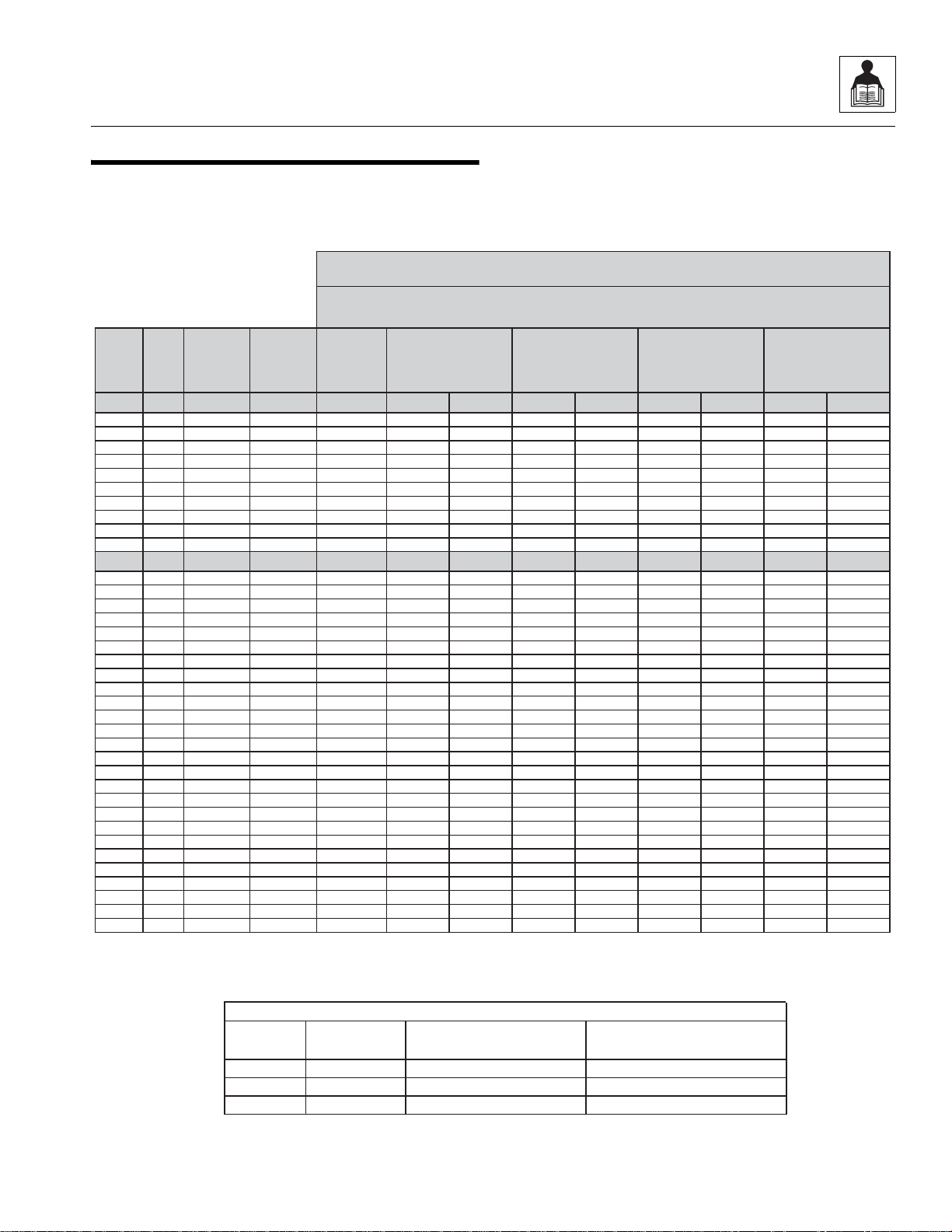
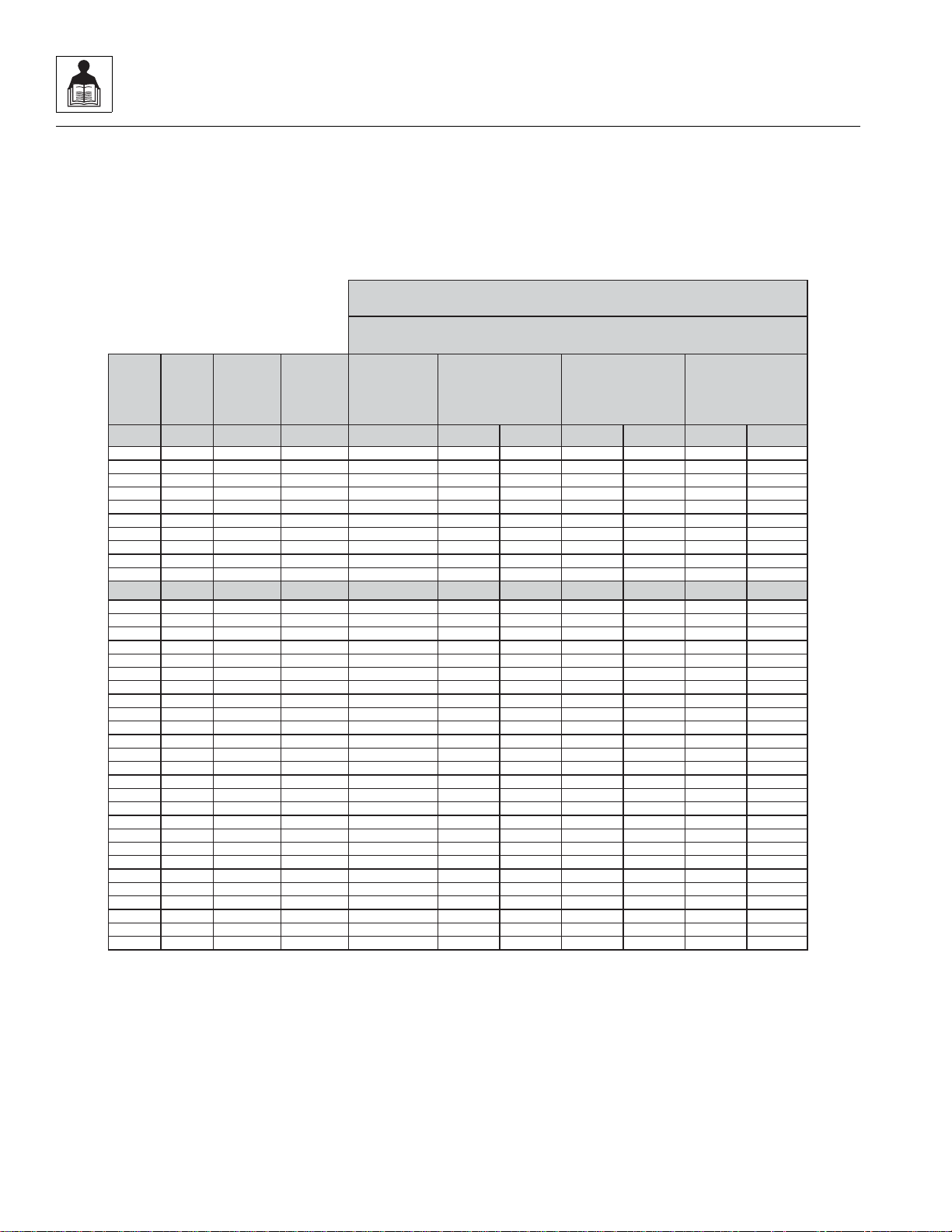
2.2 TORQUE CHARTS
REFERENCE JLG ANEROBIC THREAD LOCKING COMPOUND
Description
0100011
242
TM
Vibra-TITETM121
Medium Strength (Blue)
0100019
271
TM
Vibra-TITETM140
High Strength (Red)
0100071
262
TM
Vibra-TITETM131
Medium - High Strength (Red)
Size TPI Bolt Dia
Tensile
Stress Area
Clamp Load
In Sq In LB IN-LB [N.m] IN-LB [N.m] IN-LB [N.m] IN-LB [N.m]
4 40 0.1120 0.00604 380 8 0.9 6 0.7
48 0.1120 0.00661 420 9 1.0 7 0.8
6 32 0.1380 0.00909 580 16 1.8 12 1.4
40 0.1380 0.01015 610 18 2.0 13 1.5
8 32 0.1640 0.01400 900 30 3.4 22 2.5
36 0.1640 0.01474 940 31 3.5 23 2.6
10 24 0.1900 0.01750 1120 43 4.8 32 3.5
32 0.1900 0.02000 1285 49 5.5 36 4
1/4 20 0.2500 0.0318 2020 96 10.8 75 9 105 12
28 0.2500 0.0364 2320 120 13.5 86 10 135 15
In Sq In LB FT-LB [N.m] FT-LB [N.m] FT-LB [N.m] FT-LB [N.m]
5/16 18 0.3125 0.0524 3340 17 23 13 18 19 26 16 22
24 0.3125 0.0580 3700 19 26 14 19 21 29 17 23
3/8 16 0.3750 0.0775 4940 30 41 23 31 35 48 28 38
24 0.3750 0.0878 5600 35 47 25 34 40 54 32 43
7/16 14 0.4375 0.1063 6800 50 68 35 47 55 75 45 61
20 0.4375 0.1187 7550 55 75 40 54 60 82 50 68
1/2 13 0.5000 0.1419 9050 75 102 55 75 85 116 68 92
20 0.5000 0.1599 10700 90 122 65 88 100 136 80 108
9/16 12 0.5625 0.1820 11600 110 149 80 108 120 163 98 133
18 0.5625 0.2030 12950 120 163 90 122 135 184 109 148
5/8 11 0.6250 0.2260 14400 150 203 110 149 165 224 135 183
18 0.6250 0.2560 16300 170 230 130 176 190 258 153 207
3/4 10 0.7500 0.3340 21300 260 353 200 271 285 388 240 325
16 0.7500 0.3730 23800 300 407 220 298 330 449 268 363
7/8 9 0.8750 0.4620 29400 430 583 320 434 475 646 386 523
14 0.8750 0.5090 32400 470 637 350 475 520 707 425 576
1 8 1.0000 0.6060 38600 640 868 480 651 675 918 579 785
12 1.0000 0.6630 42200 700 949 530 719 735 1000 633 858
1 1/8 7 1.1250 0.7630 42300 800 1085 600 813 840 1142 714 968
12 1.1250 0.8560 47500 880 1193 660 895 925 1258 802 1087
1 1/4 7 1.2500 0.9690 53800 1120 1518 840 1139 1175 1598 1009 1368
12 1.2500 1.0730 59600 1240 1681 920 1247 1300 1768 1118 1516
1 3/8 6 1.3750 1.1550 64100 1460 1979 1100 1491 1525 2074 1322 1792
12 1.3750 1.3150 73000 1680 2278 1260 1708 1750 2380 1506 2042
1 1/2 6 1.5000 1.4050 78000 1940 2630 1460 1979 2025 2754 1755 2379
12 1.5000 1.5800 87700 2200 2983 1640 2224 2300 3128 1974 2676
Values for ZincYellow Chromate Fasteners
SAE GRADE 5 BOLTS & GRADE 2 NUTS
Torque
(Dry)
Torque
Lubricated
3. *ASSEMBLY USES HARDENED WASHER
NOTES: 1. THESETORQUE VALUESDO NOTAPPLYTO CADMIUM PLATED FASTENERS
2. ALL TORQUE VALUES ARE STATIC TORQUE MEASURED PER STANDARD AUDIT METHODS TOLERANCE = ±10%
MY4650J
JLG P/N Loctite® P/N
ND Industries P/N
Torque
Loctite® 262™
OR
Vibra-TITE™ 131
Torque
Loctite® 242™ or 271™
OR
Vibra-TITE™ 111 or 140
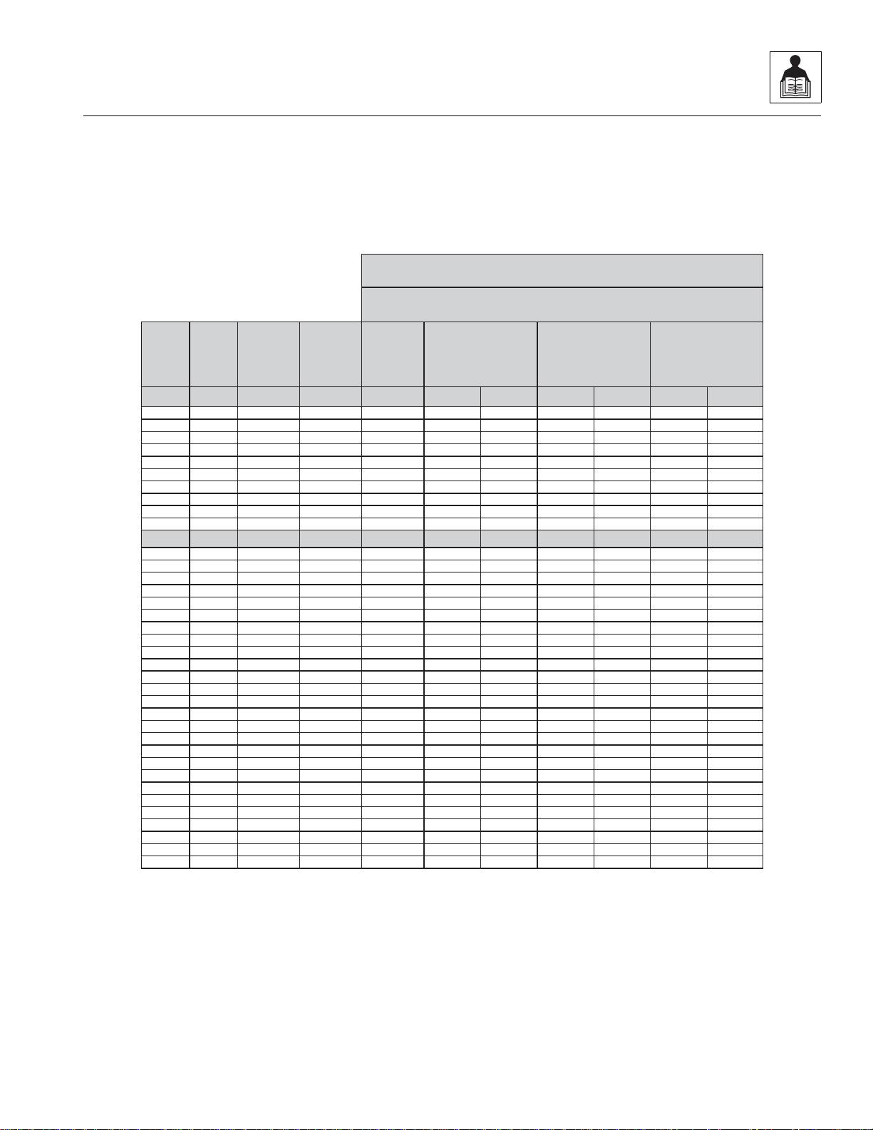
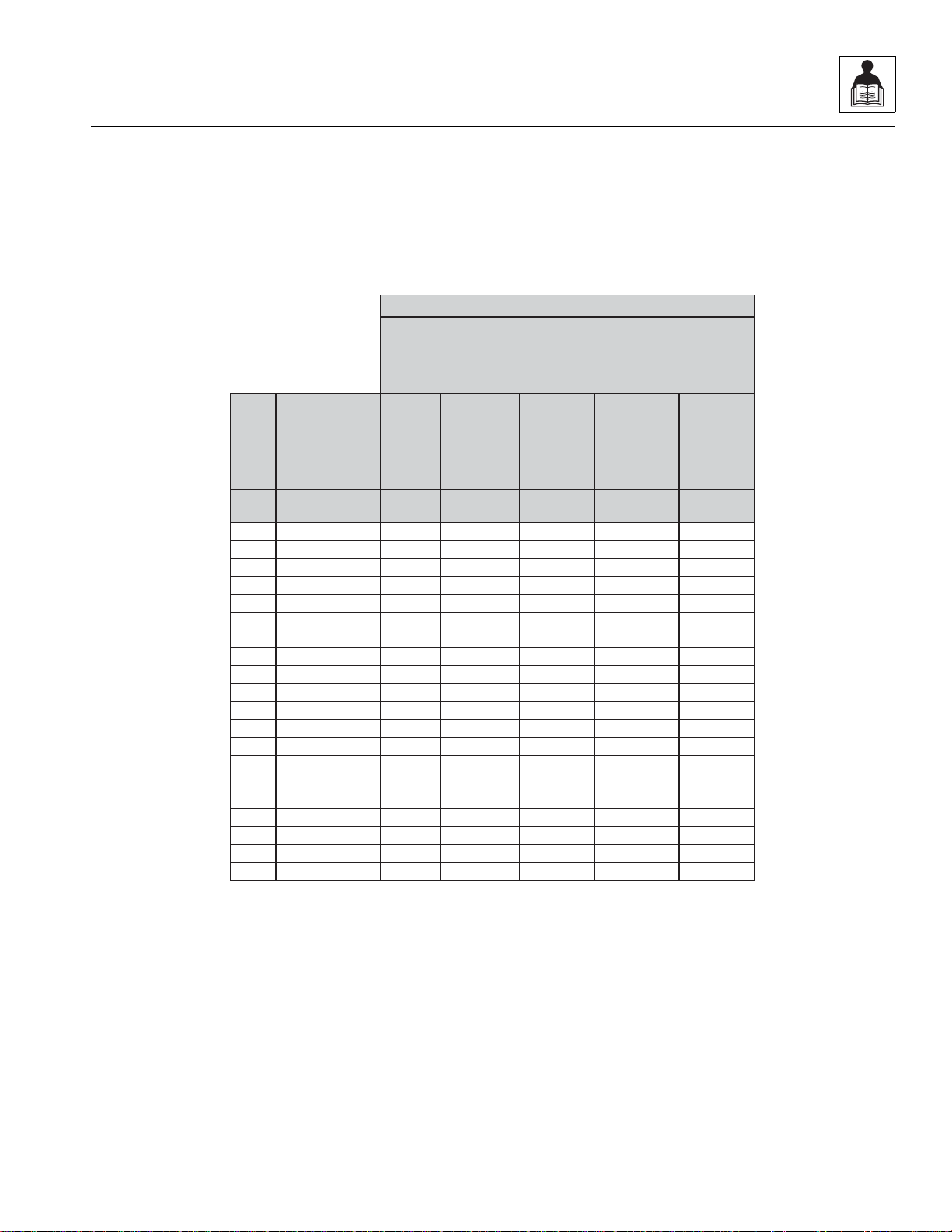
2.2.1 SAE Fastener Torque Chart
General Information and Specifications
944E-42
2-3
Page 16

General Information and Specifications
Size TPI Bolt Dia
Tensile
Stress Area
Clamp Load
In Sq In
4 40 0.1120 0.00604
48 0.1120 0.00661
6 32 0.1380 0.00909
40 0.1380 0.01015
8 32 0.1640 0.01400
36 0.1640 0.01474
10 24 0.1900 0.01750
32 0.1900 0.02000
1/4 20 0.2500 0.0318
28 0.2500 0.0364
In Sq In
5/16 18 0.3125 0.0524
24 0.3125 0.0580
3/8 16 0.3750 0.0775
24 0.3750 0.0878
7/16 14 0.4375 0.1063
20 0.4375 0.1187
1/2 13 0.5000 0.1419
20 0.5000 0.1599
9/16 12 0.5625 0.1820
18 0.5625 0.2030
5/8 11 0.6250 0.2260
18 0.6250 0.2560
3/4 10 0.7500 0.3340
16 0.7500 0.3730
7/8 9 0.8750 0.4620
14 0.8750 0.5090
1 8 1.0000 0.6060
12 1.0000 0.6630
1 1/8 7 1.1250 0.7630
12 1.1250 0.8560
1 1/4 7 1.2500 0.9690
12 1.2500 1.0730
1 3/8 6 1.3750 1.1550
12 1.3750 1.3150
1 1/2 6 1.5000 1.4050
12 1.5000 1.5800
Values for Zinc Yellow Chromate Fasteners
3. *ASSEMBLYUSES HARDENED WASHER
NOTES: 1. THESE TORQUE VALUES DO NOT APPLY TO CADMIUM PLATED FASTENERS
2. ALL TORQUE VALUESARE STATIC TORQUE MEASURED PER STANDARDAUDIT METHODS TOLERANCE = ±10%
LB IN-LB [N.m] IN-LB [N.m] IN-LB [N.m]
1320 43 5
1580 60 7
1800 68 8
2860 143 16 129 15
3280 164 19 148 17
LB FT-LB [N.m] FT-LB [N.m] FT-LB [N.m
4720 25 35 20 25 20 25
5220 25 35 25 35 20 25
7000 45 60 40 55 35 50
7900 50 70 45 60 35 50
9550 70 95 65 90 50 70
10700 80 110 70 95 60 80
12750 105 145 95 130 80 110
14400 120 165 110 150 90 120
16400 155 210 140 190 115 155
18250 170 230 155 210 130 175
20350 210 285 190 260 160 220
23000 240 325 215 290 180 245
30100 375 510 340 460 280 380
33600 420 570 380 515 315 430
41600 605 825 545 740 455 620
45800 670 910 600 815 500 680
51500 860 1170 770 1045 645 875
59700 995 1355 895 1215 745 1015
68700 1290 1755 1160 1580 965 1310
77000 1445 1965 1300 1770 1085 1475
87200 1815 2470 1635 2225 1365 1855
96600 2015 2740 1810 2460 1510 2055
104000 2385 3245 2145 2915 1785 2430
118100 2705 3680 2435 3310 2030 2760
126500 3165 4305 2845 3870 2370 3225
142200 3555 4835 3200 4350 2665 3625
K=.18
K=0.15
SAE GRADE 8 (HEX HD) BOLTS & GRADE 8 NUTS*
Torque
(Dry or Loctite® 263)
K= 0.20
MY4660J
Torque
Loctite® 262™
OR
Vibra-TITE™ 131
Torque
Loctite® 242™ or 271™
OR
Vibra-TITE™ 111 or 140
2.2.1 SAE Fastener Torque Chart
(Continued)
2-4
944E-42
Page 17
General Information and Specifications
Size TPI Bolt Dia
Tensile
Stress Area
Clamp Load
See Note 4
In Sq In LB IN-LB [N.m] IN-LB [N.m] IN-LB [N.m]
4 40 0.1120 0.00604
48 0.1120 0.00661
6 32 0.1380 0.00909
40 0.1380 0.01015
8 32 0.1640 0.01400
36 0.1640 0.01474
10 24 0.1900 0.01750
32 0.1900 0.02000
1/4 20 0.2500 0.0318 2860 122 14 114 13
28 0.2500 0.0364 3280 139 16 131 15
In Sq In LB FT-LB [N.m] FT-LB [N.m] FT-LB [N.m]
5/16 18 0.3125 0.0524 4720 20 25 20 25 20 25
24 0.3125 0.0580 5220 25 35 20 25 20 25
3/8 16 0.3750 0.0775 7000 35 50 35 50 35 50
24 0.3750 0.0878 7900 40 55 40 55 35 50
7/16 14 0.4375 0.1063 9550 60 80 55 75 50 70
20 0.4375 0.1187 10700 65 90 60 80 60 80
1/2 13 0.5000 0.1419 12750 90 120 85 115 80 110
20 0.5000 0.1599 14400 100 135 95 130 90 120
9/16 12 0.5625 0.1820 16400 130 175 125 170 115 155
18 0.5625 0.2030 18250 145 195 135 185 130 175
5/8 11 0.6250 0.2260 20350 180 245 170 230 160 220
18 0.6250 0.2560 23000 205 280 190 260 180 245
3/4 10 0.7500 0.3340 30100 320 435 300 410 280 380
16 0.7500 0.3730 33600 355 485 335 455 315 430
7/8 9 0.8750 0.4620 41600 515 700 485 660 455 620
14 0.8750 0.5090 45800 570 775 535 730 500 680
1 8 1.0000 0.6060 51500 730 995 685 930 645 875
12 1.0000 0.6630 59700 845 1150 795 1080 745 1015
1 1/8 7 1.1250 0.7630 68700 1095 1490 1030 1400 965 1310
12 1.1250 0.8560 77000 1225 1665 1155 1570 1085 1475
1 1/4 7 1.2500 0.9690 87200 1545 2100 1455 1980 1365 1855
12 1.2500 1.0730 96600 1710 2325 1610 2190 1510 2055
1 3/8 6 1.3750 1.1550 104000 2025 2755 1905 2590 1785 2430
12 1.3750 1.3150 118100 2300 3130 2165 2945 2030 2760
1 1/2 6 1.5000 1.4050 126500 2690 3660 2530 3440 2370 3225
12 1.5000 1.5800 142200 3020 4105 2845 3870 2665 3625
4. CLAMP LOAD LISTED FOR SHCS IS SAMEAS GRADE 8 OR CLASS 10.9AND DOES NOT REPRESENT FULLSTRENGTH
CAPABILITYOF SHCS. IF HIGHER LOAD IS REQUIRED, ADDITIONALTESTING IS REQUIRED.
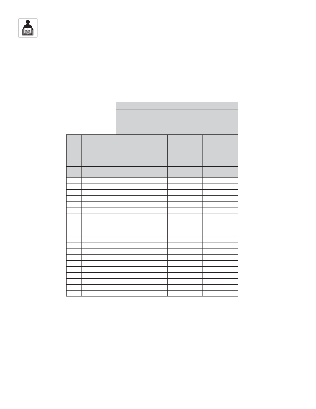
SOCKET HEAD CAP SCREWS
Magni Coating*
Torque
(Dry) K = .17
K=0.16
K=0.15
2. ALL TORQUE VALUESARE STATIC TORQUE MEASURED PER STANDARDAUDIT METHODS TOLERANCE = ±10%
NOTES: 1. THESE TORQUE VALUES DO NOT APPLY TO CADMIUM PLATED FASTENERS
*3. ASSEMBLY USES HARDENED WASHER OR FASTENER IS PLACED AGAINST PLATED STEEL OR RAW ALUMINUM
MY4670J
Torque
Loctite® 262™
OR
Vibra-TITE™ 131
Torque
Loctite® 242™ or 271™
OR
Vibra-TITE™ 111 or 140
OR Precoat 85®
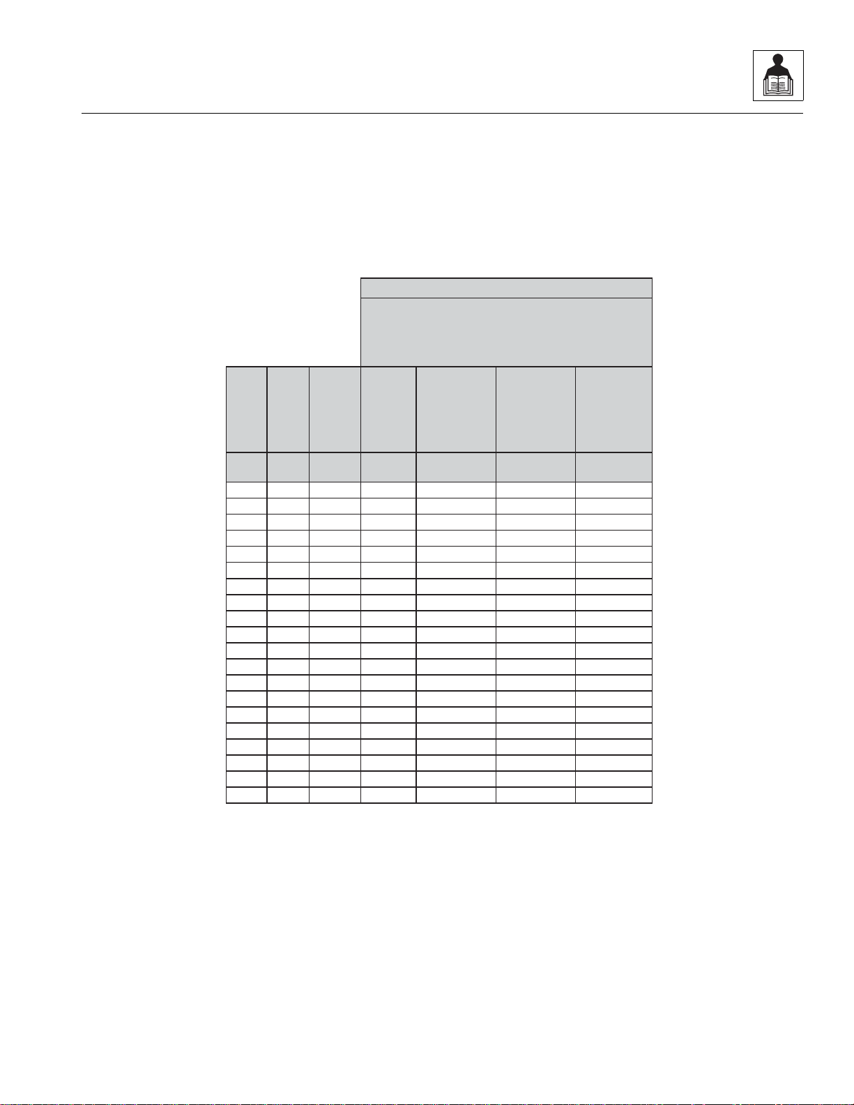
2.2.1 SAE Fastener Torque Chart
(Continued)
944E-42
2-5
Page 18
General Information and Specifications
Size TPI Bolt Dia
Tensile
Stress Area
Clamp Load
See Note 4
In Sq In LB IN-LB [N.m] IN-LB [N.m] IN-LB [N.m]
4 40 0.1120 0.00604
48 0.1120 0.00661
6 32 0.1380 0.00909
40 0.1380 0.01015
8 32 0.1640 0.01400
36 0.1640 0.01474
10 24 0.1900 0.01750
32 0.1900 0.02000
1/4 20 0.2500 0.0318 2860 143 16 129 15
28 0.2500 0.0364 3280 164 19 148 17
In Sq In LB FT-LB [N.m] FT-LB [N.m] FT-LB [N.m]
5/16 18 0.3125 0.0524 4720 25 35 20 25 20 25
24 0.3125 0.0580 5220 25 35 25 35 20 25
3/8 16 0.3750 0.0775 7000 45 60 40 55 35 50
24 0.3750 0.0878 7900 50 70 45 60 35 50
7/16 14 0.4375 0.1063 9550 70 95 65 90 50 70
20 0.4375 0.1187 10700 80 110 70 95 60 80
1/2 13 0.5000 0.1419 12750 105 145 95 130 80 110
20 0.5000 0.1599 14400 120 165 110 150 90 120
9/16 12 0.5625 0.1820 16400 155 210 140 190 115 155
18 0.5625 0.2030 18250 170 230 155 210 130 175
5/8 11 0.6250 0.2260 20350 210 285 190 260 160 220
18 0.6250 0.2560 23000 240 325 215 290 180 245
3/4 10 0.7500 0.3340 30100 375 510 340 460 280 380
16 0.7500 0.3730 33600 420 570 380 515 315 430
7/8 9 0.8750 0.4620 41600 605 825 545 740 455 620
14 0.8750 0.5090 45800 670 910 600 815 500 680
1 8 1.0000 0.6060 51500 860 1170 775 1055 645 875
12 1.0000 0.6630 59700 995 1355 895 1215 745 1015
1 1/8 7 1.1250 0.7630 68700 1290 1755 1160 1580 965 1310
12 1.1250 0.8560 77000 1445 1965 1300 1770 1085 1475
1 1/4 7 1.2500 0.9690 87200 1815 2470 1635 2225 1365 1855
12 1.2500 1.0730 96600 2015 2740 1810 2460 1510 2055
1 3/8 6 1.3750 1.1550 104000 2385 3245 2145 2915 1785 2430
12 1.3750 1.3150 118100 2705 3680 2435 3310 2030 2760
1 1/2 6 1.5000 1.4050 126500 3165 4305 2845 3870 2370 3225
12 1.5000 1.5800 142200 3555 4835 3200 4350 2665 3625
4. CLAMP LOAD LISTED FOR SHCS IS SAMEAS GRADE 8 OR CLASS 10.9AND DOES NOT REPRESENT FULLSTRENGTH
CAPABILITYOF SHCS. IF HIGHER LOAD IS REQUIRED, ADDITIONALTESTING IS REQUIRED.
SOCKET HEAD CAP SCREWS
Torque
(Dry)
K = .20
Torque
(Loctite® 242TMor 271
TM
OR Vibra-TITETM111 or
140 OR Precoat 85®
K=0.18
Zinc Yellow Chromate Fasteners*
2. ALL TORQUE VALUESARE STATIC TORQUE MEASURED PER STANDARDAUDIT METHODS TOLERANCE = ±10%
NOTES: 1. THESE TORQUE VALUES DO NOT APPLY TO CADMIUM PLATED FASTENERS
*3. ASSEMBLY USES HARDENED WASHER OR FASTENER IS PLACED AGAINST PLATED STEEL OR RAW ALUMINUM
Torque
(Loctite® 262
TM
or Vibra-
TITE
TM
131)
K=0.15
MY4680J
2.2.1 SAE Fastener Torque Chart
(Continued)
2-6
944E-42
Page 19
2.2.2 Metric Fastener Torque Chart
Size PITCH
Tensile
Stress
Area
Clamp
Load
Torque
(Dry or Loctite®
263
TM
)
Torque
(Lub)
Sq mm KN [N.m] [N.m] [N.m] [N.m]
3 0.5 5.03 2.19 1.3 1.0 1.2 1.4
3.5 0.6 6.78 2.95 2.1 1.6 1.9 2.3
4 0.7 8.78 3.82 3.1 2.3 2.8 3.4
5 0.8 14.20 6.18 6.2 4.6 5.6 6.8
6 1 20.10 8.74 11 7.9 9.4 12
7 1 28.90 12.6 18 13 16 19
8 1.25 36.60 15.9 26 19 23 28
10 1.5 58.00 25.2 50 38 45 55
12 1.75 84.30 36.7 88 66 79 97
14 2 115 50.0 140 105 126 154
16 2 157 68.3
219 164 197 241
18 2.5 192 83.5 301 226 271 331
20 2.5 245 106.5 426 320 383 469
22 2.5 303 132.0 581 436 523 639
24 3 353 153.5 737 553 663 811
27 3 459 199.5 1080 810 970 1130
30 3.5 561 244.0 1460 1100 1320 1530
33 3.5 694 302.0 1990 1490 1790 2090
36 4 817 355.5 2560 1920 2300 2690
42 4.5 1120 487.0 4090 3070 3680 4290
4. CLAMP LOAD LISTED FOR SHCS IS SAMEAS GRADE 8 OR CLASS 10.9AND DOES NOT
REPRESENT FULL STRENGTH CAPABILITY OF SHCS. IF HIGHER LOAD IS REQUIRED,
ADDITIONAL TESTING IS REQUIRED.
*3. ASSEMBLY USES HARDENED WASHER OR FASTENER IS PLACED AGAINST PLATED
STEEL OR RAW ALUMINUM
Values for Zinc Yellow Chromate Fasteners
CLASS 8.8 METRIC BOLTS
CLASS 8 METRIC NUTS
NOTES: 1. THESE TORQUE VALUES DO NOT APPLY TO CADMIUM PLATED FASTENERS
2. ALL TORQUE VALUESARE STATIC TORQUE MEASURED PER STANDARDAUDIT
METHODS TOLERANCE = ±10%
MY4690J
Torque
Loctite® 262™
OR
Vibra-TITE™ 131
Torque
Loctite®
242™ or 271™
OR
Vibra-TITE™
111 or 140
General Information and Specifications
944E-42
2-7
Page 20
General Information and Specifications
Size PITCH
Tensile
Stress
Area
Clamp
Load
K = 0.20
K= 0.18
K=0.15
Sq mm KN [N.m] [N.m] [N.m]
3 0.5 5.03 3.13
3.5 0.6 6.78 4.22
4 0.7 8.78 5.47
5 0.8 14.20 8.85
6 1 20.10 12.5
7 1 28.90 18.0 25.2 22.7 18.9
8 1.25 36.60 22.8 36.5 32.8 27.4
10 1.5 58.00 36.1 70 65 55
12 1.75 84.30 52.5 125 115 95
14 2 115 71.6 200 180 150
16 2 157 97.8
315 280 235
18 2.5 192 119.5 430 385 325
20 2.5 245 152.5 610 550 460
22 2.5 303 189.0 830 750 625
24 3 353 222.0 1065 960 800
27 3 459 286.0 1545 1390 1160
30 3.5 561 349.5 2095 1885 1575
33 3.5 694 432.5 2855 2570 2140
36 4 817 509.0 3665 3300 2750
42 4.5 1120 698.0 5865 5275 4395
Values for Zinc Yellow Chromate Fasteners
CLASS 10.9 METRIC BOLTS
CLASS 10 METRIC NUTS
CLASS 12.9 SOCKET HEAD CAP SCREWS M3 - M5*
4. CLAMP LOAD LISTED FOR SHCS IS SAMEAS GRADE 8 OR CLASS 10.9AND DOES NOT
REPRESENT FULL STRENGTH CAPABILITY OF SHCS. IF HIGHER LOAD IS REQUIRED,
ADDITIONAL TESTING IS REQUIRED.
*3. ASSEMBLY USES HARDENED WASHER OR FASTENER IS PLACED AGAINST PLATED
STEEL OR RAW ALUMINUM
NOTES: 1. THESE TORQUE VALUES DO NOT APPLY TO CADMIUM PLATED FASTENERS
2. ALL TORQUE VALUESARE STATIC TORQUE MEASURED PER STANDARDAUDIT
METHODS TOLERANCE = ±10%
MY4700J
Torque
Loctite® 262™
OR
Vibra-TITE™ 131
Torque Dry
or
Loctite® 263™
Torque
Lube OR Loctite®
242™ or 271™
OR
Vibra-TITE™
111 or 140
2.2.2 Metric Fastener Torque Chart
(Continued)
2-8
944E-42
Page 21
2.2.2 Metric Fastener Torque Chart
Size PITCH
Tensile
Stress
Area
Clamp Load
See Note 4
K = .17
K = .16
K = .15
Sq mm kN [N.m] [N.m] [N.m]
3 0.5 5.03
3.5 0.6 6.78
4 0.7 8.78
5 0.8 14.20
6 1 20.10 12.5 13 12 11
7 1 28.90 18.0 21 20 19
8 1.25 36.60 22.8 31 29 27
10 1.5 58.00 36.1 61 58 54
12 1.75 84.30 52.5 105 100 95
14 2 115 71.6 170 160 150
16 2 157
97.8 265 250 235
18 2.5 192 119.5 365 345 325
20 2.5 245 152.5 520 490 460
22 2.5 303 189.0 705 665 625
24 3 353 220.0 900 845 790
27 3 459 286.0 1315 1235 1160
30 3.5 561 349.5 1780 1680 1575
33 3.5 694 432.5 2425 2285 2140
36 4 817 509.0 3115 2930 2750
42 4.5 1120 698.0 4985 4690 4395
CLASS 12.9 SOCKET HEAD CAP SCREWS
M6 AND ABOVE*
4. CLAMP LOAD LISTED FOR SHCS IS SAMEAS GRADE 8 OR CLASS 10.9AND DOES NOT
REPRESENT FULL STRENGTH CAPABILITY OF SHCS. IF HIGHER LOAD IS REQUIRED,
ADDITIONAL TESTING IS REQUIRED.
*3. ASSEMBLY USES HARDENED WASHER OR FASTENER IS PLACED AGAINST PLATED
STEEL OR RAW ALUMINUM
NOTES: 1. THESE TORQUE VALUES DO NOT APPLY TO CADMIUM PLATED FASTENERS
2. ALL TORQUE VALUESARE STATIC TORQUE MEASURED PER STANDARDAUDIT
METHODS TOLERANCE = ±10%
Magni Coating*
MY4710J
Torque
Loctite® 262™
OR
Vibra-TITE™ 131
Torque
Lube OR Loctite®
242™ or 271™
OR
Vibra-TITE™
111 or 140
Torque Dry
or
Loctite® 263™
(Continued)
General Information and Specifications
944E-42
2-9
Page 22

General Information and Specifications
2.2.3 Hydraulic Hose Torque Chart
O-Ring Face Seal & JIC Torque Chart
Size ORFS JIC Flats Method
4
6
8
10
12
16
20
24
13 lb-ft
(18 Nm)
23 lb-ft
(31 Nm)
40 lb-ft
(54 Nm)
60 lb-ft
(81 Nm)
74 lb-ft
(100 Nm)
115 lb-ft
(156 Nm)
170 lb-ft
(230 Nm)
200 lb-ft
(271 Nm)
13 lb-ft
(18 Nm)
23 lb-ft
(31 Nm)
40 lb-ft
(54 Nm)
60 lb-ft
(81 Nm)
85 lb-ft
(115 Nm)
115 lb-ft
(156 Nm)
170 lb-ft
(230 Nm)
200 lb-ft
(271 Nm)
1.5 to 1.75
1 to 1.5
1.5 to 1.75
1.5 to 1.75
1.0 to 1.5
0.75 to 1.0
0.75 to 1.0
0.75 to 1.0
Flats Method:
1. If equipped, lubricate o-ring with hydraulic oil. Hand
tighten the swivel nut until no lateral movement of
the swiv el nut can be detected. A v e rage hand torque
is 3 lb-ft (4 Nm).
2. Mark a dot on one of the swivel nut fla ts and another
dot in line on the hex of the adapter it’s connecting
to.
3. Use the double wrench method while tightening to
avoid hose twist.
4. After the connection has been properly tightene d,
mark a straight line across the connecting parts, not
covering the dots indicating that the connection has
been properly tightened.
32 N/A
Note: By definition the “Flats Method“ will contain some
variance. Use the “Flats Method” only when accessibility
with a torque wrench is not possible.
Torque Wrench:
1. Identify the appropriate application and refer to the
above chart for the correct torque value.
2. If equipped, lubricate o-ring with hydraulic oil. Hand
tighten the swivel nut until no lateral movement of
the swiv el nut can be detected. A v erage hand torque
is 3 lb-ft (4 Nm).
3. Use the double wrench method while tightening to
avoid hose twist.
4. Torque wrench mu st be held at th e center of the g rip.
Apply constant force until it clicks.
5. After the connection has been properly tightened,
mark a straight line across the connecting parts
indicating that the connection has been properly
tightened.
270 lb-ft
(366 Nm)
0.75 to 1.0
2-10
944E-42
Page 23

General Information and Specifications
2.3 SPECIFICATIONS
2.3.1 Travel Speeds
First Gear 3.5 mph (5,6 km/hr)
Second Gear 6 mph (9,7 km/hr)
Third Gear 14 mph (23 km/hr)
Fourth Gear 20 mph (32 km/hr)
2.3.2 Hydraulic Cylinder Performance
Note: Machine with no attachment or load, engine at full throttle, hydraulic oil above 130° F (54° C) mi nimum, engine
at operating temperature.
Function Approximate Times, in Seconds
Boom Extend (boom level) 11 to 15
Boom Retract (boom level) 13 to 17
Boom Lift (boom retracted) 11 to 15
Boom Lower (boom retracted) 11 to 15
Quick Attach Tilt Up 2.5 to 3.5
Quick Attach Tilt Down 3 to 5
Transfer Carriage Forward (boom retracted and level) 9 to 14
Transfer Carriage Rearward (boom retracted and level) 9 to 13
Frame Sway Left to Right (boom retracted and level) 9 to 11
Frame Sway Left to Right
(boom retracted, raised above 40
Fram e Sway Right to Left (boom retracted and level) 9 to 11
Frame Sway Right to Left
(boom retracted, raised above 40
° and emergency brake engaged)
° and emergency brake engaged)
26 to 30
26 to 30
2.3.3 Electrical System
Battery
Type, Rating 12 VDC, Negative (-) Ground, Maintenance Free
Quantity 2
Reserve Capacity 850 Cold Cranking Amps @ 0° F (-18° C)
Group/Series Group 27
Alternator 12V, 100 Amps
944E-42
2-11
Page 24

General Information and Specifications
2.3.4 Engine Performance Specifications
Note: Engine manufacturer's maximum “high idle” setting is lockwired and sealed. DO NOT disturb this setting
Engine Make/Model Cummins QSB 4.5
Displacement 275 in
3
(4.5 liters)
Low Idle 950 rpm
High Idle 2500 rpm
Horsepower 110 hp (82 Kw) @ 2500 rpm
Peak Torque 360 lb-ft (4488 Nm) @ 1500 rpm
Fuel Delivery Fuel Injection
Air Cleaner Dry Type, Replaceable Primary and Safety Elements
2.3.5 Tires
Note: Standard wheel lug nut torque is 430-470 lb-ft (583-637 Nm).
15.50 x 25 G-2/L-2 Bias-Ply Traction 12 Ply
15.50 x 25 G-2/L-2 Radial 1 Star
15.50 x 25 G-3/L-3 Bias-Ply Rock 12 Ply
370/75x28 DuraForce 14 Ply
Pneumatic 65 psi (4,5 bar)
Foam 798 lb (362 kg)
Pneumatic 65 psi (4,5 bar)
Foam 798 lb (362 kg)
Pneumatic 65 psi (4,5 bar)
Foam 798 lb (362 kg)
Pneumatic 76 psi (5,2 bar)
Foam-Approx 464 lb
(210 kg)
73 psi (5,0 bar)
2-12
944E-42
Page 25

General Information and Specifications
2.4 FLUID AND LUBRICANT CAPACITIES
Engine Crankcase Oil
Capacity with Filter Change 13.5 quarts (12.8 liters)
Type of Oil
0° to 104° F (-20° to 40° C) 15W-40 CD
-40° to 0° F (-40° to 20° C) 0W-40 CD
Fuel Tank
Capacity 45 gallons (171 liters)
Type of Fuel
0° to 104° F (-20° to 40° C) #2 Diesel
-40° to 0° F (-40° to 20° C) #1 Diesel
Anti-Gel
-40° to 0° F (-40° to 20° C) 16 ounces (0,5 liters)
Cooling System
System Capacity W/O Heater 7.7 gallons (29,1 liters)
Type of Coolant 50/50 ethylene glycol & water
Hydraulic System
System Capacity 50 gallons (190 liters)
Reservoir Capacity 34 gallons (127 liters)
Type of Fluid Mobilfluid 424
®
Tractor Hydraulic Fluid (ISO 46)
Transmission
Capacity with Filter Change 4.2 gallons (16 liters)
Type of Fluid Mobilfluid 424
®
Tractor Hydraulic Fluid (ISO 46)
Transfer Case
Capacity 1.7 quarts (1,6 liters)
Type of Fluid Mobilfluid 424
®
Tractor Hydraulic Fluid (ISO 46)
Axles
Differential Housing Capacity
Front 12.7 quarts (12,0 liters)
Rear 12.5 quarts (11,8 liters)
Wheel End Capacity
Front 2.1 quarts (2,0 liters)
Rear 2.2 quarts (2,1 liters)
Type of Fluid Mobilfluid 424
944E-42
®
Tractor Hydraulic Fluid (ISO 46)
2-13
Page 26

General Information and Specifications
Air Conditioning System (if equipped)
System Capacity 2.5 lb (1134 g)
Type of Fluid Refrigerant R-134a - Tetrafluorethane
Window Washer Bottle
Capacity 2.1 quart (2 liters)
2-14
944E-42
Page 27
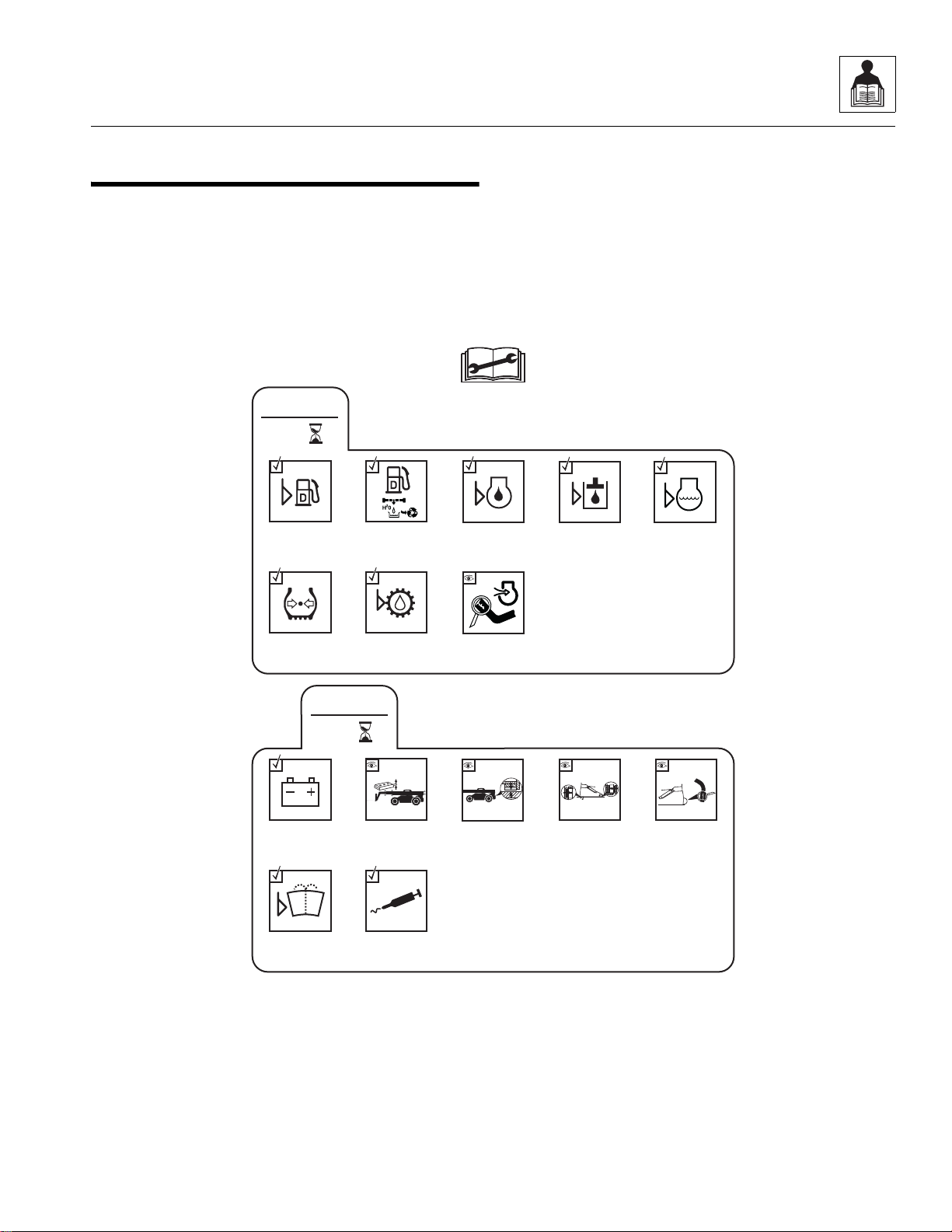
2.5 SERVICE AND MAINTENANCE
MU7640
Check Boom
Wear Pads
Check
Battery
Lubrication
Schedule
Check Transfer
Carriage Rear
Wear Pads
Check Transfer
Carriage
Roller Gap
Check Transfer
Carriage Roll
Back Hoses
Check Air
Intake System
Check
Transmission
Oil Level
10
EVERY
Check Fuel
Level
Check Hydraulic
Oil Level
Check Engine
Oil Level
Check Engine
Coolant Level
Check Tire
Condition &
Pressure
Drain Fuel/
Water Seprator
50
EVERY
Check Washer
Fluid Level
(if equipped)
SCHEDULES
2.5.1 10 & 50 Hour
General Information and Specifications
944E-42
2-15
Page 28
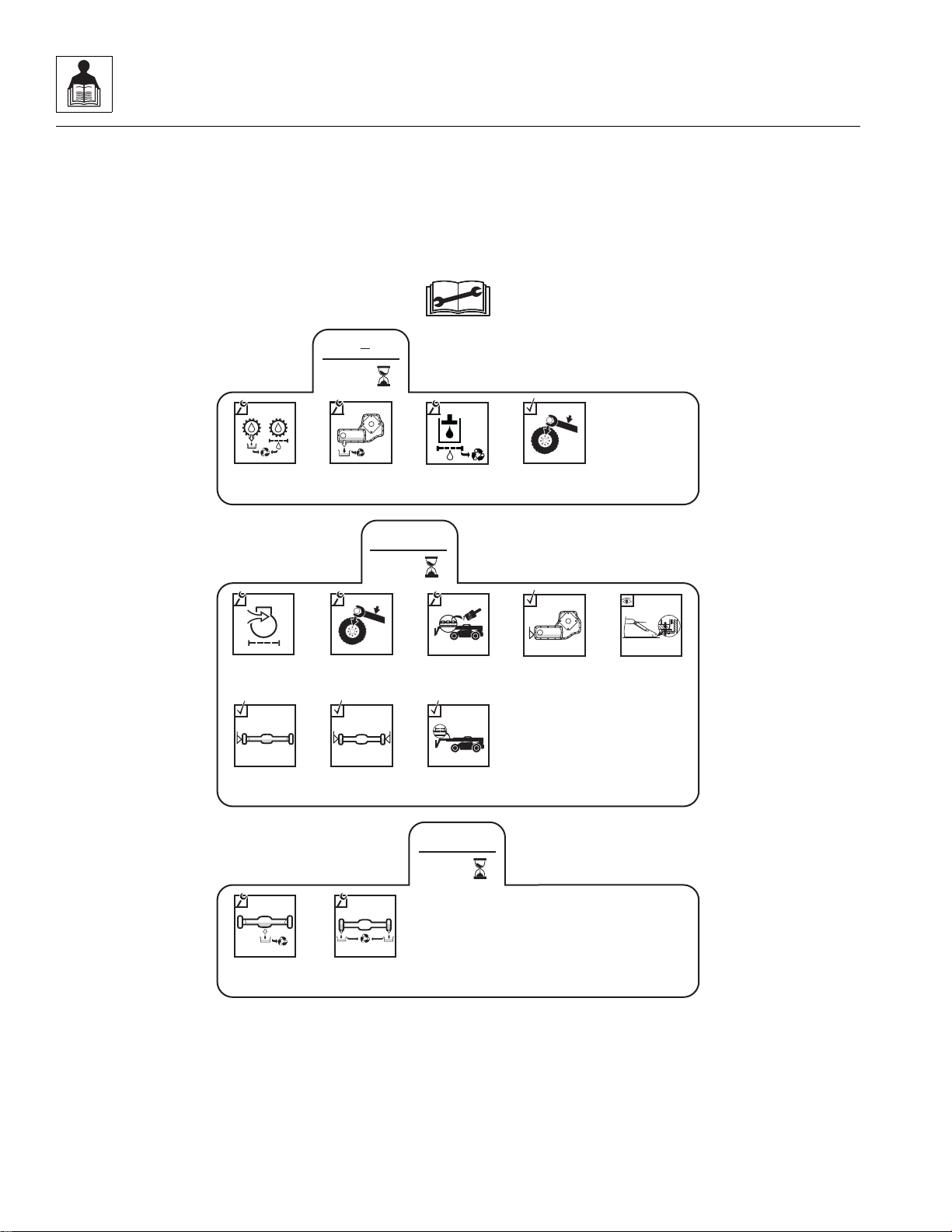
General Information and Specifications
MU7300
500
1
st
Change
Axle Oil
Change Wheel
End Oil
100
1
st
Change
Hydraulic
Filters
Check Wheel
Lug Nut
Torque
LB/FT (Nm)
Change
Transfer
Case Oil
Change
Transmission
Oil and Filter
250
EVERY
Check Wheel
Lug Nut
Torque
LB/FT (Nm)
Check Axle
Oil Level
Check Wheel
End Oil Levels
Check Transfer
Case Oil Level
Check Transfer
Carriage Front
Upstop Wear Pads
Change Air
Filter Elements
Check Boom
Extend Chains
and Tension
Lubricate
Boom Extend
Chains
2.5.2 1st 100, 250 & 1st 500 Hour
2-16
944E-42
Page 29
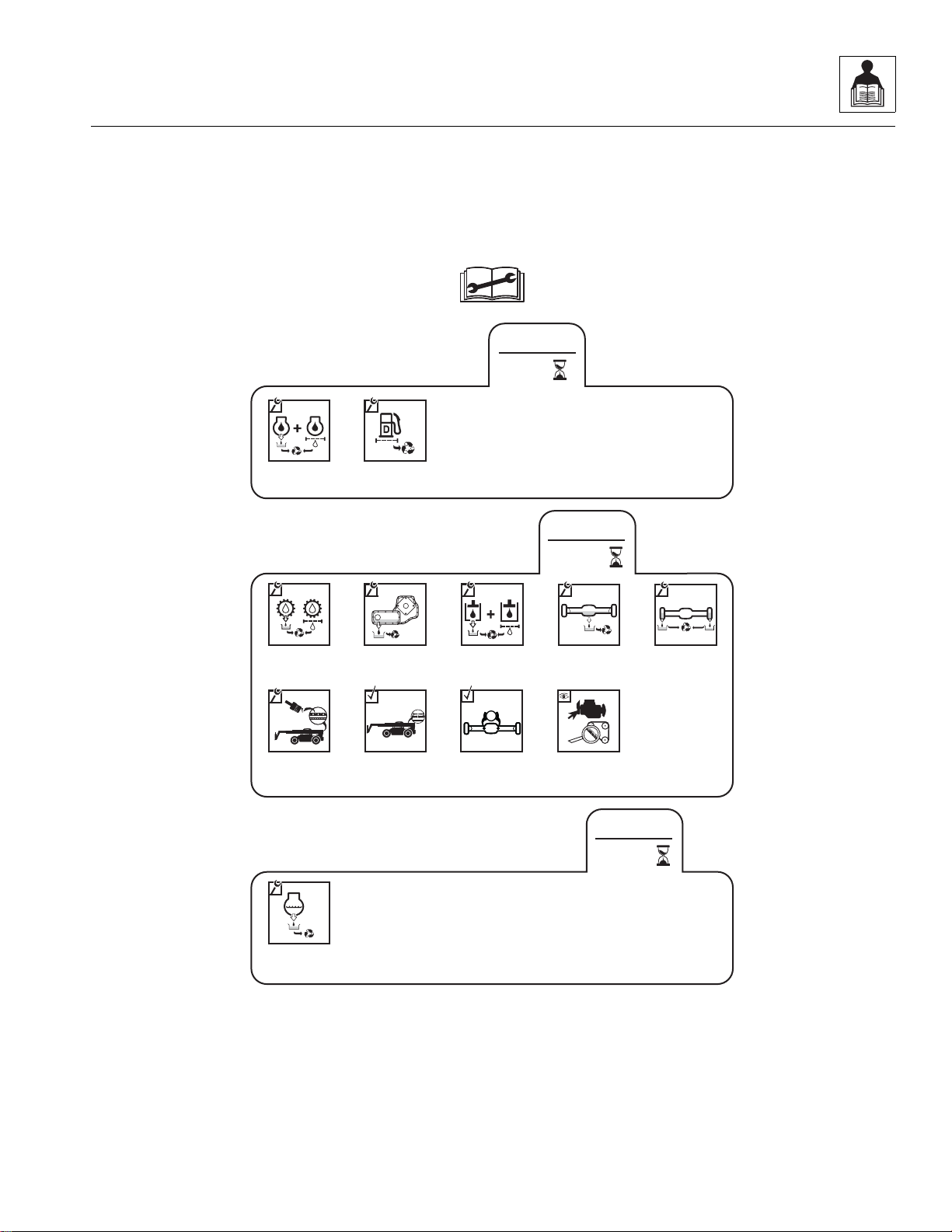
2.5.3 500, 1000 & 2000 Hour
MU7650
2000
EVERY
Change
Engine Coolant
500
EVERY
Change Fuel
Filters
Change Engine
Oil and Filter
1000
EVERY
Change
Transmission
Oil and Filter
Change
Axle Oil
Change Wheel
End Oil
Change
Hydraulic
Fluid and Filters
Change
Transfer
Case Oil
Check
Fan Belt
Check Axle
Brake Discs
P
Check Boom
Retract Chains
and Tension
Lubricate
Boom Retract
Chains
General Information and Specifications
944E-42
2-17
Page 30
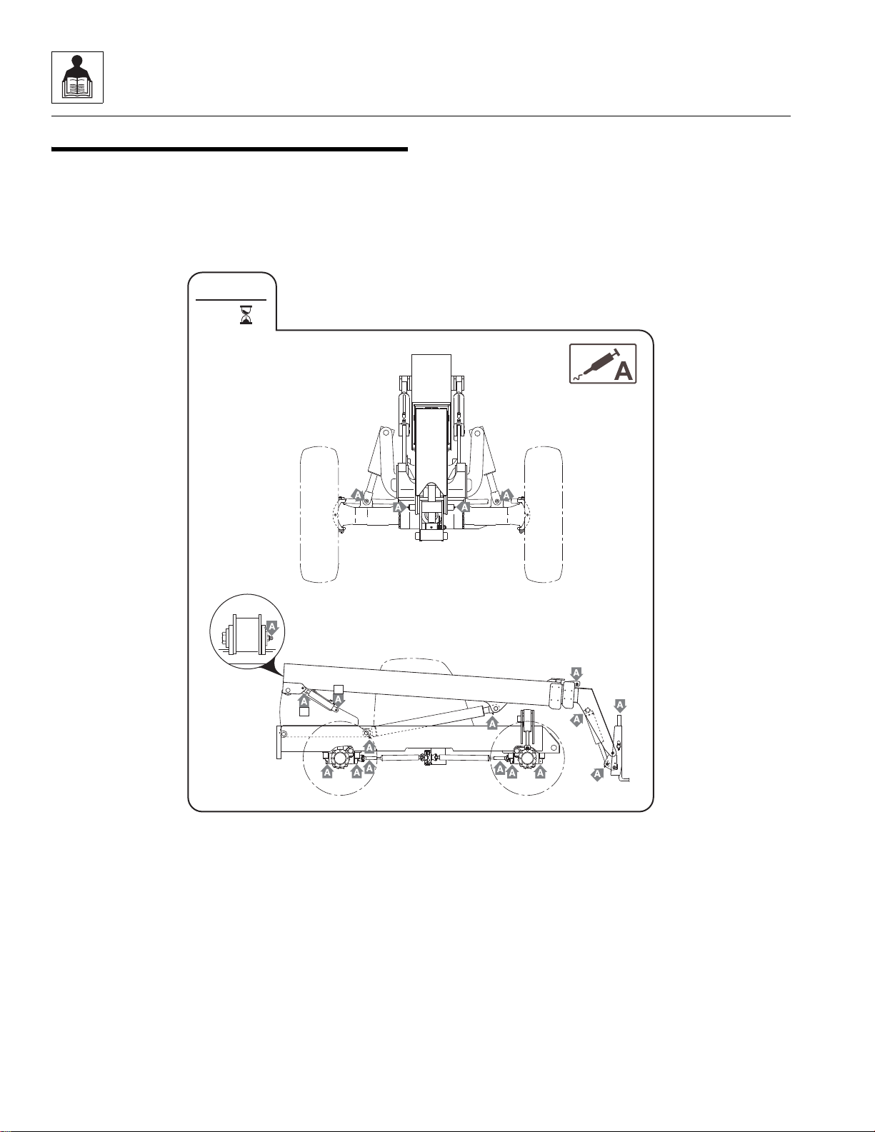
General Information and Specifications
OU2430
50
EVERY
2
2
2.6 LUBRICATION SCHEDULES
a. 50 Hour
2-18
944E-42
Page 31

Section 3
Boom
Contents
PARAGRAPH TITLE PAGE
3.1 Boom System Component Terminology. . . . . . . . . . . . . . . . . . . . . . . . . . . . . . . . 3-2
3.2 Boom System . . . . . . . . . . . . . . . . . . . . . . . . . . . . . . . . . . . . . . . . . . . . . . . . . . . . . 3-3
3.2.1 Boom System Operation. . . . . . . . . . . . . . . . . . . . . . . . . . . . . . . . . . . . . . 3-3
3.3 Boom Assembly Maintenance . . . . . . . . . . . . . . . . . . . . . . . . . . . . . . . . . . . . . . . . 3-3
3.3.1 Third Boom Section Removal . . . . . . . . . . . . . . . . . . . . . . . . . . . . . . . . . . 3-3
3.3.2 Second Boom Section Removal . . . . . . . . . . . . . . . . . . . . . . . . . . . . . . . . 3-7
3.3.3 First Boom Section Removal. . . . . . . . . . . . . . . . . . . . . . . . . . . . . . . . . . . 3-8
3.3.4 First Boom Section Installation . . . . . . . . . . . . . . . . . . . . . . . . . . . . . . . . . 3-10
3.3.5 Second Boom Section Installation . . . . . . . . . . . . . . . . . . . . . . . . . . . . . . 3-11
3.3.6 Third Boom Section Installation . . . . . . . . . . . . . . . . . . . . . . . . . . . . . . . . 3-11
3.4 Boom Extend and Retract Chains . . . . . . . . . . . . . . . . . . . . . . . . . . . . . . . . . . . . . 3-14
3.4.1 Boom Chain Inspection. . . . . . . . . . . . . . . . . . . . . . . . . . . . . . . . . . . . . . . 3-14
3.4.2 Inspection Guidelines . . . . . . . . . . . . . . . . . . . . . . . . . . . . . . . . . . . . . . . . 3-15
3.4.3 Expose Chains for Inspection . . . . . . . . . . . . . . . . . . . . . . . . . . . . . . . . . . 3-17
3.4.4 Chain Lubrication . . . . . . . . . . . . . . . . . . . . . . . . . . . . . . . . . . . . . . . . . . . 3-17
3.4.5 Boom Chain Tension Check . . . . . . . . . . . . . . . . . . . . . . . . . . . . . . . . . . . 3-17
3.4.6 Boom Chain Tension Adjustment . . . . . . . . . . . . . . . . . . . . . . . . . . . . . . . 3-18
3.4.7 Extend Chains Removal and Replacement . . . . . . . . . . . . . . . . . . . . . . . 3-20
3.4.8 Retract Chain Removal and Replacement . . . . . . . . . . . . . . . . . . . . . . . . 3-20
3.5 Boom Wear Pads. . . . . . . . . . . . . . . . . . . . . . . . . . . . . . . . . . . . . . . . . . . . . . . . . . . 3-22
3.5.1 Wear Pad Inspection. . . . . . . . . . . . . . . . . . . . . . . . . . . . . . . . . . . . . . . . . 3-22
3.5.2 Wear Pad Installation and Lubrication. . . . . . . . . . . . . . . . . . . . . . . . . . . . 3-22
3.6 Quick Attach Assembly . . . . . . . . . . . . . . . . . . . . . . . . . . . . . . . . . . . . . . . . . . . . . 3-23
3.6.1 Quick Attach Removal. . . . . . . . . . . . . . . . . . . . . . . . . . . . . . . . . . . . . . . . 3-23
3.6.2 Quick Attach Installation . . . . . . . . . . . . . . . . . . . . . . . . . . . . . . . . . . . . . . 3-23
3.7 Forks . . . . . . . . . . . . . . . . . . . . . . . . . . . . . . . . . . . . . . . . . . . . . . . . . . . . . . . . . . . .3-23
3.8 Troubleshooting . . . . . . . . . . . . . . . . . . . . . . . . . . . . . . . . . . . . . . . . . . . . . . . . . . . 3-24
3.9 Emergency Boom Lowering. . . . . . . . . . . . . . . . . . . . . . . . . . . . . . . . . . . . . . . . . . 3-27
3.9.1 Loss of Engine Power or Hydraulic Pump Failure. . . . . . . . . . . . . . . . . . . 3-27
3.9.2 Hydraulic Line Failure . . . . . . . . . . . . . . . . . . . . . . . . . . . . . . . . . . . . . . . . 3-27
3.9.3 Hydraulic Hose Replacement . . . . . . . . . . . . . . . . . . . . . . . . . . . . . . . . . . 3-28
3.9.4 Hydraulic Hose Replacement - Step 1 . . . . . . . . . . . . . . . . . . . . . . . . . . . 3-28
3.9.5 Hydraulic Hose Replacement - Step 2 . . . . . . . . . . . . . . . . . . . . . . . . . . . 3-29
944E-42
3-1
Page 32

Boom
MU0161
THIRD BOOM
SECTION
BOOM EXTEND
CHAINS
BOOM RETRACT
CHAIN
SECOND BOOM
SECTION
FIRST BOOM
SECTION
SLAVE
CYLINDERS
QUICK ATTACH
EXTEND/
RETRACT
ATTACHMENT
TILT HYDRAULIC
TUBES
ATTACHMENT
TILT CYLINDER
BOOM
PROXIMITY
SENSOR
AUXILIARY
HYDRAULIC
COUPLERS
WEAR PAD
BOOM ANGLE
INDICATOR
BOOM
PIVOT PIN
3.1 BOOM SYSTEM COMPONENT TERMINOLOGY
The following illustrations identify the components that
are referred to throughout this section.
3-2
944E-42
Page 33

Boom
MU0981
1
MU0221
2
4
3.2 BOOM SYSTEM
3.2.1 Boom System Operation
The three section boom assembly consists of first,
second and third boom section assemblies . Boom
extension and retraction is accomplished via hydraulic
power and chain movement.
As the Extend/Retract hydraulic cylinder, which is
anchored at the rear of the second b oom section and the
rear of the first boom section, begins to extend, it for ces
the second boom section out of the first boom section.
The second and third boom sections are connected by
extend and retract chains. These chains ar e routed
around sheaves on the second boom section. As the
second boom section is forced out, the extend ch ain pulls
the third boom section out of the second boom section.
As hydraulic pressure is applied to the retract po rt on the
extend/retract cylinder, the second bo om section is pulled
back into the first boom section, and retract cha in pu lls
the third boom section back into the second section.
This mechanical linkage formed by the chains and
supporting hardware extends and retracts the second
and third boom sections at the same rate.
The first boom section does not extend or retract, but lifts
and lowers via action of the lift/lower cylinder.
3.3.1 Third Boom Section Removal
1. Remove any attachment from the quick attach
assembly.
Note: If replacing the third section boom, remove the
quick attach from the third section. Refer to Section
3.6.1, “Quick Attach Removal.”
2. Park the machine on a hard, level surface, level the
machine, position the boom until it is extended
approximately 3 to 6 inches (76 to 152 mm), le vel the
boom, place the transmission control lever in
(N) NEUTRAL, engage the park brake and shut the
engine OFF.
3.3 BOOM ASSEMBLY MAINTENANCE
These instructions must be completed in sequence. The
third boom section must be re moved before removing the
second boom section. The third and second boom
section must be removed at one time before removin g the
first boom section.
Before beginning, conduct a visual inspection of the
machine and work area, and review the t ask abou t to be
undertaken. Read, understand and follow these
instructions.
NEVER weld or drill the boom unless approved in
writing by the manufacturer. The structural integrity of
the boom will be impaired if subjected to any repair
involving welding or drilling.
WARNING
3. At the front of the second boom section, remove the
top and side (1) wear pads. Label all parts for
installation.
4. Remove the rear boom cover.
944E-42
3-3
Page 34

Boom
MU0211
3
MU6061
5
6
5. Loosen the extend chain loc knut (2) a t the rear of the
boom halfway. The locknut must remain fully
engaged on the threads of the extend chain clevis.
6. In the cab, start the engine and retract the boom
slightly until slack is noticed in the extend chain.
Shut the engine OFF.
7. Move the attachment tilt joystick in both directions to
relieve an y trapped pressure in the system. Move the
auxiliary hydraulic joystick in both directions to
relieve any trapped pressure in the system.
8. Place a Do Not Operate Tag on both the igniti on key
switch and the steering wheel, stating that the
machine should not be operated.
9. Open the engine cover. Allow the system fluids to
cool.
10. Properly disconnect the batteries.
11. Remove the clevis pin (3) to disconnect the extend
chain yoke from the f irst boom section. La y the chain
assembly flat against the third boom section.
12. Label, disconnect and cap the hydraulic hoses (4)
attached to the Extend/Retract cylinder. Plug all
fittings to keep dirt & debris from en te ring the
hydraulic system.
13. Remove the one locknut, key plate, shim(s), flat
washer and capscrew on the left and right side of the
Extend/Retract cylinder rod trunnion mount (5).
Label all parts for installation.
14. Remove the capscrews and washers securing the
cylinder tube trunnion clamps to the seco nd boo m
section.
3-4
15. Remove the tie wraps from the two hose guards (6)
and remove the hose guards from the cylinder
hoses.
944E-42
Page 35

Boom
MU0221
7
8
MU1211
9
16. Label, disconnect and cap the attachment tilt hoses
at the fittings at the front of the third boom section.
Cap all fittings to keep dirt & debris from entering the
hydraulic system.
Note: If replacing the third boom section with a new
boom section; Remove the female coupler, male nipple
and bulkhead fittings from the bulkhead pl ate inside the
boom head.
Note: If the third boom section is equipped with remote
auxiliary hydraulic couplers, remove the couplers, tubes
and mounting plate from the boom head. Transfer the
couplers to the boom head of the new boom section.
17. Remove the capscrews holding the hose clamps to
their boom mounts at the rear of the third boom
section.
18. Use a suitable overhead lifting device and sling,
attach to the Extend/Retract cylinder trunnion (7).
Rotate and pull the cylinder out of the third boom
section far enough to give the attachment tilt and
auxiliary hydraulic hoses (8) enough room to be
pulled out of the boom.
19. Remove the attachment tilt and auxiliary hydraulic
hoses from the third boom section by pulling them
out from the top of the third boom section. Lay the
hoses behind the machine.
20. Completely remove the Extend/Retract cylinder.
Readjust the position of the sling as needed to help
balance the cylinder during withdraw. When the
cylinder is clear of the machine, carefully lower it to
the ground.
21. Remove the clevis pin (9) to disconnect the retract
chain yoke from the rear of the third boom section.
Lay the chain assembly f lat behind the third boom
section.
22. Install a lifting eye to the nut on the attachment tilt
cylinder. Attach a suitable overhead lifting device
and sling to the lifting eye.
23. Remove the pin from the attachme nt tilt cylin der and
lower the cylinder to the ground.
24. Use a suitable overhead lifting device and sling
attached to the third boom section; remove slack
from the hoist sling, and withdraw the boom 6 ft.
(2 m).
25. Remove the bottom wear pads at the front of the
second boom section. Label each part for
installation.
26. Pull the third boom section straight out of the second
boom section. Reposition the slings as needed so
the third boom section balances when remov ed from
the second boom section. Set the boom section
down on a hard, level surface. Support the boom as
needed to prevent it from tipping over.
944E-42
3-5
Page 36

Boom
MU5061
10
MU0261
11
12
MU1061
13
27. At the rear of the third boom section, remove the
remaining wear pads (10), shims and hardware.
Label all parts for installation.
28. Inspect all wear pads for wear. Refer to Section 3.5,
“Boom Wear Pads.”
30. Remove the hydr aulic hose r ack (13) inside the third
boom section.
29. At the rear of the third boom section, disconnect the
retract chain (11) from the anchor link (12).
3-6
944E-42
Page 37

3.3.2 Second Boom Section Removal
MU1221
14
15
MU4171
16
MU1431
17
1. At the front of the first boom section, remove the top
and side wear pads. Label all parts for installation.
2. At the rear of the boom, remove the sheave pin (14)
and sheave (15).
3. Use suitable overhead lifting device and sling to lift
the second boom section enough to gain access to
bottom wear pads. Remove the bottom wear pads.
Label all parts for installation.
4. Reposition the sling and continue pulling the second
boom section straight out of the first boom section.
Reposition the slings as needed so the second
boom section balances when removed from the first
boom section. Set the second boom section down
on blocks on a hard, level surface.
5. Remove the remaining wea r pads. Label all parts for
installation.
6. Inspect all wear pads for wear. Refer to Section 3.5,
“Boom Wear Pads.”
Boom
7. At the rear of the second boom section, remove the
two hose guides (16).
8. Remove the chain sheave (17).
944E-42
3-7
Page 38

Boom
MU1411
18
MU0281
19
MU0341
1
MU1291
2
3.3.3 First Boom Section Removal
1. At the front of the boom, remove the retract chain
locknut (18) and washer.
4. Pull the hydraulic hoses out of the boom. Label all
parts for installation.
2. Label, disconnect and cap the hydraulic hoses (19)
attached to the attachment tilt and auxiliary hydraulic
tubes. Plug all fitting to keep dirt & debris from
entering the hydraulic system.
3. Remove all clamps (1) securing the hydraulic tubes
and rear hydraulic hoses to the boom and frame.
Label and remove the tubes. Cap all hose ends.
3-8
5. Remove the boom proximity sensor (2) from the
boom.
944E-42
Page 39

Boom
MU0351
3
MU0371
4
6
5
9. Use a suitable overhead lifting device and sling to
support the boom.
6. Use a suitable overhead lifting device and sling (3) to
support the first boom section. Remove any slack
from the sling
7. Block up or support the lift/lower cylinder. Remove
the cylinder pin and carefully lower the cylinder onto
the support.
10. Remove the boom pivot pins (5) and shim washers
(6). Label all parts for installation.
11. Carefully lift the first boom section away from the
machine. Set the boom section down on a hard, le vel
surface.
8. Working on the top of each slave cylinder, remove
the cylinder mount pin (4). Lower each cylinder
against the transfer carriage. DO NOT stretc h or
damage the hydraulic hoses.
944E-42
3-9
Page 40

Boom
6
5
MU0371
4
3.3.4 First Boom Section Installation
1. Use a suitable overhead lifting device and sling and
carefully lift the first boom section into place on the
transfer carriage.
2. Install the boom pivot pin (5) with the previously
used hardware. DO NOT coat the boom pivot pins
with anti-seize compound.
3. Add or remove shims (6) as required until a
maximum total gap of 0.09 in (2,3 mm) is obtained.
Balance the number and thickness of shims equally
on both sides. If an additional (odd) shim must be
added to obtain the proper gap, add to the right side
of the boom.
4. Raise each slave cylinder into position, coat each
mount pin (4) and bore hole with anti-seize
®
compound and install the mounting pins. Loctite
242™ and torque each capscrew to 18-31 lb-ft
(13-23 Nm). DO NOT stretch or damage the slave
cylinder hydraulic hoses.
5. Use a suitable overhead lifting de vice and sling
attached to the lift/lower cylinder. Remove slack from
the sling and raise the cylinder into its mount boss
on the underside of the boom.
6. Coat the lift/lower cylinder pivot pin and bore hole
with anti-seize compound. Install th e pin and secure
®
with capscrew. Loctite
242™ and torque to
70-77 lb-ft (95-105 Nm).
7. Remove the slings from the lift/lower cylinder, and
remove the blocks or supports from beneath the
cylinder.
8. As required, install the hydraulic clamps on the
boom and secure the attachment tilt and auxiliary
hydraulic tubes and hoses within the clamps on the
boom and frame. Torque clamp capscrews to
4-8 lb-ft (6-11 Nm).
9. Install new o-rings into the fittings. Lubricate o-rings
with clean hydraulic oil.
10. Uncap and connect the previously labeled hydraulic
fittings to their appropriate locations.
3-10
944E-42
Page 41

11. Install the boom proximity sensor. The gap between
MU4171
7
MU1431
8
MU1061
9
the sensor and the transfer carriage should be
0.12-0.19 in (3-5 mm). Torque the inside jam nut to
33-41 lb-ft (45-55 Nm).
12. At the front of the boom, install the locknut and flat
washer to the retract chain clevis. DO NOT twist or
kink the retract chain.
3.3.5 Second Boom Section Installation
1. Install the top, side and bottom w ear pads to the rear
of the second boom section.
2. Grease the sections of the boom in areas where the
wear pads will slide.
3. Use a suitable overhead lifting device and sling,
carefully lift and slide the second boom section into
the first boom section until it ext ends approximately
6 in (150 mm) from the front of the first boom
section.
Boom
5. Install the sheave (8) and sheave pin at the rear of
the second boom section. Coat sheave pin with antiseize compound. Loctite
capscrews to 36-66 lb-ft (50 -90 Nm).
6. At the front of the second boom section, install the
sheave and sheave pin. Coat the sheave pin with
anti-seize compound. Loctite
capscrews to 90-162 lb-ft (1 23-220 Nm).
7. Install the top, side and bo ttom wear pads to the
inside of the first boom section.
®
242™ and torque
®
242™ and torque
4. At the rear of the second boom section, install the
®
two hose guides (7). Loctite
242™ and torque
capscrews to 10-19 lb-ft (14-26 Nm).
3.3.6 Third Boom Section Installation
1. Install the hose guide (9) to its original orientation.
Secure in place with the previously used hardware.
®
Loctite
capscrews to 10-19 lb-ft (14 -26 Nm) and torque the
rear capscrews to 21-38 lb-ft (29-52 Nm).
242™ all capscrews. Torque the middle
944E-42
3-11
Page 42

Boom
MU0261
10
11
MU5061
12
MU1211
13
MU0221
14
2. Place the extend chain and clevis, as an assembly
on top of the third boom section and allo w the chains
and clevis to overhang the boom head. DO NOT
allow the chain to twist or kink.
3. At the rear of the boom, attach the ret ract chain (10)
to the same hole in the anchor link (11) with the
®
previously used hardware. Loctite
242 ™ and torque
to 37-66 lb-ft (50-90 Nm).
6. Using a suitable overhead lifting device and sling,
carefully slide the third boom section into the second
boom section.
7. Install the bottom wear pads at the front of the
second boom section.
8. Slide the third boom section into the second bo om
section. Remove the sling.
9. Install the extend chain yoke to the third boom
section. Coat the clevis pin (13) with anti-seize
compound.
4. Install the top, side an d bottom wear pad s (12) to the
rear of the third boom section.
5. Grease the sections of the boom in areas where the
wear pads will slide.
3-12
10. From the rear of the boom, push the attachment tilt
and auxiliary hydraulic hoses (14) through the third
boom section along the hose guides. Leave enough
hose out of the back of the boom for the Extend/
Retract cylinder to be installed.
11. Use a suitable overhead lifting device and sling to
carefully raise and position the Extend/Retract
cylinder into the rear of the third boom section.
Readjust the sling as needed to help balance the
cylinder in the sling during installation.
944E-42
Page 43

Boom
MU6061
15
MU6071
16
16
1
17
18
12. After the manifold clears the hoses and is inside the
boom, push the hydraulic hoses the rest of the way
into the boom.
17. Lift the attachment tilt cylinder into position and coat
the mount pin and bore hole with anti-seize
compound. Install the mount pin.
18. Install new o-rings into the fittings. Lubricate o-rings
with clean hydraulic oil.
19. Loosely install the female coupler, male nipple and
bulkhead fittings to the bulkhead plate inside the
boom head.
20. Uncap and connect the previously labeled
attachment tilt and auxiliary hydraulic fittings to their
appropriate locations.
21. Install the hose guards to the tilt cylinder hoses . The
guard edges should overlap inside and out side of
the other hose guard.
22. Install the top an d sid e wear pads to the fr on t of th e
second boom section.
13. Install the cylinder trunnion clamps (15) with the
®
previously used hardw are. Loctite
242™ and torque
capscrews to 245-274 lb-ft (333-372 Nm).
14. Position one end of the cylinder ro d trunnion against
its mounting boss. Install the cylinder trunnion
clamps using the previously used hardware. Check
that the gap (16) between the shim and the first
boom section is within 0.07 in (1,8 mm) on both
sides of the cylinder trunnion. Loctite
®
242™ and
torque all capscrews to 21-38 lb-ft (29-52 Nm).
15. Remove the sling and hoist.
16. Attach a suitable overhead lifting device and sling to
the lifting eye of the at tachment tilt cylinder.
23. Working from the rear of the boom, move the
attachment tilt and auxiliary hydraulic hoses (17)
until there is approximately a 0.5 in (12 mm) gap
between the Extend/Retract cylinder trunnion (18)
and the hoses.
24. Install the attachment tilt and auxiliary hy draulic
hose clamps to their mounting brac kets at t he rear of
the second boom section.
Note: ALWAYS use new o-rings when servicing the
machine.
25. Uncap and connect the previously labeled Extend/
Retract cylinder hoses to their appropriate locations.
944E-42
3-13
Page 44

Boom
MU0211
19
26. If needed, pull the second boom section out slightly
to align the extend chain yoke with the bracket.
Route the extend chain yoke and chains around the
sheave on the second boom section. Connect the
yoke to the anchor bracket on the first boom section
with the clevis pin (19). Coat the clevis pin with antiseize compound.
27. Check and adjust the boom chains. Refer to Section
3.4.5, “Boom Chain Tension Check.”
28. Properly connect the batteries.
29. Start the engine and operate all boom functions
several times. Check the chain tension again and
adjust as necessary. Check for leaks, and check the
hydraulic fluid level in the tank; add fluid if required.
30. Clean up all debris, hydraulic fluid, etc., in, on, near
and around the machine.
31. Install the rear cover to the boom.
32. Close and secure the engine cover.
3.4 BOOM EXTEND AND RETRACT
CHAINS
3.4.1 Boom Chain Inspection
WARNING
Worn pins, stretched or cracked links or corrosive
environments can cause chain failure. A chain failure
could result in uncontrolled boom movement, loss of
load or machine instability.
Under normal operating conditions the boom extend
chains will need to be inspected every 250 hours of
operation. The retract chains need to be exposed and
inspected every 1000 hours of operation. Environmental
conditions and dynamic impulse/shock loads can
drastically affect normal operati ng conditions and requir e
more frequent inspection intervals.
Environments in which material handling machines
operate can vary widely from outdoor moisture to
temperature to mildly corrosive or highly corrosive
industrial atmospheres, in addition to ab rasive
exposures such as sand and grit. Some effects can be
as follows:
• Moisture - Corrosive rusting reduces chain
strength by pitting and cracking.
• Temperature - Low temperature reduces chain
strength by embrittlement. Going in and out of
cold storage results in moisture from
condensation.
• Chemical Solutions or Vapors - Corrosive attac k
on the chain components and/or the m echanical
connections between the chain components.
Cracking can be (and often is) microscopic.
Going from microscopic cracking to complete
failure can be either abrupt or may require an
extended period of time.
3-14
944E-42
Page 45

Boom
MZ1463
2
1
MY1360
3
4
• Abrasives - Accelerated wearing and scoring of
the articulati ng mem b er s of th e ch ain (pin s and
plates), with a corresponding reduction in chain
strength. Due to the inaccessibility of the bearing
surfaces (pin surfaces and plate aper tures),
wear and scoring are not readily noticeable to
the naked eye.
Following are some examples of dynamic shock loading
which can impose abnormal loads above the endurance
limit of a leaf chain.
• High velocity movement of load, followed by
sudden, abrupt stops.
• Carrying loads in suspension over irregular
surfaces such as railroad tracks, potholes, and
rough terrain.
• Attempting to “inch” loads which are beyond the
rated capacity of the machine.
The above load cycles and environmental conditions
make it impossible to predict chain life. It is therefore
necessary to conduct frequent inspections until
replacement life can be predicted.
The boom chain’s normal life expectancy can be
expressed as a maximum percent of elongation. This is
generally 3%. As the chain fle x es back an d forth ov er the
sheave , the bearing joints (pins and inside link plates)
gradually incur wear due to articulation .
3.4.2 Inspection Guidelines
1. Park the machine on a firm, level surface, raise the
boom to a horizontal (level) position, place the
transmission control lever in (N) NEUTRAL, engage
the park brake switch.
2. Fully extend the boom until the extend chain is taut.
Shut the engine off.
3. The extend chains will be visible for inspection with
the machine in this state.
4. While doing the chain inspection, check all chain
clevis ends f or distortion or crac king and she av e s f or
bearing wear or grooving from the chain.
5. Inspect the retract chains every 1000 hours of
operation.
6. Inspect the chains for the following conditions:
Edge Wear
Check the chain fo r wear on the link plate edges
caused by running back and forth ov er the sheave.
The maximum reduction of material should not
exceed 5%. Measure and compare to a normal link
plate height by measuring a portion of chain that
does not run over the sheave. If the measured plate
height (1) is 5% less than the normal plate height
(2), discard and replace the chain.
Elongation
It is important to measure the chain in the section
that moves ov e r the shea v es because it rece ive s the
most frequent articulation. Measuring the chain near
its clevis terminals could give an inaccurate reading.
The ends of the chains, near the clevis terminal, will
not have flexed as frequently, if at all, as the middle
of the chains.
It is best to measure in 12 pin increments from pin
center to pin center . F or e xamp le, if the links ar e one
inch from pin center to pin center, the distance
should be 12 in (305 mm). If the links are 3/4 in
(9,5 mm) apart, the distance after 12 pins should be
9 in (229 mm).
944E-42
If the distance measured (3) is 3% greater than the
normal length (4), discard and replace the chain.
3-15
Page 46

Boom
8
MZ1466
5
MZ1465
6
7
8
MZ1467
9
MZ1468
10
MZ1469
MZ1470
1
2
MZ1471
3
Distorted or Battered Link Plates
Distorted or battered link plates (5) on a leaf chain can
cause tight joints and prevent flexing.
Turning or Protruding Pins
Highly loaded chain, operating with inadequate
lubrication can generate abnormal frictional forces
between pin and link plates. When chain is allowed
to operate in this condition, a pin or series of pins,
can begin to twist out of a chain, resulting in failure.
Cracked Plates
Inspect the chains very carefully, front and back as
well as side to side, for any evidence of cracked
plates. If any one crack is discovered, the chain
should be replaced in its entirety.
It is important, however to determine the cause of
the crack before installing a new chain so the
condition does not repeat itself.
The types of cracks are:
• Fatigue Cracking Fatigue crac ks (9) are a
result of repeated
cyclic loading beyond
the chain’s endurance
limit.
• Stress Corrosion
Cracking - The
outside link plates
are particularly
susceptible to stress
corrosion cracking (10).
• Corrosion Fatigue Cracking - Corrosion
fatigue cracks are very similar to fatigue
cracks in appearan ce. Corrosion fatigue is the
combined action of an aggressiv e
environment and cyclic stress.
Other Modes of Failure
Examine the pin head rivets to determine if the
“VEE” flats are still in correct alignment (6). Chain
with rotated/displaced heads (7) or abnormal pin
protrusion (8) should be replaced immediately.
DO NOT attempt to repair the chain by welding or
driving the pin(s) back into the ch ain. Once the press
fit integrity between outside plates and pins has
been altered, it cannot be restored.
Any wear pattern on the pin heads or t he sides of the
link plates indicates misalignment in the system.
This condition damages the chain as well as
increases frictional loading and should be corrected.
• Ultimate Strength Failure These types of failures are
caused by overloads far in
excess of the design load.
Either fractured plates (1) or
enlarged holes (2) can
occur. If eit her of these
failures occurs, the chain
should be replaced immediately.
•Tight Joints
- All joints in
the chain
should flex
freely. Tight
joints (3)
resist flexing.
If the problem is caused by dirt or foreign substance
packed in the joints, clean and lubricate thoroughly
before re-installing the chain.
If the problem is caused by corrosio n and rust or
bent pins, replace the chain.
3-16
944E-42
Page 47

Boom
3.4.3 Expose Chains for Inspection
b. Extend Chains
1. Park the machine on a firm, level surface. Place the
transmission control lever in (N) NEUTRAL, engage
the park brake switch and raise the boom to a
horizontal (level) position.
2. Fully extend the boom and shut the engine OFF.
The extend chains will be visible for inspection with the
machine in this state.
While doing the chain inspection, check all chain clevis
ends for distortion or cracking and sheaves for bearing
wear or grooving from the chain.
If during the inspection, an y chain is found to be damaged
or stretched, the chain must
recommended that when any chain is replaced, that all
the chains and clevises be replaced at the same time.
c. Retract Chains
The retract chains are only partially visible through th e
rear of the boom with all the sections retracted. It is
possible to see a section of the retract chain as the boom
is slowly extended. The retract chain must be removed
from the boom in order to be fully inspected. This must be
done every 1000 hours or whenever the retract chain is
removed from the boom. If there is ANY question t hat one
or all the retract chains are damaged, the boom should be
removed and disassembled with the retract chains being
inspected and replaced if necessary.
Note: DO NOT attempt to repair a chain. Replace a
stretched or damaged chain with a new part. Always
replace both the chain and the clevis. It is recommended
that when any chain is replaced, that all chains and
clevis’ be replaced at the same time.
be replaced. It is
3.4.4 Chain Lubrication
After inspection and before being returned to service,
chains must be lubricated with a quality chain lubricant
(“LUBRIPLATE” Chain & Cable Fluid, “LPS3” or
equivalent).
The lubricant must penetrate the chain joint to prevent
wear. Applying lubricant to the external surfaces will
prevent rust, but the chains should be articulated to
make sure the lubricant penetrates to the working
surfaces between the pins and links.
To prepare the chain for lubrication, the chain plates
should be brushed with a stiff brush or wire brush to
clear the space between the plates so that lubricant can
penetrate to the working surfaces.
Lubricant may be applied with a narrow paint brush or
directly poured on, but the chain should be well flooded
with lubricant and the boom should be extended and
retracted to be sure that the lubricant penetrates to the
working surfaces. All surplus lubricant should be wiped
away from the external surfaces. DO NOT use a solvent
for this wiping operation.
Regular application of lubricant is necessary to make
sure that all working surfaces are adequately lubricated.
In extremely dusty conditions, it may be necessary to
lubricate the chains more often.
Lubrication of chains on machines working consistently
in extreme hot or cold conditions requires special
consideration. It is important that a reputable lubrication
specialist or an authorized distributor be consulted for
guidance.
3.4.5 Boom Chain Tension Check
1. Make sure the attachment is attached to the boom
head before doing the tension check.
2. Park the machine on level ground. Place the
transmission control lever in (N) NEUTRAL, engage
the parking brake switch and level the boom.
3. Slowly, fully extend the boom and retract it about
halfway. Fully extend the boom, then retract it
2 in (51 mm) (one inch per section). Turn the
engine OFF.
944E-42
3-17
Page 48

Boom
OA0493
1
4. Measure the sag (1) in the top boom extend chain
between the bottom of the chain an d the top of the
boom at their closest point. Acceptable boom chain
sag is between 3.0 in (76 mm) and 4.0 in (102 mm).
If the measurement is still less than 3.0 in (76 mm),
the boom chain needs to be adjusted.
If the measurement is either less than, o r greater
than the range given, the boom chains need to
be adjusted. Continue with Section 3.4.6, “Boom
Chain Tension Adjustment” to adjust the chain
system.
5. Start the engine, retract the boom completely and
turn the engine OFF.
3.4.6 Boom Chain Tension Adj ustment
Note: Always perform Section 3.4.5, “Boom Chain Tension Check” before adjusting the boom chain tension.
1. Park the machine on a hard, level surface, level the
2. Remove the rear boom cover.
3. Adjust the extend chain by tightening or loosening
4. If the chain sag measurement is less than 3.0 in
machine, retract the boom, lev e l the boom, place the
transmission control lever in (N) NEUTRAL, engage
the park brake and shut the engine OFF.
the retract chain adjustment nut on the front
underside of the first boom section.
(76 mm), the retract chain adjustment nut needs to
be tightened.
If the chain sag measurement is more than 4.0 in
(102 mm), the retract chain adjustment nut needs to
be loosened.
5. Return to the cab, start the engine and cycle the
boom all the way out and all t he wa y in several times.
6. Fully extend the boom, then retract it 2 in (51 mm)
Shut the engine OFF.
7. Measure the sag in the top boom extend chain
between the bottom of the chain an d the to p of the
second boom section at their closest point.
Acceptable boom sag is betwee n 3.0 in (76 mm) and
4.0 in (102 mm). If the measurement is still less than
3.0 in (76 mm), the boom chain needs to be
readjusted.
Note: If all the adjustment has been used up on the
retract chain adjustment nut and the extend chain is not
within the acceptable sag range, the clevis at the top
front of the first boom section will need to be
repositioned.
8. Return to the cab, start the engine and fully retra ct
the boom. With the boom horizontal, extend the
boom out approximately 2 ft (610 mm) and shut the
engine OFF.
9. At the front underside of the first boom section,
loosen the retract chain adjustment nu t. Back the n ut
off until the top of the nut is flush with the end of the
threaded clevis.
10. Return to the cab. Have an assistant watch at the
front underside of the first boom section. Slowly
retract the boom until the retract ch ain adjustment
nut touches the cle vis mounting tab on th e underside
of the first boom section.
11. At the front to p of th e firs t bo om sect ion , move the
extend chain clevis to the next hole toward the rear
of the mounting plates. Coat the mounting pin and
bore hole with anti-seize compound and reinstall the
pin.
12. Return to the cab, start the engine and fully retract
the boom. Shut the engine OFF.
13. At the front underside of the first boom section,
tighten the retract chain adjustment nut to remove
the excess slack from the chains.
14. Make sure that the chain system is properly
tensioned. Refer to Section 3.4.5, “Boom Chain
Tension Check.”
15. Install the rear boom cover.
3-18
944E-42
Page 49

a. Component/Assembly Verification
MU0411
2
MU1411
3
MU0211
4
The third to second boom section separation should be
checked when assembling new boom sections or chains,
or when the rear retract chain clevis has been moved
forward on the anchor plate.
Measure the separation (2) between the third and second
boom section top plates. The distance should be at least
8.5 in (216 mm) and not greater than 9.5 in (241 mm)
with the boom fully retracted and the chains properly
tensioned. A distance of less than 8.5 in (216 mm) could
result in interference and cause damage to boom
components.
If the distance is less than 8.5 in (216 mm):
1. Tighten the retract chain locknut (3) on the bottom of
the first boom section.
2. Measure the distance and tighten until the distance
is between 8.5 in (216 mm) and 9.5 in (241 mm). If
the locknut cannot be tightened any more, loosen
the locknut until one full thread on the clevis
protrudes beyond the collar of the locknut.
3. Verify that the extend chain clevis (4) is not mounted
in the last hole in the anchor plate. If the clevis can
be moved to the next hole, do so and check the
chain tension. Refer to Section 3.4.5, “Boom Chain
Tension Check.”
4. Measure the distance again and tight en locknut until
the distance is between 8.5 in (216 mm) and 9.5 in
(241 mm).
5. Install the rear boom cover.
6. If the third to second boom separation distance
cannot be achieved, contact your local authorized
service distributor.
Boom
If the distance is greater than 9.5 in (241 mm):
1. Loosen the retract chain loc kn ut (3) on the bottom of
the first boom section one or two turns. A minimum
of one full thread on the clevis m ust protrude be yond
the collar of the locknut.
2. Measure the distance and loosen the locknut until
the distance is between 8.5 in (216 mm) and 9.5 in
(241 mm) or until one full thread on the clevis
protrudes beyond the colla r of the locknut.
3. Verify that the extend chain clevis (4) is not mount ed
in the first hole in the anchor plate. If the clevis can
be moved to the next hole, do so and check the
chain tension. Refer to Section 3.4.5, “Boom Chain
Tension Check.”
4. Measure the distance again and loosen the locknut
until the distance is between 8.5 in (216 mm) and
9.5 in (241 mm).
5. Install the rear boom cover.
6. If the third to second boom separation distance
cannot be achieved, contact your local authorized
service distributor.
944E-42
3-19
Page 50

Boom
MU0261
5
6
MU0211
7
8
3.4.7 Extend Chains Removal and Replacement
1. Park the machine on level ground. Place the
transmission control lever in (N) NEUTRAL, engage
the parking brake switch, level the boom and shut
the engine OFF.
2. Place a Do Not Operate Tag on both the igniti on key
switch and the steering wheel, stating that the
machine should not be operated.
3. Properly disconnect the battery.
4. Remove the boom rear cover.
5. At the rear of the third boom section, disconnect the
retract chain (5) from the anchor link (6).
Note: Chains and clevis’ are wear items and experience
the same stress. DO NOT attempt to repair a chain.
Replace a stretched or damaged chain with a new part.
Always replace both the chain and the clevis’.
7. Remove the extend chain sheave (8).
8. Attach one end of a string or wire to the e xtend chain
yoke. The string or wire must be long enough to pull
the extend chain through the boom.
9. Pull the extend chain out through the rear of the
boom. Remove the wire fr om the clevis, but not from
inside the boom.
10. Inspect wear and condition of the booms, chains,
clevis’, chain sheaves, extend/retract cylinder, chain
rods, clevis anchors and all mounting hardware.
Replace any worn or damaged parts. DO NOT
attempt to make any repairs to the chain.
11. Attach the wire to the new extend chain and pull it
through the boom between the third and second
boom section.
12. At the front of the second boom section, coat the
sheave pin and bore with anti-seize compound.
®
Install the sheave. Loctite
242™ and torque the
capscrew to 90-162 lb-ft (1 23-220 Nm).
13. If needed, pull the boom out slightly to align the
extend chain y oke with the shea v e. Route th e exten d
chain around the sheave on the second boom
section. Coat the clevis pin and bore ho le with antiseize compound. Install the e xtend cha in y ok e to the
first boom section.
14. At the rear of the boom, install the retract chain to
®
the anchor link. Loctite
242™ and torque to 37-66
lb-ft (50-90 Nm).
15. Check and adjust boom chain tension. Refer to
Section 3.4.5, “Boom Chain Tension Check.”
16. Install the rear boom cover.
17. Properly connect the battery.
6. Remove the cle vis pin (7) from the extend chain yoke
at the front of the boom. Lay the chain assembly flat
against the third boom section.
3-20
3.4.8 Retract Chain Removal and Replacement
1. Park the machine on level ground. Place the
transmission control lever in (N) NEUTRAL, engage
the parking brake switch, level the boom and shut
the engine OFF.
2. Place a Do Not Operate T ag on both the ignition key
switch and the steering wheel, stating that the
machine should not be operated.
3. Properly disconnect the battery.
4. Remove the boom rear cover.
944E-42
Page 51

5. At the front underside of the boom, reco rd the
MU1411
9
MU3901
10
MU1211
11
amount of threads extending beyond the locknut.
This measurement will be the starting point for
adjustment of the boom retract chain.
6. Remove the locknut (9) and washer securing the
retract chain to the boom.
Boom
8. Disconnect the retract chain yoke (11) from the rear
of the third boom section. Lay the chain assembly
flat behind the boom.
9. From the rear of the boom, pull the retract chain out
of the boom. Remove the wire from the clevis, but
not from the inside of the boom.
10. Inspect wear and condition of the booms, chains,
clevis’, chain sheaves, extend/retract cylinder, chain
rods, clevis anchors and all mounting hardware.
Replace a worn or damaged chain. DO NO T att empt
to make any repairs to the chain.
7. Attach a wire or string to the threaded clevis with a
threaded eye (10) or a flat washer tack welded to a
capscrew. The outside diameter of the eye or flat
washer must be smaller than th e diameter of the
threads on the clevis. The wire or string will be used
to pull the chain back through the boom during
reassembly.
944E-42
Note: Chains and clevis’ are wear items and experience
the same stress. DO NOT attempt to repair a chain.
Replace a stretched or damaged chain with a new part.
11. Attach the wire to the new retract chain.
12. From the rear of the boom, push the threaded clevis
end of the retract chain under the chain sheave and
down between the second and first boom sections.
Have an assistant pull the string or wire from the
front of the boom.
13. Guide the clevis through the hole in the tab at the
front of the boom.
14. Install the retract chain yoke on the rear of the third
boom section.
15. Remove the string or wire from the end of the clevis.
16. Secure the clevis with a loc knut and w asher. Tighten
the locknut on the retract chain clevis until the
amount of threads protruding beyon d the locknut is
the same as the measurement recorded during
removal of the retract chain.
17. Check and adjust retract chain tension. Refer to
Section 3.4.5, “Boom Chain Tension Check.”
18. Install the boom rear cover.
19. Properly connect the battery.
3-21
Page 52

Boom
Ma2070
1
1
MAM1390
4
3
2
MY5510
5
5
MY3620
A
B
3.5 BOOM WEAR PADS
The wear pads on this machine are flat rectangular wear
pads with metal inserts.
A total of 30 wear pads are installed on the boom
sections.
3.5.1 Wear Pad Inspection
Inspect all wear pads for wear. If the angle indicator s (1)
on the ends of the wear pads are visible, the wear pads
can be reused. If the pads show uneven wear (front to
back), they should be replaced. Replace pa ds as a se t if
worn or damaged.
3.5.2 Wear Pad Installation and Lubrication
• Maintain a total boom section clearance (5) of
0.070 - 0.130 in (1,78 - 3,30 mm) both the horiz ontal
and vertical directions.
Note: Inspect all wear pads. Replace as necessary.
The following wear pad procedure must be followed to
insure the proper wear pad installation:
• The wear pad inserts and mounting bolts MUST be
clean from any grease, oil or other contaminates
before applying Loctite
®
242™ and installing
mounting bolts.
• Apply Loctite
®
242™ to all wear pad mounting bolts.
• A spacer (2) with holes must be used before any
shim (3) is used.
• A shim (3) must be inserted between the spacer (2)
and wear pad support plate, block or boom section
(4).
• The number of shims can vary at each shim point.
• The bottom wear pads must be shimmed equally on
each side.
• The length of the wear pad bolt depends on the
number of shims, spacers and washers being used.
• The thickness of each threaded wear pad insert is
0.312 in (7,92 mm)(A).
• The bolt length should be determined by measuring
the distance from the f ace of the insert to the face of
the boom (B) including any spacer, shim(s) and
washer(s).
• Bolt thread engagement in the wear pad insert
should be 0.275 ± 0.040 in (6,98 ± 1,0 mm).
• One or two hardened washers are to be used on
each wear pad bolt except where noted otherwise.
DO NOT use more than two hardened washers.
• Use only one hardened washer if mounti ng bolts are
recessed.
• Wear Pad Bolt Torque:
M8-1.25 Bolt, 29 lb-ft (39 Nm)
M10-1.5 Bolt, 55 lb-ft (75 Nm)
• Torque wear pad bolts after shimming is completed.
• Lubricate the f ace and pockets of each wear pad
after being installed.
Boom Section Wear Pad Pathway Lubrication:
• Clean and lightly grease all wear pad pathways with
Mystik Tetrimoly grease.
20. Clean and lightly grease the hose carrier guide bar
pathways with Mystik Tetrimoly grease.
3-22
944E-42
Page 53

Boom
MU7660
6
7
8
9
10
MH6460
3
2
6
7
5
1
4
9
8
10
11
3.6 QUICK ATTACH ASSEMBLY
3.7 FORKS
Forks should be cleaned and inspected prior to being
attached to carriage. If the following criteria is not met,
forks must be removed from service immediately.
Daily Inspection
3.6.1 Quick Attach Removal
1. Remove the lock bolt holding (6) the tilt cylinder rod
end pin (7) to the quick attach assembly (8). Remove
the Tilt Cylinder pin.
2. Support the quick attach assembly. Remove the
capscrew and locknut (9) securing the quick attach
pivot pin (10) to the quick attach assembly. Remove
the quick attach pivot pin and assembly. Record the
location and quantity of the shim washers as the pin
is being removed.
3. Inspect the above pins for nicks or surface corrosion.
Use fine emery cloth to fix minor nicks or corrosion.
If damaged or if it cannot be repaired the pin must be
replaced.
3.6.2 Quick Attach Installation
1. Assemble the quick attach to the boom h ead. Line
up the quick attach between the mounts on the
boom head. The quick attach shou ld be centered in
the boom head. Reassemble the shims betw een the
quick attach and the boom head.
2. Coat the quick attach head pin with an anti-seize
compound. Insert the quick attach head pin through
the quick attach and boom head. Secure with the
previous capscrew and locknut.
3. Align the quick attach with the tilt cylinder rod end
and insert the tilt cylinder pin. Align the tilt cylinder
pin and screw in the locking bolt. Torque as required.
944E-42
1. Inspect forks (1) for cracks, paying special attention
to heel (2) and mounting tubes (3).
2. Inspect forks for broken or bent tips (4) and twisted
blades (5) and shanks (6).
Yearly Inspection
1. Straightness of the upper face of blade (5) and the
front face of shank (6) should not e xceed 0.5 percent
of the length of blade or height of shank.
2. Angle (7) between upper face of blad e and front f ace
of shank should not exceed 93 degrees.
3. Thickness of blade (8) and shank (9) should not be
reduced to 90 percent of original thickness.
Note: Contact the local distributor with the fork part
number to find the manufactured dimensions of the fork
blade.
4. Ensure fork length (10) is adequate for intended
loads.
5. Fork markings should be legible, re-stamp if
required.
6. Compare fork tips (11) when mounted on a carriage.
Maximum difference in height of f ork tips is 3 percent
of the length of the blade (10).
3-23
Page 54

Boom
3.8 TROUBLESHOOTING
This section provides an easy reference guide covering
the most common problems that occur during opera tion
of the boom.
Boom Troubleshooting
Problem Cause Remedy
1. Boom will not extend or
retract.
2. Boom shifts to right or left
when extending.
3. Excessive boom pivot pin
noise and/or wear.
4. Excessive Compensation
cylinder pivot pin noise and/
or wear.
1. Broken hydraulic hose(s) or
tube(s) and/or connections
leaking.
2. Extend/Retract hydr aulic system
not operating properly.
3. Faulty extend/retract cylinder. 3. Repair cylinder, Refer to Section
4. Broken chains or anchors. 4. Replace chains as needed.
1. Boom side wear pads
improperly shimmed or worn.
1. Insufficient lubrication. 1. Lubricate at regular intervals.
2. Worn bushing(s). 2. Replace bushing(s) and
1. Insufficient lubrication. 1. Lubricate at regular intervals.
1. Locate break, replace hose(s)
or tube(s), tighten connections.
2. Refer to Section 8.4, “Hydraulic
Circuits.”
8.7.17, “Accumulator Charge
Troubleshooting.”
1. Shim wear pads to correct gap.
Replace wear pads as needed.
Refer to Section 3.5.2, “Wear
Pad Installation and
Lubrication.”
Refer to Section 2.6,
“Lubrication Schedules.”
lubricate at regular intervals
Refer to Section 2.6,
“Lubrication Schedules.”
Replace worn pins as needed.
3-24
2. Worn bushing(s). 2. Replace bushing(s) and
lubricate at regular intervals.
944E-42
Page 55

Boom Troubleshooting (Continued)
Problem Cause Remedy
Boom
5. Drooping chain, or jerky
boom extend or retract
functions.
6. Boom will not raise or lower. 1. Broken hydr aulic hoses or tubes
1. Chain(s) tension not properly
adjusted.
2. Chain(s) stretched or binding. 2. Replace chains as needed.
3. Wear pads loose, contamin ated,
excessively worn or damaged.
4. Contaminated, corroded or
rusted wear pad sliding
surfaces.
5. Extend/Retract hydr aulic system
not operating properly.
6. Damaged boom section. 6. Replace the damaged boom
and/or connection leaks.
1. Adjust chain(s).
Refer to Section 3.4, “Boom
Extend and Retract Chains.”
3. Replace wear pad. Refer to
Section 3.5.2, “Wear Pad
Installation and Lubrication.”
4. Remove contamination and/or
corrosion from wear pad sliding
surfaces and lubricate. If the
surfaces cannot be reconditioned,
replace the boom section(s).
5. Refer to Section 8.4, “Hydraulic
Circuits.”
section. Refer to Section 3.3,
“Boom Assembly Maintenance.”
1. Locate break, replace hose(s)
or tube(s), tighten connections.
7. Excessive Lift/Lower cylinder
pivot pin noise and/or wear.
2. Lift/Lower hydraulic system not
operating properly.
3. Faulty Lift cylinder. 3. Repair cylinder. Refer toSection
4. Seized boom pivot pin bushing. 4. Replace bushing.
1. Insufficient lubrication. 1. Lubricate at regular intervals.
2. Worn self-aligning bushing(s). 2. Replace bushing(s) and
2. Refer to Section 8.4, “Hydraulic
Circuits.”
8.7.17, “Accumulator Charge
Troubleshooting.”
Refer to Section 2.5, “Service
and Maintenance Schedules.”
Replace worn pins as needed.
Refer to Section 8.7.17,
“Accumulator Charge
Troubleshooting.”
lubricate at regular intervals.
Refer to Section 2.6,
“Lubrication Schedules.”
944E-42
3-25
Page 56

Boom
Boom Troubleshooting (Continued)
Problem Cause Remedy
8. Rapid boom pad wear. 1. Incorrect wear pad gap. 1. Check wear pad gaps and
correct as needed. Refer to
Section 3.5.2, “Wear Pad
Installation and Lubrication.”
2. Rapid cycle times with heavy
loads.
3. Contaminated, corroded or
rusted wear pad sliding
surfaces.
4. Operating in extremely dusty/
abrasive conditions.
9. Auxiliary hydraulics will not
operate.
10. Excessive chain wear. 1. Improper chain adjustment. 1. Adjust to correct tension. Refer
1. Auxiliary hydraulic system not
operating properly.
2. Chain sheav e(s) not properly
lubricated.
3. Chain sheave(s) not rotating
freely.
2. Reduce cycle times.
3. Remove contamination and/ or
corrosion from wear pad sliding
surfaces and lubricate. If the
surfaces cannot be
reconditioned, replace the boom
section(s).
4. Clean equipment frequently.
1. Refer to Section 8, “Hydraulic
System.”
to Section 3.4.1, “Boom Chain
Inspection.”- Replace chains as
needed.
2. Lubricate chain sheave. (Refer
to Section 2.5, “Service and
Maintenance Schedules.”
3. Lubricate chain sheave . Refer to
Section 2.5, “Service and
Maintenance Schedules.”
Repair or replace chain
sheave(s) as nee ded.
3-26
4. Improper chain lubrication. 4. Lubricate at regular intervals.
Refer to Section 2.5, “Service
and Maintenance Schedules.”
Replace chains as needed.
944E-42
Page 57

3.9 EMERGENCY BOOM LOWERING
OU1061
3
2
1
4
5
6
8
7
Boom
3.9.1 Loss of Engine Power or Hydraulic Pump Failure
Note: In the event of total loss of engine power or
hydraulic pump failure with an elevated load, the
situation must be properly evaluated and dealt with on
an individual basis. Contact your local Authorized
distributor for specific instructions for your particular
situation.
Note: Refer to Section 5.7, “Towing a Disabled
Machine,” if needed.
In any event, the machine should be secured until the
situation has been properly evaluated. Secure the
machine by following the procedures below.
1. Clear the area around the machine of all personnel.
2. Block all four wheels.
3. Section off a large area under the boom with string
or tape to restrict any personnel from entering this
potentially dangerous area.
WARNING
DO NOT get under a raised boom unless the boom is
blocked up. Always block the boom before
servicing that requires the boom to be up .
4. Temporarily block up or support the outer boom so
that it cannot be lowered.
5. If the load is in a position where it can removed
safely, completely remove the load from the carriage ,
otherwise leave the load in place.
6. Place an Do Not Operate Tag on both the ignition
key switch and the steering wheel, stating that the
machine should not be operated.
3.9.2 Hydraulic Line Failure
In case of hydraulic line failure, there are step-by-step
procedures available to assist you in safely retracting and
then lowering the boom. Read this section from start to
finish before performing any of these procedures so you
fully understand the process and dange r i nvolved. If you
are unsure about any part of these procedures contact
your local Authorized distributor for specific instructions
on your particular situation.
Note: For boom retract and lower, the hydraulic lines
MUST be replaced, then retracted and lower the boom in
it’s normal fashion.
doing any
WARNING
Be aware that the boo m must first be retracted and
than lowered to avoid machine tipover.
In any case of hydraulic line failure, it is critical to correctly
identify which hydraulic line has failed. Identify the
hydraulic line that has failed and use the table Section
3.9.3, “Hydraulic Hose Replacement, ”on the following
page to determine which step to follow to re tract and
lower the boom.
The hydraulic lines are:
• Boom Extend line - Extend Cylinder to Block (1)
• Boom Retract Line - Extend Cylinder to Block (2)
• Boom Extend line - Block to Frame Bulkhead (3)
• Boom Retract Line - Block to Frame Bulkhead (4)
• Boom Lower Line - Lift Cylinder to Block (5)
• Boom Lift Line - Lift Cylinder ot Block (6)
• Boom Lower Line - Block to Frame Bulkhead (7)
• Boom Lift Line - Block to Frame Bulkhead (8)
944E-42
3-27
Page 58

Boom
OU1061
3
2
1
4
5
6
8
7
3.9.3 Hydraulic Hose Replacement
NORMAL STEPS
HYDRAULIC LINE THAT FAILED
Follow this step if parts are available Follow this step if parts are not
BOOM LIFT LINE
(Lift Cylinder to Block or Block to
Frame Bulkhead)
BOOM LOWER LINE
(Lift Cylinder to Block or Block to
Frame Bulkhead)
BOOM EXTEND LINE
(Extend Line to Block or Block to
Frame Bulkhead)
BOOM RETRACT LINE
(Extend Line to Block or Block to
Frame Bulkhead)
3.9.4 Hydraulic Hose Replacement - Step 1
1. Clear area of any unnecessary personnel.
2. Block all four wheels.
3. If the load is in a position where it can removed
safely, completely remove the load from the carriage ,
otherwise leave the load in place.
4. Temporarily block up or support the outer boom.
5. Replace the failed hydraulic line with a new part.
• Boom Extend line - Extend Cylinder to Block (1)
• Boom Retract Line - Extend Cylinder to Block (2)
• Boom Extend line - Block to Frame Bulkhead (3)
3-28
available
STEP 1 STEP 2
STEP 1 STEP 1
STEP 1 STEP 2
STEP 1 STEP 1
• Boom Retract Line - Block to Frame Bulkhead (4)
• Boom Lower Line - Lift Cylinder to Block (5)
• Boom Lift Line - Lift Cylinder ot Block (6)
• Boom Lower Line - Block to Frame Bulkhead (7)
• Boom Lift Line - Block to Frame Bulkhead (8)
6. Check the hydraulic oil level, add oil if needed.
7. Remove the blocking or support from the outer
boom.
8. Return to cab, fasten seat belt and start engine.
9. Tilt the carriage upward, if necessary, for clearance
before retracting the boom.
10. Slowly retract the boom.
11. Slowly lower the boom and ground the carriage.
12. Shut off engine.
13. Completely remove the load from the carriage , if not
previously done.
14. Return to cab, fasten seat belt and start engine.
15. Cycle the lift/lower and extend/retract cylinders
sever al times to b leed air from the system. Chec k f or
leaks.
16. Recheck hydraulic oil level. Add oil if necessary.
944E-42
Page 59

3.9.5 Hydraulic Hose Replacement - Step 2
OU1061
4
3
1
2
USE IN CASE OF:
BOOM LIFT LINE FAILURE - Lift Cylinder to Block (1)
BOOM LIFT LINE FAILURE - Block to Frame
Bulkhead (2)
BOOM EXTEND LINE FAILURE - Extend Cylinder to
Block (3)
BOOM EXTEND LINE FAILURE - Block to Frame
Bulkhead (4)
1. Clear area of any unnecessary personnel.
2. Block all four wheels.
3. Place a container under the failed hose to catch any
hydraulic oil that may escape from this procedure.
4. Return to the cab, fasten seat belt and start engine.
5. Slowly retract the boom.
6. Slowly lower the boom and ground the carriage.
7. Shut off engine.
8. Completely remove the load fro m th e carriage , if not
previously done.
9. Place an Do Not Operate Tag on both the ignition
key switch and the steering wheel, stating that the
machine should not be operated.
10. Have the machined serviced immediately. Replace
any failed hydraulic lines with new parts.
11. Return to the cab, fasten seat belt and start engine.
12. Cycle the lift/lower and extend/retract cylinders
sever al times to bleed air from the syst em. Check f or
leaks.
13. Recheck hydraulic oil level. Add oil if necessary.
14. T ransfer any waste oil to a properly labeled container
and dispose of accordingly.
944E-42
Boom
3-29
Page 60

Boom
This Page Intentionally Left Blank
3-30
944E-42
Page 61

Section 4
Cab and Covers
Contents
PARAGRAPH TITLE PAGE
4.1 Operator’s Cab and Covers Component Terminology . . . . . . . . . . . . . . . . . . . . 4-2
4.2 Operator’s Cab . . . . . . . . . . . . . . . . . . . . . . . . . . . . . . . . . . . . . . . . . . . . . . . . . . . . 4-3
4.2.1 Cab Safety . . . . . . . . . . . . . . . . . . . . . . . . . . . . . . . . . . . . . . . . . . . . . . . . 4-3
4.2.2 Serial Number Decal . . . . . . . . . . . . . . . . . . . . . . . . . . . . . . . . . . . . . . . . 4-3
4.3 Cab Components . . . . . . . . . . . . . . . . . . . . . . . . . . . . . . . . . . . . . . . . . . . . . . . . . . 4-3
4.3.1 Steering Column and Steering Valve. . . . . . . . . . . . . . . . . . . . . . . . . . . . 4-3
4.3.2 Steer Select Valve . . . . . . . . . . . . . . . . . . . . . . . . . . . . . . . . . . . . . . . . . . 4-4
4.3.3 Service Brake Valve and Pedal . . . . . . . . . . . . . . . . . . . . . . . . . . . . . . . . 4-4
4.3.4 Throttle Pedal. . . . . . . . . . . . . . . . . . . . . . . . . . . . . . . . . . . . . . . . . . . . . . 4-5
4.3.5 Throttle Position Sensor Replacement. . . . . . . . . . . . . . . . . . . . . . . . . . . 4-6
4.3.6 Joystick Assemblies. . . . . . . . . . . . . . . . . . . . . . . . . . . . . . . . . . . . . . . . . 4-7
4.4 Enclosed Cab (Optional) Components. . . . . . . . . . . . . . . . . . . . . . . . . . . . . . . . . 4-8
4.4.1 Front Windshield Wiper Switch . . . . . . . . . . . . . . . . . . . . . . . . . . . . . . . . 4-8
4.4.2 Front Windshield Wiper Motor . . . . . . . . . . . . . . . . . . . . . . . . . . . . . . . . . 4-8
4.4.3 Windshield Washer Control . . . . . . . . . . . . . . . . . . . . . . . . . . . . . . . . . . . 4-8
4.4.4 Skylight Wiper Washer & Rear Window Washer Switch . . . . . . . . . . . . . 4-8
4.4.5 Skylight Wiper Motor . . . . . . . . . . . . . . . . . . . . . . . . . . . . . . . . . . . . . . . . 4-8
4.4.6 Windshield/Skylight/Rear Wiper Washer Reservoir w/Pump. . . . . . . . . . 4-8
4.4.7 Rear Wiper Switch/Motor . . . . . . . . . . . . . . . . . . . . . . . . . . . . . . . . . . . . . 4-8
4.4.8 Heater/Defroster System . . . . . . . . . . . . . . . . . . . . . . . . . . . . . . . . . . . . . 4-8
4.5 Cab Removal. . . . . . . . . . . . . . . . . . . . . . . . . . . . . . . . . . . . . . . . . . . . . . . . . . . . . . 4-9
4.6 Cab Installation. . . . . . . . . . . . . . . . . . . . . . . . . . . . . . . . . . . . . . . . . . . . . . . . . . . . 4-11
4.7 Valve Plate. . . . . . . . . . . . . . . . . . . . . . . . . . . . . . . . . . . . . . . . . . . . . . . . . . . . . . . . 4-12
4.7.1 Valve Plate Removal . . . . . . . . . . . . . . . . . . . . . . . . . . . . . . . . . . . . . . . . 4-12
4.7.2 Valve Plate Installation. . . . . . . . . . . . . . . . . . . . . . . . . . . . . . . . . . . . . . . 4-12
944E-42
4-1
Page 62

Cab and Covers
MU6262
TRANSMISSION
CONTROL LEVER
STEERING
WHEEL
MIRROR
ACCELERATOR
PEDAL
SERVICE BRAKE
PEDAL
OPERATOR’S CAB
HOOD
OPTIONAL
SINGLE
JOYSTICK
SEAT
FRAME SWAY
JOYSTICK
BOOM LIFT/LOWER,
EXTEND/RETRACT
JOYSTICK
ATTACHMENT TILT &
TRANSFER CARRIAGE
JOYSTICK AND AUXILIARY
HYDRAULIC BUTTON
4.1 OPERATOR’S CAB AND COVERS COMPONENT TERMINOLOGY
To understand the safety, operation and maintenance
information presented in this section, it is necessary that
the operator/mechanic be familiar with the names and
locations of the major assemblies of the machine cab and
covers. The following illustration identifies the
components that are referred to throughout this section.
4-2
944E-42
Page 63

WARNING
MU5991
1
2
1
MU3151
4
3
DO NOT service the machine without following all
safety precautions as outlined in the “Safety
Practices” section of this manual.
4.2 OPERATOR’ S CAB
4.2.1 Cab Safety
WARNING
The protection offered by this ROPS/FOPS will be
impaired if subjected to any modification or structural
damage, at which time replacement is necessary.
ROPS/FOPS must be properly installed using
fasteners of correct size and grade, and torqued to
their specified value.
Cab and Covers
3. Open the engine cover. Allow the system fluids to
cool.
4. Properly disconnect the batteries.
5. Remove the front display panel. Label and
disconnect the electrical connector attached to the
display panel.
6. Remove the lower dash panel.
DO NOT weld, grind, drill, repair or modify the cab in any
way. Any modification or damage to cab structural
components requires cab replacement. The lives of the
operator and others are potentially at stake.
To help ensure optimum safety, protection and
performance, replace the cab if it is damaged. Refer to
the appropriate parts manual for ordering information.
4.2.2 Serial Number Decal
The cab serial number decal is located on the inside of
the cab, above the rear window opening. Information
specified on the serial number plate includes the cab
model number, the cab serial number and othe r data.
Write this information down in a convenient location to
use in cab correspondence.
4.3 CAB COMPONENTS
4.3.1 Steering Column and Steering Valve
a. Steering Valve Removal
1. Park the machine on a firm, level surface, level the
machine, fully retract the boom, lower the boom,
place the travel select lever in the (N) NEUTRAL
position, engage the parking brake and turn the
engine OFF.
2. Place a Do Not Operate Tag on both the ignition key
switch and the steering wheel, stating that the
machine should not be operated.
7. Remove the steering wheel and disconnect and
remove the travel select lever (1) and turn signal
lever (2).
8. Label, disconnect and cap the four hoses from the
top of the steering valve (3). Cap the fittings on the
steering valve. Label, disconnect and plug the load
sense hose on the left of the steering valve. Cap the
fitting on the steering valve.
944E-42
4-3
Page 64

Cab and Covers
9. Disconnect the horn button wire from the cab wiring
harness.
10. Support the bottom of the steering valve, and
remove the four capscrews and lockwashers.
Remove the steering valve through the lower dash
panel opening.
11. Remove the steering column (4), by pushing it down,
and removing it through the lower dash panel
opening.
Note: DO NOT disassemble the steering valve. The
steering valve is not serviceable and must be replaced in
its entirety, if defective.
b. Steering Valve Installation
1. Install the steering column and steering valve, by
inserting them through the lower dash panel
opening. Position steering valve in the cab to its
original orientation. Secure the steering valve and
column with the previously used hardware . Torque to
13 lb-ft (18 Nm).
Note: ALWAYS use new o-rings when servicing the
machine.
2. Install new o-rings into the fittings. Lubricate the orings with clean hydraulic oil.
3. Uncap and connect the previously labeled load
sense hose to the steering valve.
4. Install new o-rings into the steering v alv e fittings .
Lubricate the o-rings with clean hydraulic oil.
5. Uncap and connect the remaining previously labeled
four hoses to the steering valve.
6. Connect the horn button wire to the cab wiring
harness.
7. Install the travel select le v e r, turn signal lever and
steering wheel. Torque the steering wheel nut to
50 lb-ft (68 Nm).
8. Connect the previously labeled electrical connector to
the display panel. Install the display panel.
9. Properly connect the batteries.
10. Carefully examine all connections one last time
before engine start-up. Rectify any faulty conditions.
11. Start the engine and check the operation of steering
system. Check for hydraulic fluid leaks. Check the
hydraulic fluid level in the tank and add fluid as
required.
12. Install the lower dash panels.
13. Close and secure the engine cover.
c. Steering Test
Conduct a pressure check of the steering hydraulic
circuits at the main control valve. Refer to Section 8.3. 1,
“Pressure Checks and Adjustments.”
4.3.2 Steer Select Valve
a. Steer Select Valve Removal
Refer to Section 8.7.12, “Steer Select Valve,” for removal
information
b. Steer Select Valve Installation
Refer to Section 8.7.12, “Steer Select Valve, ” for
installation information
4.3.3 Service Brake Valve and Pedal
a. Brake Valve Removal
Refer to Section 8.7.9, “Service Brake Valve,” for removal
information.
b. Brake Valve Installation
Refer to Section 8.7.9, “Service Brake Valve,” for
installation information.
c. Service Brake Pedal Removal
1. Park the machine on a firm, level surface, level the
machine, fully retract the boom, lower the boom,
place the travel select lever in the (N) NEUTRAL
position, engage the parking brak e and turn the
engine OFF.
2. Place a Do Not Operate T ag on both the ignition key
switch and steering wheel, stating that the machine
should not be operated.
3. Open the engine cover. Allow the system fluids to
cool.
4. Properly disconnect the batteries.
5. Remove the lower dash panel.
4-4
944E-42
Page 65

6. Disconnect the brake return spring (5).
MU3451
5
6
7
MU3561
9
8
11
12
10
11
7. Remove the retaining clips and slid e brake pedal
shaft (6) out, toward the right side console, from the
pedal support and brake pedal assembly.
8. Remove the bushings (7) from the brake pedal tube.
9. Remove the service brake pedal from the cab.
Cab and Covers
4.3.4 Throttle Pedal
a. Throttle Pedal Removal
1. Park the machine on a firm, level surface, level the
machine, fully retract the boom, lower the boom,
place the travel select lever in the (N) NEUTRAL
position, engage the parking brake and turn the
engine OFF.
2. Place a Do Not Operate T ag on both the ignition key
switch and steering wheel, stating that the machine
should not be operated.
3. Properly disconnect the batteries.
d. Service Brake Pedal Installati on
Note: The bushings are a self-lubricating soft material
and should be inspected for reuse prior to installation.
1. Install the bushings (7) into the ends of the brake
pedal tube.
2. Slide the shaft (6) through the brake pedal tube and
install the shims and retaining clips.
3. Reattach the brake return spr in g (5).
4. Adjust the service brake as needed. Ref er to Section
9.11.16, c. “Stabilizer Brake Switch Adjustment.”
5. Install the lower dash panel.
6. Properly connect the batteries.
7. Close and secure the engine cover.
4. Remove the lower (8), right front and right side (9)
console access panels.
5. Disconnect the throttle return spring (10).
6. Disconnect the electrical harness connector.
7. Remove the retaining clips (11) and shims (12) and
slide the shaft out, towards the left, from the throttle
assembly.
8. Remove the throttle pedal assembly from the cab.
b. Throttle Pedal Installation
1. Position the thr ottle pedal in its mounting location
within the cab.
2. Secure the throttle pedal in place with previously
used hardware.
3. Reconnect the wire harness plug to the front of the
throttle pedal.
4. Attach the return spring to the throttle pedal.
5. Properly connect the batteries.
944E-42
4-5
Page 66

Cab and Covers
MU5741
2
1
4
3
MU5761
6
5
4.3.5 Throttle Position Sensor Replacement
a. Throttle Position Sensor Removal
The throttle position sensor controls the engine speed. It
is designed to sense the position of the throttle pedal and
send the signal back to the engine control module.
The sensor is located on the bracket below the dash
where the throttle pedal is attached.
The sensor must be tested while it is still on the machine.
Refer to step “C”.
1. Park the machine on a firm, level surface, level the
machine, fully retract the boom, lower the boom,
place the travel select lever in the (N) NEUTRAL
position, engage the parking brake and turn the
engine OFF.
2. Disconnect the ECM cab harness connector (1) from
the throttle position sensor (2).
3. Disconnect the bottom of the return spring (3) from
the bolt at the bottom of the mounting bracket inside
the cab.
4. Remove the clevis locking pin (4) from the clevis on
the linkage assembly.
5. Remove the two slotted pan head screws securing
the sensor and linkage assembly to the mounting
bracket.
6. Slide the sensor (2) and linkage assemb ly out of t he
slot on the mounting plate.
7. Remove the snap ring ( 5) and flat washer securing
the sensor to the linkage assembly (6).
b. Throttle Position Sensor Installation
1. Slide the sensor onto the linkage assembly shaft.
2. Lock in place on the shaft using the flat washer and
snap ring.
3. Slide the sensor and linkage assembly into the slot
on the mounting plate.
4. Line up the hole in the clevis on the linkage
assembly with the hole on the throttle pedal stop
plate.
5. Secure the clevis with the clevis locking pin.
6. Center and secure the sensor to the cab mounting
bracket with two slotted pan head screws, washers
and nuts. Torque nuts to 2-4 lb-ft (1,5-3 Nm).
7. Connect the ECM cab harness connector to the
throttle rotary sensor.
8. Start the engine. Engine rpm should increase as
soon as the throttle pedal is depressed and contin ue
to increase until the throttle pedal is fully depressed.
c. Throttle Position Sensor Adjustment
1. Inspect the sensor terminals for continuity. Attach
the ohmmeter leads to the tw o outside pins , 1 a nd 3.
The resistance reading should be approxima tely
4,000 - 6,000 ohms, whethe r the pedal is at rest or at
fully depressed.
Attach the ohmmeter leads to pins 2 and 3. The
resistance reading should be approximately 2,000
ohms, with the throttle at rest and change to
approximately 4,000 ohms, with the throttle pedal
fully depressed.
2. Replace the sensor if the readings are not as
described in step 1.
4-6
944E-42
Page 67

Cab and Covers
MU3881
2
1
MU5811
4
5
3
4.3.6 Joystick Assemblies
Refer to Section 8.7, “Valves and Manifolds,” fo r removal
and installation instructions apply to the front, rear and
frame sway joysticks.
a. Joystick Assembly Removal
1. Park the machine on a firm, level surface, level the
machine, fully retract the boom, lower the boom,
place the travel select lever in the (N) NEUTRAL
position, engage the parking brake and turn the
engine OFF.
2. Place a Do Not Operate Tag on both the ignition key
switch and steering wheel, stating that the machine
should not be operated.
3. Properly disconnect the batteries.
5. Lift the joystick console (3) away from the cab and
label the hydraulic hoses (4) and electrical
connectors (5).
6. Disconnect and cap all hydraulic hoses attached to
the joystic ks. Cap all fitting s and openin gs to pre v en t
dirt and debris from entering the hydraulic system.
7. Remove the capscrews holding the joystick base to
the console and remove the joystick assembly
through the bottom of the console.
b. Joystick Assembly Installation
1. Secure the joystic k to the console with th e previo usly
used hardware.
2. Uncap and reconnect the previously labeled
hydraulic hoses to the appropriate locations.
3. Connect the electrical plug (front joystick only).
4. Place the joystick console on the cab and secure it
with the previously removed hardware.
Note: Check the routing of all hoses, wiring and tubing
for sharp bends or interference with any rotating
members, and install tie wraps and /or pr otective conduit
as required.
4. Remove the access (1) and console panel (2) in the
cab.
Note: Record the location, and label all hydraulic hoses
to ensure correct installation.
5. Install the access panel.
6. Properly connect the batteries.
7. Test all joystick functions for proper performance.
944E-42
4-7
Page 68

Cab and Covers
MU5901
6
SU0061
7
4.4 ENCLOSED CAB (OPTIONAL) COMPONENTS
4.4.1 Front Windshield Wiper Switch
Refer to Section 9.12.1, “Dash Switches.”
4.4.2 Front Windshield Wiper Motor
Refer to Section 9.9.1, “Windshield Wiper Motor.”
4.4.3 Windshield Washer Control
Refer to Section 9.12.1, “Dash Switches.”
4.4.4 Skylight Wiper Washer & Rear
Window Washer Switch
Refer to Section 9.12.1, “Dash Switches.”
4.4.5 Skylight Wiper Motor
Refer to Section 9.9.2, “Skylight Wiper Motor.”
4.4.6 Windshield/Skylight/Rear Wiper
Washer Reservoir w/Pump
5. Place a suitable container b eneath the radiat or dr ain
plug or petcock. Slowly turn the radiator cap to the
first stop, and allo w any pressure to escape. Remo ve
the radiator cap.
6. Place a funnel at the base of the radiator to channel
the drained coolant into the container. Loosen the
drain plug or petcock and allow the coolant to drain.
7. Transfer the coolant to a container with a cover, and
label as “Used Antifreeze.” Dispose of the used
coolant at an approved recycling facility.
8. Close the radiator drain plug or petcock.
Refer to Section 9.9.4, “Windshield Washer Reservoir
and Pump.”
4.4.7 Rear Wiper Switch/Motor
Refer to Section 9.9.3, “Rear Wiper Switch/Motor.”
4.4.8 Heater/Defroster System
a. Heater Assembly Removal
1. Park the machine on a firm, level surface, level the
machine, fully retract the boom, lower the boom,
place the travel select lever in the (N) NEUTRAL
position, engage the park brake and shut the engine
OFF.
Note: For machines equipped with air conditioning,
before the heater assembly can be removed, the air
conditioning hoses and electrical connections must be
completed by an authorized air conditionin g service
technician. A technician will also be needed to restore
the connections when the heater assembly is installed.
2. Place a Do Not Operate Tag on both the igniti on key
switch and the steering wheel, stating that the
machine should not be operated.
3. Open the engine cover. Allow the system fluids to
cool.
4. Properly disconnect the batteries.
9. Remove the seat, washer fluid reservoir and seat
mounting panel (6).
10. Remove the right side console access panel (7).
11. Disconnect the heater wire from the cab harness.
12. Label and remove all duct hoses at the heater
assembly.
4-8
944E-42
Page 69

Cab and Covers
SU0101
1
2
13. Label, disconnect and cap the heater hoses at the
heater.
14. Remove the three capscrews and washers securing
the heater assembly to the cab.
15. Carefully slide the heater assembly forward and out
from under the seat support riser.
b. Heater Assem b ly In st a lla ti on
Note: For machines equipped with air conditioning,
before the heater assembly can be installed, the air
conditioning hoses and electrical connections must be
completed by an authorized air conditionin g service
technician.
IMPORTANT: When the engine is initially started, run it
briefly at low idle and check the machine for any visual
sign of fluid leakage. STOP the engine immediately if
any leakage is noted, and make any necessary repairs
before continuing.
11. Wait for the engine to cool and check the coolant
level. Ad d coolant as requ ired to bring the coolan t to
the proper level.
12. Close and se cu re engi ne cover.
4.5 C AB REMOVAL
WARNING
The protection offered by this ROPS/FOPS will be
impaired if subjected to any modification or structural
damage, at which time replacement is necessary.
ROPS/FOPS must be properly installed using
fasteners of correct size and grade, and tor qued to
their specified value.
Note: To help ensure safety and optimum performance,
replace the cab if it is damaged. Refer to the appropriate
parts manual for ordering information.
1. Install the heater assembly (1) by tilting it up and
sliding it under the seat support riser.
2. Install the three cap screws and washers to secure
the heater assembly to the cab.
3. Install the coolant hoses (2) on the heater assembly
and tighten the hose clamps.
4. Connect all duct hoses to the heater assembly.
5. Connect heater wiring to the cab harness.
6. Install the seat mounting panel.
7. Install the operators seat.
8. Install the right side console access panel.
9. Refill the cooling system. Refer to Section 2.4, “Fluid
and Lubricant Capacities.”
10. Properly connect the batteries.
Inspect the cab, its welds and mounts. If modification,
damage, a cracked weld and/or fatigued metal is
discovered, replace the cab. Contact an authorized
service distributor with any questions about the suitability
or condition of a cab.
Note: Remove and label cab components as needed
before removing the cab from the machine. Label,
disconnect and cap hydraulic hoses. Transfer cab parts
to the replacement cab after the replacem en t ca b is
securely mounted on the machine.
1. Park the machine on a firm, level surface. Allow
sufficient over head and side clearance for cab
removal. Level the machine, fully retract the boom,
lower the boom, place the travel select lever in the
(N) NEUTRAL position, engage the park brak e and
shut the engine OFF.
2. Block all four wheels to help prevent the machine
from moving. Assure that there is sufficient o verhead
and side clearance for cab removal.
3. Open the engine cover. Allow the system fluids to
cool.
4. Properly disconnect the batteries.
944E-42
4-9
Page 70

Cab and Covers
MU4881
2
1
3
MU5011
6
4
5
MU4891
8
7
MU5021
9
10
5. Block the boom (1) sufficiently enough to provide
access to the hydraulic hoses between the cab,
hydraulic valve plate and the engine compartment
6. Label, disconnect and plug the hydraulic hoses
leaving the cab and going to the hydraulic cylinders,
brakes and engine compartment. All of the hoses
may be accessed either above (3) or below (2) the
frame.
9. Remove the right side console access panel (7).
Note: Record the location, and label all electrical cables
to ensure correct installation.
10. Disconne ct all of the ele ct rical connections (8) that
run from the cab out to the frame and engine
compartment.
11. If equipped, Disconnect the heating and air
conditioning hoses and electrical connections.
12. Remove the mirror from the left side of the cab.
7. Disconnect the supply and return fuel lines (4) at the
fuel tank (5).
8. Disconnect the electrical connection (6) to the fuel
level sending unit.
4-10
944E-42
Page 71

Cab and Covers
MU6780
1
13. Remove the four capscrews, washers and sheer
pins (9) that secure the cab mount supports to the
frame.
14. If equipped, re m ove the skylight glass.
15. Use a suitable overhead lifting device and attach to
the top of the cab.
16. When all wiring, hydraulic hoses and fasteners are
disconnected or remov ed, carefully and slo wly lift the
cab and remove it from the frame. Readjust the
position of the sling as needed to help balance the
cab during removal.
17. When the cab is completely clear of the machine,
carefully lower it to the ground. Block up or support
the cab so that it does not move or fall. Assure that
no personnel enter the cab while it is being remo v e d
from the machine.
18. Inspect the condition of the fittings, clamps, h ydraulic
hoses, etc. Replace parts as indicated by their
condition.
19. Inspect and replace other machine parts that are
exposed with the cab removed. Repair or replace as
required.
20. Remove the valve plate assembly from underneath
the cab. Refer to Section 8.7.2, “Main Control Valve.”
21. Remove the four capscrews, rebound wa shers and
cab isolators (10) that secure the cab to the front and
rear cab mount supports.
22. Transfer all remaining components from the original
cab into the new cab.
23. DO NOT attempt to transfer any decals from the
original cab into the new replacement cab. Always
replace decals with new parts. Refer to the
appropriate Parts Manual to order new decals.
4.6 CAB INSTALLATION
1. Install the cab mount support to the front and rear of
the cab. Use the four capscrews, rebound washers
and cab isolators (10). Torque capscrews to
225 - 350 lb-ft (305 - 474 Nm).
2. Install the valve plate asse mb ly from underneath the
cab. Refer to Section 8.7.2, “Main Control Valve.”
3. Block all four wheels to help prevent the machine
from moving. Assure that there is sufficient overhead
and side clearance for cab installation.
4. Attach a suitable ov erh ead lifting de vice to the to p of
the cab.
5. Carefully begin to lift and align the cab with the
mounting holes in the frame. Stop and check that
wiring, hydraulic hoses, cables, etc., will not be
pinched or damaged as the cab is positioned.
Readjust the position of the sling as needed to help
balance the cab during installation.
6. If equipped, install the skylight glass.
7. Install the four capscrews, washers and sheer pins
(1). Torque capscrews to 1,450 - 1,85 0 lb- ft
(1,966 - 2,508 Nm).
8. Connect all electrical connections that run from the
cab out to the frame and engine compartment.
9. Install the right side consol e ac ce ss pa ne l.
10. Connect the supply and return fuel lines at the fuel
tanks.
11. Connect the electrical connection to the fuel level
sending unit.
12. If equipped, connect heating and air conditioning
hoses and electrical connections. Refer to Section
4.4.8, “Heater/Defroster System.”
13. Uncap and reconnect the hydraulic hose s going from
the hydraulic cylinders, brakes and engine
compartment to the cab. All the hoses may be
accessed either above or below the frame.
14. Remove the b loc king from betw een the fr ame and lift/
lower cylinder .
15. Properly connect the batteries.
16. Carefully examine all cab compone nt s, fasteners,
etc., one last time before engine start-up. Rectify any
faulty conditions.
17. Start the engine and chec k the operation of all controls.
Check for hydraulic fluid leaks. Check the hydraulic
fluid level in the tank and add fluid as required.
Note: When the engine is initially started, run it briefly at
low idle and check the machine for any visual sign of
fluid leakage. STOP the engine immediately if any
leakage is noted, and make any necessary repairs
before continuing.
18. Wait for the engine to cool and check the coolant
level. Add coolant to the overflow bottle as required
to bring the coolant to the proper level.
944E-42
4-11
Page 72

Cab and Covers
MU3821
1
2
3
MU4931
4
19. Install the mirrors and all other cab components as
needed, if removed.
20. Unblock the wheels.
21. Close and secure the rear door.
4.7 VALVE PLATE
4.7.1 Valve Plate Removal
1. Park the machine on a firm, level surface. Allow
sufficient overhead and side clearance for cab
removal. Level the machine, fully retract the boom,
lower the boom, place the travel select lever in the
(N) NEUTRAL position, engage the park brake and
shut the engine OFF.
2. Place a Do Not Operate Tag on both the igniti on key
switch and steering wheel, stating that the machine
should not be operated.
3. Properly disconnect the batteries.
4. Attach a suitable lifting device to the cab step and
remove the slack.
5. Remove the four capscrews and washers from the
cab step and lower to the ground.
9. Remove the tw o cotter pins , washers and valv e plate
hinge pins (4).
10. Disconnect, label, cap and plug all hydraulic hose
connections and fittings.
11. Disconnect and label all electrical connections.
12. Remove the valve plate from the machine.
13. Service individual valve plate components as
required. Refer to Section 8.7.2, “Main Control
Valve.”
4.7.2 Valve Plate Installation
6. Support the valve plate (1) with a suitable lifting
device.
7. From under the valve plate, remove the two
capscrews and washers (2) securing the plate to the
cab mount frame. Lower the valve plate.
8. Disconnect the two tethers (3) from the cab
mounting frame.
1. Use a suitable lifting de vice to lift the valve plate into
position under the cab.
2. Uncap and reconnect the previously labeled
electrical and hydraulic hose connections. To
properly reconnect all hydraulic conne ctions ref er, to
Section 2.2, “Torque Charts.”
3. Replace the hinge plate pins, washers and cotter
pins to secure the valve plate to the cab mount
frame.
4. Reconnect the two tethers to the cab mount frame.
5. Lift the valve plate and secure with two capscrews
and washers.
6. Attach a suitable lifting de vice to the cab step and lift
into position under the cab.
7. Replace the four capscrews and washers securing
the cab step. Torque the capscrews to 43 - 78 lb-f t
(59 - 106 Nm).
8. Properly disconnect the batteries.
4-12
944E-42
Page 73

Section 5
Axles, Drive Shafts, Wheels and Tires
Contents
PARAGRAPH TITLE PAGE
5.1 Axle, Drive Shaft and Wheel Component Terminology. . . . . . . . . . . . . . . . . . . . 5-2
5.2 General Information . . . . . . . . . . . . . . . . . . . . . . . . . . . . . . . . . . . . . . . . . . . . . . . . 5-3
5.3 Axle Assemblies . . . . . . . . . . . . . . . . . . . . . . . . . . . . . . . . . . . . . . . . . . . . . . . . . . . 5-3
5.3.1 Axle Serial Number Plate . . . . . . . . . . . . . . . . . . . . . . . . . . . . . . . . . . . . . 5-3
5.3.2 Axle Specifications . . . . . . . . . . . . . . . . . . . . . . . . . . . . . . . . . . . . . . . . . . 5-3
5.3.3 Axle Internal Service . . . . . . . . . . . . . . . . . . . . . . . . . . . . . . . . . . . . . . . . 5-3
5.3.4 Axle Maintenance. . . . . . . . . . . . . . . . . . . . . . . . . . . . . . . . . . . . . . . . . . . 5-3
5.3.5 Axle Replacement . . . . . . . . . . . . . . . . . . . . . . . . . . . . . . . . . . . . . . . . . . 5-4
5.3.6 Axle Installation . . . . . . . . . . . . . . . . . . . . . . . . . . . . . . . . . . . . . . . . . . . . 5-5
5.3.7 Axle Assembly and Drive Shaft Troubleshooting . . . . . . . . . . . . . . . . . . . 5-7
5.4 Drive Shafts. . . . . . . . . . . . . . . . . . . . . . . . . . . . . . . . . . . . . . . . . . . . . . . . . . . . . . . 5-10
5.4.1 Drive Shaft Inspection and Service . . . . . . . . . . . . . . . . . . . . . . . . . . . . . 5-10
5.4.2 Drive Shaft Maintenance . . . . . . . . . . . . . . . . . . . . . . . . . . . . . . . . . . . . . 5-10
5.4.3 Drive Shaft Removal. . . . . . . . . . . . . . . . . . . . . . . . . . . . . . . . . . . . . . . . . 5-10
5.4.4 Drive Shaft Cleaning and Drying . . . . . . . . . . . . . . . . . . . . . . . . . . . . . . . 5-10
5.4.5 Drive Shaft Installation . . . . . . . . . . . . . . . . . . . . . . . . . . . . . . . . . . . . . . . 5-10
5.5 Wheels and Tires . . . . . . . . . . . . . . . . . . . . . . . . . . . . . . . . . . . . . . . . . . . . . . . . . . 5-11
5.5.1 Removing Wheel and Tire Assembly from Machine. . . . . . . . . . . . . . . . . 5-11
5.5.2 Installing Wheel and Tire Assembly onto Machine. . . . . . . . . . . . . . . . . . 5-12
5.6 Brakes . . . . . . . . . . . . . . . . . . . . . . . . . . . . . . . . . . . . . . . . . . . . . . . . . . . . . . . . . . . 5-12
5.6.1 Brake Disc Inspection. . . . . . . . . . . . . . . . . . . . . . . . . . . . . . . . . . . . . . . . 5-12
5.7 Towing a Disabled Machine . . . . . . . . . . . . . . . . . . . . . . . . . . . . . . . . . . . . . . . . . . 5-13
944E-42
5-1
Page 74

Axles, Drive Shafts, Wheels and Tires
MU0611
FRONT AXLE
ASSEMBLY
FRONT
STEER ING
CYLINDER
FRONT DRIVE
SHAFT
REAR DRIVE
SHAFT
REAR
STEERING
CYLINDER
REAR AXLE
ASSEMBLY
STABILIZER
CYLINDER
SUPPORT
TRUNNIONS
FRAME SWAY
CYLINDER
SUPPORT
TRUNNIONS
5.1 AXLE, DRIVE SHAFT AND WHEEL COMPONENT TERMINOLOGY
To understand the safety, operation and maintenance
information presented in this section, it is necessary that
the operator/mechanic be familiar with the names and
locations of the major assemblies of the axles, drive shafts,
wheels and tires. The following illustration identifies the
components that are referred to throughout this section.
5-2
944E-42
Page 75

Axles, Drive Shafts, Wheels and Tires
5.2 GENERAL INFORMATION
WARNING
DO NOT service the machine without following all
safety precautions as outlined in Section 1, “Safety
Practices,” of this manual.
Note: To help ensure optimum performance, the drive
shaft assemblies are specially balanced as a unit at the
factory. When servicing any flange yoke, slip yoke or
drive shaft tube, order a complete assembly if
components are bent or damaged. Refer to the
appropriate parts manual for ordering information.
Before performing any inspection, maintenance or
service operation, thoroughly clean the unit. The axles
and drive shafts should be checked and repaired only by
experienced service technicians who are aware of all
safety instructions and particular component features.
Use suitable products to thoroughly clean all
disassembled mechanical parts to help prevent personal
injury to the worker and prevent damage to the parts.
Carefully inspect the integrity of all moving parts
(bearings, yokes, tubes, gears, shafts, et c.) and fasteners
(nuts, bolts, washers, etc.) as they are subject to major
stress and wear. Always replace any damaged, worn,
cracked, seized or otherwise improper parts that could
affect the safe and proper functioning of th e mach ine ,
axles and drive shafts.
5.3 AXLE ASSEMBLIES
5.3.1 Axle Serial Number Plate
The front axle serial number plate is located on a
mounting pad on the inboard portion of the right beam
trumpet. The rear axle serial nu mber plate is located on a
mounting pad on the inboard portion of the left trumpet.
Information on the serial number plate is required in
correspondence regarding the axle.
Supply information from the axle serial number plate
when communicating about an axle assembly or axle
components.
5.3.2 Axle Specifications
General axle specifications are found in Section 2.4,
“Fluid and Lubricant Capacities.”
5.3.3 Axle Internal Service
Detailed axle service instructions (covering the axle,
differential, brakes and wheel-end sa fe ty, re pa ir ,
disassembly, reassembly, adjustment and
troubleshooting information) are provided in th e
appropriate ZF Axle Repair Manual.
Machine ZF Model Axle P/N
944E MS-T 3060 II Front 31200695
944E MS-T 3055 II Rear 31200694
5.3.4 Axle Maintenance
CLEANING: Clean parts with machined or ground
surfaces (such as gears, bearings and shafts) with
emulsion cleaners or petroleum-based cleaners. DO
NOT steam clean internal components and th e interior of
the planetary hub and axle housing. Water can cause
corrosion of critical parts. Rust contamination in the
lubricant can cause gear and bearing failure. Remove old
gasket material from all surfaces.
DRYING: Use clean, lintless towels to dry components
after cleaning. DO NOT dry bearings by spinn ing them
with compressed air; this can damage mating surfaces
due to lack of lubrication. After drying, lightly coat
components with oil or a rust-preventive chemica l to help
protect them from corrosion. I f storing components for a
prolonged period, wrap them in wax paper.
PERIODIC OPERATION REQUIREMENT: Every two
weeks, drive the machine far enough to cause the drivetrain components to make several complete revolutions.
This will help ensure that internal components receive
lubrication to minimize deterioration caused by
environmental factors such as high humidity.
SUBMERSION: If the machine has been exposed to
water deep enough to cover the hubs, disassemble the
wheel ends and inspect for water damage and
contamination. If the carrier housing was submerged in
water, especially if the water level was above the vent
tube (breather), drain the axle and inspect internal parts
for water damage and contamination. Before assembling
and refilling the unit with the specified lubricant(s), clean,
examine and replace damaged parts as necessary.
Note: Use a suitable puller for bearing removal. Clean,
inspect and lubricate all bearings just prior to
reassembly . I f replacement of a damaged bearing cup or
cone is necessary, replace the cup and cone as a set.
944E-42
5-3
Page 76

Axles, Drive Shafts, Wheels and Tires
MU0581
1
MU6790
2
3
4
5.3.5 Axle Replacement
c. Axle Removal
The front and rear axle assemblies differ in that the front
axle assembly is equipped with a parking brake
mechanism and a limited-slip feature; the re ar axle has
neither. The following steps outline a t ypical axle removal
procedure, suitable for either th e front or the rear axle
assembly.
Cleanliness is extremely important. Before att empt ing to
remove the axle, thoroughly clean the machine. Avoid
spraying water or cleaning solution on the stabilizer
solenoids and other electrical components. If using a
steam cleaner, seal all openings before steam cleaning.
Note: Clear the work area of all debris, unnecessary
personnel, etc. Allow sufficient space to raise the
machine and to remove the axle.
1. Park the machine on a firm, level surface, level the
machine, fully retract the boom, lower the boom,
place the travel select lever in the (N) NEUTRAL
position, engage the parking brake, straighten all
wheels and shut the engine OFF.
2. Place a Do Not Operate Tag on both the igniti on key
switch and steering wheel, stating that the machine
should not be operated.
3. Open the engine cover. Allow the system fluids to
cool.
4. Properly disconnect the batteries.
6. Label, disconnect and cap the steering and brake
lines at the axle. Cap all fittings to prevent dirt &
debris from entering the hydraulic system. Wipe up
any spilled oil.
7. Block the front and rear of both tir es on the axle that
is not being removed. Ensure that the machine will
remain in place during axle removal before
proceeding.
8. Raise the machine using a suitable jack or hoist.
Place suitable supports under both sides of the
frame and lower the machine onto the supports.
Ensure that the machine will remain in place during
axle removal.
9. Support the axle that is being removed with a suitable
jack, hoist or overhead crane and sling. DO NOT
raise the axle or the machine.
10. Remove both wheel and tire assemblies from the
axle that is being removed. (Refer to Section 5.5.1,
“Removing Wheel and Tire Assembly fr om
Machine.”)
Note: The wheel and tire assemblies must be re-installed
later with the directional tread pattern “arrows” facing in
the direction of forward travel.
11. Remove the drive shaft assemb ly. Refer to Section
5.4.3, “Drive Shaft Removal.”
5. If the axle will be disassembled after removal, place
a suitable receptacle under the axle drain plug (1).
Remove the dr ain plug a nd allo w the a xle oil to dr ain
into the receptacle. Transfer the used axle oil into a
suitable covered container, and label the container
as “Used Oil.” Dispose of used oil at an approved
recycling facility.
5-4
12. Remove the capscrew and locknut securing the
lower position cylinder-mount pin (2) to the cylinder.
Tap the cylinder mount pin ou t, an d move the
cylinder to prevent it from interfering with axle
removal.
944E-42
Page 77

Axles, Drive Shafts, Wheels and Tires
MT0822
1
2
3
4
5
6
7
8
9
10
1
1
12
5
Note: The axle will oscillate freely when the cylinder
mounting pin is removed.
13. Remove the four ca pscrews, locknuts and hard en ed
washers (3) securing the front or rear axle supports
(rotating trunnions) to the frame.
Note: Remove the capscrews at equal intervals to avoid
binding.
14. Remove the axles from the machine using the jack,
hoist or overhead crane and sling supporting the
axle. DO NOT raise or otherwise disturb the machine
while removing the axle. Balance the axle and
prevent it from tipping, turning or falling while
removing it from beneath the machine .Place the axle
on a suitable support or holding stand.
5.3.6 Axle Installation
1. Before proceeding, ensure that the machine will
remain in place during axle installation. Block the
front and rear of both tires on the axle that is already
installed on the machine.
2. If applicable, raise the machine using a suitable jack
or hoist. Place suitable support s bene a th th e frame
and lower the machine onto the supports, allowing
enough room for axle installatio n. Ensure that the
machine will remain in place during axle installation.
3. Using a suitable jack, hoist or overhead crane and
sling, remove the axle from its support or holding
stand. Balance the axle and prevent it from tipping,
turning or falling while positioning it beneath the
machine. DO NOT raise or otherwise disturb the
machine while installing the axle. Keep the axle
supported and balanced on the jack, hoist or
overhead crane and sling throughout the installation
procedure.
Note: AL W AYS replace elastic locknuts with new elastic
locknuts to help ensure proper fastening.
Note: If you are installing the rear axle it may be easier
to install the capscrews if the transfer carriage was
moved all the way forward.
4. Position the axle under the frame, and align the
support trunnion holes with the holes in the frame.
5. Coat the capscrews (3) with anti-seize compound.
Install the capscrews, locknuts and hardened
washers securing the axle supports to the frame.
Torque capscrews to 600 - 680 lb-ft (813 - 922 Nm).
Note: If new frame sway (front) or stabilizer (rear)
cylinder bearings (4) have been installed in the axle, the
fracture (5) in the bearing race must be po sition ed a t t he
9 o’clock or 3 o’clock position as shown below.
6. Move the cylinder into position on the axle cylinder
anchor. Insert a cylinder-mount pin (2) through the
cylinder and cylinder anchor. Secure the cylindermount pin with one capscrew and new locknut.
7. Apply multi-purpose grease through the se lf- tapp ing
lube fitting to lubricate the self-align bearing and the
cylinder-mount pin.
8. Install the drive shaft assemb lies. (Refer to Section
5.4.5, “Drive Shaft Installation.”)
9. If reinstalling an axle previously removed from the
machine, position the driveshaft yoke on the axle
according to the alignment marks made earlier. If
installing a new axle, note the position of the
driveshaft yoke at the transmission. Align the
driveshaft yok e on the axle in the same pla ne as the
yoke on the transmission.
10. Install the wheel and tire assemblies. Refer to
Section 5.5.2, “Installing Wheel and Tire Assembly
onto Machine.”
11. Carefully remove the jack, hoist or overhead crane
and sling supporting the axle.
12. Carefully raise the machine using a suitable jack or
hoist. Remove the supports from beneath the frame
and lower the machine to the ground.
13. Remove the blocks from the front and rear of both
tires on the other axle.
machine.
14. Install new o-rings into the fittings. Lubricate the
o-rings with clean hydraulic oil.
Note: ALWAYS use new o-rings when servicing the
944E-42
5-5
Page 78

Axles, Drive Shafts, Wheels and Tires
15. Uncap and co nn ect the steering and brake lines at
their axle fittings.
16. Check wheel end and hydraulic reservoir oil leve ls.
17. Start the engine. Turn the steering wheel several
times lock to lock, operate the frame tilt function
several times in both directions and check the
function of the brakes . Check f or h ydraulic leaks, a nd
tighten or repair as necessary.
Note: The service brake circuit will need to bled after
axle installation. Refer to Section 8.7.10, “Brake Test.”
18. Close and secure the engine cover.
5-6
944E-42
Page 79

Axles, Drive Shafts, Wheels and Tires
5.3.7 Axle Assembly and Drive Shaft Troubleshooting
Problem Cause Remedy
1. Excessive axle noise while
driving.
1. Oil level too low. 1. Fill oil to correct level. Refer to
Section 2.4, “Fluid and
Lubricant Capacities.”
2. Axle and/or wheel end housings
filled with incorrect oil or oil lev el
low.
2. Drain axle and/or wheel end
housings and fill to correct level
with Mobilfluid 424
®
(ISO 46). Refer to Section 2.4,
“Fluid and Lubricant Capacities.”
3. Incorrect alignment of ring and
pinion gears.
4. Incorrect pinion (input) shaft
bearing preload.
3. Correct alignment by adding or
removing shims as needed.
4. Correct bearing preload by
adding or removing shims as
needed.
5. Worn or damaged bearings. 5. Replace bearings as needed.
6. Worn or broken gear teeth. 6. Replace gears as needed.
7. Contamination in the axle. 7. Drain axle and/or wheel end
housings and fill to correct level
®
with Mobilfluid 424
(ISO 46).
Refer to Section 2.4, “Fluid and
Lubricant Capacities.”
2. Intermittent noise when
traveling.
3. Vibration or intermittent noise
when traveling.
8. Axle housing damaged. 8. Replace damaged parts.
1. Universal joint(s) worn or
damaged.
2. Differential ring and/or pinion
gears damaged.
1. Drive shaft universal joint
assembly(ies) incorrectly
1. Repair or replace universal
joints as needed.
2. Determine cause an d re pa ir as
needed.
1. Tighten capscrews to correct
torque.
tightened.
2. Drive shaft universal joint(s)
worn or damaged.
3. Drive shaft(s) damaged/
unbalanced.
2. Repair or replace universal
joints as needed.
3. Replace drive shaft(s) as
needed.
944E-42
5-7
Page 80

Axles, Drive Shafts, Wheels and Tires
Problem Cause Remedy
4. Oil leaking from axle
(differential housing and/or
axle housings).
1. Drain and/or inspection plugs
loose and/or o-rings damaged
or missing.
2. Hose fittings loose. 2. Tighten fittings.
3. Axle shaft seal damaged or
missing and/or worn or
damaged shaft sealing
surfaces.
4. Input shaft multi-seal ring
damaged or missing and/or
worn or damaged pinion (input)
shaft sealing surfaces.
5. Axle casing to brake housing
and/or brake housing to
differential assembly o-rings
and/or seals worn or damaged.
6. Axle housing mounting nuts and
capscrews loose.
7. Differential and/or axle
housing(s) damaged.
1. Replace o-rings as needed and
tighten plugs to 96 lb-ft
(130 Nm).
3. Replace seal and/or joint
coupling fork shaft (axle shaft).
4. Replace multi-seal ring and/or
input shaft. Adjust ring and
pinion alignment and bearing
preload as described in the ZF
Repair Manuals.
5. Replace o-rings and seals.
6. Tighten housing nuts and
capscrews to 288 lb-ft
(390 Nm).
7. Replace housing(s) as needed.
5. Oil leaking from wheel end
housing (planet carrier).
6. Oil leaking from steering
cylinder.
1. Oil level plugs loose and/or
o-rings damaged or missing.
2. O-ring between hub and
housing (planet carrier)
damaged or missing.
3. Shaft seal damaged or missing
and/or worn or damaged shaft
sealing surfaces.
4. Housing capscrews loose. 4. Tighten housing capscrews to
5. Housing (planet carrier) damaged. 5. Replace housing (planet carrier).
1. Hose fittings loose. 1. Tighten fittings.
2. Steering cylinder o-rings and/or
seals worn or damaged.
3. Piston rod seal worn or
damaged.
4. Cylinder tube damaged. 4. Replace cylinder tube.
1. Replace o-rings as needed and
tighten plugs to 96 lb-ft
(130 Nm).
2. Replace o-ring.
3. Replace seal and/or fork joint
shaft.
41 lb-ft (55 Nm).
2. Replace o-rings and seals.
3. Replace piston rod seal.
5-8
944E-42
Page 81

Axles, Drive Shafts, Wheels and Tires
Problem Cause Remedy
7. Axle overheating. 1. Oil level too high. 1. Fill oil to correct level with
Mobilfluid 424
®
(ISO 46). Refer
to Section 2.4, “Fluid and
Lubricant Capacities.”
2. Axle and/or wheel end housings
filled with incorrect oil or oil
contaminated or oil level low.
2. Drain axle and fill to correct lev el
®
with Mobilfluid 424
(ISO 46).
Refer to Section 2.4, “Fluid and
Lubricant Capacities.”
8. High steering effort required. 1. Steering (hydraulic) system not
operating properly.
2. Excessive joint housing swivel
bearing preload.
1. Refer to Section 8.4, “Hydraulic
Circuits.”
2. Correct bearing preload by
adding or removing shims as
needed.
3. Worn or damaged swivel
bearings.
9. Slow steering response. 1. Steering (hydraulic) system not
operating properly.
2. Steering cylinder leaking
internally.
10. Excessive noise when brakes
1. Brake discs worn. 1. Check brake discs for wear.
are engaged.
3. Replace swivel bearings as
needed.
1. Refer to Section 8.4, “Hydraulic
Circuits.”
2. Repair or replace steering
cylinder as needed.
Refer to Section 2.4, “Fluid and
Lubricant Capacities.”
2. Brake discs damaged. 2. Replace brake discs.
11. Brakes will not engage. 1. Brake (hydraulic) system not
operating properly.
2. Brake piston o-rings and seals
damaged (leaking).
12. Brakes will not hold the
1. Brake discs worn. 1. Check brake discs for wear.
machine or braking power
reduced.
2. Brake (hydraulic) system not
operating properly.
3. Brake piston o-rings and seals
damaged (leaking).
1. Refer to Section 8.4, “Hydraulic
Circuits.”
2. Replace o-rings and seals.
Refer to Section 2.4, “Fluid and
Lubricant Capacities.”
2. Refer to Section 8.4, “Hydraulic
Circuits.”
3. Replace o-rings and seals.
944E-42
5-9
Page 82

Axles, Drive Shafts, Wheels and Tires
MT0350
To Axle
To Transmission
3
1
2
4
5.4 DRIVE SHAFTS
5.4.1 Drive Shaft Inspection and Service
Whenever servicing the machine, conduc t a visua l
inspection of the drive shafts and cross and bearing
assemblies (universal joints, or U-joints). A few moments
spent doing this can help prevent further problems and
down time later.
Inspect areas where the drive shaft flange yokes and slip
yokes mount to the drive shafts. Atte mpt to turn each
drive shaft in both directions. Look for excessive
looseness, missing parts, cracks or other damage. Worn
or damaged drive shafts and cross and bearing
assemblies may cause an excessive amount of vibration
or noise.
Note: Any bolt removed from the drive shaft assembly
MUST be replaced. Do Not re-torque.
5.4.2 Drive Shaft Maintenance
Refer to Section 2.4, “Fluid and Lubricant Capacities.” for
information regarding the lubrication of the grea se fittings
on the drive shafts.
5.4.3 Drive Shaft Removal
1. Park the machine on a firm, level surface, level the
machine, fully retract the boom, lower the boom,
place the transmission control lev er in (N) NEUTRAL,
engage the park brake and shut the engine OFF.
2. Place a Do Not Operate Tag on both the igniti on key
switch and steering wheel, stating that the machine
should not be operated.
3. Open the engine cover. Allow the system fluids to
cool.
4. Properly disconnect the battery.
5. Block the wheels.
6. The drive shaft assembly is a balanced assembly.
Mark the yoke and axle, transmission and the shaft
and slip yoke so that these components can be
returned to their original positions when reinstalled.
Yokes at both ends of the drive shaft must be in the
same plane to help prevent excessive vibr ation.
7. Remove the four bolts (1) and two straps (2)
securing the bearing cross to the transmission
output shaft flange. Discard bolts.
8. Remove the four bolts (3) and two straps (4)
securing the bearing crosses to the axle. Discard
bolts.
9. Remove the front drive shaft assembly.
10. Repeat the above procedure on the rear drive shaft.
5.4.4 Drive Shaft Cleaning and Drying
1. Disassemble and clean all parts using an approved
cleaning fluid. Allow to dry.
2. Remove and burrs or rough spots from all machined
surfaces. Re- clean and dry as required.
5.4.5 Drive Shaft Installation
1. Raise the drive shaft assembly into position. The
slip-yoke end of the drive shaft mounts toward the
axle. If reinstalling a drive shaft previously removed,
align the flange yokes according to the alignment
marks made during removal.
Note: The yokes at both ends of the drive shaft must be
in the same plane to help prevent excessive vibration.
®
2. Apply Loctite
3. Install the two straps (2) and four new bolts (1)
securing the bearing crosses to the transmission.
Torque bolts to 55-60 lb-ft (75-81 Nm).
4. Install the two straps (4) and four new bolts (3)
securing the bearing crosses to the axle. Torque
bolts to 55-60 lb-ft (75-81 Nm).
5. Repeat the above procedure on the rear drive shaft.
6. Properly connect the battery.
7. Close and secure the engine cover.
8. Unblock the wheels.
9. Remove the Do Not Operate Tags from both the
ignition key switch and the steering wheel.
242™ to all mounting bolts.
5-10
944E-42
Page 83

5.5 WHEELS AND TIRES
MY4190
5
WARNING
Mismatched tire sizes, ply ratings or mixing of tire
types (radial tires with bias-ply tires) may compromise
machine stability and may cause machine to tip over.
It is recommended that a replacement tire to be the same
size, ply and brand as originally installed. Refer to the
appropriate parts manual for ordering information. If not
using an approved replacement tire, It is recommended
that replacement tires have the following characteristics:
• Equal or greater ply/load rating and size of original.
• Tire tread contact width equal or greater than
original.
• Wheel diameter, width and offset dimensions equal
to the original.
• Approved for t he application b y the ti re manuf acturer
(including inflation pressure and maximum ti re load).
The rims installed have been designed for stability
requirements which consist of track width, tire pressure
and load capacity. Size changes such as rim width,
center piece location, larger or smaller diameter, etc.,
without written factory recommendations, may result in
unsafe condition regarding stability.
Foam filled tires have a positive effect on the weight,
stability and handling characteristics of the machine,
especially under load. The use of hydrofill as a tire-fill
substance is not recommended because of possible
environmental impact.
Large-bore valve stems are used to help expedite tire
inflation and deflation. An inner tube may be used if a tire
does not provide an airtight seal. Check tire inflation
pressures when the tires are cold. When mou nt ing a t ire
on the wheel, the tire must be mounted on the wheel
respective of the directional tread patter n of the tire ; th is
produces a left or right tire and wheel assembly.
Axles, Drive Shafts, Wheels and Tires
The wheel and tire assemblies must be installed with the
directional tread pattern “arrows” (5) facing in the direction of forward travel.
5.5.1 Removing Wheel and Tire Assembly from Machine
1. Park the machine on a firm, le vel surface, fully
retract the boom, lower the boom, place the
transmission control lever in (N) NEUTRAL, engage
the park brake and shut the engine OFF.
2. Place an Do Not Operate Tag on both the ignition
key swit ch and steering wheel, stating that the
machine should not be operated.
3. Loosen but DO NOT remove the lug nuts on the
wheel and tire assembly to be removed.
4. Place a suitable jack under the axle pad closest to
the wheel being removed. Raise the machine and
position a suitable support beneath the axle. Allow
sufficient room to lower the machine onto the
support and to remove the wheel and tire assembly.
5. Lower the machine onto the support.
6. Remove lug nuts and lug washers in an alternating
pattern.
7. Remove the wheel and tire assembly from the
machine.
944E-42
5-11
Page 84

Axles, Drive Shafts, Wheels and Tires
MAH0460
Tread “arrows” must point
forward
Install tires onto wheels to
rotate in proper direction
MY4200
1
3
8
6
9
4
10
5
2
7
OU0742
2
1
5.5.2 Installing Wheel and Tire Assembly onto Machine
Note: The wheel and tire assemblies must be installed
with the directional tread pattern “arrows” facing in the
direction of forward travel.
6. Remove the Do Not Operate Tags from both the
ignition key switch and the steering wheel.
7. Drive the machine and aggressively steer and brake
several times. Re-torque the lug nuts.
5.6 BRAKES
5.6.1 Brake Disc Inspection
Check the brake disks for wear every 1,000 hours of
operation or yearly.
For more information on brake disc inspection, refer to
the appropriate axle repair manual.
a. Front Axle
1. Block all four wheels to help prevent the machine
from moving after the parking brake is disabled.
2. Remove the four capscrews securing the valve plate
cover to the cab floor. Remove the cover.
1. Position wheel onto studs on wheel end of axle.
2. Install wheel lug washers.
3. Start all nuts by hand to prev ent cr oss threading. DO
NOT use a lubricant on threads or nuts.
4. Tighten lug nuts in an alternating pattern as
indicated in figure. Torque to 430-470 lb-ft (583-637
Nm).
5. Remove machine from supports.
5-12
to the park brake gauge port (1) on the secondary
function manifold (2) mounted on the valve plate.
Note: DO NOT turn the key switch to the ON position.
DO NOT release the parking brake switch. Oil pressure
3. Attach a remote portable hydraulic pressurizing unit
will be lost and parking brake will be engaged.
CAUTION
DO NOT exceed 650 psi (45 bar) when pressurizing
the park brake. Applying to much pressure may
damage the brake seals.
4. Pressurize the parking brake with the pressurizing
unit. Close the needle valve on the pressurizing unit.
944E-42
Page 85

5. Working through the level plug hole (3), carefully use
MT2851
3
MT2841
4
5
a screwdriver to spread the brake discs apart.
Axles, Drive Shafts, Wheels and Tires
b. Rear Axle
1. Block all four wheels to help prevent the machine
from moving after the parking brake is disabled.
2. Working through the le ve l plug hole (3), carefu lly use
a screwdriver to spread the brake discs apart.
Note: DO NOT damage the surfaces of the brake discs
when spreading the brake discs.
3. Using a feeler gauge , chec k the gap (4) betw een the
brake discs (5). If the gap is greater than 0.143 in.
(3,65 mm), replace the brake discs.
Note: DO NOT damage the surfaces of the brake discs
when spreading the brake discs.
6. Using a feeler gauge, chec k the gap ( 4) between the
brake discs (5). If the gap is greater than 0.185 in.
(4,7 mm), replace the brake discs.
Note: If the brake discs and worn beyond their
tolerance, the brake disc must be replaced on both sides
of the axle at the same time.
7. Repeat steps 4 and 5 for the other side of the axle.
®
8. Fill the axle with Mobilfluid 424
Tractor Hydraulic
Fluid (ISO 46) through the axle fill hole until the oil
level is even with both axle level holes. Fill the axle
slowly, allow time for the oil to run across the
differential.
9. Reassemble the level plugs using new o-rings.
10. Install the axle fill plug into axle housing.
11. Remove the remote portable hydraulic pressurizing
unit from the port.
Note: If the brake discs and worn beyond their
tolerance, the brake disc must be replaced on both sides
of the axle at the same time.
4. Repeat steps 4 and 5 for the other side of the axle.
5. Fill the axle with Mobilfluid 424
®
Tractor Hydraulic
Fluid (ISO 46) through the axle fill hole until the oil
level is even with both axle level holes. Fill the axle
slowly, allow time for the oil to run across the
differential.
6. Reassemble the level plugs using new o-rings.
7. Install the axle fill plug into axle housing.
5.7 TOWING A DISABLED MACHINE
Towing a disabled machine should only be attempted as
a last resort, after exhausting all other options. Make
every effort to repair the machine, and move it under its
own power. Towing the machine improperly can result in
damage to the machine drivetrain.
Note: In the event the machine is disabled and cannot
be moved under engine power, the situation must be
properly evaluated and dealt with on an individual ba sis.
Contact your local Authorized distributor for specific
instructions for your particular situation.
If it is necessary to tow the machine a short distance to
avoid a potentially hazardous situation such as being in
an unsafe area on the work site or o n a roadway, prepare
the machine for towing as follows:
1. Remove the load from the machine.
2. Fully retract the transfer carriage.
3. Fully retract the boom. Position the forks
approximately 24 in (607 mm) above the ground.
Refer to Section 3.9, “Eme rgency Boom Lowering,” if
needed.
944E-42
5-13
Page 86

Axles, Drive Shafts, Wheels and Tires
OU0742
1
2
3
WARNING
BLOCK ALL FOUR WHEELS. Failure to do so could
result in machine roll-away.
4. Block all four wheels to help prevent the machine
from moving after the parking brake is disabled.
5. Position the towing vehicle in place. Attach a rigid
tow bar to the disabled machine.
12. Watch the pressure gauge on the pressurizing unit
to ensure that the pressure in the park brake system
does not drop during the towing oper ation.
13. Remove the blocks from the wheels. SLOWLY tow
the machine to a secure location.
14. When towing is comple te d, re m ove the pressur izing
unit and replace the cab floor.
6. Remove the cover (1) from the cab floor to gain
access to the valve plate under the cab.
7. Attach a remote portable hydraulic pressurizing unit
to the parking brake gauge port (2) on the
accumulator charge/secondary function valve (3)
located under the cab floor.
8. Clear the area of all unnecessary personnel.
9. Have an operator seated in the machine.
10. Turn the key switch to the ON position (with the
engine not running), release the park brake (park
brake switch off).
11. Pressurize the park brake with the pressurizing unit.
DO NOT exceed 650 psi (45 bar). Close the pump
needle valve on the pressurizing unit.
CAUTION
DO NOT exceed 650 psi (45 bar) when pressurizing
the park brake. Applying to much pressure may
damage the brake seals.
5-14
944E-42
Page 87

Section 6
Transmission
Contents
PARAGRAPH TITLE PAGE
6.1 Transmission Assembly Component Terminology . . . . . . . . . . . . . . . . . . . . . . . 6-2
6.2 Transmission Serial Number . . . . . . . . . . . . . . . . . . . . . . . . . . . . . . . . . . . . . . . . . 6-3
6.3 Transmission Specifications And Maintenance Information . . . . . . . . . . . . . . . 6-3
6.4 Transmission Replacement . . . . . . . . . . . . . . . . . . . . . . . . . . . . . . . . . . . . . . . . . . 6-3
6.4.1 Transmission Removal . . . . . . . . . . . . . . . . . . . . . . . . . . . . . . . . . . . . . . . 6-3
6.4.2 Transmission Inspection and Internal Repair . . . . . . . . . . . . . . . . . . . . . . 6-5
6.4.3 Transmission Installation. . . . . . . . . . . . . . . . . . . . . . . . . . . . . . . . . . . . . . 6-5
6.4.4 After Transmission Service or Replacement. . . . . . . . . . . . . . . . . . . . . . . 6-6
6.5 Troubleshooting . . . . . . . . . . . . . . . . . . . . . . . . . . . . . . . . . . . . . . . . . . . . . . . . . . . 6-7
6.5.1 Transmission Troubleshooting. . . . . . . . . . . . . . . . . . . . . . . . . . . . . . . . . . 6-7
6.6 Transfer Case Component Terminology . . . . . . . . . . . . . . . . . . . . . . . . . . . . . . . . 6-11
6.7 Transfer Case. . . . . . . . . . . . . . . . . . . . . . . . . . . . . . . . . . . . . . . . . . . . . . . . . . . . . . 6-12
6.7.1 Transfer Case Description. . . . . . . . . . . . . . . . . . . . . . . . . . . . . . . . . . . . . 6-12
6.8 Transfer Case Serial Number. . . . . . . . . . . . . . . . . . . . . . . . . . . . . . . . . . . . . . . . . 6-12
6.9 Transfer Case Maintenance . . . . . . . . . . . . . . . . . . . . . . . . . . . . . . . . . . . . . . . . . . 6-12
6.10 Transfer Case Replacement. . . . . . . . . . . . . . . . . . . . . . . . . . . . . . . . . . . . . . . . . . 6-12
6.10.1 Transfer Case Removal. . . . . . . . . . . . . . . . . . . . . . . . . . . . . . . . . . . . . . . 6-13
6.10.2 Transfer Case Installation . . . . . . . . . . . . . . . . . . . . . . . . . . . . . . . . . . . . . 6-13
6.11 Troubleshooting . . . . . . . . . . . . . . . . . . . . . . . . . . . . . . . . . . . . . . . . . . . . . . . . . . . 6-14
6.11.1 Transfer Case Troubleshooting . . . . . . . . . . . . . . . . . . . . . . . . . . . . . . . . . 6-14
944E-42
6-1
Page 88

Transmission
MU7290
OUTLET
(TRANSMISSION)
HOSE
OIL FILTER
INLET
(TRANSMISSION)
HOSE
DIPSTICK AND
FILL TUBE
RADIATOR/OIL
COOLER
INLET (COOLER)
HOSE
TORQUE
CONVERTER
OUTLET (COOLER)
HOSE
THERMAL
BYPASS VALVE
6.1 TRANSMISSION ASSEMBLY
COMPONENT TERMINOLOGY
To understand the safety, operation and maintenance
information presented in this section, it is necessary that
the operator/mechanic be familiar with the names and
locations of the major assemblies of the transmission.
The following illustration identifies the components that
are referred to throughout this section.
6-2
944E-42
Page 89

Transmission
MT1071
2
1
6.4.1 Transmission Removal
WARNING
DO NOT service the machine without following all
safety precautions as outlined in Section 1, “Safety
Practices,” of this manual.
6.2 TRANSMISSION SERIAL NUMBER
The transmission serial number plate is locat ed on the
pump side (front) of the transmission at the bottom right
toward the machine frame. Information specified on the
serial number plate includes the transmission model
number, the transmission serial number and other data.
Information on the serial number plate is required in
correspondence regarding the transmission.
6.3 TRANSMISSION SPECIFICATIONS AND MAINTENANCE INFORMATION
For transmission, oil specifications and maintenance
information, refer to Section 2, “G enera l I nfor mation an d
Specifications.”
Detailed transmission service instructions are provided in
the following publications:
• Service Manual (P/N 31200241)
• Parts Manual (P/N 8990462)
6.4 TRANSMISSION REPLACEMENT
Note: Contact the local distributor if internal
transmission repair is required during the warranty
period.
WARNING
NEVER lift a transmission alone; enlist the help of at
least one assistant or use a suitable hoist or overhead
crane and sling with a minimum lifting capacity of
1000 lb (454 kg).
1. Park the machine on a firm, level surface, level the
machine, fully retract the boom, r aise the boom,
place the transmission control lever in (N)
NEUTRAL, engage the park brake and shut the
engine OFF.
2. Place a Do Not Operate T ag on both the ignition key
switch and steering wheel, stating that the machine
should not be operated.
3. Temporarily bloc k up or support the boom.
4. Open the engine cover . Al low the system fl uids to cool.
5. Properly disconnect the batteries.
6. Remove the engine cover.
7. Remove the air cleaner assembly and cover the
exposed intake to prevent dirt and debris from
entering the engine.
8. Raise the machine up and place all four wheels on
blocks so there is a minimum of 36 in. (914 mm) of
clearance between the ground and the bottom of the
engine pod.
9. Remove the engine-to- transmission and
transmission-to-axle drive shafts. Refer to Section
5.4.3, “Drive Shaft Removal.”
Note: Cleanliness is of extreme importance. Before
attempting to remove the transmission, thoroug hly clean
the exterior of the transmission to help prevent dirt from
entering during the replacemen t process. A void spraying
water or cleaning solution onto or near the transmission
shift solenoids and other electrical components.
10. Working through the engine flywheel inspection and
access hole (1), remove the four hex head
944E-42
capscrews (2) securing the co nverter diaphragm to
6-3
Page 90

Transmission
MU7600
3
4
3
MU7610
6
5
MU6491
6
8
7
8
the engine flywheel. Use a engine baring tool or
similar device, to prevent the flywheel from tur nin g
while removing the capscrews.
11. Label and remove the transmission inlet hose (3)
and transmission outlet hose (4) from the fittings on
the transmission only. Cap and plug all fittings and
hoses to prevent dirt and debris from contaminating
the transmission fluid.
12. Remove the gear pump from the tr ansmission. Ref er
to Section 8.6.3, “Pump Replacement,” for removal
procedures.
13. Install a lifting ring to top of the transmission (5).
Connect a lifting strap or chain to th e lifting ring on
top of the transmission, and to a suitable hoist or
overhead crane. Remove any slack prior to lifting,
but DO NOT raise the transmission at this time.
Connect another suitable lifting device to the lifting
device on the flywheel en d of the engine. Remove
the slack, but do not lift the engine.
14. Remove the twelv e hex bolts (6) securing the torque
converter housing to the rear of the engine.
15. Label and disconnect the transmission shift solenoid
wiring harness connectors on the transmission.
16. Remove all the capscrews securing the shift valve
body cover to the tr ansmission. Carefully remov e the
cover and gasket. Watch for any check valve balls
within the valve body.
17. Remove any wire ties or clamps as they relate to
anchor points on the transmission.
18. Remove the six capscrews (6) securing the
transmission to the transmission mount (7).
19. Remove the two transmission isolator mounts (8)
from the transmission mount and the engine pod
frame. Remove the mount from the engine.
20. Carefully separate the transmission and the engine.
While separating the transmission from the engine,
carefully lower the both th e eng ine and tr an smission
at the same time.
21. Use the hoist connected to the transmission to lower
the transmission down onto a skid and remove the
transmission from under the engine pod.
22. Secure the transmission to a stand or other means
to inspect and repair.
23. Remove any external transmission components as
required, including temperature switch and fittings.
Cover all openings.
24. Remove the transmission oil filter and dispose of
properly. Clean the filter mounting surface. Cover or
cap the oil filter mount.
6-4
944E-42
Page 91

MU6501
10
9
11
12
12
13
WARNING
Risk of personal injury. The transmission may move
while hoisting it out of the chassis. Carefully mov e the
transmission and adjust the sling as needed. Keep
fingers, hands, legs and other body par t s cl ea r of the
transmission.
6.4.2 Transmission Inspection and Internal Repair
If replacing the entire transmission, transfer the
transmission temperature switch to the replacement
transmission. The gear shift solenoids are in cluded with a
new transmission.
6.4.3 Transmission Installation
1. Install the temperature switch and fittings.
2. Install new transmission filter and torque to
20-25 lb-ft (27-34 Nm).
3. Carefully position the transmission assembly under
the engine pod.
4. Use a hoist or overhead crane and sling attached to
the lifting eye (9) at the top of the transmission.
Operate the hoist or crane to remove any slack prior
to lifting, but DO NOT raise the transmission at this
time.
5. Clean all mating surfaces on both the engine and
transmission prior to assembly.
6. Operate the hoist or crane to lift and position the
transmission against the flywheel housing. Raise or
lower the rear of the engine as needed to align the
transmission to the engine. Be careful not to lower
the engine to the point where the fan will contact the
radiator fins.
Transmission
7. Begin securing the transmission to the flywheel
housing with twelve M10 x 1.5 x 45 mm hex head
cap screws (10). Tighten the capscrews evenly, in
stages, to insure that the transmission converter
housing installs evenly against the engine
transmission housing. When all the capscrews have
been installed, torque to 39-45 lb-ft (54-61 Nm).
8. Position the tr ansmission mount plate (11) in place at
the rear of the transmission.
9. Reinstall the two transmission isolator mounts (12).
Install the 5/8-11 x 3-3/4 in. grade 8 cap screws from
the top through the isolators. Secure in place with
the lower isolator half, rebound washer and new
elastic locknut. Torque to 106-191 lb-ft (14-259 Nm).
10. Line up the holes in the plate with the mounting
holes in the transmission. Secure the mounting plate
with six capscrews (13) and torque to 107-192 lb-ft
(145-260 Nm).
944E-42
6-5
Page 92

Transmission
MT1071
15
14
MU3851
17
16
11. Working through the engine flywheel inspection and
access hole (14), install the four hex head
capscrews (15) securing the converter diaphragm to
the engine flywheel. Use a engine baring tool or
similar device, to prevent the flywheel from tur nin g
while installing the capscrews.
12. Install the shift valve body cover (16). Be sure the
gasket remains in place and secure with capscrews.
Torque to 84 lb-ft (9,5 Nm).
13. Install the gear pump from the transmission. Refer to
Section 8.6.3, “Pump Replacement,” for installation
procedures.
14. Reconnect the wire harness connectors to the
solenoids (17) on the transmission. Snap the
connectors all the way onto the solenoids.
15. Uncap and connect the previously labeled
transmission oil cooler inlet and out hoses at the
transmission. Torque all fittings as specified in
Section 2.2, “Torque Charts.”
16. Transmission oil may be added through the dipstick
®
tube. Remove the dipstick and add Mobilfluid 424
(ISO Grade 46). Check the oil level by taking
intermittent dipstick readings as outlined in the
appropriate Operation & Safety Manual. DO NOT
overfill. Reinstall the dipstick when finished.
17. Install the engine-to-transmission and transmissionto-axle drive shafts. Refer to Section 5.4.5, “Drive
Shaft Installation.”
18. Install the previously removed air cleaner assembly
and reconnect the wire harness to the air intake
sensor.
19. Install the engine cover.
20. Carefully remove the blo cks f rom under the mach ine
wheels and lower to the ground.
21. Properly connect the batteries.
22. Close and secure the engine cover.
6.4.4 After Transmission Service or
Replacement
In general:
1. Check the transmission oil level and add oil as
required.
2. Disconnect and clean all transmission cooler hoses.
When possible, remove transmission lines from the
machine for cleaning.
3. Drain and flush the entire transmission cooling
system.
4. Thoroughly clean transmission filter screens and
cases, and replace transmission filter elements.
5. Reassemble all components and fill the transmission
with clean, fresh Mobilfluid 424
through the dipstick tube opening (19). Check the
level by taking intermittent dipstick readings as
outlined in the appropriate Operation & Safety
Manual. DO NOT o v erfill. Reinstall the dipstick when
finished.
6. Run the engine for two minutes at idle to help prime the
torque converter and the transmission oil lines.
7. Recheck the le vel of the fluid in the tra nsmission with
the engine running at idle.
®
8. Add Mobilfluid 424
(ISO Grade 46) as necessary to
bring the fluid level up until it reaches the FULL mark
on the dipstick. Recheck the oil le ve l when it reaches
operating temperature 180-200° F (83-94° C).
9. Recheck all drain plugs, lines, connections, etc., for
leaks, and tighten where necessary.
®
(ISO Grade 46)
6-6
944E-42
Page 93

6.5 TROUBLESHOOTING
This section provides an easy reference guide covering
the most common problems that may occur during
operation of the transmission.
Note: Contact your local authorized Service Department
if internal transmission repair is required during the
warranty period.
6.5.1 Transmission Troubleshooting
The transmission should be checked, serviced and
repaired only by experienced service technicians who are
aware of all safety instructions and particular component
features.
Problem Cause Remedy
Transmission
1. Transmission will not engage
or will not shift properly.
1. Oil level too high or low. 1. Fill transmission to correct level
with Mobilfluid 424
(ISO Grade 46). (Refer to
Section 2.4, “Fluid and
Lubricant Capacities.”)
2. Travel select lever not
functioning properly and/or a
fault in the wiring harness.
3. Transmission valve body
solenoids not functioning
properly.
4. Pilot-operated shift valves not
operating properly.
5. Pump output pressure low. 5. Refer to Section 6.5.1,
6. Clutch piston o-rings damaged. 6. Replace o-rings.
7. Clutch discs worn or damaged. 7. Replace clutch discs.
2. Refer to Section 9.5, “Electrical
Schematics.”
3. Refer to Section 9.5, “Electrical
Schematics.”
4. Clean the valve spoo l and
housing. Replace return spring
as needed.
“Transmission Troubleshooting,”
Problem 2. “Low or no pump
flow or pressure.”
®
944E-42
8. Coupling shafts or gear teeth
damaged.
8. Replace couplings.
6-7
Page 94

Transmission
6.5.1 Transmission Troubleshooting (Continued)
Problem Cause Remedy
2. Low or no pump flow or
pressure.
1. Low oil level. 1. Fill transmission to correct level
®
with Mobilfluid 424
(ISO Grade 46). (Refer to
Section 2.4, “Fluid and
Lubricant Capacities.”)
2. T ransmission filled with incorrect
oil, or oil contaminated.
2. Drain transmission and fill to
correct level with Mobilfluid 424
(ISO Grade 46). (Refer to
Section 2.4, “Fluid and
Lubricant Capacities.”)
3. Pump suction pipe screen
clogged.
3. Clean, repair and/or replace
suction pipe.
4. Central shaft damaged. 4. Replace central shaft.
5. Pump worn or damaged. 5. Repair or replace pump
assembly.
3. Low clutch pressure. 1. Incorrect oil level. 1. Fill transmission to correct level
®
with Mobilfluid 424
(ISO Grade 46). Refer to
Section 2.4, “Fluid and
Lubricant Capacities.”
2. Main pressure valve stuck open. 2. Clean the valve spool and
housing.
®
3. Broken or worn coupling shaft or
3. Replace coupling and/or o-rings.
piston o-rings.
4. Pressure reducing valve stuck
open.
4. Clean the valve spoo l and
housing.
4. Lack of power. 1. Park or service brake dragging. 1. Refer to Section 8.4, “Hydraulic
Circuits.”
2. Low engine rpm causes
converter stall.
2. Adjust the engine rpm to
specifications. Refer to
Cummins Service Manual.
3. Pump output pressure is low. 3. Refer to Section 6.5.1,
“Transmission Troubleshooting,”
Problem 2. “Low or no pump
flow or pressure.”
4. Clutch discs worn or damaged. 4. Replace clutch discs.
5. Transmission overheating. 5. Refer to Section 6.5.1,
“Transmission Troubleshooting,”
Problem 5. “Transmission
overheating (oil above 248° F
(120° C)).”
6-8
944E-42
Page 95

6.5.1 Transmission Troubleshooting (Continued)
Problem Cause Remedy
Transmission
5. Transmission overheating
(oil above 248° F (120° C)).
6. Grinding or “clunking” noise
from transmission.
1. Low oil level. 1. Fill transmission to correct level
®
with Mobilfluid 424
(ISO Grade 46). Refer to
Section 2.4, “Fluid and
Lubricant Capacities.”
2. Clogged radiator. 2. Remove debris from the
radiator.
3. T ransmission filled with incorrect
oil, or oil contaminated.
3. Drain transmission and fill to
correct level with Mobilfluid 424
(ISO Grade 46). Refer to
Section 2.4, “Fluid and
Lubricant Capacities.”
4. Excessive “roading.” 4. Stop and idle the engine.
5. Restriction in oil cooler hoses. 5. Replace cooler hoses.
6. Pump worn or damaged. 6. Repair or replace pump
assembly.
7. Engine thermostat stuck. 7. Replace engine thermostat.
1. Oil level too low. 1. Fill oil to correct level. Refer to
Section 2.4, “Fluid and
Lubricant Capacities.”
®
2. T ransmission filled with incorrect
oil.
2. Drain transmission and fill to
correct level with Mobilfluid 424
(ISO Grade 46). Refer to
Section 2.4, “Fluid and
Lubricant Capacities.”
3. Incorrect clutch engagement . 3. Refer to Section 9.11.8,
“Transmission Solenoid Valves.”
4. Internal damage. 4. Repair or replace parts as
needed.
5. Broken diaphragm (flex plate). 5. Replace diaphragm (flex plate).
Refer to Section 6.4.1,
“Transmission Removal.”
6. Loose diaphragm (flex plate)
6. Tighten capscrews.
mounting capscrews.
®
944E-42
6-9
Page 96

Transmission
6.5.1 Transmission Troubleshooting (Continued)
Problem Cause Remedy
7. Oil leaking from transmission. 1. Oil leaking from vent (high oil
level).
2. Drain plug loose and/or o-rings
damaged or missing.
3. Hose fittings loose. 3. Tighten fittings.
4. Oil leaking at valve b odies
(possible valve body gaskets
damaged or missing and/or
mounting capscrews not tight).
5. Housing capscrews loose. 5. Tighten capscrews to 34 lb-ft
6. Oil leaking at pump (possible
pump-to-housing o-rings
missing or damaged, and/or
pump mounting capscrews not
tight).
7. Oil leaking at converter bell
(possible converter leak and/or
input shaft seal damage).
1. Remove drain plug and drain oil
as needed, until oil is at correct
level. Refer to Section 2.4,
“Fluid and Lubricant Capacities.”
Replace o-rings as needed and
tighten plugs to 96 lb-ft (130 Nm).
2. Replace o-rings as needed and
tighten plug to 26 lb-ft (35 Nm).
4. Replace gaskets and/or tighten
capscrews to 7 lb-ft (9,5 Nm).
(46 Nm).
6. Replace o-rings and/or tighten
capscrews to 85 lb-ft (115 Nm).
7. Replace converter and/or input
shaft seal.
6-10
8. Oil leaking at output shaft
(output shaft seal damaged).
9. Housing damaged. 9. Replace housing as needed.
8. Replace output shaft seal.
944E-42
Page 97

6.6 TRANSFER CASE COMPONENT
MU1071
REAR AXLE
OUTPUT SHAFT
ENGINE SUPPORT
STRUCTURE
(REFERENCE)
TRANSMISSION
ASSEMBLY
TRANSFER CASE
ASSEMBLY
FRONT AXLE
OUTPUT SHAFT
TERMINOLOGY
To understand the safety, operation and maintenance
information presented in this section. It is necessary that
the operator/mechanic be familiar with the name and
location of the major assemblies of the transfer case.
The following illustration identifies the components that
are referred to throughout this section.
Transmission
944E-42
6-11
Page 98

Transmission
MU1081
1
2
6.7 TRANSFER CASE
6.7.1 Transfer Case Description
The ZF Model TB92-I4 transfer case is a single speed,
mechanical unit designed for heavy duty commercial use.
The transfer case is located beneath the frame of the
machine, mounted directly to the transmission.
6.8 TRANSFER CASE SERIAL NUMBER
The ZF serial number plate (1) is riveted to the front of the
transfer case above the breather (2). Information
specified on the serial number plate includes Type
(TB92-I4), Serial Number, ZF reference number, Oil
Specification (oil type) and Ratios (final gear ratio, 1: 1).
Write this information down in a convenient location to
use in a transfer case correspondence.
6.10 TRANSFER CASE REPLACEMENT
Note: Contact your local authorized service distributor if
internal transfer case repair is required during the
warranty period.
Note: To help ensure safety and optimum performance,
replace the transfer case if it is damaged. Refer to the
appropriate parts manual for ordering information.
Cleanliness is of extreme importance. Before attempting
to remove the transfer case , thoroughly clean the ext erior
of the case to help prevent dirt from enterin g during the
replacement process. Avoid spraying water or cleaning
solution onto or near electrical components.
6.9 TRANSFER CASE MAINTENANCE
Information regarding checking the transfe r case oil level
and /or changing the transfer case oil is located in Section
2, “General Information and Specifications.”
Detailed transfer case service instructions covering
repair, disassembly, reassembly, adjustment and
troubleshooting information is provided in the ZF Model
TB92-I4 Transfer Case Operating and Repair Manual,
JLG P/N 8990495 (ZF P/N 5871.134.022).
6-12
944E-42
Page 99

Transmission
MU6800
3
3
4
MU1131
5
6.10.1 Transfer Case Removal
WARNING
NEVER lift a transmission alone; enlist the help of at
least one assistant or use a suitable hoist or overhead
crane and sling with a minimum lifting capacity of
1000 lb (454 kg).
Note: This operation can be performed with the
transmission/transfer case still attached to the power
train.
1. Park the machine on a firm, level surface, level the
machine, fully retract the boom, raise the boom,
place the transmission control lever in (N)
NEUTRAL, engage the park brake and shut the
engine OFF.
2. Place a Do Not Operate Tag on both the ignition key
switch and steering wheel, stating that the machine
should not be operated.
3. Temporarily block up or support the boom.
4. Open the engine cover. Allow the system fluids to cool.
5. Properly disconnect the batteries.
6. Remove the engine-to- transmission and
transmission-to-axle drive shafts. Refer to Section
5.4.3, “Drive Shaft Removal.”
7. Connect a lifting strap or chain to the transfer case
and to a suitable hoist or overhead crane. Remove
any slack prior to lifting.
9. Carefully pull the transfer case back from the
transmission approximately 3 inches to f ully
disengage the splined output shaft (4). Once clear,
lower the transfer case and remove it from the
machine.
6.10.2 Transfer Case Installation
1. Connect a lifting strap or chain to the transfer case
and to a suitable hoist or overhead crane. Raise the
transfer case into position (make certain that the
alignment dowel pin is located in t h e corre ct transfer
case hole (5).
2. Align the dowel pin (5) of the transfer case with the
hole in the transmission and also the input spline of
the transfer case with the output shaft of the
transmission. Carefully press the transfer case onto
the output shaft until the mating surfaces of both
cases meet.
3. Install the fourteen capscrews (2-rear/long,
12-front/short) and torque to 140 lb-ft (190 Nm).
4. Refer to Section 5.4.5, “Drive Shaft Installation,” for
installation of the drive shafts.
5. Properly connect the batteries.
6. Close and secure the engine cover.
8. Remove the f ourteen capscrews (2 -rear, 12-front)(3)
securing the transfer case to the transmission.
944E-42
6-13
Page 100

Transmission
6.11 TROUBLESHOOTING
This section provides an easy reference guide covering
the most common problems that may occur during
operation of the transfer case.
Note: Contact your local authorized Service Departmen t
if internal transfer case repair is required during the
warranty period.
The transfer case should be checked, serviced and
repaired only by experienced service technicians who are
aware of all safety instructions and particular component.
6.11.1 Transfer Case Troubleshooting
Problem Cause Remedy
1. Excessive transfer case
noise.
1. Oil level too low. 1. Fill transfer case to correct level
®
with Mobilfluid 424
(ISO Grade 46). (Refer to
Section 2.4, “Fluid and
Lubricant Capacities.”)
2. Transfer case filled with
incorrect oil.
2. Drain transfer case and fill to
correct level with Mobilfluid 424
(ISO Grade 46). (Refer to
Section 2.4, “Fluid and
Lubricant Capacities.”
3. Excessive bearing “end play”. 3. Check bearing end play and
correct with shims as needed.
4. Worn or damaged bearings. 4. Replace bearings as needed.
5. Worn or broken gear teeth. 5. Replace gears as needed.
6. Contamination in transfer case. 6. Check for foreign particles.
7. Incorrect assembly of parts. 7. Check assembly of transfer
case components.
®
6-14
944E-42
 Loading...