

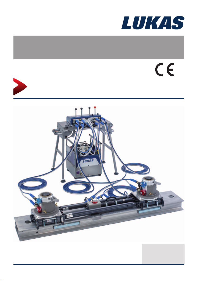
Instruction manual
Rerailing equipment
System overview
(Translation of the original instruction manual)
1490000085 EN
Edition 09.2014

2

Content Page
1. Danger classifi cations 4
2. Product safety 5
3. Proper use 8
4. System description 9
4.1 System and components 9
4.2 Example scenario 1 - Single point lifting 10
4.3 Structure and process - Single point lifting 11
4.4 Example scenario 2 - Two point lifting 16
4.5 Structure and process - Two point lifting 17
5. Notes 22
3
1. Danger classifi cations
We differentiate between various different categories of safety instructions. The table shown
below provides an overview of the assignment of symbols (pictograms) and signal words to
the specifi c danger and the possible consequences.
Pictogram
Damage /
injury to
Persons
Property
- NOTE
Key word Defi nition Consequences
DANGER! Immediate danger
WARNING!
CAUTION!
ATTENTION!
Potentially
dangerous
situation
Less dangerous
situation
Danger of damage
to property/
environment
Handling tips and
other important/
useful information
and advice
Death or severe
injury
Potential death or
serious injury
Minor or slight
injury
Damage to the
equipment,
damage to the
environment,
damage to
surroundings
No injury/damage
to persons/
environment/
device
Wear a helmet with a face guard
Wear protective gloves
Wear safety shoes
Proper recycling
Protect the environment
Read and follow the operating instructions
4
2. Product safety
LUKAS products are developed and manufactured to ensure the best performance and
quality when used as intended.
The safety of the operator is the most important consideration in product design. Furthermore,
the operating instructions are intended to help in using LUKAS products safely.
The generally applicable legal and other binding regulations pertaining to the prevention of
accidents and protection of the environment apply and are to be complied with in addition to
the operating instructions.
The equipment must only be operated by persons with appropriate training in the safety
aspects of such equipment – otherwise, there is a danger of injury.
We would like to point out to all users that they should read carefully the operating instructions
and the instructions contained therein before they use the equipment, and that they should
carefully follow such.
We further recommend you have a qualifi ed trainer show you how to use the product.
WARNING / CAUTION!
The operating instructions for the hoses, the accessories and the connected
devices must also be heeded!
Even if you have already received instruction on how to use the equipment, you should still
read through the following safety instructions again.
WARNING / CAUTION!
Ensure that the accessories and connected equipment are suitable for the
maximum operating pressure!
Please ensure that no body
parts or clothing get stuck
between the visibly moving
parts.
Wear protective clothing,
a safety helmet with visor,
protective footwear and gloves
Immediately report any
changes that occur (including
changes in operating
behaviour) to the appropriate
persons/departments! If
necessary, the equipment is to
be shut down immediately and
secured!
Working under suspended
loads is not permitted where
such loads are being lifted
only using hydraulic devices.
If working under suspended
loads is unavoidable, suitable
mechanical props are also
required.
Inspect the device before and
after use for visible defects or
damage.
Check all lines, hoses and
screwed connections for leaks
and externally visible damage,
and repair immediately!
Escaping hydraulic fl uid can
cause injuries and fi res.
5
In the event of malfunctions,
immediately deactivate the
equipment and secure it.
Repair the fault immediately.
Do not carry out any changes
(additions or conversions)
to the equipment without
obtaining the approval of
LUKAS beforehand.
Observe all safety and danger
information on the device and
in the operating instructions.
Any mode of operation which
compromises the safety and/
or stability of the device is
forbidden!
Safety devices must never be
disabled!
Make sure before switching
on/starting up the device and
during its operation, that this
will put no one in danger.
When working close to live
components and cables,
suitable measures must be
taken to avoid current transfers
or high-voltage transfers to the
equipment.
All safety and danger
information on the device must
always be complete and in a
legible condition.
Observe all intervals for
recurring tests and/or
inspections that are prescribed
or stated in the operating
instructions.
The maximum permitted
operating pressure noted on
the equipment must not be
exceeded.
Only genuine LUKAS
accessories and spare parts
are to be used for repairs.
Please ensure that, when
working with this equipment or
during transportation of such,
you don’t get caught up in the
looped hoses and trip.
The build-up of static charge
and therefore possible
sparking must be avoided
when handling the device.
6
The equipment is fi lled with
hydraulic fl uid. This hydraulic
fl uid can be detrimental to
health if it is swallowed or
its vapour is inhaled. Direct
contact with the skin must be
avoided for the same reason.
Also, when handling hydraulic
fl uid, note that it can negatively
affect biological systems.
When working with or storing
the equipment, ensure that the
function and the safety of the
equipment are not impaired
by the effects of severe
external temperatures or that
the equipment is damaged in
any way. Please note that the
equipment can also heat up
over a long period of use.
Make sure there is adequate
lighting while working.
Always keep these operating
instructions easily accessible
at the place of operation.
In addition to the safety instructions in this operating manual, all generally applicable,
statutory and otherwise binding national and international regulations for accident prevention
must be heeded and disseminated!
Before transporting the
equipment, always ensure that
the accessories are positioned
in such a way that they cannot
cause an accident.
Dispose properly of all
disassembled parts, oil and
left-over fl uid, as well as
packaging materials.
WARNING / CAUTION / ATTENTION!
The device is intended exclusively for the purpose stated in the operating instructions
(see chapter "Proper Use"). Any other use is not considered to be as intended. The
manufacturer/supplier is not liable for any damage resulting from use not as intended. The
user bears sole responsibility for such use.
Proper use includes observance of the operating instructions and compliance with the
inspection and maintenance conditions.
Never work in a fatigued or intoxicated state!
WARNING / CAUTION / ATTENTION!
If you do injure yourself on the hydraulic installation, however, clean the wound
immediately and consult a doctor for treatment!
If you get hydraulic fl uid in your eye, fl ush it out immediately several times with
clear, clean water and consult a doctor!
Also, if you swallow hydraulic fl uid you should consult a doctor!
7
3. Proper use
The LUKAS rerailing system, consisting of actuation, control, traversing and lifting
components, were developed specially for rerailing, erection and maintenance work on railbound vehicle. All or just individual components of the system are used depending on the
requirements.
The accessories necessary for each particular application must be used during each
deployment.
You can obtain accessories and replacement parts for the hydraulic power pack from your
authorised LUKAS dealer!
When carrying out any work, use the control tables described here and the connected hoses
and equipment to ensure that you yourself, the involved and uninvolved persons in the
proximity of the work and objects in closer proximity during the lifting and traversing process
are not endangered.
Notes concerning additional measures and the use of additional ancillary equipment and
tools for a derailing in the rail network:
All necessary measures concerning vehicle safety and the rerailing concept
are stipulated, in principle, by the vehicle manufacturer or operator.
Y ou must observe the permissible lifting stroke values and the lifting angles stipulated by the
manufacturer's data.
Once the specifi c securing safety measures have been completed, the manager of the
assisting train will stipulate which working steps and which products are to be used.
The selection of the lifting points, stipulated by the manufacturer, depends on their
accessibility and the associated headroom. In practice, we lift, pack up, move and put down
(often on alternate sides).
The "System Overview" operating instructions describes handling the components of the
LUKAS traversing system for rerailing technology. In addition, you must observe the operating instructions of the individual components, as listed under heading 4.1. All the warning
and safety instructions in these instructions must also be observed.
This system overview does not make any claims regarding completeness, all the possible
dangerous events and accident scenarios in the rail network. In your actions you should
act responsibly in the spirit of safety at work.
For the products, ancillaries and any other technical systems that are used in addition to
the components of the LUKAS rerailing technology, their manufacturers are responsible
and any operating instructions provided for them by third parties must also be observed.
WARNING / CAUTION / ATTENTION!
The safety instructions in this operating instruction manual concerning the site of
erection and type of erection must always be observed!
The LUKAS rerailing system is not explosion protected!
ATTENTION!
Watch out vigilantly for any leaks in order to avoid threats to the environment.
8

4. System description
4.1 System and components
The overall system description contains additional information and examples of application
that are not mentioned (or only mentioned in part) in the individual operating instructions of
the system components.
The LUKAS rerailing technology consists of the components:
- Drive unit
- Control table
- DUO traversing unit with rerailing bridge and rolling carriage
- Lifting cylinders with accessories
There is a separate operating instruction for each component in the above list, in addition to
this system description.
The system is modular and is scalable. Both individual components, for simple applications,
and all components in the system, for more complex applications can be used. The individual
components have been tested in combination with each other and are matched together.
We describe, below, the individual system components and two examples of scenarios with
the relevant system arrangement in each case.
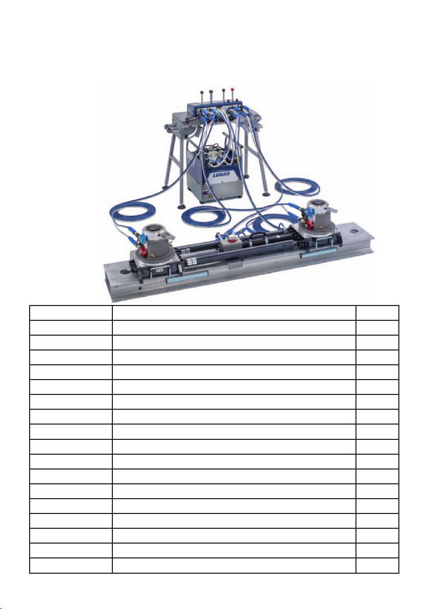
System overview:
(Example two point lifting)
Control table
Unit
Rolling
carriage
Lifting
cylinder
9
Rerailing bridge
DUO traversing unit
Adjustable connecting
rods

4.2 Example scenario 1 - Single point lifting
Single point lifting is carried out by the assisting train manager if rail-bound vehicles have
only been derailed slightly at the front and a suitable lifting point is available. The rear axle,
or the bogie, should still be on the rails to provide stability.
The assisting train manager assesses the damage situation and uses the equipment in
accordance with their intended use, or has them distributed.
Item No. Product Number
70-10-30 PC 650-2POWER electric motor 230V / 50 Hz 1
8411720043 10 litres hydraulic oil VG-10 2
70-63-01 Pair of hoses 10m control table-traversing cylinder 1
70-63-01 Pair of hoses 10m control table-locking pin 1
70-63-01 Pair of hoses 10 m control table-lifting cylinder 1
70-20-10 Control table CU 2DV, including support frame 1
840723765N Cylinder HP25/T 450R 1
841281319 Foot-plate Alu HP 10 / HP 25 1
840728863 Step set for HP 10/T...HP or 25/T... 1
70-30-10 Movement unit TC170/90-350, anchor hydraulic 1
840720640 Rolling carriage RC700/350 1
840726350 Rerailing bridge 1.1m x 140mm x 350mm 1
840725750 Rerailing bridge 2.2m x 140mm x 350mm 1
840726555 Connecting element 140mm 1
10

4.3 Structure and process - Single point lifting
All the hydraulic cylinders are ready for use as soon as they are unpacked.
That is to say, the equipment is fi lled with oil and has been bled of air.
All the hydraulic components supplied are accompanied by detailed individual operating
instructions, together with this system overview. The user must be familiar with them and
must observe them.
Drive
The drive unit is provided as hydraulic power packs with petrol engines (GC...) and electric
motors (PC...).
The petrol engine pump unit is supplied unfi lled, without engine oil, hydraulic oil and
fuel. Proceed as follows:
• Pour petrol into the petrol tank (see datasheet in separate operating instructions)
• Pour the engine oil supplied into the marked gearbox fi ller opening
• Pour hydraulic oil (hydraulic fl uid) into the power pack oil tank.
• Bleed the air from the power pack in accordance with the separate operating
Observe the oil fi ll level indicators (top sight glass must show oil half way up the window)
instructions
The electric motor pump unit is supplied unfi lled and without hydraulic fl uid. Depending
on the type, the hydraulic power packs with electric motors must be supplied with power at
the relevant voltage quoted in the technical data table (special voltages and frequencies on
request). Proceed as follows:
• Pour hydraulic oil into the power pack oil tank. Observe the oil fi ll level indicators
• PC 650-2POWER - 230 V / 50 Hz
• PC 650-4POWER - 400 V / 50 Hz
Both motor pump units can be connected hydraulically directly or via pairs of hose extensions. The units can be transported easily using the pull-out telescopic carrying handles.
(top sight glass must show oil half way up the window)
11

Hose lines with couplings
1.
2.
Only one type of hose is required for the various connection possibilities.
All connections are fi tted with nipples or sleeves to prevent mix-ups (can be coupled via
nipple and sleeve).
The hose lines are fi lled with hydraulic fl uid and bled of air in the as-delivered condition.
Proceed as follows to connect the hose ends:
1. The gold-coloured coupling nipple on the end of the hose must be connected fi rst.
Connection to the hydraulic cylinder is on the rod side, also called the annular chamber
side (= black coupling sleeve on blue connection block, see illustration).
2. The coupling sleeve of the hose is connected to the piston side of the cylinder (= silvercoloured coupling nipple on cylinder with red connection block) (see illustration).
1.
2.
The opposite hose end is directed to the control table and connected to a valve with the
symbol "Lift/Lower".
The locking mechanism of the coupling sleeve must always be actuated. This prevents
inadvertent separation of the hose lines if their couplings are pulled over an edge during
their routing, for example.
12

Control table
The CU 2DV control table is set up so that the vehicle to be lifted is in clear view.
The distance to the hydraulic cylinder furthest away should be such that the hose length
available has adequate reserve.
The scope of supply includes 1 m connection hose so that the hydraulic power pack can be
connected directly or at a distance using the pair of hose extensions.
The hose lines are coupled to the table in accordance with the symbols (see also Individual
Module - Control Table Operating Instructions).
Lifting cylinder with accessories
If the derailed rail-bound vehicle allows adequate space, the required rerailing equipment
can be introduced. With single-point lifting it is important to ensure that the hydraulic cylinder is correctly dimensioned with regard to its applied force and possible use of stacking
material.
If the necessary free space is not available around the derailed vehicle, foot-plates can
be used to carry out an initial lift. The foot-plate must be located fully on suitable stacking
material. The vehicle is also put down on the relevant lifting points using suitable stacking
material.
If the lift height is not adequate, a remedy can be achieved by using a step set.
LUKAS recommends that an inclination angle of 5° is not exceeded during lifting.
If stacking material is used between the cylinder or the roller carriage, it must be designed
for use with the relevant pressure and lateral forces . A stacking height appropriate to the
situation must also be taken into account.
13

Rerailing bridge
Various different bridge dimensions are available (see separate operating instructions for
LUKAS traversing system), depending on the requirement.
You need to take account of the permissible loading with respect to the support distance.
If parts of bridges need to be installed/connected, you need to provide packing under the
joint areas (see separate operating instructions for LUKAS traversing system).
The bridges must be set horizontally, even if the track is over height. The surface or running area of the bridge must be kept clean since otherwise smooth running of the roller carriage will be negatively affected.
The rail-bound vehicle describes an arc when rerailing.
For this reason, the bridge must be routed as precisely as possible in the direction of this
arc movement. Take account of the space requirement in the movement direction in order
to avoid having to relocate and avoid the associated complexity.
Rolling carriage
With single-sided movement of the rail-bound vehicle they describe a radius corresponding
to the length of the vehicle to be rerailed.
The rolling carriages are fi tted with removable Tefl on-coated slide plates.
These slide plates compensate this arc movement to a large extent if they are positioned
correctly.
The stop on the slide plate should be located on the outside of the arc in direction of travel
so that when the movement is to the inside, to the centre point of the arc, there is adequate
freedom for movement.
Rerailing bridge with rolling carriage
14

DUO traversing unit
The LUKAS traversing unit facilitates complete control of all the components from the control table.
The locking pin, also called the anchor cylinder, is a double-acting hydraulic cylinder that is
integrated in the DUO traversing unit to hold the position.
The hose line on the locking pin is coupled on the control table at the valve with the red
control lever and the relevant symbolic marking.
The traversing cylinder is connected in accordance with the description in the separate operating instructions for the LUKAS traversing system.
The stepwise setting down and moving in both directions can be carried out entirely from
the control table. The vehicle can thus be moved over extended distances in both directions directly from the control table.
The moving distance depends on the overall length of the rerailing bridge or the overall
length of the combined rerailing bridges.
DUO traversing unit connections at the control table
- red mark = connection at red control lever (control locking pin)
at control table;
- grey mark = connection at control lever next to the red control lever
locking/unlocking the traversing cylinder
(control traversing cylinder); traversing the traversing unit to the left or right
Locking pin
traversing
cylinder
15
4.4 Example scenario 2 - Two point lifting
Two point lifting is carried out by the assisting train manager if he considers the situation
of the rail-bound vehicle to be unstable, or if the rerailing concept provides for this. The assisting train manager assesses the damage situation and has the equipment and devices
positioned according to their intended purpose.
Item No. Product Number
70-10-30 PC 650-2POWER electric motor 230V / 50 Hz 1
8411720043 10 litres hydraulic oil VG-10 2
70-63-01 Pair of hoses 10 m control table-traversing cylinder 1
70-63-01 Pair of hoses 10 m control table-locking pin 1
70-63-01 Pair of hoses 10 m control table-lifting cylinder 2
70-20-10 Control table CU 2DV, including support frame 1
840724665N Cylinder HP10/T280R 2
840723765N Cylinder HP25/T 450R 2
84072466548 Piston plate for round piece r 40 mm 2
841281319 Foot-plate Alu HP 10 / HP 25 4
840728863 Step set for HP 10/T...HP or 25/T... 2
70-30-10 traversing unit TC170/90-350, anchor hydraulic 1
840720640 Rolling carriage RC700/350 2
LKHR840720571 Connecting rods1030-1800 1
LKHR840720575 Connecting rods1500-2800 1
840725750 Rerailing bridge 2.2m x 140mm x 350 mm 2
840726555 Connecting element 140mm 1
16
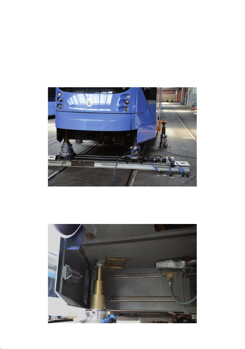
4.5 Structure and process - Two point lifting
The parts listed in the parts list (table) are matched to specifi c rail-bound vehicle with regard
to the dimensions and weight of the vehicle.
The vehicle is lifted up at the lifting points provided (see illustration below) in order to create
enough room for the traversing technology.
Suitable load carrying equipment can be used for this.
On the control table we connect two lifting cylinders HP25/T450 R to the left valve group.
Two lifting cylinders HP10/T280 R are connected to the right valve group.
Care must be taken to ensure that the specifi c left-hand cylinder is allocated to the left-
hand valve of the individual valve group. Connection on the right is carried out in an analogous manner.
This allows for better coordination of the control "Lift/Lower" and mix-ups are avoided.
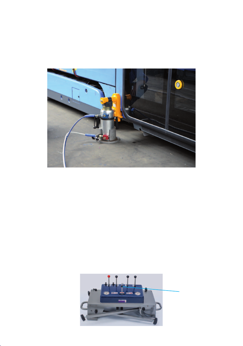
The preselection valve at the front of the control table must be set to the left (see illustration below). The vehicle can now be lifted or levelled up if it is at an angle.
The relevant cylinder extends or retracts by actuating the corresponding control lever.
Symbols on the control levers help the control and prevent incorrect lever actuation. When
the vehicle is horizontal, both vale levers are pulled at the same time. The vehicle is automatically lifted, synchronously and independently of the load distribution, until the desired
space is achieved or up to the permissible angle of inclination.
The pressure gauges each show the operating pressure on the left and right valve groups
on the control table. You can now apply the full traversing technology.
17
Control lever
preselection
valve
The rerailing bridge is placed under the derailed vehicle and is packed up with wooden
beams if necessary. If the length of a single bridge is inadequate, two bridges can be bolted together with the connecting element, thus providing an extension. Here again you need
to make sure that enough packing-up is provided.
Both rolling carriages are then placed on the bridges and connected together using the two
telescopic connecting rods. It makes sense to measure the centre distance between the
lifting points beforehand so that the connecting rods can be set accordingly.
Additional trapezoidal threads are provided on one side for fi ne adjustment.
The traversing cylinder can be arranged from the outside or between the two rolling carriages, depending on the space available.
Once the traversing technology has been introduced in accordance with the safety instructions, the preselection valve is moved to the right.
The load of the vehicle is transferred by extending the cylinders HP 10 / T280R.
18

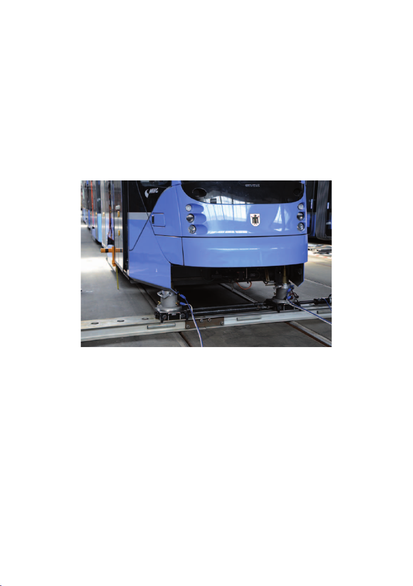
The preselection valve is now moved to the left again and the lifting cylinders HP 25/T450
R are fully retracted. To do this both the relevant control levers allocated to the cylinders
are pushed forwards at the same time.
The two lifting cylinders are then removed from the lifting points and the load is now resting
only on the traversing system (see example illustration below).
ATTENTION!
The operating pressure in the system must be dissipated before uncoupling
the hoses.
To do this, both the switching levers for pressure relief must be actuated and the control levers must be held in the end position in both directions "Extend/Retract" for three seconds
(see also control table operating instructions). When the pressure in the hoses is released
you will hear a hissing noise. The pressure in the hoses dissipates and the pressure gauges indicate 0 bar.
Both pairs of hoses are decoupled at the cylinders HP25/T450 R and connected to the
DUO traversing unit. The two switching levers for pressure release are moved to the start
position again.
The pair of hoses that is connected at the valve of the control lever with the red ball end ids
directed to the locking pin/anchor cylinder.
The other pair of hoses is coupled to the traversing cylinder (see illustration Page 15). Both
connections cannot be mixed up because only nipples can be connected to sleeves and
sleeves to nipples.
2 Switching lever
(Valves) for pressure
relief for trouble-free
hose exchange
Position I = pressure
Position O = nonpressure
ATTENTION!
Even after having
switched the pressure
relief valve to position
“O”, cylinders can move
in or out (lower/lift).
19
The holes in the rerailing bridge and the pins on the locking unit are manufactured as a
matched pair with regard to the angular inclination. This prevents the lock from coming
loose inadvertently.
If a single hole pitch is not adequate when traversing the bridge, the traversing cylinder
with the locking pin is moved by approx. 1 cm to the centre of the hole.
The locking pin is then released using the control lever with the red ball end.
The traversing cylinder can now be moved until the locking pin is located over the next hole.
LUKAS recommends traversing the pin outside the hole and then traversing it to the next
slotted hole in the extended condition, so that, in the event of an unexpected movement
(the vehicle tipping), the pin can engage automatically (for details see also the LUKAS traversing system operating instructions).
The extended locking pin in the slotted hole acts a holding or opposing bearing point.
If you have moved too far, by mistake, the traversing cylinder can be retracted without any
problems. The traversing cylinder can be moved in both directions from the control table.
The rail-bound vehicle is moved until the wheels are located precisely above the rail.
In the ideal case, the headroom would be adequate to place the rail-bound vehicle directly
on the track using the hydraulic cylinders HP 10/T280 R.
If this is not the case, the two lifting cylinders HP 25/T450 R are also used, as described
above, to lift the vehicle "externally" (not on the rerailing bridge).
The vehicle load is taken up at the two fi rst-mentioned lifting points.
After this, the two front cylinders can be retracted and the entire traversing technology can
be removed or moved to a different location.
Then the vehicle can be lowered using the cylinders HP25/T450 R and set on the track.
20

ATTENTION!
The operating pressure in the system must be dissipated before uncoupling
the hoses.
When the rerailing work is complete you must release the operating pressure
in the installation/system.
Before uncoupling all the hose line, the piston rods need to be retracted into the cylinders
and then extended by max. 5 mm.
Switch the hydraulic power pack motor off in this position and actuate all the control levers
in both directions.
You normally hear a pressure release sound (hissing). The pressure in the hose lines dissipates and the pressure gauges on the control table indicate 0 bar.
All the components can now be dismantled and stored away.
(Also observe the operating instructions for the individual components with regard to shutdown and storage).
Closing remark:
The example application above refers to a low-fl oor rail-bound vehicle 300-350 mm from
the top edge of the rail.
High-fl oor rail-bound vehicles 800-1000 mm from the top edge of the rail or with LOK and
goods traffi c have proven, in our experience, to offer more favourable installation conditions.
21

5. Notes
22

23
Please dispose of all packaging materials and
removed items properly.
LUKAS
A unit of the IDEX Corporation
Hydraulik GmbH
Weinstrasse 39, D-91058 Erlangen, Germany
Tel.: (+49) 0 91 31 / 698 - 0
Fax.: (+49) 0 91 31 / 698 - 394
e-mail: lukas.info@idexcorp.com
www.lukas.com
Made in GERMANY
© Copyright 2014 LUKAS Hydraulik GmbHRerailing_system_overview_manual_1400000085_en.indd
Subject to changes
 Loading...