

Page 1
Operating Instructions
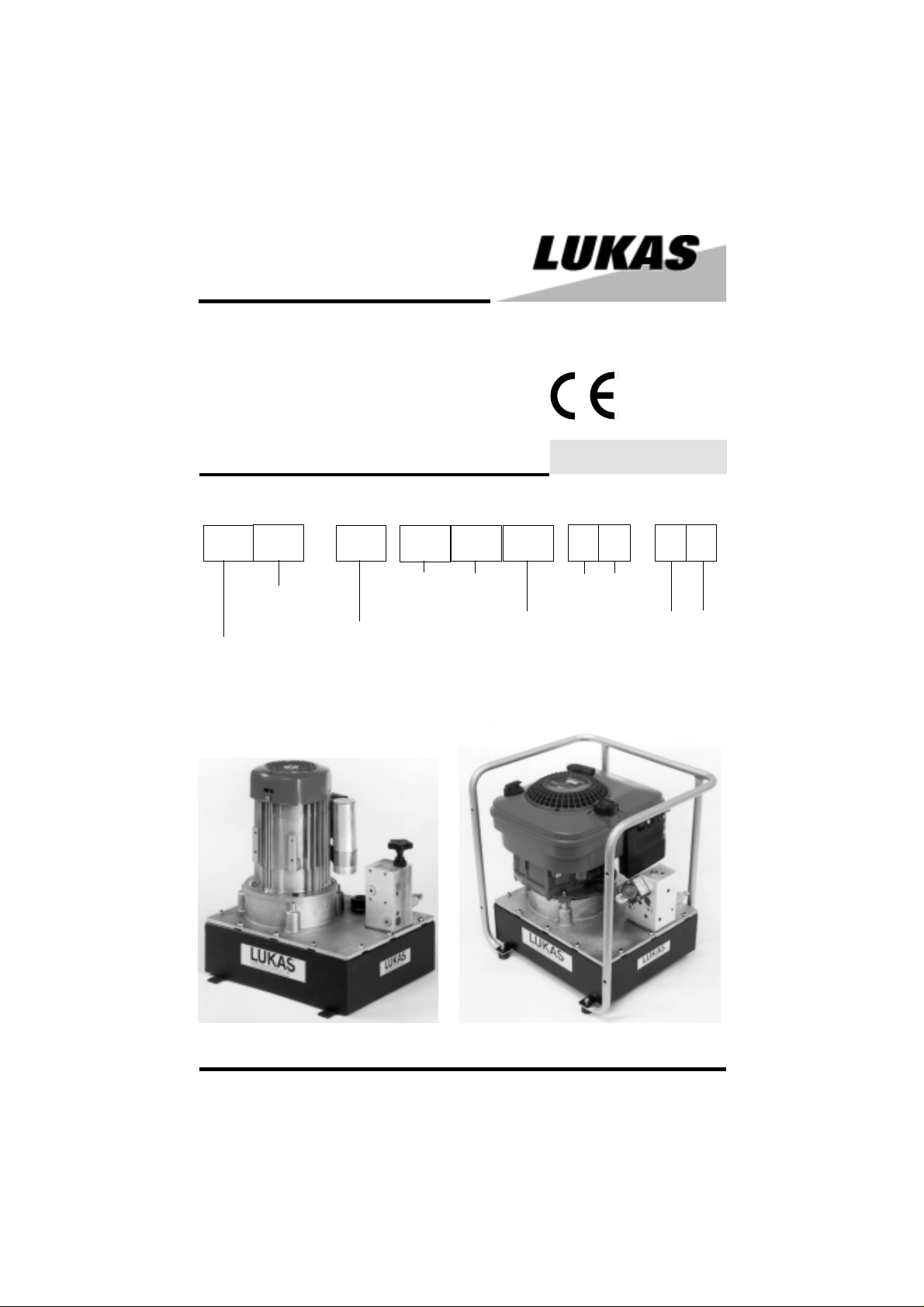
Hydraulic Tools
PO6 - Hydraulic Power Pack
84112/5601-85 GB
Issue 1.2005
replaces 5.98
PO GO 6 1E 2E 1D 10 25 50 70
= driven by 4stroke petrol
engine
= driven by
electric motor
Series
Operation of 1 resp. 2
single-acting cylinders
Operation of 1
double.acting cylinder
Nominal size of
oil container in l
Operating
pressure in
MPa
PO6 - 1E - 10
GO6 - 1D - 10 (with optional carry frame)
1
Page 2

1 Basic operation and designated use of the machine
1.1 The machine has been built in accordance with state-of-the-art standards and the recognized
safety rules. Nevertheless, its use may constitute a risk to life and limb of the user or of third parties,
or cause damage to the machine and to other material property.
1.2 The machine must only be used in technically perfect condition in accordance with its
designated use and the instructions set out in the operating manual, and only by safety-conscious
persons who are fully aware of the risks involved in operating the machine. Any functional disorders,
especially those affecting the safety of the machine/plant, should therefore be rectified immediately.
1.3 The machine is exclusively designed for the application mentioned in the operating instruc-
tions. Using the machine for purposes other than those mentioned above is considered contrary
to its designated use. The manufacturer/supplier cannot be held liable for any damage resulting
from such use. The risk of such misuse lies entirely with the user.
Operating the machine within the limits of its designated use also involves observing the
instructions set out in the operating manual and complying with the inspection and maintenance
directives.
2 Organizational measures
2.1 The operating instructions must always be at hand at the place of use of the machine.
2.2 In addition to the operating instructions, observe and instruct the user in all other generally
applicable legal and other mandatory regulations relevant to accident prevention and environmental protection.
This also applies for wearing protective clothing, helmet with visor or goggles and protective gloves.
2.3 In order to avoid injuries, the machine must only be operated by a specially trained operator
who has undergone a safety training.
2.4 Observe all safety instructions and warnings attached to the machine.
Make sure that safety instructions and warnings attached to the machine are always complete and
perfectly legible.
2.5 Never make any modifications, additions or conversions which might affect safety without the
supplier’s approval. This also applies to the installation and adjustment of safety devices and
valves.
2.6 Spare parts must comply with the technical requirements specified by the manufacturer.
Spare parts from original equipment manufacturers can be relied to do so. It is only allowed to use
original LUKAS spare parts or LUKAS system components.
2.7 Replace hydraulic hoses within stipulated and appropriate intervals even if no safety-relevant
defects have been detected. This has to be done after 10 years at the latest.
2.8 Adhere to prescribed intervals or those specified in the operating instructions for routine
checks and inspections.
2.9 Ensure that packing material and dismounted parts are disposed of properly!
2
Page 3

3 General safety instructions
3.1 In the event of malfunctions, stop the machine immediately and lock it. Have any defects
rectified immediately.
3.2 Before starting up or setting the machine in motion and during operation of the machine make
sure that nobody is at risk.
3.3 Before transporting the machine always check that the accessories have been safely stowed
away.
3.4 Make sure that there is enough lighting during work.
3.5 Avoid any operation that might be a risk to machine stability.
3.6 Check the machine at least after every operation for obvious damage and defects. Report any
changes (incl. changes in the machine’s working behaviour) to the competent organization/person
immediately. If necessary, stop the machine immediately and lock it. All lines, hoses and screwed
connections have to be checked for leaks and obvious damage. Repair damage immediately.
Splashed oil may cause injury and fire.
3.7 All safety equipment has to be checked for completeness and flawless condition:
- instruction markings and warning signs (safety instructions)
- check safety cover (e.g. motor-safety covers, heat protection etc.) if they are available and
if they are in good condition.
3.8 Working under loads is not allowed if they are only lifted by hydraulic cylinders. If the work is
indispensable sufficient mechanical supports are needed additionally.
3.9 Make sure that hoses are not mechanically stressed (pulling, bending etc.).
3.10 When working in the vicinity of live components and cables, suitable precautions must be
taken to avoid current conductions or high-voltage flashovers to the motor pump.
3.11 During use of the power package, the creation of electrostatic charges which could result in
sparking must be prevented.
3.12 The power package should always be placed in such a way that its function and safety will
not be impaired by strong external temperature influences.
4 Instructions for maintenance and service
4.1 For the execution of maintenance and service work, tools and workshop equipment adapted
to the task on hand are absolutely indispensable.
Work on the hydraulic system must be carried out only by personnel having special knowledge and
experience with hydraulic equipment.
4.2 Before putting into operation clean the machine, especially connections and threaded unions,
of any traces of oil, fuel or preservatives before carrying out maintenance/repair. Never use
aggressive detergents. Use lint-free cleaning rags and pay attention that the components are
meticulously clean during reassembling after repair.
4.3 During dismantling of machines it is necessary to collect the outrunning hydraulic liquids
completely, so that they cannot reach the ground. They have to be disposed properly according to
the instructions.
3
Page 4

4.4 Always tighten any screwed and thread connections that have been loosened during
maintenance and repair. Observe the stipulated torques.
4.5 Work on the electrical system or equipment may only be carried out by a skilled electrician
himself or by specially instructed personnel under the control and supervision of such electrician
and in accordance with the applicable electrical engineering rules.
4.6 The electrical equipment of machines is to be inspected and checked at regular intervals.
Defects such as loose connections or scorched cables must be rectified immediately.
4.7 Aggressive material (acid, lye, solvent, vapour) can damage the machine. It is necessary to
clean the whole machine if it must be exceptionally operated under such conditions or gets into
touch with these materials. Additionally, the machine must be checked as described under 3.6.
Device-specific information
Ensure the correct power supply acc. to the motor data on the nameplate.
If external devices with operating pressures < 50/70 MPa are connected, they may be damaged.
Used oil must be disposed of at a used oil disposal station to avoid environmental pollution.
Please refer to our separate booklet "Safety instructions for hydraulic hoses"
HR 84150/8056-85!
5 Intended use
LUKAS hydraulic power packs are exclusively designed for the operation of LUKAS hydraulic
cylinders. Hose nipples and hoses are not part of the power pack's scope of supply and can be
obtained from LUKAS.
6 Description
6.1 Drive system
6.1.1 The motor pump serves as hydraulic power supply. It includes a LUKAS radial piston
pump with:
- Low pressure circuit (up to 16 MPa) = LP. -
High pressure circuit (up to 50 resp. 70 MPa)= HP.
6.1.2 Following drive motors are available:
- electric motors single-phase AC with voltage 115V / 230 V
- 4-stroke combustion engine
6.1.3 Necessary valves are integrated in the pump unit:
- Switch-over from low to high pressure mode is made automatically by a pressure limiting
valve.
- The maximum working pressure is limited by a pressure relief valve set to 50 resp. 70 MPa.
6.1.4 Power packs with 10 l oil container
The oil container is filled ex works with 7.5 l of hydraulic oil. If necessary, the oil container can be
filled up to a total volume of 10l. The filler plug for hydraulic oil (fig. 1) includes a dipstick with 3 marks:
1 = min. oil level 5 l ; 2 = standard oil level 7.5 l ; 3 = max. oil level 9 l
4
Page 5

6.1.5 Power packs with 25 l oil container
The oil container is filled ex works with 15 l of hydraulic oil. If necessary,
the oil container can be filled up to a total volume of 24 l.
The filler plug for hydraulic oil (fig. 1) includes a dipstick with 2 marks:
1 = standard oil level 15 l ; 2 = max. oil level 24 l
6.2 Control valves
A number of control valve versions is available to meet different operator’s
requirements.
6.2.1 Drain valve "1E" for control of one single-acting jack
6.2.2 2-way distributor valve "2E" for control of two single-acting jacks
6.2.3 4/3-way valve "1D" for control of one double-acting jack
6.3 Hydraulic diagrams as per 6.2
Filler plug for
hydraulic oil
fig.1
7 General steps prior to lifting
7.1.1 Version "1E" : Open hand wheel (1) on the drain valve (see fig. 2).
7.1.2 Version "2E" : Open hand wheel (1) on the drain valve. Close hand wheels (3) on the
7.1.3 Version "1D" : Switch hand lever on the control valve to middle position (= marked O)
7.1.4 Starting the motor
----> Petrol engine: see separate operating manual.
Open the petrol cock and start the motor.
----> Electric motor: The on/off switch of the motor is situated at the motor terminal box.
Position I: the motor is started.
Position 0: motor standstill.
2-way distributor valve (see fig. 3).
(see fig. 4).
5
Page 6

8 Lifting with single-acting jacks
8.1 Power pack type PO6 - 1E and GO6 - 1E
8.1.1 Connection
Remove the screw plug at connection A of the valve block and screw in hose
connection nipple. Connect pipe or hose to cylinder.
Connection "T" stays locked.
8.1.2 Operation (see fig. 2)
Start the motor and close drain valve (turn hand wheel 1 to the right to fully
closed position) so the jack extends with the motor running. The load holding function can be
obtained by switching the motor off. The piston can be retracted (by spring pressure) by opening
the drain valve (turn hand wheel 1 to the left).
fig. 2
8.2 Power pack Typ PO6 - 2E and GO6 - 2E
Remove the screw plug at connection A/B of the valve block and screw in hose connection nipple.
Connect pipe or hose to cylinder.
Connection "T" stays locked.
8.2.1 Extension of the cylinder (see fig. 3)
- prior to starting the motor the hand wheels (3) on the 2-way distributor
valve must be closed (turn them to the right)
- start the motor,
- open both hand wheels slowly and simultaneously,
- synchronize the extension speed of both cylinders by further opening
or partly closing the hand wheels.
8.2.2 Load holding function
With version 2E a reliable load holding function can be obtained only when
both hand wheels (3) on the 2-way distributor valve are fully closed.
By no means the motor is allowed to be switched off with the hand wheels open as long as
a load is resting on the cylinders!
8.2.3 Retraction of the cylinders
- hand wheels (3) on the 2-way distributor valve are closed,
- open hand wheel (1) on the drain valve (turn it to the left),
- slowly open hand wheels (3) on the 2-way distributor valve,
- control the retraction speed of both cylinders by further opening resp. partly closing the
hand wheels.
fig. 3
9 Lifting with double-acting jacks
9.1 Power pack Typ PO6-1D and GO6-1D
9.1.1 Connection
Remove screw plug at connections A and B of the valve block and screw in hose connection nipple.
Connect pipe or hose to cylinder.
Connection: "A" to piston side, "B" to piston rod side
6
Page 7

9.1.2 Operation
Each cylinder movement can be controlled by the 4/3-way valve.
Position I (A) Extended position.
Position 0 (Centre position of the oper. lever)
Position II (B) The cylinder is hydraulically retracted.
Load holding function with oil flow from P ---> T.
The valve can be switched from the extended or the retracted position into
the neutral position without pressure losses in the cylinder
(positive overlap in the valve).
fig. 4
10 Preparations and Putting into Operation
10.1 General
Unpack the hydraulic pump, check the completeness of the delivery.
The hydraulic power packs are delivered with oil filling (LUKAS-oil HLP 10).
10.2 Venting of power pack during operation
- For refilling and new filling of the oil tank, remove the oil filler screw on the tank cover and fill
in the hydraulic oil.
- Prior to first putting into operation and after repair works the hydraulic system must be vented
(see item 10.3).
10.3 Venting of power pack
10.3.1 Type -1E/
Close connection A (fig. 1). Open drain valve (fig. 2).
10.3.2 Type -2E
Close hand wheels item 3 (fig. 3) by turning them to the right and open drain valve item 1 (fig. 3).
10.3.3 Type 1D
Close pressure connections A + B (fig. 1).
Switch valve in centre position 0 (fig. 3).
10.3.4 Venting
Start the motor approx. 10 times for a short time and switch it off again, so that the motor only runs
at low speed. The motor must be brought to a standstill before restarting.
11 Options
The equipment described below is not part of the standard scope of supply, but special equipment
which is to be purchased separately.
11.1 Pressure gauges
11.1.1 for type -1E/ -2E MEL 500 MEL 700
Insert the pressure gauge adapter directly into the connection bore A. resp. B. (see fig. 2 and 3)
11.1.2 for type -1D MEG 500 MEG 700
- Remove screw plug G 1/4" in connection M situated on top of the valve block (see fig. 4)
- Screw in the pressure gauge with the stem.
7
Page 8

11.2 Carry frame
To facilitate their transport, the power packs can be upgraded with a carry frame which must be
ordered separately as a mounting kit.
Ref. no. for power packs with 10l - tank V84150/7601-03.
Ref. no. for power packs with 25l - tank - upon request.
11.3 Quick-connect couplings
All power packs can be equipped with quick-connect couplings. Your LUKAS leader will be glad to
offer you the couplings that you need.
12 Maintenance
12.1 Oil level/Oil change
- Check the hydraulic oil level after each operation and fill in new oil, if necessary.
- Check the hydraulic power pack for possible leakages.
- The cylinder must be retracted for filling in oil.
The desired oil level can be checked with the dipstick. (see 6.1.4 resp. 6.1.5)
The oil change should be made after approx. 100 operating hours. The cork gasket and the sealing
ring on the oil drain plug must be replaced with each oil change. The intervals between further oil
changes depend on the operating hours and the pollution of the oil.
12.2 Oil for LUKAS hydraulic tools mineral oil DIN 51524 and others
Oil temperature range Viscosity rating Comments
A - 24 ... + 30 °C HL 5
B - 18 ... + 50 °C HLP 10
C - 8 ... + 75 °C HLP 22
D + 5 ... + 80 °C HLP 32
E - 8 ... + 70 °C HF - E 15 Biodegradable
recommended range of viscosity : 10...200 (mm2/s).
12.3 Preventive Maintenance
The oil tank must principally be cleaned with each oil change. To clean the oil tank, the mounting
nuts on the oil tank cover must be loosened and the motor/pump unit pulled out.
Attention: Do not use textiles!
The tank must be cleaned by flushing with hydraulic oil.
13 Service
Service may be carried out exclusively by the manufacturer of the device or by personnel trained
by the manufacturer and the authorized dealer.
Only genuine LUKAS spare parts may be used for repair works.
When carrying out maintenance or service works be sure to wear protective clothing (see safety
regulations), since hydraulic devices may be under pressure even in unoperated state.
8
Page 9

14 Technical data
Type Ref. no. Type Ref. no. Oil capacity Usable oil cap.
500 bar 84112/ 700 bar 84112/ standard-max. standard-max. ca. kg
PO6-1E-10-50 5607 5601 7.5 l 6 l Electric motor 34
PO6-2E-10-50 5608 5602 -- -- 230 V/50 Hz, 1,5 kW 36.5
PO6-1D-10-50 5609 5603 9 l 7.5 l electr. protection acc. 35
PO6-2E-25-50 5628 5622
PO6-1D-25-50 5629
GO6-1E-10-50 5610 5604 7.5 l 6 l
GO6-2E-10-50 5611 5605 -- -GO6-1D-10-50 5612 5606 9 l 7.5 l
GO6-2E-25-50 5631 5625
GO6-1D-25-50 5632 5626 36.5
-..-70
5623 IP 54 41.5
15 l - 24 l 10 l - 19 l
15 l - 24 l 10 l - 19 l 3200 min
Motor
to DIN EN 60034-5 43
4-stroke gasoline
engine
2.6 kW
Weight*
33,5
-1
* Weight without oil filling
14.1 Delivery
epyT
-..Pnim/l4,4nim/l4,1
-..Gnim/l7,4nim/l54,1
yrevileD
erusserpwolerusserphgih
revohctiws
erusserp
aPM61
14.2 Noise emission
following the regulations horizontal measuring distance 1,0 [m] 5,0 [m]
of EN ISO 3744: measuring distance above the
upper edge of the power pack 1,0 [m] 1,0 [m]
82 dB(A) 72 dB(A)
31
32
38
14.3 Others
Temperature range:
Ambient temperature (power pack in operation) -24 ... +45 [°C]
Storage temperature (power pack not in operation) -30 ... +60 [°C]
15 Trouble Shooting
Malfunction No delivery or only partial delivery from pump at no load.
Cause Air in the suction area of the pump.
Remedy Reduce the pressure at no load as far as possible - turn the adjusting screw of
the pressure limiting valve in anti-clockwise direction. Switchíng the pump on/off
repeatedly supports the venting process.
9
Page 10

LUKAS Hydraulik GmbH
A Unit of IDEX Corporation
Weinstraße 39, 91058 Erlangen, Germany
Postfach 2560, 91013 Erlangen, Germany
Telefon (09131) 698-0 • Telefax (09131) 698-394
E-Mail: info@lukas.de
84112_5601_Ag105_e.P65 Subject to revision
10
© Copyright 1998 LUKAS Hydraulik GmbH
 Loading...