

Operating Instructions
Hydraulic Tools
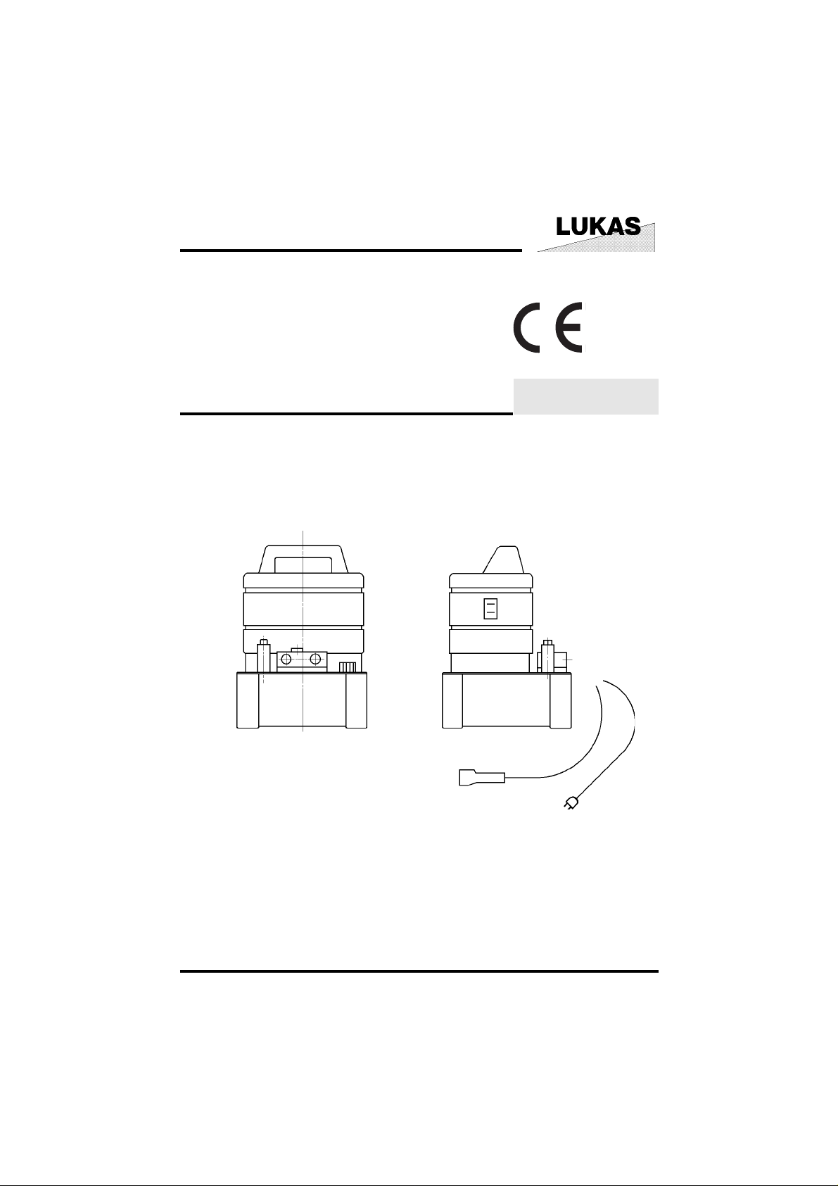
Hydraulic Power Packs PO-4
84112/0120- 85 GB
Issue 3.98
replaces 11.94
PO_A1_1.TIF
1

1 Basic operation and designated use of the machine
1.1 The machine has been built in accordance with state-of-the-art standards and the recognized
safety rules. Nevertheless, its use may constitute a risk to life and limb of the user or of third parties,
or cause damage to the machine and to other material property.
1.2 The machine must only be used in technically perfect condition in accordance with its
designated use and the instructions set out in the operating manual, and only by safety-conscious
persons who are fully aware of the risks involved in operating the machine. Any functional disorders,
especially those affecting the safety of the machine/plant, should therefore be rectified immediately.
1.3 The machine is exclusively designed for the use described in the operating manual. Using
the machine for purposes other than those mentioned in the manual, such as driving and controlling
other pneumatic systems, is considered contrary to its designated use. The manufacturer/
supplier cannot be held liable for any damage resulting from such use. The risk of such misuse lies
entirely with the user.
Operating the machine within the limits of its designated use also involves observing the
instructions set out in the operating manual and complying with the inspection and maintenance
directives.
2 Organizational measures
2.1 The operating instructions must always be at hand at the place of use of the machine.
2.2 In addition to the operating instructions, observe and instruct the user in all other generally
applicable legal and other mandatory regulations relevant to accident prevention and environmental protection.
This also applies for wearing protective clothing, helmet with visor or goggles and protective gloves.
2.3 In order to avoid injuries, the machine must only be operated by a specially trained operator
who has undergone a safety training.
2.4 Observe all safety instructions and warnings attached to the machine. Make sure that safety
instructions and warnings attached to the machine are always complete and perfectly legible.
2.5 Never make any modifications, additions or conversions which might affect safety without the
supplier’s approval. This also applies to the installation and adjustment of safety devices and
valves.
2.6 Spare parts must comply with the technical requirements specified by the manufacturer.
Spare parts from original equipment manufacturers can be relied to do so. It is only allowed to
use original LUKAS spare parts or LUKAS system components.
2.7 Replace hydraulic hoses within stipulated and appropriate intervals even if no safety-relevant
defects have been detected. This has to be done after 10 years at the latest.
2.8 Adhere to prescribed intervals or those specified in the operating instructions for routine
checks and inspections.
2.9 Make sure to dispose properly of packing material and dismounted parts!
3 General safety instructions
3.1 In the event of malfunctions, stop the machine immediately and lock it! Have any defects
rectified immediately.
2

3.2 Before starting up or setting the machine in motion and during operation of the machine make
sure that nobody is at risk.
3.3 Before transporting the machine always check that the accessories have been safely stowed
away.
3.4 Make sure that there is enough lighting during work.
3.5 Avoid any operation that might be a risk to machine stability.
3.6 Check the machine at least after every operation for obvious damage and defects. Report any
changes (incl. changes in the machine’s working behaviour) to the competent organization/person
immediately. If necessary, stop the machine immediately and lock it. All lines, hoses and screwed
connections have to be checked for leaks and obvious damage. Repair damage immediately.
Splashed oil may cause injury and fire.
3.7 All safety equipment has to be checked for completeness and flawless condition:
- instruction markings and warning signs (safety instructions)
- check safety cover (e.g. motor-safety covers, heat protection etc.) if they are available and if they
are in good condition.
3.8 Working under loads is not allowed if they are only lifted by hydraulic cylinders. If the work
is indispensable sufficient mechanical supports are needed additionally.
3.9 Make sure that hoses are not mechanically stressed (pulling, bending etc.).
4 Instructions for maintenance and service
4.1 For the execution of maintenance and service work, tools and workshop equipment adapted
to the task on hand are absolutely indispensable. Work on the hydraulic system must be carried
out only by personnel having special knowledge and experience with hydraulic equipment!
4.2 Before putting into operation clean the machine, especially connections and threaded unions,
of any traces of oil, fuel or preservatives before carrying out maintenance/repair. Never use
aggressive detergents. Use lint-free cleaning rags and pay attention that the components are
meticulously clean during reassembling after repair!
4.3 During dismantling of machines it is necessary to collect the outrunning hydraulic liquids
completely, so that they cannot reach the ground. They have to be disposed properly according to
the instructions!
4.4 Always tighten any screwed and thread connections that have been loosened during
maintenance and repair. Observe the stipulated torques!
4.5 Work on the electrical system or equipment may only be carried out by a skilled electrician
himself or by specially instructed personnel under the control and supervision of such electrician
and in accordance with the applicable electrical engineering rules.
4.6 The electrical equipment of machines is to be inspected and checked at regular intervals.
Defects such as loose connections or scorched cables must be rectified immediately.
4.7 Aggressive material (acid, lye, solvent, vapour) can damage the machine. It is necessary to
clean the whole machine if it must be exceptionally operated under such conditions or gets into
touch with these materials. Additionally, the machine must be checked as described under 3.6.
3

5 Safety instructions for hydraulic hoses
All instructions to safe use of hydraulic hoses can be found in the booklet HR 1495 35 219 delivered
with the hoses.
Device-specific information
Ensure the correct power supply acc. to the motor data on the nameplate. If external devices with
operating pressures < 50/70 MPa (500/700 bar) are connected, they may be damaged.
Used oil must be disposed of at a used oil disposal station to avoid environmental pollution.
6 Applications
LUKAS hydraulic power packs are exclusively designed for the operation of LUKAS hydraulic
cylinders.
Function diagram
FIG7.TIF
Type PO4-4-NA
FIG6.TIF
Type PO4-4-N3 Type PO4-4-N4
6.1 Single-acting cylinders
6.1.1 Power pack type PO4-4-NA-500 and PO4-4-NA-700
Type NA is equipped with a 2/2-way valve and can be used with
single-acting cylinders (see function diagram).
6.1.1.1 Operation (see fig. 1)
If the 2/2-way valve is closed (valve grip in position I), the cylinder
can extend with the pump switched on.
The pressure maintaining function is achieved by switching off
the motor.
If the valve is opened (valve grip in position II) the piston side is
connected with the oil tank and the cylinder can retract by means
of a return spring.
6.1.1.2 Connection
Screw hose nipple into connection A (10) at drain valve (12) (see fig. 10).
Remark
Hose nipples and hoses are not part of the power pack's scope of supply and can be obtained from
LUKAS.
4
fig. 1
PONA4.Tif
FIG8.TIF

6.1.2 Power pack type PO4-4-N3-500 and PO4-4-N3-700 (see function diagram)
The version N3 includes a 3/3-way valve.
6.1.2.1 Operation (see fig. 2)
In position I (A) the cylinder extends when the pump is
switched on.
In position 0 (centre position of the operating lever) pressure
maintaining function at oil flow from P ---> T.
In position II the piston side of the cylinder is connected to
the oil tank and the cylinder is retracted by means of a return
spring.
Remark
The power pack has the same function as under 6.1.1.1
except that valve position 0 enables the pressure maintaining
fig. 2
PON4.Tif
function also when the motor is running.
6.1.2.2 Connection
Remove the locking cap at connection A of the valve block (13) and screw in hose connection
nipple. Connect pipe or hose to cylinder (see fig. 10).
Remark
Hose nipples and hoses are not part of the power pack's scope of supply and can be obtained from
LUKAS.
6.2 Double-acting cylinders (see function diagram)
6.2.1 Power pack type PO4-4-N4-500 and PO4-4-N4-700
6.2.1.1 Operation (see fig. 2).
Type N4 is equipped with a 4/3-way control valve allowing
the control of double-acting cylinders.
The valve can be switched from the extended or the
retracted position into the neutral position without pressure
losses in the cylinder (positive overlap in the valve).
Each cylinder movement can be controlled by the 4/3-way
valve.
Position I (A) Extended position.
Position 0 (Centre position of the oper. lever).
Press. maintain. function at oil flow from P-->T.
Position II (B) The cylinder is hydraulically retracted.
fig. 2
PON4.Tif
6.2.1.2 Connection
Remove the locking cap in A and B of the valve block (13) and screw in hose connection nipple.
Connect pipe or hose to cylinder (see fig. 10).
Remark
Hose nipples and hoses are not part of the power pack's scope of supply and can be obtained from
LUKAS.
5

6.3 Electric control
The 3-step switch is located on the side of the plastic housing.
- Top position - position I the motor is started.
- Centre position - position 0 motor standstill.
- Bottom position - position II the electronic equipment is started, the motor, however, is not
switched on, but will be started via the remote control.
6.4 Thermostat
The power pack is equipped with a thermostat, which protects the motor against too high
temperatures by switching it off to avoid damages. After a cooling down phase, the motor is
automatically restarted.
7 Preparations and Putting into Operation
7.1 General
Unpack the hydraulic pump, check the completeness of the delivery.
The hydraulic power packs are delivered with oil filling (LUKAS-oil HLP 10).
7.2 Venting of power pack during operation
Before commissioning the power pack the oil filler and venting screw has to be opened by 2 to 3
turns for venting the oil container.
For refilling and new filling of the oil tank, remove the oil filler screw on the tank cover and fill in the
hydraulic oil.
Prior to first putting into operation and after repair works the hydraulic system must be vented (see
item 7.3).
For transporting close venting screw.
7.3 Venting of power pack
7.3.1 Type NA
Close connection A (item 10 fig. 10). Open drain valve (see fig. 1).
7.3.2 Type N3/N4
Close pressure connections A and B (see fig. 10).
Valve in centre position 0 (see fig. 2).
7.3.3 General
Start the motor approx. 10 times for a short time and switch it off again, so that the motor only runs
at low speed. The motor must be brought to a standstill before restarting.
6

8 Option
The equipment described below is not part of the standard scope of supply, but special equipment
which is to be purchased separately.
8.1 Pressure gauges (item. 11 fig. 10)
8.1.1 For type PO4-NA MEG 500
Remove screw plug G 1/4 in connection P above the connection board.
Screw in the pressure gauge with the stem.
8.1.2 For type PO4-N3 / PO4-N4
Insert the pressure gauge adapter directly into the connection bore A.
MEG 700
MEL 500
MEL 700
8.2 Remote control
The power pack with remote control is switched on by means of a pushbutton on the remote control
casing. The remote control is only put into operation when the 3-step switch (fig. 10, item 6) is set
to switch position II.
If you release the pushbutton the motor is stopped - inching mode -.
9 Maintenance
9.1 Oil level / Oil change
Check the hydraulic oil level after each operation and fill in new oil, if necessary.
Check the hydraulic power pack for possible leakages.
The cylinder must be retracted for filling in oil.
The oil level is correct, if the oil face is approx. 1 cm below the filling hole.
The 1st oil change should be made after approx. 100 operating hours. The cord packing Ø 6 mm
must be replaced with each oil change. The intervals between the further oil changes depend on
the operating hours and the pollution of the oil.
9.2 Oil for LUKAS hydraulic tools mineral oil DIN 51524 and others
Range of oil temperature Viscosity rating Remarks
A -24 ... +30°C HL 5
B -18 ... +50°C HLP 10
C -8 ... +75°C HLP 22
D +5 ... +80°C HLP 32
E -8 ... +70°C HF-E 15 biodegradable
recommended range of viscosity : 10...200 (mm2/s).
7

9.3 Preventive Maintenance
The oil tank must principally be cleaned with each oil change.
To clean the oil tank, the mounting screws on the oil tank cover must be loosened and the motor/
pump unit pulled out.
Attention
The tank must be cleaned by flushing with hydraulic oil.
Do not use textiles!
10 Service
Service may be carried out exclusively by the manufacturer of the device or by personnel trained
by the manufacturer and the authorized dealer.
Only genuine LUKAS spare parts may be used for repair works.
When carrying out maintenance or service works be sure to wear protective clothing (see safety
regulations), since rescue devices may be under pressure even in unoperated state.
10.1 Trouble Shooting
Malfunction
No delivery or only partial delivery from pump at no load.
Cause
Air in the suction area of the pump.
Remedy
Reduce the pressure at no load as far as possible - turn the adjusting screw of the pressure limiting
valve in anti-clockwise direction. Switchíng the pump on/off repeatedly supports the venting
process.
If the defects cannot be repaired, contact an authorized LUKAS dealer or the LUKAS service
department. The address: LUKAS Hydraulik GmbH, Weinstraße 39, 91058 Erlangen; P.O.B.
2560, 91013 Erlangen Germany; Service-Tel.: +49 / 91 31 / 6 98 - 3 38;
Fax: +49 / 91 31 / 69 83 53.
11 Technical data
Description Ref. no. Operating press. Dimensions Weight Remarks
PO4-4-NA 500 84112/12 50 22 for
PO4-4-NA 700 84112/22 70 22 singlePO4-4-NA 500F 84112/14 50 22,5 acting
PO4-4-NA 700F 84112/24 70 260x250x400 22,5 cylinders
PO4-4-N3/N4 500 84112/13 50 22,2 for
PO4-4-N3/N4 700 84112/23 70 22,2 doublePO4-4-N3/N4 500F 84112/15 50 22,7 acting
PO4-4-N3/N4 700F 84112/25 70 22,7 cylinders
weight including oil filling.
PN (MPa) (lxwxh) mm kg
8

rpm Voltage Power Oil delivery Oil capacity connection
3000 230V/50Hz 1~ 0,55 ND 2,1; HD 0,24 ca. 5 l G 1/4
Nominal size = 3000 rpm;
ND = low pressure 8 MPa (80 bar); HD = high pressure 50/70 MPa (500/700 bar);
Volumetric efficiency: > = 80%;
Oil specifications: delivered with mineral oil HLP 10/DIN 51524.
(kW) (l/min) Usable oil capacity thread
ca. 4 l
11.1 Noise emission: 84 dB(A)
following the regulations of horizontal measuring distance 1.0 [m],
DIN 45635 part 41: measuring distance above the upper
edge of the power pack 1.0 [m].
11.2 Others
Temperature range:
Ambient temperature (power pack in operation) -24..+45 [°C],
Storage temperature (power pack not in operation) -30..+60 [°C].
9

Motor pump components
POA1_.TIF
fig. 10
1 Motor unit with plastic hood 8 Remote control
2 Plastic oil tank 10 Connection taphole G 1/4
3 Pressure limiting valve 11 Thread G 1/4 for pressure gauge
4 Oil filler and venting screw 12 Connection board type NA - with
with gauge stick integrated 2/2-way valve
5 Carrying handle 13 Connection board type N3/N4
6 3-step switch 14 4/3 or 3/3-way valve
7 Power cable
POA1_1.TIF
LUKAS Hydraulik GmbH
A Unit of IDEX Corporation
Weinstraße 39, 91058 Erlangen
Postfach 2560, 91013 Erlangen • Germany
Tel.: +49 (0) 91 31/6 98-0 • Fax: +49 (0) 91 31/69 83 94
e-mail: info@lukas.de
PO4_e.P65 Subject to revision
10
© Copyright 1998 LUKAS Hydraulik GmbH
 Loading...