

Page 1
Instruction manual
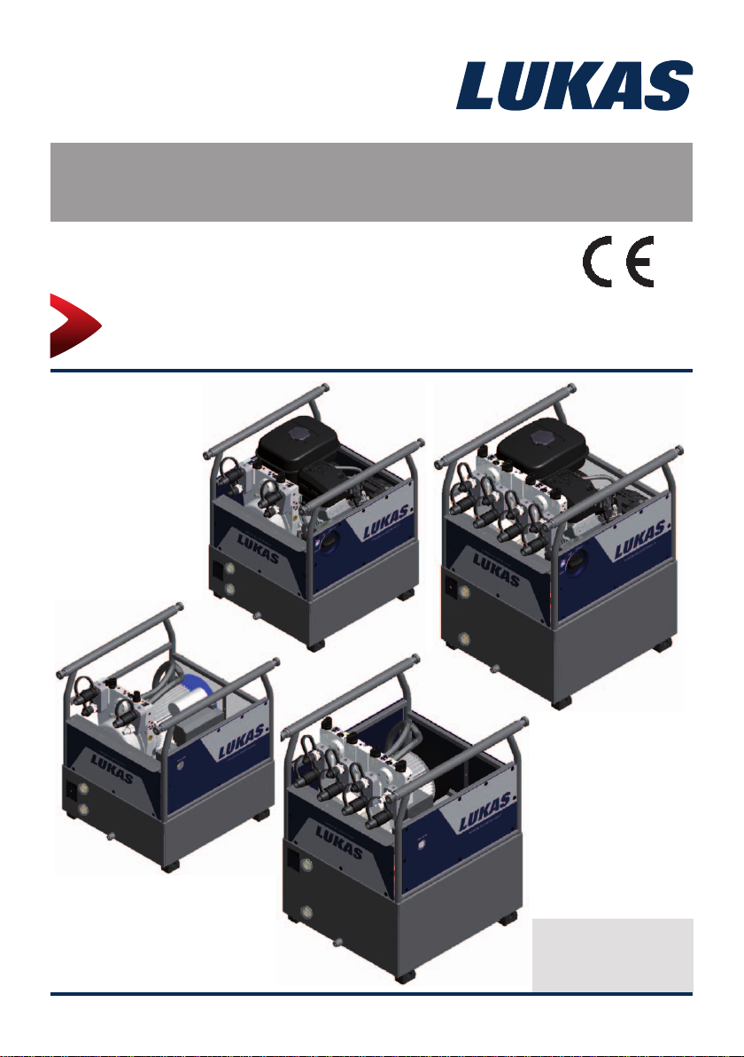
Rerailing equipment
Hydraulic power units GC/PC 650
GC 650
PC 650
1450000085 EN
Edition 08.2014
(Translation of the original instruction manual)
Page 2

Content Page
1. Danger classifi cations 5
2. Product safety 6
3. Proper use 10
4. Assembly marking 1 1
5. Functional description 11
5.1 General information 11
5.2 Layout of the units 12
5.3 Motor variants 13
5.4 Valve variants 14
5.5 Pumps 15
5.6 Frame with side sections 15
5.7 Connection to the control table 15
6. Connecting the hoses / devices 16
7. Erection and start-up 17
7.1 Set-up 17
7.2 Start-up 17
8.1 Starting the engines 18
8. Operation 18
8.2 Stopping the engine 19
8.3 Topping up with fuel (only on combustion engines) 20
8.4 Controlling the valves 20
9. Dismantling the equipment / deactivation following operation 22
10. Tests 23
10.1 Recommended test intervals 23
10.2 Hydraulic units with combustion engine 24
10.3 Hydraulic units with electric motor 25
10.4 Hoses (optional pairs of hose extensions) 25
11.1 General information 26
11. Maintenance and repair 26
11.2 Service work on the hydraulic unit 27
11.3 Additional service work on unit with combustion engine 29
11.4 Couplings 33
2
Page 3

Content Page
12. Troubleshooting 34
13. Technical data 40
13.1
13.2 GC 650-4POWER 42
13.3 GC 650E-2POWER 43
13.4 GC 650E-4POWER 44
13.5 PC 650-2POWER 45
13.6 PC 650-4POWER 46
13.7 Noise emissions of the power units 47
13.8 Sparking plug 47
13.9 Sparking plug spanner 47
13.10 Fuel 47
13.11 Engine oil 48
13.12 Hydraulic fl uid recommendation 48
13.13 Operating and storage temperature range 48
14. EC Declarations of conformity 49
15. Notes 50
GC 650-2POWER 41
3
Page 4

4
Page 5
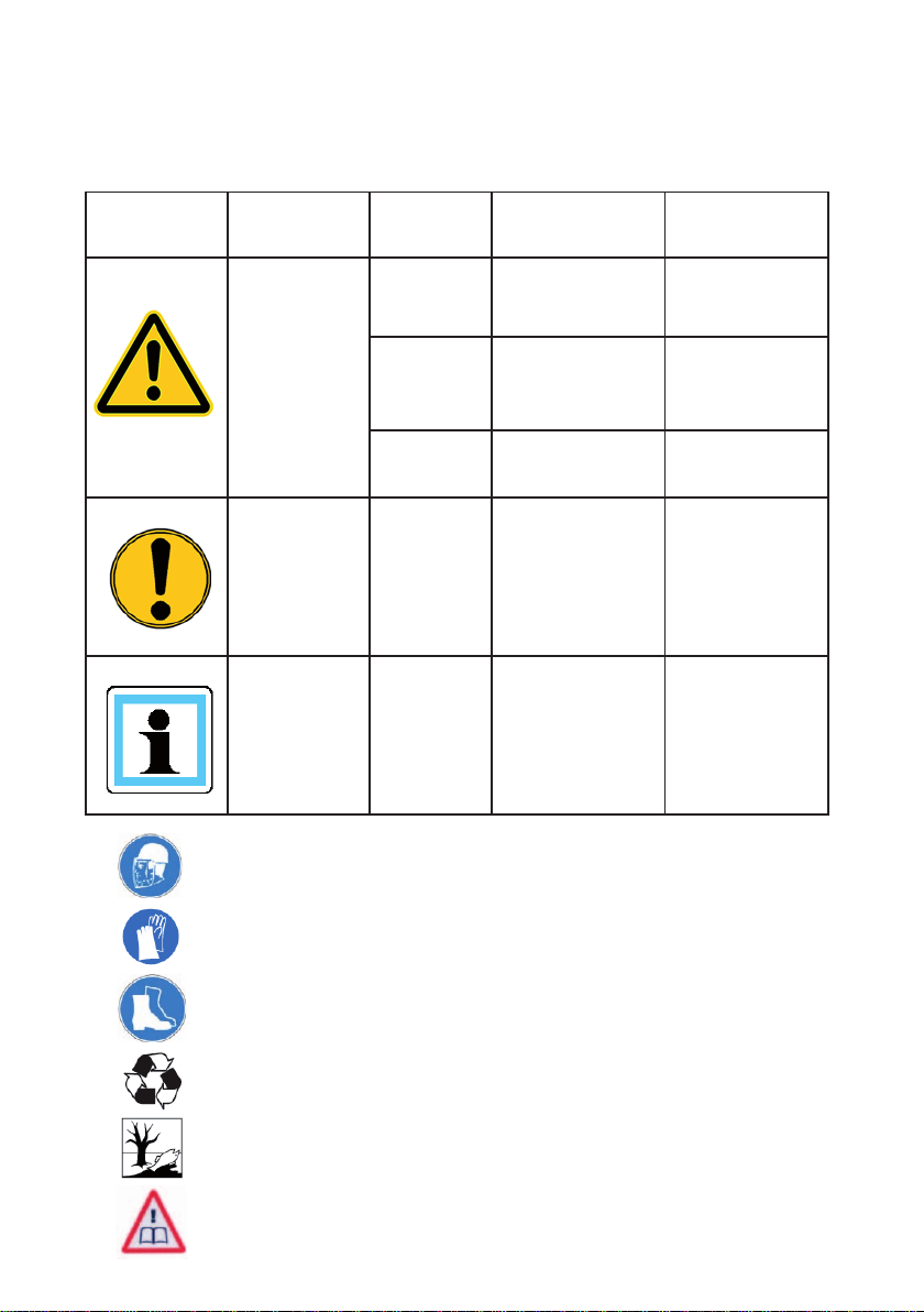
1. Danger classifi cations
We differentiate between various different categories of safety instructions. The table shown
below provides an overview of the assignment of symbols (pictograms) and signal words to
the specifi c danger and the possible consequences.
Pictogram
Damage /
injury to
Persons
Property
- NOTE
Key word Defi nition Consequences
DANGER! Immediate danger
Potentially
WARNING!
CAUTION!
ATTENTION!
dangerous
situation
Less dangerous
situation
Danger of damage
to property/
environment
Handling tips and
other important/
useful information
and advice
Death or severe
injury
Potential death or
serious injury
Minor or slight
injury
Damage to the
equipment,
damage to the
environment,
damage to
surroundings
No injury/damage
to persons/
environment/
device
Wear a helmet with a face guard
Wear protective gloves
Wear safety shoes
Proper recycling
Protect the environment
Read and follow the operating instructions
5
Page 6
2. Product safety
LUKAS products are developed and manufactured to ensure the best performance and
quality when used as intended.
The safety of the operator is the most important consideration in product design. Furthermore,
the operating instructions are intended to help in using LUKAS products safely.
The generally applicable legal and other binding regulations pertaining to the prevention of
accidents and protection of the environment apply and are to be complied with in addition to
the operating instructions.
The equipment must only be operated by persons with appropriate training in the safety
aspects of such equipment – otherwise, there is a danger of injury.
We would like to point out to all users that they should read carefully the operating instructions
and the instructions contained therein before they use the equipment, and that they should
carefully follow such.
We further recommend you have a qualifi ed trainer show you how to use the product.
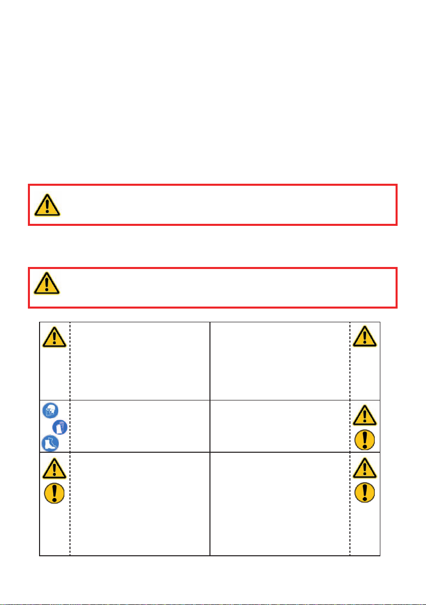
CAUTION!
The operating instructions for the hoses, the accessories and the connected
devices must also be heeded!
Even if you have already received instruction on how to use the equipment, you should still
read through the following safety instructions again.
CAUTION!
Ensure that the accessories and connected equipment are suitable for the
maximum operating pressure!
Please ensure that no body
parts or clothing get stuck
between the visibly moving
parts.
Wear protective clothing, safety
helmet with visor, safety shoes
and protective gloves.
Working under suspended
loads is not permitted where
such loads are being lifted only
by means of hydraulic devices.
If working under suspended
loads is unavoidable, suitable
mechanical props are also
required.
Immediately report any changes
that occur (including changes
in operating behaviour) to
the appropriate persons/
departments! If necessary, the
equipment is to be shut down
immediately and secured!
Check the equipment for visible
fl aws or damage before and
after use.
Check all lines, hoses and
screwed connections for leaks
and externally visible damage,
and repair immediately!
Escaping hydraulic fl uid can
cause injuries and fi res.
6
Page 7
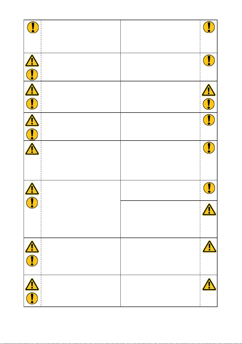
In the event of malfunctions,
immediately deactivate the
device and secure it. Repair the
fault immediately.
Do not carry out any changes
(additions or conversions) to the
equipment without obtaining the
approval of LUKAS beforehand.
Observe all safety and danger
information on the device and in
the operating instructions.
Please ensure that all safety
covers are present on the
equipment and that they are in
proper and adequate condition.
Safety devices must never be
disabled!
Make sure before switching
on/starting up the device and
during its operation, that this will
put no one in danger.
When working close to live
components and cables,
suitable measures must be
taken to avoid current transfers
or high-voltage transfers to the
equipment.
All safety and danger
information on the device must
always be complete and in a
legible condition.
Any mode of operation which
compromises the safety and/
or stability of the device is
forbidden!
The maximum operating
pressure set on the equipment
must not be changed!
Observe all intervals for
recurring tests and/or
inspections that are prescribed
or stated in the operating
instructions.
Only genuine LUKAS
accessories and spare parts are
to be used for repairs.
When working with this
equipment or when transporting
it, ensure that you do not get
caught up in the hose or cable
loops and trip.
The build-up of static charge
and therefore possible sparking
must be avoided when handling
the device.
Motorised pumps must not be
operated in areas at risk of
explosion!
Do not touch the engine and
exhaust system when running
with combustion engine pumps
because of the danger of
burning.
Combustion engines must not
be operated in enclosed spaces
because of the danger of
poisoning and / or smothering.
7
Page 8
If you spill any fuel when using
combustion engines, you must
remove the spilled fuel completely before starting the engine.
Keep combustion engines and
their fuels away from sources
of ignition since otherwise there
will be a danger of explosion.
Refuelling whilst the engine is
running is strictly prohibited!
All damaged electrical
components e.g. scorched
cables, etc. must be replaced
immediately!
In order to prevent the danger
of fi re, you should ensure
adequate ventilation when
operating combustion engines
and you must keep a safety
distance of at least 1m (39.4
in.) to walls and other screens.
Make sure that the combustion
engines are always standing on
as fl at and horizontal a surface
as possible to prevent fuel from
leaking out.
The equipment is fi lled with
hydraulic fl uid. This hydraulic
fl uid can be detrimental to
health if it is swallowed or its
vapour is inhaled. Direct contact
with the skin must be avoided
for the same reason. Also,
when handling hydraulic fl uid,
note that it can negatively affect
biological systems.
Make sure there is adequate
lighting while working.
Always keep these operating
instructions easily accessible at
the place of operation.
Damage to electrical
components must only
be repaired by a qualifi ed
electrician in compliance with
all applicable national and
international safety guidelines
and regulations.
When setting up the units, you
must make sure that they are
not impaired by the infl uences
of extreme temperatures.
When working with or storing
the equipment, ensure that the
function and the safety of the
equipment are not impaired
by the effects of severe
external temperatures or that
the equipment is damaged in
any way. Please note that the
equipment can also heat up
over a long period of use.
Before transporting the
equipment, always ensure that
the accessories are positioned
in such a way that they cannot
cause an accident.
Ensure the proper disposal of
all removed parts, leftover oil,
hydraulic fl uid and packaging
materials.
8
Page 9
The generally applicable, legal and other binding national and international regulations
pertaining to the prevention of accidents and protection of the environment apply and are to
be implemented in addition to the operating instructions.
WARNING/CAUTION!
The device is intended exclusively for the purpose stated in the operating instructions
(see chapter "Proper Use"). Any other use is not considered to be as intended. The
manufacturer/supplier is not liable for any damage resulting from use not as intended. The
user bears sole responsibility for such use.
Proper use includes observance of the operating instructions and compliance with the
inspection and maintenance conditions.
Never work in a fatigued or intoxicated state!
WARNING / CAUTION / ATTENTION!
However, if you still injure yourself on the hydraulic unit, clean the wound
immediately and consult a doctor to have it attended to!
If you get hydraulic fl uid in your eye, rinse it immediately several times with clear,
clean water and consult a doctor!
Also, if you swallow hydraulic fl uid you should consult a doctor!
9
Page 10
3. Proper use
LUKAS hydraulic power units are specially designed to supply LUKAS rerailing equipment
with hydraulic fl uid and pressure. LUKAS rerailing equipment, such as a traversing unit or
one or more hydraulic cylinders is used for erecting and rerailing of rail-bound vehicles.
Their use for supplying pressure / fl uid to rescue equipment of other manufacturers is
possible, yet requires the technical inspection and approval by LUKAS in each individual
case.
The equipment is not designed to operate without hoses or equipment (operating time
without hoses or equipment < 15 minutes).
The equipment type groups GC and PC 650 have been developed for rerailing technology
and for use in combination with the control table.
When working with the units described here, make sure that participating and non-participating
persons in the vicinity of the work and during the lifting procedure are not endangered by the
connected hoses and equipment.
WARNING / CAUTION / ATTENTION!
The safety instructions in this operating instruction manual concerning the site of
erection and type of erection must always be observed!
LUKAS units type GC and PC 650 are not explosion protected!
You can obtain accessories and replacement parts for the hydraulic power unit from your
authorised LUKAS dealer!
ATTENTION!
When selecting the units to connect to the unit, bear in mind that the maximum
possible useable volume of hydraulic fl uid is limited.
The sum of the max. required operating volume of oil (hydraulic fl uid) of all
connected equipment must not exceed the maximum possible usable volume
of the power unit!
NOTE:
Always register your hydraulic unit on the LUKAS Hydraulik GmbH internet site.
This is the only way to guarantee your extended warranty cover.
Before you use couplings from a different company , you must contact LUKAS or
an authorised dealer.
10
Page 11

4. Assembly marking
GC
Motor variants and
coding for hydraulic
power units
Valve variants:
2POWER = Simultaneous operation
4POWER = Four circuit operation
Motor variants:
PC = Electric motor (operation via mains supply)
GC = Petrol engine
650 E
Type group
with electric starter
-
2POWER
Valve variants
5. Functional description
5.1 General information
On all LUKAS hydraulic power units, a hydraulic pump is always driven by a motor
(combustion engine or electric motor).
The pump conveys hydraulic fl uid from the tank to the connected equipment and generates
the hydraulic pressure.
The fl uid distribution is then controlled by valves.
11
Page 12
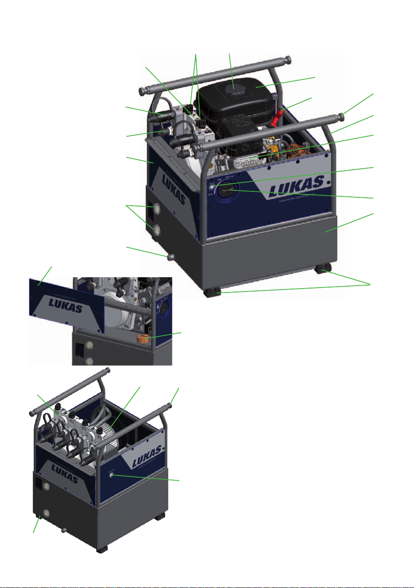
5.2 Layout of the units
4
9
8
12
2
7
17
13
15
10
14
20
18
14
1 Hydraulic fl uid tank
11
19
4
17
16
2 Petrol tank
3 Petrol engine with hydraulic pump
4 Connection block with control valves
(2 or 4 valves)
5 Engine switch
6 Electric starter button
7 Cable-pull starter
8 Valve control lever
9 Quick-disconnect coupling (female)
10 Quick-disconnect nipple (male)
11 Filler cover hydraulic fl uid
12 Filler cover petrol
13 Frame
14 Side cladding (clip fi xing)
15 Rubber buffer
16 ON - OFF -switch for electric motor
17 Telescopic carrying handle (can be
pulled out)
18 Drain screw for hydraulic fl uid
19 Electric motor with hydraulic pump
20 Sight window for hydraulic fl uid
3
6
5
1
15
12
Page 13

5.3 Motor variants
WARNING / CAUTION / ATTENTION!
For all motor variants, also comply with the separate operating instructions of
each motor manufacturer.
5.3.1 Electric motor
These hydraulic units are equipped with an electric motor. The electric motor is fed with power
from the mains or with power produced by generators. When operating with generators you
must make sure that voltage fl uctuations are not produced because these will have a direct
effect on the feed rate and durability of the hydraulic power unit.
The possible operating voltage and current frequency required can be taken from the
Chapter "Technical Data".
NOTE:
When connecting to the mains, if a very long connecting cable is used, the
power supply to the motor may be reduced as a result of the resistance in the
cable. This will reduce the power of the motor.
5.3.2 Petrol engine
These hydraulic units are equipped with a combustion engine driven by the fuel "petrol".
The units can be fi tted with an electric starter in addition to the cable-pull starter (optional).
NOTE:
The engine installed in the LUKAS power units does not match every detail of
the engine described in the manufacturer's separate operating instructions. On
account of the specifi c application in rerailing technology, and in order to ensure
the safety of the entire hydraulic power unit, components have been modifi ed
or adapted to suit.
Nevertheless, it is important that you follow all safety rules and operating,
maintenance and storage instructions in the separate engine instructions as
absolute since they are not affected by adjustments made by LUKAS.
The starter battery is automatically charged up by the integrated generator when the engine
is running. If the battery has become fl at after an extended storage period you should start
the unit with the cable-pull starter. This causes the battery to be charged up automatically.
If the battery is still not charged after running for about half an hour it could have the following
causes:
- the contacts (connection plug) have come loose and need to be reconnected.
- battery is defective and needs to be replaced.
- there is damage to the generator or the engine. In these cases you should contact
LUKAS customer service.
13
Page 14

5.4 Valve variants
The valves are always rigidly mounted in a connection block. This block is directly integrated
in the hydraulic power unit. The hoses (pressure and return) are always connected to the
connection block. The units are equipped with either a 2POWER or a 4POWER connection
block.
The hoses and equipment are connected with the connecting block via plug couplings.
5.4.1 Control valve "Two fl ow mode" (2POWER)
This valve enables the connection of two double-acting hydraulic units. With this valve you
can operate two units at the same time and independently of each other.
You have two switching possibilities. The two switching levers can be used to pressurise or
depressurise the individual connections.
5.5.2 Control valve "Four fl ow mode" (4POWER)
This valve enables the connection of four double-acting hydraulic units. With this valve you
can operate four units at the same time and independently of each other.
You have four switching possibilities. The four switching levers can be used to pressurise or
depressurise the individual connections.
ATTENTION!
When operating several rerailing units with one unit, ensure that the usable
volume of hydraulic fl uid in the reservoir is greater than the maximum possible oil
volume of all connected rerailing units. In the hydraulic fl uid tank, we differentiate
between the fi lling volume and the usable volume.
14
Page 15
5.5 Pumps
LUKAS hydraulic power units are fi tted with a two circuit or a four circuit pump, depending
on the type. The pumps are rigidly connected to the connecting block.
Double-fl ow pump for operating with 2POWER valve
For-fl ow pump for operating with 4POWER valve
The pumps used always have two pressure stages per pump feed fl ow, one low pressure
and one high pressure.
Low-pressure level (LP) = up to 14 MPa*
High-pressure level (HP) = up to 53 MPa*
The changeover from low pressure to high pressure is carried out automatically by the pump.
The maximum pressure is limited by a pressure limiting valve.
WARNING / CAUTION / ATTENTION!
For safety reasons, the pressure set on this valve must not be adjusted (without
the approval of LUKAS directly)!
*) 1 MPa = 10 bar
5.6 Frame with side sections
All the hydraulic power units described here are enclosed in a frame.
The frame and the side parts serve to protect the unit from external infl uences (e.g. dirt,
damage etc.) and also for transporting using the frame itself or the carrying handles.
The starter system on units having combustion motors are also mounted on the frame or the
side parts.
5.7 Connection to the control table
Connection to the rerailing equipment is exclusively via the control table. Either via the
connecting hoses rigidly fi xed to the control table or via additional pairs of hose extensions if
the power unit is not installed directly under the control table. The hose extension pairs are
supplied in various lengths.
The individual hoses can, if required, also be marked with coloured snap rings to make it
easier to allocate the hoses.
(For specifi c details, please consult the LUKAS range of accessories or contact your
LUKAS dealer.)
15
Page 16
6. Connecting the hoses / devices
ATTENTION!
When connecting the hose lines, always ensure that the connection components
are not dirty. If necessary, clean before connecting!
NOTE:
Before connecting or disconnecting the hoses on the hydraulic power unit, make
sure that the power unit is switched off or, with a unit with an electric motor (PC
650) that it is isolated from the mains (pull the plug out)! This represents an
increased safety measure in order completely to prevent any movement of the
equipment.
WARNING / CAUTION / ATTENTION!
Before connecting the equipment, make sure that allthe
components used are suitable for the maximum operating
pressure of the hydraulic unit! In cases of doubt, you must
consult LUKAS directly before connecting the equipment!
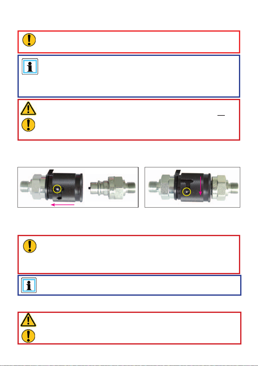
Coupling the Quick-disconnect couplings
The equipment is connected to the hydraulic pump via quick-disconnect coupling halves
(male and female).
X
Y
Before coupling, remove dust caps and then pull back and hold the locking sleeve of the
female coupling half (position X). Connect the male and female couplings and release the
locking sleeve. Then turn the locking sleeve to position Y. The connection has been made
and locked. Uncoupling is done in the reverse order.
ATTENTION!
Always couple the return line (tank line - marked T on the pump block) fi rst
and then the supply line (pressure line - marked P on the pump block)!
On disconnecting, you should always disconnect the supply line rst (pressure
line) and only then the return line!
NOTE:
Coupling is only possible if the hoses are depressurised.
For dirt protection, the supplied dust protection caps must be refi tted.
WARNING / CAUTION / ATTENTION!
Some quick-disconnect couplings have special functions.Therefore, you must
not unscrew them from the hoses or swap them over!
16
Page 17

7. Erection and start-up
7.1 Set-up
WARNING / CAUTION / ATTENTION!
Because of possible spark formation, combustion engine units and electrical
equipment must not be used in an explosion-risk area. Units with combustion
engines must not be used in enclosed spaces, as there is a danger of poisoning
and asphyxiation!
The unit is to be set up in a suitable location (secure location / fl at surface / suffi cient distance
from vehicles, loads, sources of ignition, etc.).
LUKAS units work perfectly at an angle of up to 10°. However, in order to guarantee maximum
safety and function, they should be operated in as horizontal a position as possible.
7.2 Start-up
NOTE:
Before commissioning for the fi rst time, or after longer periods of storage, on
units having a combustion engine, you must fi rst connect the starter battery and
check the oil level in the engine! If necessary, top up the engine oil!
For safety reasons, the LUKAS power units are supplied without engine oil,
hydraulic fl uid and fuel!
Proceed as follows to commission:
1. You must fi rst check the level of fl uids in the power unit.
The hydraulic fl uid level can be seen from the outside on the circular sight window at the
top and at the bottom of the tank. You should be able to see hydraulic fl uid in the top sight
window of the hydraulic tank. Set up the power unit horizontally and on an even surface in
order to be able to read the fl uid levels accurately or to top up. The fuel tank can be fi lled
ATTENTION!
Never mix up the fuel and hydraulic fl uid tanks when fi lling the tank; this can
damage the power unit!
up to the top of the petrol fi lter insert. A maximum of three litres of petrol should be poured
in, however, (correspondingly less if the power unit is resting at an angle).
2. On hydraulic power units with an electric motor, you must now connect the mains plug to
the power supply.
3. The hydraulic power unit must then be bled. Set all levers of the control valves to the
neutral position (see Chapter "Operation"). The actual venting is carried out in the units in
a different manner, depending on the drive motor:
a) Petrol engine:
- remove the plug lead from the sparking plug (on the back of the unit).
- slowly turn the engine over with the starter cable-pull several times.
- then replace the plug lead.
17
Page 18

b) Electric motor (mains operation):
- switch the motor on and switch it off again after approx. 15 seconds. Repeat
this process several times. (Before switching back on, the motor must be at a
standstill!)
This procedure makes sure that the pump draws fl uid slowly and is well bled. The hydraulic
fl uid tank is equipped with automatic bleeding, so that additional bleeding measures are
not required.
4. Check the levels of fl uid in the tanks again. If necessary, you should top up with fl uid.
8. Operation
ATTENTION!
The control levels on the hydraulic power units should always be switched to
the neutral position prior to starting the motor in order to prevent unwanted
movements of connected hydraulic equipment for safety reasons.
8.1 Starting the engines
8.1.1 Petrol engines
Before starting the combustion engines, check that the fuel tank is full and that the engine
oil level is within the permitted tolerances (petrol engines). If necessary, top up the relevant
fl uid (see also the operating instructions of the engine manufacturer in the scope of supply).
Engine starting procedure:
3. Set the engine switch to the "CHOKE" position
( ) (if the engine is warmed up, or if the ambient
temperature is higher, start the engine with the
switch in the "ON" position.)
4. Starting with the electric starter:
Push the starter button
Starting with the cable-pull starter:
Pull the handle on the cable-pull starter slowly up
to over the compression point (resistance is felt).
Allow it to go back to the starting position and then
pull it sharply all the way.
NOTE:
If the engine does not start after several attempts to start it, repeat the
procedure described above with the engine switch in the "ON" position.
5. Guide the handle on the cable-pull starter back into the starting position with your hand.
6. After 20 to 30 seconds warming up, turn the engine switch to the "ON" position (if it was
previously set to "CHOKE").
18
Page 19

8.1.2 Electric motors
Before starting the motor, check that all electrical connections and cables are in a good
condition. Then connect the mains cable (for motors with mains power supply) to the supply
socket.
Starting is carried out by pushing the ON/OFF switch on the side part of the power unit. The
ring around the switch lights up when the power unit is switched on.
ATTENTION!
Electric motors pull a very high start-up current for a short period. For this reason,
when using a generator, make sure that it can deliver the appropriate current.
The power supply must be fused with at least a 25 A fuse.
8.2 Stopping the engine
8.2.1 Petrol engines
The engine on the power unit stops automatically when the fuel tank is empty . However, you
should avoid this and switch it off before running to empty to prevent the carburettor from
running dry.
The following procedure is required for stopping the engine manually:
Engine stop procedure:
1. Check that all the connected equipment is in the basic position (start position).
2. Set the levers of the control valves to the neutral position (depressurised).
3. Set the engine switch to the "OFF" position.
WARNING / CAUTION!
Never touch the hot engine parts: this could result in severe burns.
8.2.2 Electric motors
Set the levers of the control valves to the neutral position (depressurised).
The motor is switched off again by pushing the ON/OFF button on the side part again. The
illumination of the switch goes out.
When the motor is switched off, the supply capability of the connected hydraulic pump is
also stopped.
19
Page 20

8.3 Topping up with fuel (only on combustion engines)
The engine must be switched off for refuelling!
Procedure:
1. Open the fuel tank cap.
2. Top up the tank with fuel to the maximum level (top of petrol fi lter insert).
WARNING / CAUTION / ATTENTION!
Be sure not to spill fuel. In particular, hot engine parts must not come into
contact with fuel; danger of fi re otherwise!
If fuel is spilled, it must be cleaned up immediately with a suitable absorbent
cloth. In doing so, be careful not to burn yourself on one of the hot engine
parts! The used cloth must then be cleaned or disposed of according to the
relevant provisions and guidelines!
3. Close the fuel tank again properly with the fuel tank cap.
8.4 Controlling the valves
ATTENTION!
The control levels on the hydraulic power units should always be switched to
the neutral position (de-pressurised) prior to starting the engine in order to
prevent unwanted movements of connected hydraulic equipment.
8.4.1 Control valve "Two fl ow mode" (2POWER)
There are two levers mounted on the connection block of this valve.
Each of the two small levers is assigned to one pressure port. The pressure
application of the corresponding pressure hose is controlled (" ") or the
connection is depressurised (" ") by switching the relevant lever over.
NOTE:
All switching levers must always be completely switched on up to the end stop.
20
Page 21

8.4.2 Control valve "Four fl ow mode" (4POWER)
There are four levers mounted on the connection block of this valve.
Each of the four small levers is assigned to one pressure port. The pressure
application of the corresponding pressure hose is controlled (" ") or the
connection is depressurised (" ") by switching the relevant lever over.
NOTE:
All switching levers must always be completely switched on up to the end stop.
21
Page 22

9. Dismantling the equipment / deactivation following operation
After completing the work and before stopping the unit, place all connected units to the base
setting (storage setting). You can then stop, or switch off, the motor on the unit, and if you
are using an electric motor this should be disconnected from the mains.
WARNING for power units with combustion engines!
Check that the engine switch is set to the “OFF“ position and remains there to
prevent the unwanted starting of the power unit!
Couplings:
ATTENTION!
The operating pressure in the system must be dissipated before uncoupling
the hoses.
When the rerailing work is complete you must release the operating pressure
in the installation/system.
If the connected hose lines are to be dismantled during shut-down, decouple as described
in Chapter "Connecting the hose lines". Then replace the dust protection caps onto the plug
couplings.
Clean any coarse contamination from the hydraulic tank before putting into storage. If the
storage period is extended then the unit must be cleaned completely externally and the
mechanically moving parts must be oiled.
If storing a unit with combustion engine, you should also remove the fuel from the fuel tank
and disconnect and/or remove the starter battery.
Avoid storing the hydraulic power units in a damp environment.
Observe the additional regulations in the separate operating instructions for the hoses.
CAUTION!
Several people may be required to transport to the storage location, depending
on the weight of the hydraulic power unit.
22
Page 23

10. T ests
The hydraulic power units are subject to very high levels of stress. A visual inspection must
therefore be carried out after every use and at least one visual inspection must be carried out
every six months. This reveals signs of wear in good time and punctual replacement of these
wear parts prevents damage to the equipment. Also check regularly that all the securing
screws are tightened (if applicable, comply with prescribed tightening torques).
Every three years or if there is any doubt regarding the safety or reliability of the equipment, a
functional test must also be performed. (Please also observe the relevant valid national and
international regulations pertaining to service intervals of hydraulic equipment). Operating
time per day In the Federal Republic of Germany, regular safety inspections according to
the regulations of the Gesetzlichen Unfallversicherung (GUV; connoted ‘Legal accident
insurance’) are mandatory.
ATTENTION!
Clean off any dirt before checking the equipment!
WARNING / CAUTION / ATTENTION!
To perform inspection, maintenance and repairs, personal safety equipment
appropriate for the work is an absolute requirement (if necessary also use
screening).
10.1 Recommended test intervals
10.1.1 Visual inspection
A visual inspection must be carried out after every use, but at least once every six months.
10.1.2 Function check
Operating time per day Functional test
up to 1 hour 1 x annually
up to 8 hours 1 x per quarter
up to 24 hours 1 x per month
In addition to these test intervals you need to carry out a function test if:
- the unit makes unusual noises,
- there is a justifi ed suspicion of internal damage to the unit.
If the noises and suspicions referred to above arise several times in a month, or if the
maximum pressure cannot be achieved during the function test, you need to contact LUKAS
customer service immediately . The contact details are given in the Chapter "Fault analysis".
23
Page 24

10.2 Hydraulic units with combustion engine
Visual Inspection
Hydraulic power units
• check that all hydraulic connections are still tight
• general tightness, no leaks (sweated oils do not have any infl uence on the function),
• is there any detectable damage to the engine, connecting blocks, on the frame or the side
sections,
• Is there any sign of damage to the hydraulics and/or fuel tank,
• Side plates present and tightened,
• Presence and legibility of the identifi cation plate, all actuation signs, instruction signs,
markings and warnings,
• The presence and perfect condition of all covers (e.g. exhaust defl ector),
• The presence and perfect condition of thermal protection mats,
• Is there still a minimum distance of 10 mm between the tanks and the hot parts of the
engine,
• All fl uid levels are within the specifi ed tolerances,
• Are the starters in proper working order and undamaged?
• Are the electrical cables in proper working order and undamaged?
• Is the electric starter battery in proper working order and undamaged?
• Couplings must be easy to couple,
• Dust protection caps must be available,
• All required accessory parts (e.g. sparking plug, sparking plug spanner and fuel can) are
present.
• Are the extending handles undamaged and functional
Functional test
• No unusual noises
• Starter functioning?
• Engine switch fully functional,
• Tests for maximum load (connect to control table and apply pressure with the valve
switching lever (a unit must not be connected to the control table) until the maximum
operating pressure is reached. Read-off via pressure gauge on control table).
24
Page 25

10.3 Hydraulic units with electric motor
Visual Inspection
Hydraulic power units
• Check that all hydraulic connections are still tight
• General tightness, no leaks (sweated oils do not have any infl uence on the function),
• Is there any damage apparent to the motor, valve blocks or on the casing?
• Side plates present and tightened,
• Presence and legibility of the identifi cation plate, all actuation signs, instruction signs,
markings and warnings,
• The presence and perfect condition of all covers (e.g. exhaust defl ector),
• All fl uid levels are within the specifi ed tolerances,
• ON/OFF switch in proper condition and not damaged,
• Couplings must be easy to couple,
• Dust protection caps must be available,
• All attached electrical parts (e.g. cables and plugs) are present and undamaged.
• Are the extending handles undamaged and functional
Functional test
• No unusual noises
• Tests for maximum load (connect to control table and apply pressure with the valve
switching lever (a unit must not be connected to the control table) until the maximum
operating pressure is reached. Pressure read-off via pressure gauge on control table).
10.4 Hoses (optional pairs of hose extensions)
Visual Inspection
Extension hoses
• Visual check for damage , cracks and leaks,
• Age check of the hoses (replace after latest 10 years),
• Hose connecting fi ttings with couplings on extension hoses tightly connected and not
leaking,
• Couplings must be easy to couple,
• Dust protection caps available?
25
Page 26

11. Maintenance and repair
11.1 General information
LUKAS hydraulic power units type GC and PC 650 have a complex structure and therefore
require only a small amount of maintenance. For general service work, special training
is not necessary; however, knowledge about the function of the power units, the legal
safety instructions and dealing with the required tools are basic prerequisites.
For safety reasons, repair work to the hydraulic power unit must only be carried out
ATTENTION!
Never use unnecessary force during maintenance work that could damage the
components of the power unit or compromise operational safety.
by the equipment manufacturer or by personnel specially trained for the purpose by the
equipment manufacturer, and by authorised LUKAS dealers.
WARNING / CAUTION / ATTENTION!
Protective clothes must be worn when maintenance and repairs are being
carried out, since the devices may also be pressurised when not in operation.
During work, ensure that all components are particularly clean, since dirt can
damage the rescue equipment!
ATTENTION!
Since LUKAS hydraulic units are designed for top performance, only those
components in the replacement parts lists for the relevant unit can be replaced.
Any other components in the unit may only be replaced if:
- You have participated in an appropriate LUKAS service training course.
- You have the express permission of LUKAS Customer Service (after request,
verifi cation that permission may be granted. An examination in each individual
case is necessary!)
When cleaning the equipment, please note that no cleaning agents must be used
having a pH value outside the range 5 - 8!
ATTENTION!
Attention must be paid to ensuring that no operating fl uids escape from units
with combustion engines during repair work!
26
Page 27

11.2 Service work on the hydraulic unit
11.2.1 Care instructions
The exterior of the device must be cleaned from time to time (not the electrical contacts)
and the metallic surfaces (not the electrical contacts) must be treated with a suitable agent
to protect against corrosion.
(In case of doubt, contact your authorised LUKAS dealer or LUKAS directly!)
11.2.2 Function and load test
If there is any doubt regarding the safety or reliability of the equipment, a function and load
test must also be performed.
11.2.3 Replacing the hydraulic fl uid
- The engine must be switched off or the unit must be isolated from the mains!
- After approx. 200 deployments, but after three years at the latest, replace the hydraulic fl uid.
- The fl uid is best replaced after it has warmed up.
- The used hydraulic fl uid must be disposed of properly.
27
Page 28

Procedure for hydraulic fl uid replacement:
1. Switch the engine off or isolate the electric motor from the mains. Place the power unit
on a slightly elevated base so that the drain plug for the hydraulic fl uid can be easily
reached.
2. Place a suitable collection vessel under the drain screw "A" or the hydraulic oil drain
opening into which it is screwed.
3. Remove the side panel to gain access to the hydraulic tank closure. Open the fi ller cap
"B", remove the drain screw "A" and the sealing ring "C" and let the hydraulic fl uid fl ow
into the prepared collection vessel (see illustration).
A
C
B
4. Fit the components "A" and "C" back in place in reverse order.
5. Pour the new hydraulic fl uid through the fi ller neck into the tank and close the neck again
with fi ller cap "B".
6. The unit then has to be bled again as described in the Chapter "Commissioning".
28
Page 29

11.2.4 Changing decals
All damaged and/or illegible decals (safety notices, type plate etc.) must be replaced.
Procedure:
1. Remove damaged and/or illegible decals.
2. Clean surfaces with industrial alcohol.
3. Affi x new decals.
Take care to affi x the decals in the correct positions. If this is no longer known, you should
ask your authorised dealer or contact LUKAS directly.
11.3 Additional service work on unit with combustion engine
(also observe the separate instructions from the engine manufacturer)
You must conduct the following service measures every 50 operating hours:
• Wash the air fi lter element. Reduce the maintenance intervals if being used in dirty or
dusty environments.
• Check the sparking plug and clean if required
You must conduct the following service measures every 100 operating hours:
• Replace the engine oil. Reduce the maintenance intervals if being used in dirty or
dusty environments.
You must conduct the following service measures every 200 operating hours:
• Set the electrode gap on the sparking plug
• Clean the fuel fi lter
You must conduct the following service measures every 500 operating hours:
• Replace the sparking plug and the fi lter element
• Clean and adjust the carburettor, valve clearance, valve seat and cylinder head.
You must conduct the following service measures every 1000 operating hours or every
2 years:
• Check the starter
• Inspect the engine for damage
• Replace the fuel line.
NOTE:
The fi rst engine oil change must be carried out after 20 working hours. The
subsequent oil changes should be carried out after 100 hours.
For dismantling the sparking plug, use a commercially-available sparking plug
spanner with universal joint and spanner size of 21 mm.
A straight / rigid sparking plug spanner would damage or break off the sparking
plug!
Also observe the separate engine manufacturer's operating instructions supplied
with the equipment!
29
Page 30

11.3.1 Replacing and cleaning the air fi lter
Keeping the air fi lter in good condition is extremely important.
Penetrating dirt leads to damage and wear in the engine in case of incorrect installation,
incorrect servicing or unsuitable fi lter inserts. Always keep the air fi lter insert clean.
Procedure:
1. Remove the rear side panel on the hydraulic power unit by releasing the fi xing clips and
lifting the panel away.
2. Release the fi xing hook for the protection cover at the bottom and remove the fi lter insert.
3. For cleaning, tap carefully to release the dirt and blow out the dust. Never use oil!
Wash the insert in clean water. Remove the water from the polyurethane insert by
squeezing (not twisting) as far as possible, and dry the insert.
5. Then re-fi t the fi lter.
Protective cover
Air fi lter insert
Fixing hook for protective cover
30
Page 31

11.3.2 Replacing, cleaning and setting the sparking plug
Procedure:
1. Remove the right side panel on the hydraulic power unit by releasing the fi xing clips.
2. Remove the sparking plug lead. The plug is very tight, but is only a push-fi t. However ,
when releasing it make sure that you do not tilt the plug or apply a side load to the
sparking plug. In the worst case, this can destroy the sparking plug and it can cause
expensive repairs as a consequence.
4. Unscrew the sparking plug from the engine using a sparking plug spanner with a universal
joint and having a size of 21 mm.
Sparking plug
connector
3. If the sparking plug is sooted-up you need to clean it with a sparking plug cleaning agent
or a brush. If the sparking plug is irreparably damaged (e.g. by burning out the electrodes
or by deformation) it must be replaced by a new one.
4. Set the electrode gap to 0.6 to 0.7 mm.
5. Then re-fi t the sparking plug.
Sparking plug
0.6 - 0.7 mm
11.3.3 Replacing the engine oil and the engine oil fi lter
For the procedure for replacing the engine oil and engine oil fi lter, please refer to the separate
operating instructions of the engine manufacturer! You need to remove the hydraulic tank
31
Page 32

from the power unit before you can drain the engine oil. See the relevant LUKAS spare parts
list.
Engine oil dipstick
(Engine oil fi ller
opening)
Oil drain screw
11.3.4 External charging or replacing the starter battery
Procedure:
1. Remove the left side panel "A" on the hydraulic power unit by releasing the fi xing clips "B".
2. You can now see the starter battery "C". First remove the negative terminal ("-") from the
battery and then the positive terminal ("+").
B
A
C
32
Page 33

3. If you want to charge the battery using an
external charger you need to connect it now.
(Observe the operating instructions for the
charger being used)
If the battery is defective it needs to be
replaced. To do this, release the fi xing strap "D"
by pulling the tab downwards and unhooking
it to the side. Remove the battery. Take care
when inserting the battery to make sure you
are doing it correctly (see illustration, left).
Installation of the battery is carried out in
CD
reverse order.
11.4 Couplings
WARNING / CAUTION / ATTENTION!
Couplings must not be repaired! They need to be replaced by genuine
LUKAS parts!
The quick-disconnect couplings must be replaced if:
- there is external damage,
- the locking does not function,
- hydraulic fl uid continues to leak in the coupled/uncoupled state.
Procedure for coupling to valve block:
1. First empty the hydraulic tank as described in the chapter "Replacing the hydraulic fl uid".
2. Unscrew the coupling half (nipple and/or sleeve).
3. Remove coupling part(s).
4. Screw the new part(s) into the valve block.
5. Screw in the coupling part(s) and tighten to a torque of M
6. The hydraulic fl uid tank must be refi lled and the power unit vented.
33
= 35 Nm.
A
Page 34

12. T roubleshooting
In the case of defects which directly affect the motor / engine, please consult the separate
operating instructions of the motor / engine manufacturer.
Fault Check Cause Solution
Electric motor
does not run after
actuating the switch
or does not achieve
full power
Check electric
motor connection
cable
Extension cable
or cable drum
used?
Mains cable not
connected
Defect in connection
cable
Cable not completely
uncoiled
Cable losses in
extension cable or
cable drums too great
(electrical resistance)
Connect mains cable
correctly
Shut down immediately
and have it repaired by
an authorised dealer,
engine manufacturer
or directly by LUKAS
Uncoil the mains cable
completely
Use a different suitable
extension cable or
cable drum.
Electric motor
connected to a
suitable battery?
Electric safety
device in power
supply has
triggered
Are all valves set
to pressure-free
(rest setting)?
Battery fl at Charge battery
Electric motor not
suitable for battery
operation
Power supply not
suitable for electric
motor
Electric safety device
in power supply has
triggered although it is
suitable for operation
of the motor.
Electric motor
defective or
overloaded due to a
different defect in the
unit
34
Connect the motor
to a different suitable
power supply
Connect the motor
to a different suitable
power supply
Safety device too
small, use a different
fuse.
Shut down immediately
and have it repaired by
an authorised dealer,
engine manufacturer
or directly by LUKAS
Page 35

Fault Check Cause Solution
Combustion engine
will not start
Check fuel level
in tank
Electric starter
present?
Check fuel line Fault in the fuel line Shut down immediately
Check starter
button and motor
switch
Hydraulic power
unit or engine
not suitable
for the working
environment
Check air fi lter Air fi lter contaminated Clean or replace the
Are all valves set
to pressure-free
(rest setting)?
Fuel tank empty Top up with fuel
Electric starter battery
fl at
Starter button or
cable-pull starter not
actuated
Engine switch not set
to Choke
Ambient temperature
too low
Not enough oxygen in
the air because of the
altitude of application
location of the
hydraulic motor
Combustion motor defective or overloaded
due to different defect
in the unit
Charge electric starter
battery or use cablepull starter
and have it repaired by
an authorised dealer,
engine manufacturer
or directly by LUKAS
Actuate starter button
or cable-pull starter
Set engine switch to
Choke
For the solution,
consult the separate
operating instructions
of the engine
manufacturer.
Use a different
hydraulic fl uid or
operating fl uid that
is suitable for the
relevant ambient
temperature (see
Chapter "Technical
Data")
Use a different more
suitable hydraulic unit.
Have the engine set to
the altitude of application by an authorised
dealer, engine manufacturer or LUKAS
direct (only if the unit is
to be used frequently
at this altitude).
air fi lter.
Have repaired by
authorised dealer,
engine manufacturer
or directly by LUKAS
35
Page 36

Fault Check Cause Solution
The engine is
running, but
the connected
equipment does
not move upon
activation of the
valve.
The connected
rescue equipment
does not move on
activation of the
valve, or moves
only very slowly or
unevenly.
Check hose Hose assembly not
connected properly or
damaged
Check the switch
position of the
valve lever on the
pump block of the
hydraulic unit
Connect a
different unit and
check whether
it works when
actuated
Connect a
different unit and
check whether
it works when
actuated
Check the switch
position of the
valve lever on the
pump block of the
hydraulic unit
Valve not switched
to supply line
pressurisation.
Defective pump unit Have it repaired by
The previously
connected unit is
defective.
Plug-in coupling
(female) defective
The previously
connected unit is
defective.
Pressure relief on
the unit is still active
(circulation at static
pressure)
Defective pump unit Have it repaired by
Air in hydraulic system Vent the hydraulic
Female coupling
defective
Check connection of
hose and reconnect if
necessary.
Switch valve to
pressure load of the
supply line.
authorised dealer or
directly by LUKAS
Rectifi cation see
operating instructions
of the connected unit
Replace plug-in
coupling (female)
Rectifi cation see
operating instructions
of the connected unit
Check the switching
positions of the
valve lever(s) and, if
necessary, reset (as
far as the end position)
authorised dealer or
directly by LUKAS
system
Replace the coupling
sleeve
36
Page 37

Fault Check Cause Solution
Connected
equipment does
not reach its end
position
Check hydraulic
fl uid volume in
hydraulic tank
Insuffi cient fl uid in the
hydraulic tank
Top up hydraulic fl uid
to the maximum fi ll
level
Attention! Before
topping up, return the
connected equipment
to the base position!
Connected
equipment does
not reach its
performance data
(force)
During function test:
A pressure gauge
installed between
the equipment
and the hydraulic
power unit does
not indicate the
maximum operating
pressure of the
power unit.
Check the
stated data of
the connected
equipment
Usable hydraulic fl uid
volume of the unit is
insuffi cient
Maximum permitted
operating pressure
of the pump is not
reached
Pump block defective Have it repaired by
Connected unit
defective
The operating
pressure of the
connected equipment
is locked internally
Connected unit
defective
Hydraulic unit
defective
Use a different unit
with a demand quantity
below the maximum
usable quantity of the
power unit
Have the pressure
limiting valve reset or
repaired by authorised
dealer or directly by
LUKAS
authorised dealer or
directly by LUKAS
Rectifi cation see
operating instructions
of the connected unit
No repair or fault
rectifi cation required
Consult the separate
operating manual
for the connected
equipment
Have it repaired by
authorised dealer or
directly by LUKAS
37
Page 38

Fault Check Cause Solution
Fluid coming out of
hydraulic fl uid tank
Leaking fl uid
between engine and
fl ange bearing
Hydraulic fl uid milky
and cloudy
Connected
unit not in rest
position yet and
fl uid coming out
of fi ller cap?
Fluid leaks from a
different location?
Returning the
hydraulic fl uid from the
equipment exceeds
the tank’s maximum
capacity.
Leak from tank, lines
or seals
Radial shaft seal
on the drive shaft is
defective
Water / condensation
in the system
Reduce fl uid level in
the hydraulic tank to
“Minimum” (bottom
sight glass), move
the unit to the base
position and then fi ll
back up with hydraulic
fl uid to the “Maximum”
level (top sight glass)
Replace defective
components or repair
by authorised dealer or
Lukas directly
Have it repaired by
authorised dealer or
directly by LUKAS
Replace the hydraulic
fl uid immediately
Hoses cannot be
coupled
Carrying handles
cannot be pulled out
or pushed in.
Carrying handles
cannot be locked or
unlocked
Hose reel does not
turn
Equipment cannot
be fi xed on the
equipment shelf
Pressure too high (e.g.
caused by ambient
temperature too high)
Coupling defective Coupling must be
Carrying handles are
still locked
Carrying handles or
frame defective
Carrying handles or
frame defective
Holding brake still
active
Hose reel defective Have it repaired by
Equipment shelf set
incorrectly
Equipment shelf
defective
Switch valve block to
circulation at static
pressure
replaced immediately
Unlock the carrying
handles and then pull
them out.
Replace the carrying
handles or the frame.
Replace the carrying
handles or the frame.
Release the holding
brake
authorised dealer or
directly by LUKAS
Reset the equipment
shelf to suit the
equipment.
Replace equipment
shelf.
38
Page 39

Fault Check Cause Solution
It is frequently not
possible to couple
hose assemblies
Hydraulic fl uid not
adapted to the
application situation
Hydraulic fl uid must be
replaced (see chapter
“Recommended
Hydraulic fl uids”)
Coupling defective Coupling must be
Leak from the
couplings
Fluid leak on the
hoses or the fi ttings
Damages on the
surface of the hoses
Contact an authorised LUKAS dealer or the LUKAS Customer Service Department directly
if the malfunctions cannot be rectifi ed.
The address for the LUKAS Customer Service department is:
LUKAS
A unit of the IDEX Corporation
Weinstrasse 39, D-91058 Erlangen, Germany
Tel.: (+49) 09131 / 698 - 348
Fax.: (+49) 09131 / 698 - 353
Hydraulik GmbH
Coupling defective Coupling must be
Leak, possible damage Replace hoses
Mechanical damage
or contact with
aggressive agents
replaced immediately
replaced immediately
Replace hoses
39
Page 40

13. T echnical data
Since all values are subject to tolerances, minor differences may occur between the data on
your equipment and the data in the following tables.
The values may also differ because of reading inaccuracies and/or tolerances in the
measuring equipment used.
NOTE:
The following tables contain only the most important Technical Data.
Additional data concerning your unit can be obtained from LUKAS on request.
40
Page 41

13.1 GC 650-2POWER
Device type GC 650-2POWER Units Remarks
Item number 70-10-10
Dimensions l x w x h 537 x 451 x 600 mm
21.1 x 17.8 x 23.6 in.
Operating
pressure
Delivery quantity High-
Change-over
pressure
Delivery quantity Low
Motor Power 4.2 kW Petrol, 4-stroke
Idle speed 3300 rpm
Volume of
hydraulic fl uid
Ambient
temperature
Weight 74 kg including hydraulic
Specifi cation of
hydraulic fl uid
Volume of petrol 3 l 4-stroke petrol
max. 53 MPa
7700 psi
2 x 0.9 l/min simultaneously
pressure
2 x 0.24 gpm
14 MPa from low to high
pressure
2000 psi
2 x 3.1 l/min simultaneously
pressure
2 x 0.82 gpm
max. 27.5 / 23 l Fill/useful volume,
horizontal
7.3 / 6.1 gal.
-20 … +55 °C
-4 … 131 °F
fl uid
163 lbs.
HM 10 ISO 6743-4
engine
0.8 gal.
1)
HD = High pressure 2) ND = Low pressure
41
3)
1MPa = 10 bar
Page 42

13.2 GC 650-4POWER
Device type GC 650-4POWER Units Remarks
Item number 70-10-20
Dimensions l x w x h 537 x 451 x 677 mm
21.1 x 17.8 x 26.7 in.
Operating
pressure
max. 53 MPa
7700 psi
Delivery quantity High-
4 x 0.7 l/min simultaneously
pressure
4 x 0.18 gpm
Change-over
pressure
14 MPa from low to high
pressure
2000 psi
Delivery quantity Low
4 x 2.6 l/min simultaneously
pressure
4 x 0.69 gpm
Motor Power 5.1 kW Petrol, 4-stroke
Idle speed 3600 rpm
Volume of
hydraulic fl uid
max. 45 / 40 l Fill/useful volume,
horizontal
11.9 / 10.6 gal.
Ambient
-20 … +55 °C
temperature
-4 … 131 °F
Weight 97 kg including hydraulic
fl uid
214 lbs.
Specifi cation of
HM 10 ISO 6743-4
hydraulic fl uid
Volume of petrol 3 l 4-stroke petrol
engine
0.8 gal.
1)
HD = High pressure 2) ND = Low pressure
42
3)
1MPa = 10 bar
Page 43

13.3 GC 650E-2POWER
Device type GC 650E-2POWER Units Remarks
Item number 70-10-15
Dimensions l x w x h 537 x 451 x 600 mm
21.1 x 17.8 x 23.6 in.
Operating pressure max. 53 MPa
7700 psi
Delivery quantity High-
pressure
Change-over
pressure
Delivery quantity Low
pressure
Motor Power 4.2 kW Petrol, 4-stroke
Idle speed 3300 rpm
Volume of hydraulic
max. 27.5 / 23 l Fill/useful
fl uid
Ambient
temperature
Weight 80 kg including
Specifi cation of
hydraulic fl uid
Volume of petrol 3 l 4-stroke petrol
2 x 0.9 l/min simultaneously
2 x 0.24 gpm
14 MPa from low to high
pressure
2000 psi
2 x 3.1 l/min simultaneously
2 x 0.82 gpm
volume,
horizontal
7.3 / 6.1 gal.
-20 … +55 °C
-4 … 131 °F
hydraulic fl uid
176 lbs.
HM 10 ISO 6743-4
engine
0.8 gal.
1)
HD = High pressure 2) ND = Low pressure
43
3)
1MPa = 10 bar
Page 44

13.4 GC 650E-4POWER
Device type GC 650-4POWER Units Remarks
Item number 70-10-25
Dimensions l x w x h 537 x 451 x 677 mm
21.1 x 17.8 x 26.7 in.
Operating pressure max. 53 MPa
7700 psi
Delivery quantity High-
pressure
Change-over
pressure
Delivery quantity Low
pressure
Motor Power 5.1 kW Petrol, 4-stroke
Idle speed 3600 rpm
Volume of hydraulic
max. 45 / 40 l Fill/useful
fl uid
Ambient
temperature
Weight 103 kg including
Specifi cation of
hydraulic fl uid
Volume of petrol 3 l 4-stroke petrol
4 x 0.7 l/min simultaneously
4 x 0.18 gpm
14 MPa from low to high
pressure
2000 psi
4 x 2.6 l/min simultaneously
4 x 0.69 gpm
volume,
horizontal
11.9 / 10.6 gal.
-20 … +55 °C
-4 … 131 °F
hydraulic fl uid
227 lbs.
HM 10 ISO 6743-4
engine
0.8 gal.
1)
HD = High pressure 2) ND = Low pressure
44
3)
1MPa = 10 bar
Page 45

13.5 PC 650-2POWER
Device type PC 650-2POWER Units Remarks
Item number 70-10-30
Dimensions l x w x h 537 x 451 x 577 mm
21.1 x 17.8 x 22.7 in.
Operating pressure max. 53 MPa
7700 psi
Delivery quantity High-
pressure
Change-over
pressure
Delivery quantity Low
pressure
Motor Power 2.2 (230/50) kW
Idle speed 2940 rpm
Volume of hydraulic
max. 27.5 / 23 l Fill/useful
fl uid
Ambient temperature -20 … +55 °C
Weight 76 kg including
Specifi cation of
hydraulic fl uid
2 x 0.7 l/min simultaneously
2 x 0.18 gpm
14 MPa from low to high
pressure
2000 psi
2 x 2.6 l/min simultaneously
2 x 0.69 gpm
single phase,
(VAC/
electric motor
Hz)
volume,
horizontal
7.3 / 6.1 gal.
-4 … 131 °F
hydraulic fl uid
168 lbs.
HM 10 ISO 6743-4
1)
HD = High pressure 2) ND = Low pressure
45
3)
1MPa = 10 bar
Page 46

13.6 PC 650-4POWER
Device type PC 650-4POWER Units Remarks
Item number 70-10-40
Dimensions l x w x h 537 x 451 x 672 mm
21.1 x 17.8 x 26.5 in.
Operating pressure max. 53 MPa
7700 psi
Delivery quantity High-
pressure
Change-over
pressure
Delivery quantity Low
pressure
Motor Power 3.5 (400/50) kW (VAC/
Idle speed 2980 rpm
Volume of hydraulic
max. 45 / 40 l Fill/useful
fl uid
Ambient
temperature
Weight 99 kg including
Specifi cation of
hydraulic fl uid
4 x 0.6 l/min simultaneously
4 x 0.16 gpm
14 MPa from low to
high pressure
2000 psi
4 x 2.2 l/min simultaneously
4 x 0.58 gpm
three-phase,
Hz)
electric motor
volume,
horizontal
11.9 / 10.6 gal.
-20 … +55 °C
-4 … 131 °F
hydraulic fl uid
218 lbs.
HM 10 ISO 6743-4
1)
HD = High pressure 2) ND = Low pressure
46
3)
1MPa = 10 bar
Page 47

13.7 Noise emissions of the power units
Device type Noise level L(WA)
Idle Full load
GC 650E-2POWER
GC 650-2POWER
GC 650E-4POWER
GC 650-4POWER
PC 650-2POWER 91 96
PC 650-4POWER 90 97
97 101
101 103
13.8 Sparking plug
Sparking plug type: BR6HS (NGK)
13.9 Sparking plug spanner
Sparking plug spanner with universal joint having a size
of 21 mm
13.10 Fuel
Lead-free petrol
Fuel:
ROZ 91 to ROZ 98
max. permitted bioethanol proportion: 10%
47
Page 48

13.11 Engine oil
13.12 Hydraulic fl uid recommendation
Mineral oil DIN ISO 6743-4 for LUKAS hydraulic equipment and others
Oil temperature range Oil designation Viscosity rating Remarks
A -20 .... +55°C HM 10 VG 10
Oil temperature range Oil designation Viscosity rating Remarks
A
recommended range of viscosity: 10...200 mm²/s (10…200 cSt.)
Supplied with HM 10 DIN ISO 6743-4.
-4.0 .... +131°F HM 10 VG 10
ATTENTION!
Before you use hydraulic fl uids from a different manufacturer, you must contact
LUKAS or an authorised dealer.
13.13 Operating and storage temperature range
Operating temperature [°C] / [°F] -20 … +55 -4 … +131
Environmental
temperature (device in
operation)
Storage temperature
(device not in operation)
[°C] / [°F] -25 … +45 -13 … +113
[°C] / [°F] -30 … +60 -22 … +140
48
Page 49

14. EC Declarations of conformity
49
Page 50

15. Notes
50
Page 51

51
Page 52

WARNING / CAUTION / ATTENTION!
Before connecting the equipment, make sure that
all the components used are suitable for the
maximum operating pressure of the hydraulic
unit! In cases of doubt, you must consult LUKAS
directly before connecting the equipment!
Please dispose of all packaging materials and
removed items properly.
LUKAS
A unit of the IDEX Corporation
Weinstrasse 39, D-91058 Erlangen, Germany
Tel.: (+49) 0 91 31 / 698 - 0
Fax.: (+49) 0 91 31 / 698 - 394
e-mail: lukas.info@idexcorp.com
www.lukas.com
Hydraulik GmbH
Made in GERMANY
© Copyright 2014 LUKAS Hydraulik GmbHGC_PC_650_power_units_manual_145000085_en.indd
Subject to changes
 Loading...