

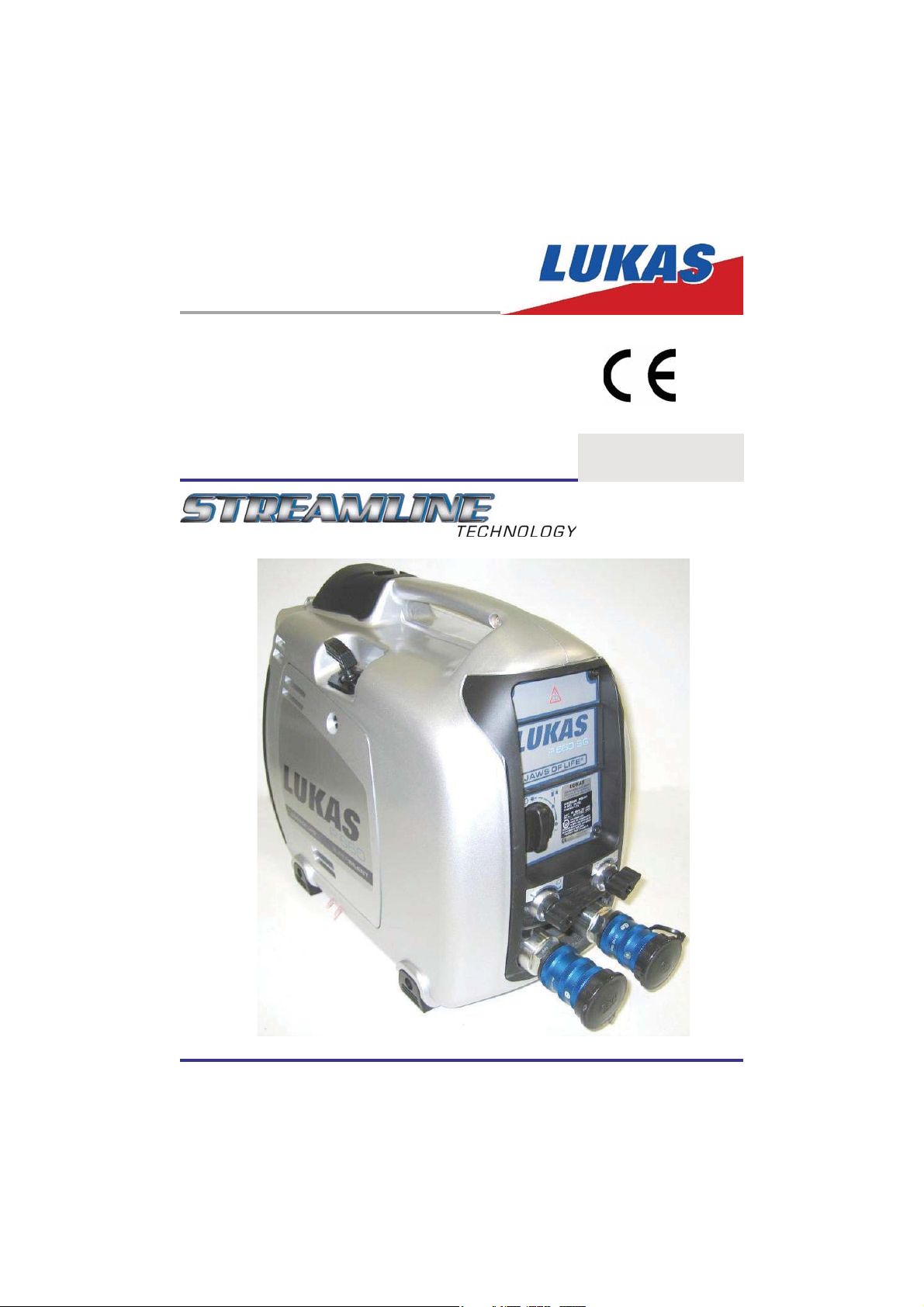
Operating instructions
Rescue equipment
P660SG SUPER SILENT
175325085 GB
Edition 07.2010
replaces 06.2008
(Translation of the original Operating Instructions)

Contents Page
1. Danger classes 3
2. Product safety 4
3. Proper use 7
4. Unit labelling 7
5. Functional description 8
5.1 General 8
5.2 Motor 9
5.3 Control valve 9
5.4 Pumps 9
5.5 Connection to rescue devices 9
5.6 Connection options 10
6. Connection of the hose lines 10
7. Installation and commissioning 11
7.1 Installation 11
7.2 Commissioning 11
8. Operation 14
8.1 Starting motors 14
8.2 Stopping motors 16
8.3 Controlling the valves 17
8.4 Opening the side parts 17
9. Removal of the device / Shutdown after operation 17
10. Care and maintenance 18
11. Repairs 20
11.1 General 20
11.2 Preventative service 20
11.3 Repairs 24
12. Troubleshooting 25
13. Technical data 28
13.1 Unit 28
13.2 Noise emissions 29
13.3 Spark plug 29
13.4 Fuel 29
13.5 Motor oil 29
13.6 Hydraulic uid recommendation 30
13.7 Operating and storage temperature ranges 30
14. Notes 31
2
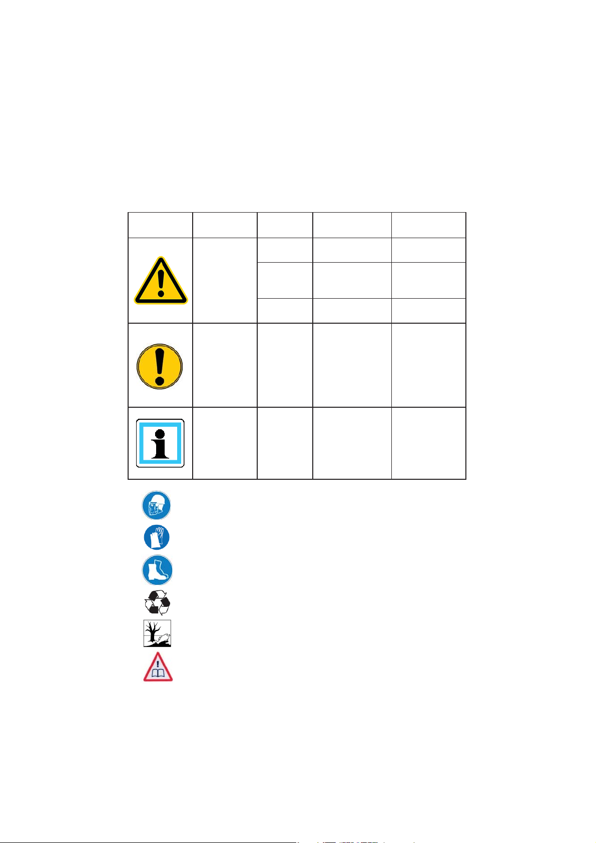
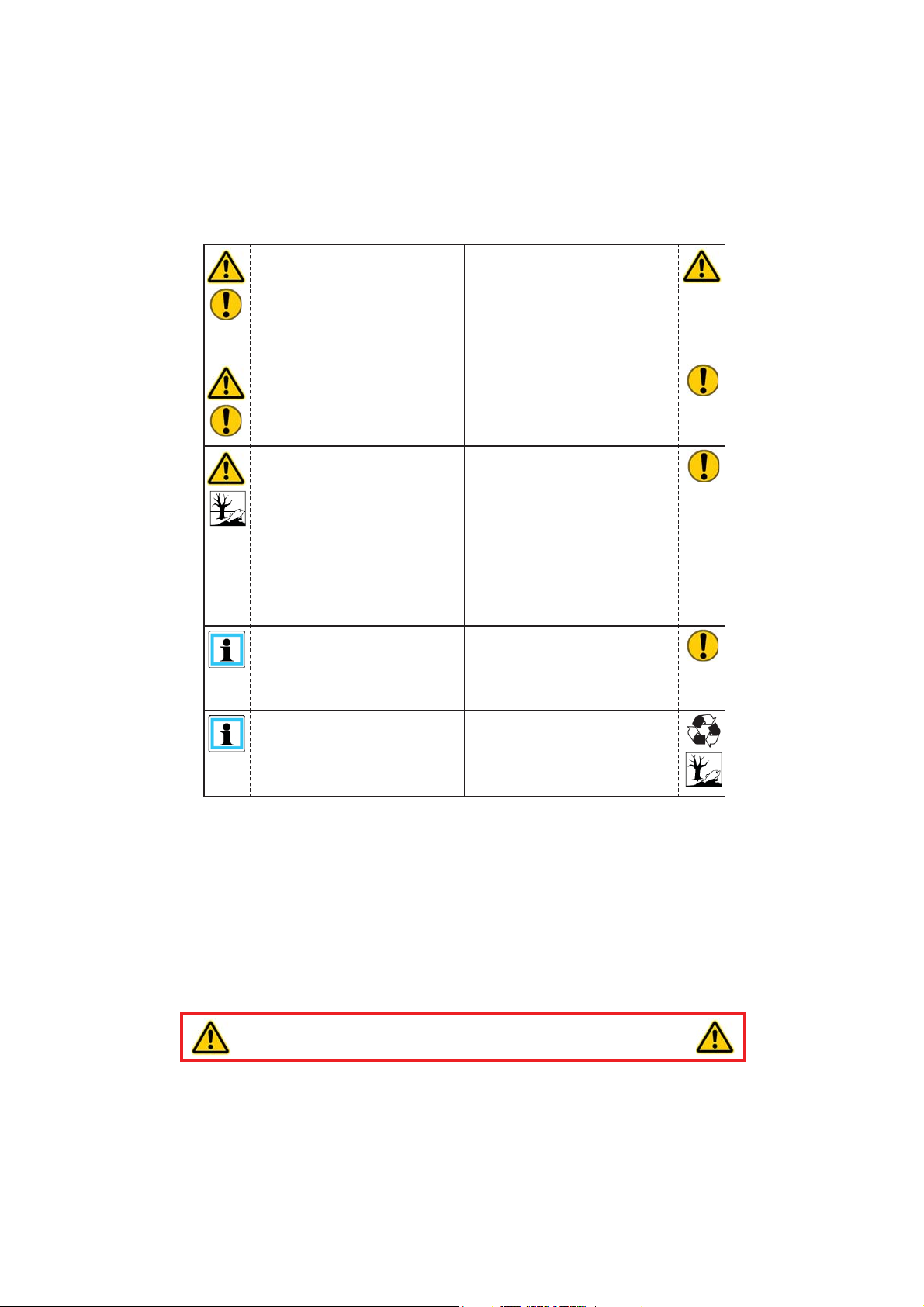
1. Danger classes
We distinguish between various categories of safety instructions. The table shown below
shows you the overview via the assignment of symbols (pictograms) and signal words the
concrete danger and the possible consequences.
Pictogram
Wear helmet with face guard
Damage /
injury to
human
device
- NOTE
Key word De nition Consequences
DANGER! Immediate danger
WARNING!
CAUTION!
CAUTION!
Potentially
dangerous
situation
Less dangerous
situation
Danger of damage
to device /
environment
Advice for
application and
other important /
useful information
and advice
Death or major
injury
Potential death or
major injury
Minor or slight
injury
Damage to the
equipment,
damage to the
environment,
damage to
surrounding
materials
No injury /
damage to
persons /
environment /
equipment
Wear protective gloves
Wear safety shoes
Proper recycling
Protect the environment
Read and follow operating instructions
3
2. Product safety
LUKAS products are developed and produced in order to ensure the best performance and
quality with proper use.
The safety of the operator is the most important consideration of the product design.
In addition, the operating instructions are to help use the LUKAS products safely.
In addition to the operating instructions, all generally applicable, statutory and other
binding rules for accident prevention and for environmental protection must be heeded and
disseminated.
The device must only be operated by educated persons who are trained in safety technology,
because otherwise there is a risk of injury.
We advise all users before using the device to carefully read through the operating instructions
and to follow the instructions contained therein without exception.
We also recommend that you get instructed by a quali ed trainer in the use of the product.
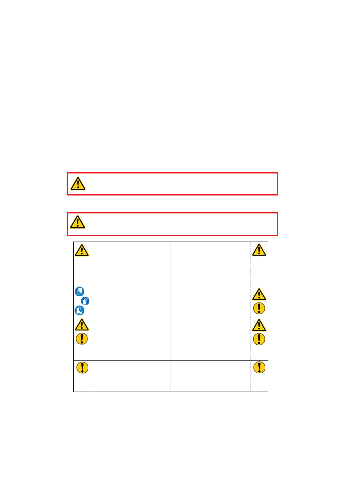
WARNING / CAUTION!
The operating instructions for the hoses, the accessories and the connected
devices must also be heeded!
Even if you have already received instruction, you should read the following safety instructions
again.
WARNING / CAUTION!
Make sure that the accessories used and the connected devices are suitable
for the max. operating pressure!
Make sure that no body parts
or clothing get between the
openly visible moving parts of
the device.
Wear protective clothing,
protective helm with visor,
safety shoes and protective
gloves.
Working under loads is
prohibited if they are raised
exclusively with hydraulic
devices. If this work is
unavoidable, suf cient
mechanical supports are
additionally required.
In the event of malfunctions,
shut down the device
immediately and secure it. You
should have the malfunction
repaired immediately.
Immediately report changes
that occur (including changes
in operating behavior) to
the appropriate persons/
departments! If necessary,
immediately shut down and
secure the device!
Check the device for visible
defects or damage before and
after use.
Check all lines, hoses and
screwed connections for leaks
and externally visible damages
and repair immediately!
Escaping hydraulic uid can
lead to injuries and res.
Do not make any changes
(add-ons or conversions) on the
device without the approval of
LUKAS.
4
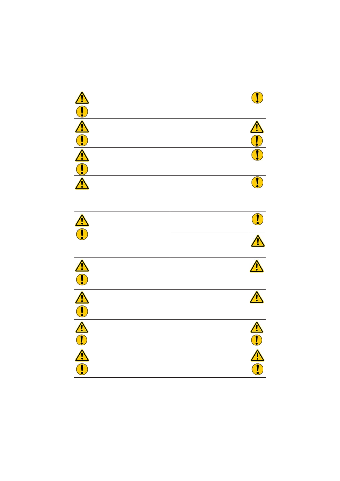
Heed all safety instructions
and hazard warnings on the
device and in the operating
instructions.
All safety instructions and
hazard warnings on the device
are to be kept intact and in a
legible condition.
Make sure that all safety covers
are present on the device and
in proper working condition.
Safety equipment must never
be disabled!
Before switching on/engaging
the device or while operating
the device, it must be ensured
that no one is endangered by
operating the device.
When working in the vicinity
of live components and lines,
take appropriate measures for
preventing current transfers or
high voltage ashovers to the
device.
The source of electrostatic
discharge with the possible
consequence of spark formation
when handling the device
should be prevented.
Motor pumps must not be
operated in areas at risk for
explosion!
Any work procedure that
detracts from the safety and/or
stability of the device should be
abandoned!
The maximum permissible
operating pressure must not be
changed.
Observe all intervals that
are prescribed or speci ed
in the operating instructions
for recurring tests and/or
inspections.
For repairs only original LUKAS
accessories and replacement
parts are to be used.
Make sure that you do not
get caught in the hose loops
and trip when working with or
transporting the device.
Do not come in contact with
the motor and exhaust system
because of the risk of burns.
Combustion engines must not
be operated in closed rooms
due to risk of poisoning and/or
suffocation.
If fuel is spilled on combustion
engines, it must be completely
removed before starting the
motor.
Keep combustion engines and
their fuel away from ignition
sources due to danger of
explosion.
Refuelling during operation of
a combustion engine is strictly
prohibited!
All damaged electrical
components (e.g. smouldered
cables etc.) must be promptly
replaced!
5
In order to prevent re hazard,
ensure suf cient ventilation
when operating combustion
engines and maintain a safety
distance of at least 1 m (39.4
in.) to walls and other shields.
Ensure that the combustion
engine motor pumps always
sit on a largely level horizontal
surface, so that no fuel can
leak.
The device is lled with
hydraulic uid. These hydraulic
uids can be detrimental to
health if they are swallowed or
the vapors thereof are inhaled.
Direct contact with the skin
should be avoided for the same
reasons. Also, when handling
hydraulic uids, note that they
can negatively affect biological
systems.
Make sure there is adequate
lighting while working.
Always keep these operating
instructions easily accessible
at the site where the device is
used.
Damage to electrical
components may only be
eliminated by a trained quali ed
electrician, in compliance with
all applicable national and
international safety guidelines
and regulations.
When the units are installed,
care needs to be taken that they
are not impaired by extremely
strong temperature effects.
When operating and/or storing
the device, make sure that the
function and the safety of the
device are not impaired by
strong external temperature
effects or that the device is
damaged. Consider that the
device can also heat up when it
is continuously used.
Before transporting the device,
always check to see that the
accessories are positioned
securely against the possibility
of an accident.
Make sure you properly dispose
of all removed parts, leftover
hydraulic uid, leftover oil and
packing materials.
In addition to the safety instructions of these operating instructions, all generally applicable,
statutory and otherwise binding national and international rules for accident prevention need
to be heeded and disseminated!
WARNING / CAUTION / ATTENTION!
The device is speci ed exclusively for the purpose represented in the operating
instructions (see Chapter "Proper use"). Any use that differs or goes beyond this is
considered improper. The manufacturer/supplier shall not be held liable for damages
resulting from improper use. The risk shall be borne solely by the user.
Proper use also includes heeding the operating instructions and complying with the inspection
and maintenance requirements.
Never work in a fatigued or intoxicated state!
6
3. Proper use
LUKAS hydraulic units are speci cally designed to supply LUKAS rescue equipment with
hydraulic uid so that they can be used to rescue victims in the event of accidents in road,
rail and air travel as well as in building rescues.
The use for the supply of pressure or uid to rescue equipment of other manufacturers
is possible, but requires the technical testing and approval of LUKAS on a case-by-case
basis.
WARNING / CAUTION / ATTENTION!
Make sure you always heed the safety tips contained in these operating
instructions with regard to the installation location and type! The units also may
not be operated in all atmospheres due to a possible danger of explosion!
Accessories and spare parts for the rescue equipment can be obtained from your authorized
LUKAS dealer!
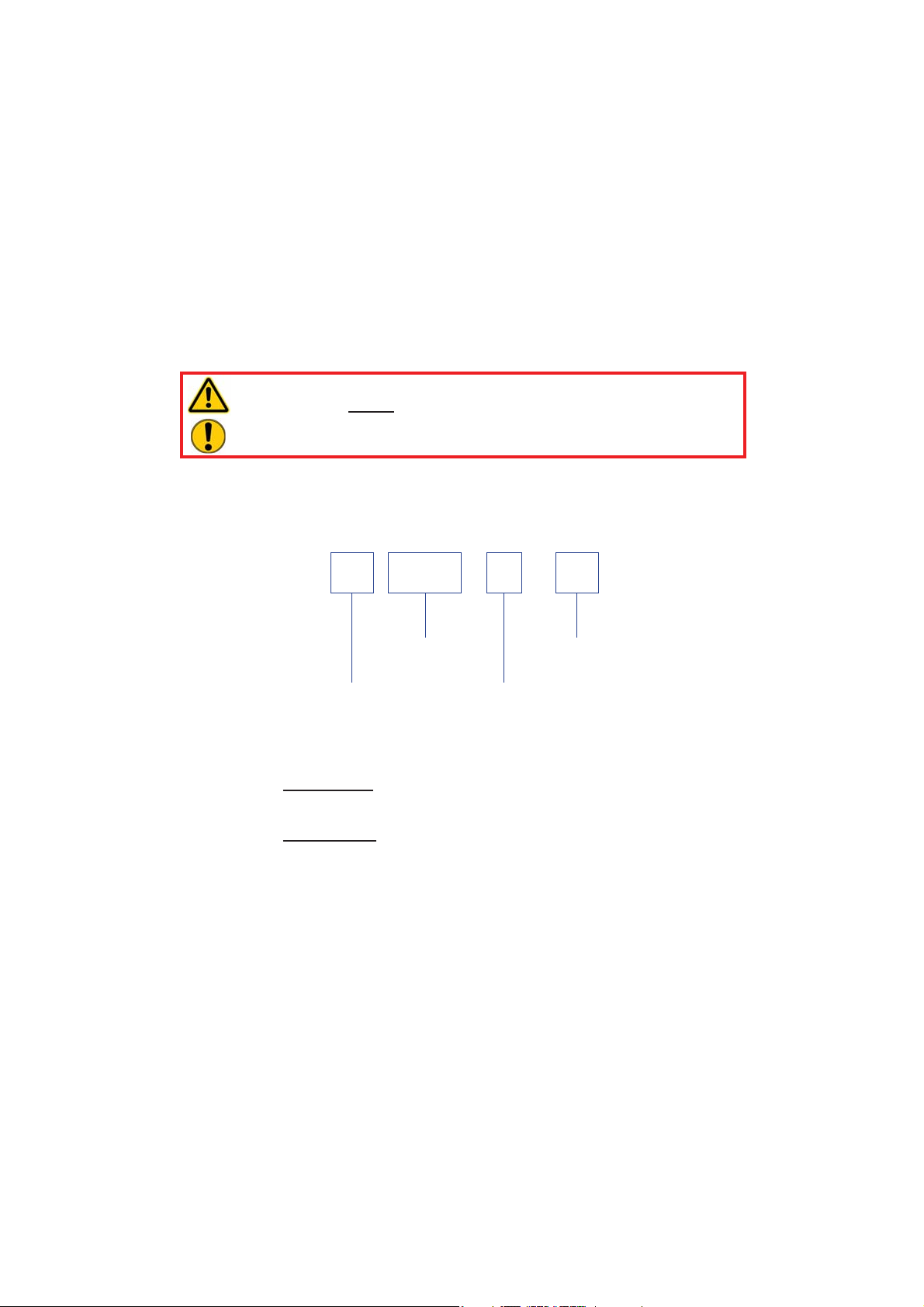
4. Unit labelling
P 660 S G
Type group
Codes for
hydraulic units
Valve variant:
S = Simultaneous operation
Motor variant:
G = Petrol-operated motor
Valve variant
7
Motor variant
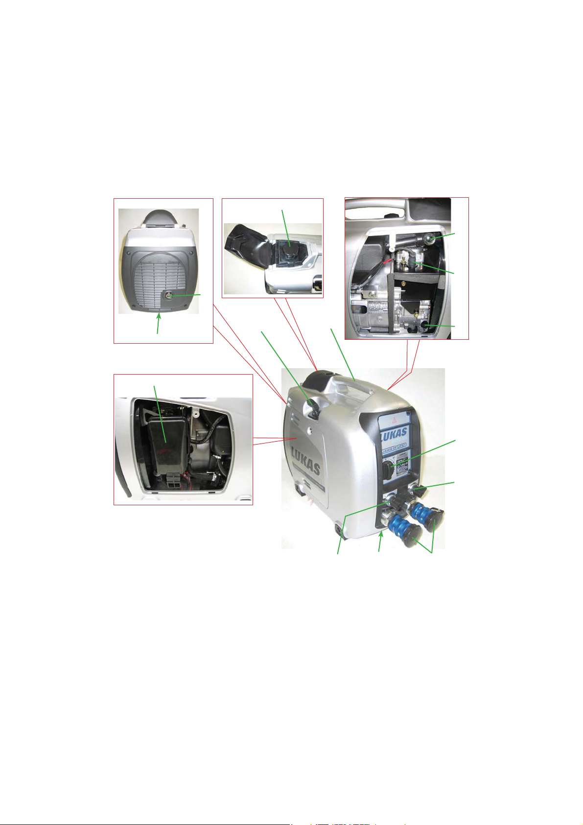
5. Functional description
5.1 General
The main components (see image) of each LUKAS hydraulic unit are:
6
5
8
10
11
7
1 Recoil starter
2 Motor switch
3 Control switch 1 for
hydraulic supply
4 Control switch 2 for
hydraulic supply
5 Exhaust
6 Tank ller (fuel)
7 Air lter
8 Filler neck for
hydraulic uid
1
left
device
side
13
right
device
side
3
9 Motor oil ller neck with oil dipstick
10 Spark plug socket
11 Motor oil drain plug
12 Drain plug for
hydraulic uid and
hydraulic uid lter
13 Carrying handle
14 Female monocoupling
12
14
9
2
4
8
In all LUKAS hydraulic units, a motor typically operates a hydraulic pump, which delivers
uid from the tank and builds the pressure. The distribution of the uid is then controlled by
integrated valves.
5.2 Motor
These hydraulic units are equipped with a 4-cycle combustion engine, which is operated with
petrol. (refer to chapter "Fuel")
5.3 Control valve
ATTENTION!
In the operation of multiple rescue devices with a unit, make sure that the usable
amount of hydraulic uid in the uid tank is greater than the maximum possible
amount of operating uid of all connected rescue devices together!
The installed valve makes it possible to supply two devices simultaneously with pressure.
The pressure supply of both hydraulic connections, and consequently the pressure supply of
the connected rescue devices, can be controlled by way of the two control switches.
5.4 Pumps
LUKAS SUPER SILENT units are equipped with a dual ow pump.
Dual ow pump 2 pump delivery ows
The pumps used are always equipped with two pressure circuits per pump delivery ow,
a low-pressure and a high-pressure circuit.
Low-pressure circuit (ND) = up to 14 MPa*
High-pressure circuit (HD) = up to 70 MPa*
The switch from low pressure to high pressure is automatic in the pump.
The maximum pressure is limited by a pressure control valve.
WARNING / CAUTION / ATTENTION!
For safety reasons, the pressure set at this valve must not be changed (without
the direct consent of LUKAS)!
*(1 MPa = 10 bar)
5.5 Connection to rescue devices
The connection to the rescue devices is created by extension hose pairs or hose reels. They
are offered in different lengths, anti-kink colours and different connection options.
The standard hose pairs from the LUKAS line of accessories are always equipped with
monocouplings on at least one end in order to connect them to LUKAS rescue devices. The
individual hose lines of a hose pair can be differentiated by the different colours in order to
avoid confusion of the pressure and return lines.
(For more details, please refer to the LUKAS line of accessories or contact your LUKAS
dealer.)
9
5.6 Connection options
The connections for the hydraulic hoses are always provided on the unit.
The unit is provided exclusively with monocouplings.
6. Connection of the hose lines
ATTENTION!
When connecting the hose lines, make sure that the connection components are
not dirty and if necessary clean immediately beforehand!
ATTENTION!
Only devices in the basic position may be connected to the unit in order to avoid
that an amount of hydraulic uid greater than the maximum ll quantity can enter
the tank of the unit!
WARNING / CAUTION / ATTENTION!
Before connecting devices, make sure that all components
used are suitable for the maximum operating pressure of the
hydraulic unit! In case of doubts, LUKAS must be consulted
directly before connecting the devices!
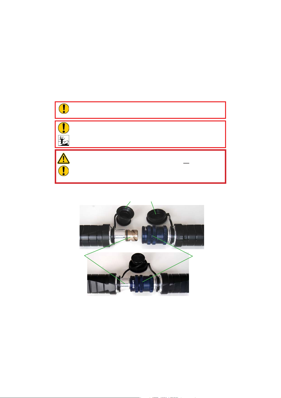
The hydraulic hoses are connected via quick-disconnect coupling halves (female and male)
to the hydraulic pump in such a way that they cannot be reversed.
Dust caps
Male coupling
Before coupling, remove dust caps, then connect male and female couplings and turn
locking sleeve of the female coupling in direction "1" until the locking sleeve engages. The
connection is then made and secured. The decoupling is accomplished by turning the locking
sleeve in direction "0".
The coupling of the devices under pressure is also possible, assuming the connected
equipment is not turned on.
10
Female coupling

NOTE:
We recommend, when ambient temperatures are low and extension hoses /
hose reels are used, connecting the coupling halves in a depressurised state
because decoupling may otherwise require a very large exertion of force.
For dust protection, the supplied dust caps must be reattached.
WARNING / CAUTION / ATTENTION!
The monocouplings must not be unscrewed and/or the hose lines reversed!
7. Installation and commissioning
7.1 Installation
WARNING / CAUTION / ATTENTION!
Due to the possibility of spark formation, combustion engine units must not be
used in areas at risk for explosion.
No units containing combustion engines may be used in closed rooms due to
risk of poisoning and/or suffocation!
The unit should be installed at a suitable site (secure location / at surface / suf cient distance
from vehicles, loads, ignition sources, etc.).
In order to ensure maximum safety and uid withdrawal quantities, you should operate the
unit in a horizontal position to the extent possible.
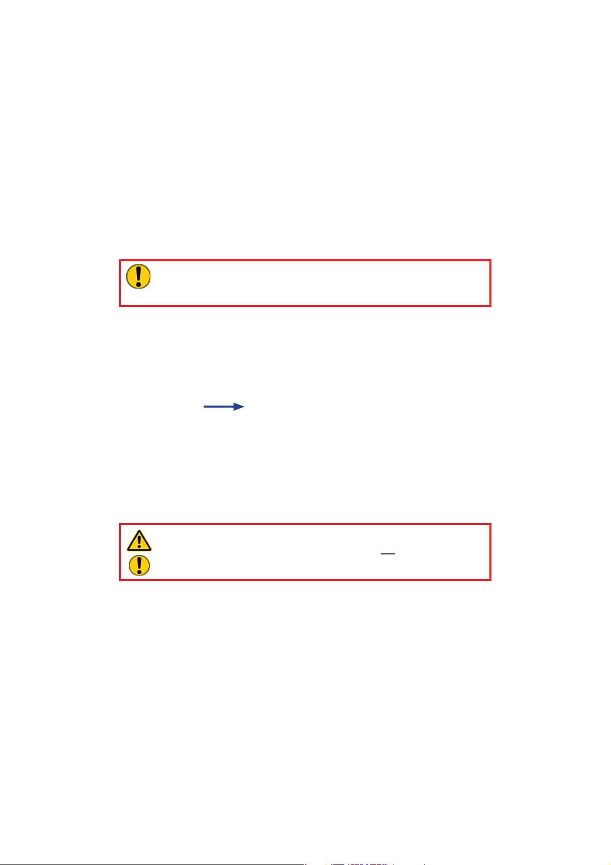
7.2 Commissioning
For commissioning, you should proceed in the following way:
1. First, check the uid levels of the unit. To do so, the unit must sit horizontally on a stable
and at surface and the motor must be switched off.
Procedure for motor oil level:
a) Remove the oil ller cap and check the oil level of
the motor (see gure on right).
b) If the oil level is below the lowest level, suitable
oil (refer to chapter "Motor oil recommendations")
must be replenished to the upper mark. When
checking the oil level, do not turn the oil ller cap.
c) Change the oil when the oil is dirty. (refer to chapter
"Repairs")
11
MAX.
MIN.
MIN.MAX.

Procedure for fuel level:
WARNING / CAUTION / ATTENTION!
Never add fuel while you are smoking or in the vicinity of naked ames!
a) When the tank is empty, ll it with unleaded
petrol.
b) The fuel level should never exceed the upper edge
on the fuel strainer. (see gure below)
c) It is essential that the fuel strainer is used on the
ller neck. (see gure on right)
d) When using the unit for the rst time, or when
stopping due to a lack of fuel, after replenishing
fuel pull the reversing starter handle several times
up to the upper edge of the fuel strainer of the
fuel tank.
Max. ll level
Fuel strainer
WARNING / CAUTION / ATTENTION!
To prevent re, read all warnings!
• Do not replenish the tank with the motor running or a hot motor!
• Before adding fuel, turn the motor switch to the 0 position (" ") = STOP!
• Ensure that no dust, dirt, water or other foreign matter can enter the fuel!
• Keep away from naked flames!
12

Procedure for hydraulic uid level:
a) Open the uid ller cap and check the hydraulic
uid level by looking into the ller pipe (see gure
below). If the bottom of the ller pipe is just barely
still covered with hydraulic uid, the unit is at the
lowest permissible hydraulic uid level. If the
hydraulic uid is almost in the angled part of the
ller pipe, the maximum permissible ll level has
been reached.
WARNING / CAUTION / ATTENTION!
If more uid is added than up to the
maximum permissible level, there is
a risk that the uid can leak. If the
hydraulic uid also drips onto hot
motor components, the re hazard is
extreme!
b) If the hydraulic uid level is below the lowest level,
suitable hydraulic uid (see chapter "Hydraulic
uid recommendations") must be replenished to
the maximum ll level.
Fluid ller cap
MAX.
MIN.
2. Before starting the motor, perform the following checks:
• Are there leaks in the fuel line?
• Are all screws and nuts tightened?
• Do individual components have damage or breakages?
• Are there leaks on the hydraulic lines and screw connections?
3. Thereafter, the hydraulic unit should be bled.
Procedure for hydraulic uid level:
a) Set all valve switches to "0".
b) Set the motor switch to "0".
c) Slowly crank the motor with the starter rope several times.
This procedure allows slow intake of the pump and good bleeding. The hydraulic uid
tank is equipped with automatic bleeding so that no additional venting measures are
required.
4. Check the hydraulic uid level in the tank again. If necessary, you should add uid to the
ll level.
13

5. The unit is now operational. To use it, place it on a suitable, level site!
WARNING / CAUTION / ATTENTION!
Observe the following:
• Remove easily ammable or other hazardous material from the surroundings
of the unit!
• Install the unit at least 1 m (39.4 in.) away from walls or other structures!
• Operate the unit only in a dry, well-ventilated area!
• Ensure than no foreign objects can enter the exhaust pipe!
• Do not bring naked flames in the vicinity of the unit! Do not smoke!
• Install the unit on a flat, stable surface!
• Do not block any air ducts of the unit with paper or other material!
6. Finally, you can connect the extension hoses and/or hose reels (as described in the
chapter "Connection of the hose lines").
8. Operation
8.1 Starting motors
Before starting the motor, perform all instructions from the chapter "Commissioning".
Flow chart for starting:
1. Check that all maintenance openings (side parts etc.) are connected to the unit; if not,
close them immediately.
2. Check that the valve switches are set to "0".
14
Valve switchValve switch

3. Set the motor switch to position " " (CHOKE)
(if the motor is warm, or the ambient temperature
is
high, start the motor with the switch in position
" " (RUN)).
4. Slowly pull the handle of the recoil starter until it
has crossed the compression point (resistance
becomes noticeable), allow it to return to the basic
position and then pull it through swiftly.
5. After starting, allow the starter handle to return to
the basic position, while you continue to hold it in
your hand.
NOTE:
If the motor does not start even after
several attempts, repeat the procedure
described above with the motor switch
in position " " (RUN).
6. After a warm-up phase of 20 to 30 seconds, set the motor switch to position
" " (RUN).
15

8.2 Stopping motors
The motor of the unit stops automatically when the fuel tank is empty.
If the motor should be stopped before that, the following procedure is required:
Flow chart for stopping:
1. Check that all connected rescue devices are in the original position (basic position).
2. Set the two valve switches to "0".
Valve switchValve switch
3. Set the motor switch to position " " (STOP).
WARNING / CAUTION!
Never touch the hot motor parts; it could cause severe burns.
16

8.3 Controlling the valves
Two switches are provided on the valve. Each switch is assigned to the pressure connection
beneath it. By ipping the respective switch, the pressurisation of the corresponding pressure
line can be controlled.
There are 2 control stages for each switch:
0 = Depressurised circulation (no pressure supply of the hydraulic line)
0 = Pressure supply of the pressure line
8.4 Opening the side parts
In order to gain access to the following parts for maintenance and repair work, take off the
corresponding side cover by removing the screw with a screwdriver or a coin.
Left side cover: air lter, fuel cock, etc.
Right side cover: oil level gauge, ignition coil, spark plug, hydraulic uid
lling, etc.
9. Removal of the device / Shutdown after operation
After the work is completed and before shutting down the unit, you should bring all connected
rescue devices into the basic position (storage position). Then you can stop the motor of the
unit.
Couplings:
If the connected hose lines are supposed to be removed during shutdown, decouple the
monocouplings as described in the chapter "Connection of the hose lines". Ensure that you
place the dust caps again on the monocouplings.
Clean the hydraulic unit before storing it to remove dirt caused by the use.
With a longer storage time, the outside of the device should be cleaned and the mechanical
moving metal parts need to be oiled. You should also drain the fuel from the tank.
Avoid storing the hydraulic units in a damp environment.
17

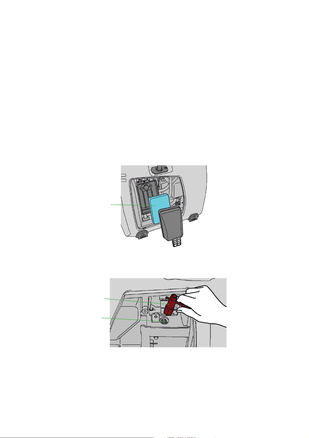
Additional measures on the motor for longer storage periods:
If the unit will not be used for a period of 6 months or more, the following measures
must be taken:
• Loosen the fuel line and carefully drain the
tank.
The quality of petrol remaining in the tank
deteriorates, and starting the motor becomes
more dif cult.
• Use a hand pump to drain the fuel from the
tank and insert it in the lling port.
• Loosen the drain plug on the carburettor.
• Replace the motor oil.
• Check to ensure that no screws and nuts have
become loose, if necessary retighten them.
• Pull the handle of the recoil starter until you
feel resistance and leave the handle in its
position.
Drain plug on
the carburettor
10. Care and maintenance
The hydraulic units are subject to very high mechanical stresses. Therefore, a visual inspection
needs to be made after each use, but at least once every half-year.
In this way, early signs of wear are recognizable so that damage to the device can be avoided by
prompt replacement of these wear parts. Also check regularly to make sure that all attachment
screws are tightened (heed any applicable tightening torque speci cations).
Every 3 years, or if there is a doubt about the safety or reliability, a functional check should
be also performed (For this purpose, also heed the corresponding applicable national and
international speci cations related to the maintenance intervals of rescue devices). In the
Federal Republic of Germany, regular safety technology tests are prescribed in accordance
with the regulations of the Statutory Accident Insurance (GUV).
ATTENTION!
Clean the device before checking for dirt!
WARNING / CAUTION / ATTENTION!
To perform maintenance and repairs, personal safety equipment appropriate for
the work is an absolute requirement. (incl. shields).
LUKAS offers a corresponding test set for the functional check of the hydraulic units.
(For more details, please refer to the LUKAS line of accessories or contact your LUKAS
dealer.)
18

Visual inspection
Hydraulic unit
• are all hydraulic connections still tightened,
• generally sealed, no leaks present (oil "sweat" has no effect on the operation),
• is damage visible on the motor, hydraulic components or the housing,
• are identi cation plate, all control decals, instruction decals, labels and warnings
present and legible,
• are all covers (e.g. exhaust cover) in place and undamaged,
• are all uid levels within the prescribed tolerances,
• is the recoil starter in proper working condition and undamaged,
• couplings easy to connect,
• dust caps in place,
• are all required accessory parts (such as spark plug, spark plug wrench and fuel can)
present.
Operational check
• no suspicious noises,
• tests at maximum load.
(Recommendation: Use the LUKAS test set, including test instructions, for the functional
check).
Additional maintenance measures on the motor:
Every 50 operating hours you must perform the following maintenance measures:
• Wash the air lter element. More frequently when used in dirty or dust surroundings.
• Check the spark plug and clean it, if necessary.
Every 100 operating hours you must perform the following maintenance measures:
• Change the motor oil. More frequently when used in dirty or dust surroundings.
Every 200 operating hours you must perform the following maintenance measures:
• Set the spark plug gap.
• Clean the fuel lter.
Every 500 operating hours you must perform the following maintenance measures:
• Replace the spark plug and lter element.
• Clean and/or adjust the carburettor, tappet clearance, valve seat and cylinder head.
Every 1,000 operating hours or every 2 years you must perform the following maintenance
measures:
• Check the starter.
• Replace the rubber assembly block of the motor.
• Inspect the motor.
• Replace the fuel line.
NOTE:
The rst motor oil change must be carried out after 20 working hours. Subsequent
oil changes each are due after 100 hours.
19

11. Repairs
11.1 General
Service work may only be performed by the device manufacturer or by personnel trained by
the device manufacturer and authorized LUKAS dealers.
For all components, only original LUKAS replacement parts may be supplied in exchange,
as are listed in the spare parts list, because in this way also any required special tools,
assembly instructions, safety aspects, tests absolutely must be taken into consideration (see
also the chapter "Care and maintenance" for more information).
During the assembly work, pay particular attention to the cleanliness of all components
because dirt can damage the rescue equipment!
WARNING / CAUTION / ATTENTION!
Wear protective clothing when making repairs because the devices may be
under pressure even in the idle state.
NOTE:
Always send the warranty tab back to LUKAS hydraulics GmbH. Only in this way
will you have a claim to the extended warranty coverage.
ATTENTION!
Because LUKAS hydraulic units are designed for the highest performance,
only components may be replaced that are listed in the spare parts lists of the
corresponding unit.
Additional components of the units may only be replaced if:
- You have participated in a corresponding LUKAS service training course.
- You have the express permission of LUKAS customer service (by request,
check on the grant of permission. A check is necessary in each individual
case!).
NOTE:
Do not perform any repairs without the corresponding LUKAS spare parts list,
because necessary tightening torques for screw connections and/or in some
cases also important additional information are listed there.
ATTENTION!
Ensure that no fuel can escape during the repair work on the units!
11.2 Preventative service
11.2.1 Care instructions
The exterior of the device needs to be cleaned from time to time and the metallic surfaces
need to be rubbed with oil to protect against corrosion.
11.2.2 Function and stress test
If there are doubts about safety or reliability, a function and stress test needs to be performed.
LUKAS offers the appropriate test equipment.
20

11.2.3 Replacing the hydraulic uid
- Replace the hydraulic uid after approximately 200 uses, however at the latest after three
years.
- Whenever possible, the replacement of the uid should be carried out when the unit is at
the operating state temperature.
- The motor must be switched off!
- The replaced hydraulic uid must be disposed of properly.
Procedure:
1. Place the collection pan under the drain plug for the hydraulic uid of the unit.
2. Loosen the tank ller cap and drain plug "A" of the unit and ll uid in the provided collection
pan. To do so, the hydraulic unit may also be slightly tilted.
C
B
A
3. Remove the hydraulic uid lter "B" and O-ring "C" located beneath and clean or replace
it, if necessary.
4. Install everything again in reverse order. (If damaged, replace the drain plug with the
sealing ring.)
The tightening torque of the drain plug is M
5. Fill the new hydraulic uid into the tank through the re ll tap.
= 40 Nm.
A
6. Finally, the unit must be bled again, as described in the chapter "Commissioning".
21

11.2.4 Replacing the motor oil
- Replace the motor oil after approximately 100 operating hours.
- Whenever possible, the replacement of the uid should be carried out when the unit is at
the operating state temperature.
- The motor must be switched off!
- The replaced motor oil must be disposed of properly.
Procedure:
1. Place the collection pan under the drain plug for the motor oil of the unit.
2. Loosen the oil ller cap and oil drain plug of the unit and ll uid in the provided collection
pan.
3. Then install them again. (If damaged, replace the oil drain plug.)
4. Fill the new motor oil into the motor up to the upper level on the oil cap.
22
Motor oil
drain plug
11.2.5 Replacing and cleaning the air lter
It is very important to maintain the air lter in a good state.
Dirt penetrating due to incorrect installation, incorrect maintenance, or unsuitable lter inserts
leads to damage and wear on the motor. Always keep the air lter insert clean.
Procedure:
1. Unhook the cover and remove the lter insert.
2. Paper insert:
In order to clean it, carefully tap it to loosen any dirt and then blow off the dust. Never use
oil! Clean the paper insert every 50 operating hours and replace it every 200 hours or
once a year.
3. Urethane foam:
Wash out the insert with fresh water. Squeeze out the water and dry the insert.
(DO NOT TWIST!!!)
4. Then reinstall the spark plug.
Air lter
11.2.6
Procedure:
1. Remove the spark plug from the engine using a suitable spark plug wrench.
Replacing and cleaning the spark plug and setting the spark plug gap
Spark plug
wrench
Spark plug
23

2. If the spark plug is covered with soot, you must remove the soot with a spark plug cleaner
or a brush. If the spark plug is irreparably damaged (e.g. due to melt-off of the electrodes),
it must be replaced by a new one.
3. Set the gap between the electrodes to 0.6 to 0.7 mm.
0.6 - 0.7 mm
4. Then reinstall the spark plug.
11.3 Repairs
To perform the allowed repairs, observe the corresponding spare parts lists with the remarks
and drawings illustrated thereon.
Should ambiguities persist with respect to the repair, please consult your authorized LUKAS
dealer or LUKAS customer service.
11.3.1 Monocouplings
The monocouplings must be replaced if:
- exterior damage is present,
- lock does not function,
- in the coupled and/or decoupled state, hydraulic uid continuously escapes.
Procedure:
1. Unscrew the coupling from the valve block.
2. Screw new coupling into the valve block with a torque of M
WARNING / CAUTION / ATTENTION!
Couplings should not be repaired; they should be replaced with original LUKAS
parts!
= 40 Nm.
A
11.3.2 Changing decals
All damaged and/or illegible decals (safety instructions, name plates, etc.) must be replaced.
Procedure:
1. Remove damaged and/or illegible decals.
2. Clean surfaces with acetone or industrial alcohol.
3. Adhere new decals.
Make sure to adhere the decals in the correct positions. If this is no longer known, you should
consult your authorized LUKAS dealer or contact LUKAS directly.
24

12. Troubleshooting
Problem Cause Remedy
Motor does not start Fuel tank empty Add fuel
Lever not set to choke Set lever to choke
Motor runs, but connected
rescue device does not
move when the valve is
actuated
Connected rescue
device moves slowly or
inconsistently when the
valve is actuated
Motor runs, but connected
rescue device does not
move, or only very slowly,
when the valve is actuated
Spark plug socket not
attached correctly
Spark plug dirty Clean the electrodes of the
Spark plug defective Replace the spark plug.
Combustion engine
defective
Ambient temperature too
low
Hose line not properly
connected or damaged
Valve not switched to
pressurisation of the
supply line
Valve defective Repair by authorised
Pump unit defective Repair by authorised
Female monocoupling
defective
Air in the hydraulic system Bleed hydraulic system
Valve defective Repair by authorised
Pump unit defective Repair by authorised
Valve defective Repair by authorised
Pump unit defective Repair by authorised
Female monocoupling
defective
Press the spark plug
socket rmly onto the
spark plug
spark plug
Repair by authorised
dealers, engine
manufacturer or by LUKAS
directly
Use other, more suitable
unit
Check connection of the
hose line and reconnect it
if necessary
Switch valve to
pressurisation of the
supply line
dealers or by LUKAS
directly
dealers or by LUKAS
directly
Replace female
monocoupling
dealers or by LUKAS
directly
dealers or by LUKAS
directly
dealers or by LUKAS
directly
dealers or by LUKAS
directly
Replace female
monocoupling
25

Problem Cause Remedy
Connected rescue device
not reaching its limit
position
Connected rescue device
does not achieve its
power-related performance
data
Fluid leaks on the
hydraulic uid tank
(especially at the re ll tap)
Hydraulic uid with milky
cloudiness
Hose lines cannot be
coupled
Hose lines frequently
cannot be coupled
Leakage at the couplings Coupling defective Coupling should be
Fluid level in the hydraulic
tank too low
Usable hydraulic uid
quantity of the unit is
insuf cient
Max. permissible operating
pressure of the pump is
not reached
Due to return ow of
the hydraulic uid from
the rescue device, the
maximum ll quantity of
the tank is exceeded
Seals defective Repair by authorised
Water or condensation
water in the system
They are under excessive
pressure (e.g. due to
excessive ambient
temperature)
Coupling defective Coupling should be
Hydraulic uid of the
application situation not
adapted
Coupling defective Coupling should be
Add hydraulic uid up to
max. ll level
Attention: move the
rescue device back into
the basic position before
adding uid!
Use a different rescue
device with a usable
quantity below the
maximum usable quantity
of the unit
Have pressure control
valve recalibrated or
replaced by an authorised
dealer or directly by
LUKAS
Lower the ll level in the
hydraulic uid tank to the
maximum
dealers or by LUKAS
directly
Perform hydraulic uid
change immediately
Depressurise valve
replaced immediately
Hydraulic uid needs
to be changed (see the
chapter “Hydraulic uid
recommendation” for more
information)
replaced immediately
replaced immediately
26

If the defects cannot be remedied, notify an authorized LUKAS dealer or contact LUKAS
Customer Service directly!
The address of LUKAS customer service is:
LUKAS
Weinstraße 39, D-91058 Erlangen
Postfach 2560, D-91013 Erlangen
Phone: (+49) 09131 / 698 - 348
Fax.: (+49) 09131 / 698 - 353
Hydraulik GmbH
27

13. Technical data
Because all values are subject to tolerances, there cannot be any differences between the
data of your device and the data of the following tables!
13.1 Unit
Device type P 660 SG
Ref.no. 175325000
Dimensions
l x w x h
Motor type 4-stroke gasoline engine
Motor power
Rotational speed
max. operating
pressure (HP)
max. operating
pressure (LP)
1)
2)
Flow rate (HP)
Flow rate (LP)
2)
max. ll quantity
max. usable
quantity
Weight (incl. all
max. uid ll levels)
Ambient
temperature
Valve variant Simultaneous operation
Max. connection
options of devices
Connection system Monocoupling
[mm] 585 x 300 x 450
[in.] 23.03 x 11.81 x 17.72
[kW] 2,1
[HP] 2.82
-1
[min
]
[rpm.]
3)
[MPa]
[psi.] 10,153
3)
[MPa]
[psi.] 2,031
[l/min] 1 x 0,5
1)
[gal.-US/min] 1 x 0.13
[l/min] 1 x 2,5
[gal.-US/min] 1 x 0.66
[l] 3
[gal.-US] 0.79
[l] 2,4
[gal.-US] 0.63
[kg] 30
[lbs.] 66.1
[°C] - 20 … + 55
[°F] - 4 … + 131
4000
70
14
2
1)
HP = high pressure 2) LP = low pressure
28
3)
1MPa = 10 bar

13.2 Noise emissions
Device type P 660 SG
Ref.no. 175325000
idle running
(measuring distance: 1m)
full load
(measuring distance: 1m)
idle running
(measuring distance: 5m)
full load
(measuring distance: 5m)
[dB(A)] 77
[dB(A)] 79
[dB(A)] 69
[dB(A)] 73
13.3 Spark plug
Spark plug type: BMR4A (NGK)
13.4 Fuel
Fuel: unleaded regular
13.5 Motor oil
Multi-purpose oil
Ambient
temperature
29

13.6 Hydraulic uid recommendation
Mineral oil DIN ISO 6743-4 for LUKAS hydraulic equipment and others
Oil temperature range Oil code Viscosity rating Remarks
A -20 .... +55°C HM 10 VG 10
Oil temperature range Oil code Viscosity rating Remarks
A
-4.0 .... +131°F HM 10 VG 10
recommended viscosity range: 10...200 mm²/s
Supplied with HM 10 DIN ISO 6743-4.
ATTENTION!
It is absolutely necessary to contact your authorized LUKAS dealer or contact
LUKAS directly before using hydraulic uids made by other manufacturers.
(10…200 cSt.)
13.7 Operating and storage temperature ranges
Operating temperature [°C] -20 … +55
Ambient temperature (device in operation) [°C] -25 … +45
Storage temperature (device not in operation) [°C] -30 … +60
Operating temperature [°F] -4 … +131
Ambient temperature (device in operation) [°F] -13 … +113
Storage temperature (device not in operation) [°F] -22 … +140
30

14. Notes
31

WARNING / CAUTION / ATTENTION!
Before connecting devices, make sure that all
components used are suitable for the maximum
operating pressure of the hydraulic unit! In case
of doubts, LUKAS must be consulted directly before
connecting the devices!
Please properly dispose of all packing
materials and removed parts.
LUKAS
Weinstraße 39, D-91058 Erlangen
Postfach 2560, D-91013 Erlangen
Phone: (+49) 0 91 31 / 698 - 0
Fax.: (+49) 0 91 31 / 698 - 394
e-mail: lukas.info@idexcorp.com
Hydraulik GmbH
Made in GERMANY
© Copyright 2012 LUKAS Hydraulik GmbHP660SG_BA_GB_175325085_0710.indd
Subject to modi cations
 Loading...