

Instruction manual for rescue equipment
Hydraulic units P650
(Translation of the original instruction manual)
175710085 EN
Edition 11.2014
replaces 07.2014

Contents Page
1. Hazard classes 5
2. Product safety 6
3. Intended use 10
4. Labelling of the units 11
5. Functional description 11
5.1 General information 11
5.2 Structure of the units 12
5.3 Motor variants 13
5.4 Valve variants 14
5.5 Pumps 15
5.6 Frame with side parts 15
5.7 Connection to the rescue equipment 15
5.8 Hose reels 16
5.9 Carrying handle 16
5.10 Toolholder 16
6. Connection of the hose lines / devices 17
7. Set-up and start-up 19
7.1 Set-up 19
7.2 Start-up 19
8. Operation 20
8.1 Starting the motor/engine 20
8.2 Stopping the motor/engine 21
8.3 Refuelling (combustion engines only) 22
8.4 Controlling the valves 22
8.5 Hose reels 24
8.6 Telescopic carrying handles 26
8.7 Toolholder 27
9. Removing the device / deactivation following operation 32
10. Tests 33
10.1 Recommended inspection intervals 33
10.2 Hydraulic units with combustion engine 34
10.3 Hydraulic units with electric motor 35
10.4 Hose reels 36
2

11. Maintenance and repair 36
11.1 General information 36
11.2 Maintenance work on the hydraulic unit 37
11.3 Additional maintenance work on units with a combustion engine 39
11.4 Maintenance work on mounted hose reel 43
12. Troubleshooting 46
13. Technical data 53
13.1 Power unit 53
13.2 Noise emissions (Sound pressure level) 61
13.3 Sparking plug 63
13.4 Sparking plug socket 63
13.5 Fuel 63
13.6 Engine oil 64
13.7 Hydraulic fl uid recommendation 64
13.8 Operating and storage temperature range 64
14. EC Declaration of Conformity 65
15. Notes 67
3

4
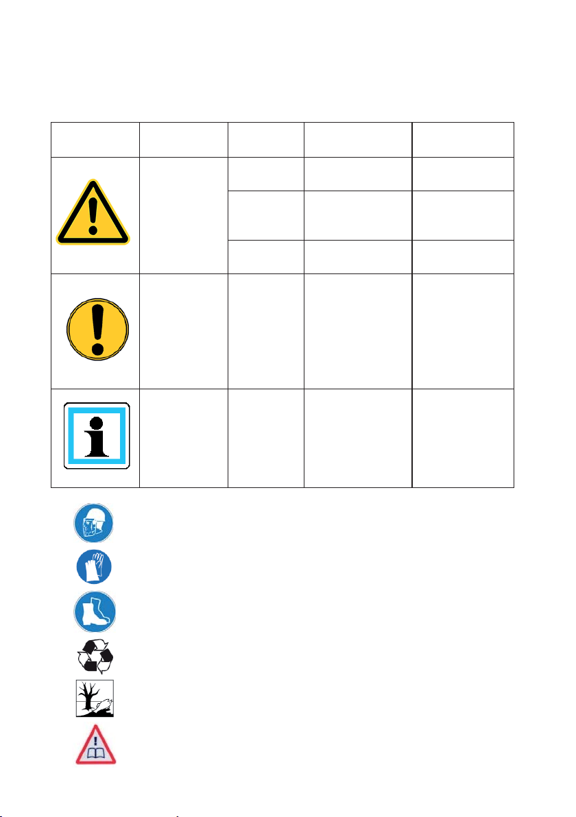
1. Hazard classes
We distinguish between various categories of safety instructions. The table below gives you
an overview of the assignment of symbols (pictograms) and key words to the speci¿ c hazard
and possible consequences.
Pictogram
Wear helmet with face protection
Damage /
injury to
People
Objects
- NOTE
Key word Defi nition Consequences
DANGER! Immediate danger
WARNING!
CAUTION!
ATTENTION!
Potentially
dangerous
situation
Less dangerous
situation
Danger of damage
to objects /
environment
Advice for
application and
other important /
useful information
and advice
Death or major
injury
Potential death or
major injury
Minor or slight
injury
Damage to the
equipment,
damage to the
environment,
damage to
surrounding
materials
No injury /
damage to
persons /
environment /
equipment
Wear safety gloves
Wear safety shoes
Proper recycling
Observe principles of environmental protection
Read and observe operating instructions
5
2. Product safety
LUKAS products are developed and manufactured to ensure the best performance and
quality when used as intended.
The safety of the operator is the most important consideration in the product design.
Moreover, the operating instructions are intended to help the safe use of LUKAS products.
The generally applicable legal and other binding regulations pertaining to the prevention of
accidents and protection of the environment apply and are to be complied with in addition to
the operating instructions.
The device may only be operated by persons with appropriate training in the safety aspects
of such equipment – otherwise, there is a danger of injury occurring.
We would like to point out to all users that they should carefully read and adhere to the
operating instructions before they use the equipment.
We further recommend that a quali¿ ed instructor train you in the use of the product.
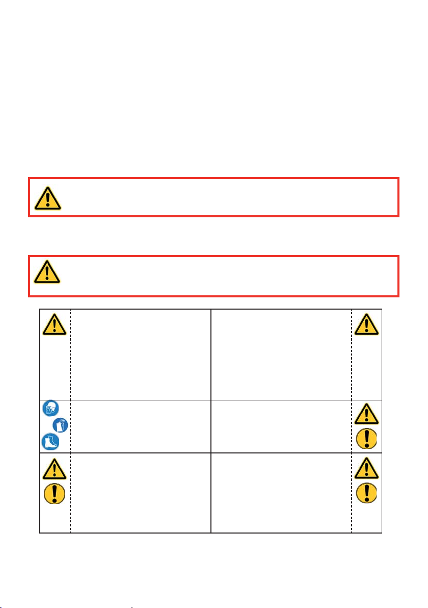
WARNING / CAUTION!
The operating instructions for the hoses, the accessories and the connected
hydraulic equipment must also be observed!
Even if you have already received instructions on how to use the equipment, you should still
read the following safety notes again.
WARNING / CAUTION!
Ensure that the accessories and connected equipment used are suitable for
the maximum operating pressure!
Please ensure that no body
parts or clothing get stuck
between the visibly moving
parts.
Wear protective clothing,
safety helmet with visor, safety
shoes and protective gloves.
It is prohibited to work under
load if this load is lifted
exclusively by hydraulic
equipment. If this work
is absolutely imperative,
additional mechanical supports
must be used.
Immediately report any
changes that occur (including
changes in operating
behaviour) to the appropriate
persons/departments! If
necessary, deactivate the
device immediately and secure
against restart!
Inspect the device for visible
defects or damage before and
after use
Check all lines, hoses and
screwed connections for leaks
and externally visible damage,
and repair immediately!
Escaping hydraulic À uid can
cause injuries and ¿ res.
6
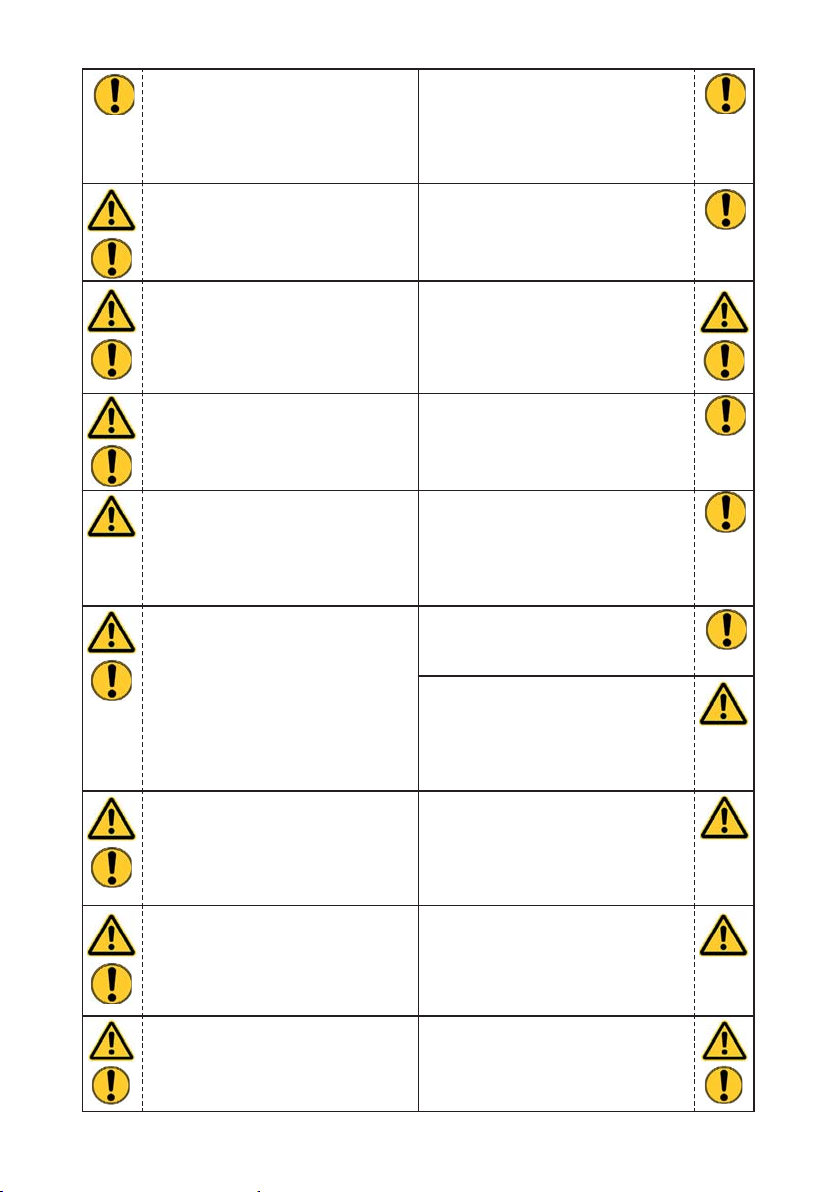
In the event of malfunctions,
immediately shut down the
equipment and secure it.
The malfunction is to be
repaired immediately.
Observe all safety and danger
notes on the device and in the
operating instructions.
Please ensure that all safety
covers are present on the
equipment and that they
are in proper and adequate
condition.
Safety devices must never be
deactivated!
Do not carry out any changes
(additions or conversions)
to the equipment without
obtaining prior approval from
LUKAS.
All safety and danger notes
on the device are to be kept
complete and in a legible
condition.
Any mode of operation which
impairs safety and/or stability
of the device is forbidden!
The maximum operating
pressure set on the equipment
must not be changed!
Before the device is switched
on/started up, and during its
operation, it must be ensured
that nobody is endangered by
the operation of the device.
When working in the proximity
of live components and
wires, appropriate steps must
be taken to avoid current
transmission or high-voltage
discharge through the device.
The build-up of static charge
with the potential consequence
of spark formation is to be
avoided when handling the
device.
Motor pumps may not be used
in explosion hazard areas!
If fuel for combustion engines
is spilled, this fuel must be
removed completely before
starting the motor.
Comply with all speci¿ ed
dates or dates speci¿ ed in
the operating instructions
pertaining to regular checks /
inspections of the equipment.
Only genuine LUKAS
accessories and spare parts
are to be used for repairs.
When working with this
equipment or when
transporting it, ensure that you
do not get caught up in the
hose or cable loops and trip.
When working with
combustion engine pumps,
never touch the motor and
exhaust system, since there is
a risk of burning.
Combustion engines must
not be used in enclosed
spaces, as there is a danger of
poisoning and/or asphyxiation!
Filling up during operation
of the combustion engine is
strictly prohibited!
7
Keep combustion engines and
their fuel away from ignition
sources, as otherwise there is
the danger of an explosion.
All damaged electrical
components e.g. scorched
cables, etc. are to be replaced
immediately!
To avoid the danger of ¿ re
when using combustion
engines, ensure suf¿ cient
ventilation and maintain a
safety distance of at least
1 m (39.4 in.) to the walls and
other screens.
Please ensure that the
combustion engine pumps
are always placed on as À at a
surface as possible in order to
prevent fuel from leaking.
The device is ¿ lled with
hydraulic À uid. These hydraulic
À uids can be harmful to
your health if swallowed or if
their vapours inhaled. Direct
contact with the skin is to be
avoided for the same reason.
Please also note that hydraulic
À uids can also have a negative
effect on biological systems.
Ensure adequate lighting
when you are working.
Always keep these operating
instructions within reach where
the device is used.
Damage to electrical
components may only be
repaired by a quali¿ ed
electrician in compliance with
all applicable national and
international safety guidelines
and regulations.
When setting up the units, it
must be ensured that they are
not impaired by the inÀ uences
of extreme temperatures.
When working with or storing
the device, ensure that the
function and the safety of the
device are not impaired by the
effects of extreme external
temperatures or that the
device is damaged in any way.
Please note that the device
can also heat up over a long
period of use.
Before transporting the
device, always ensure that the
accessories are positioned
such that they cannot cause
an accident.
Ensure the proper disposal of
all removed parts, leftover oil,
hydraulic À uid and packaging
materials.
The generally applicable, legal and other binding national and international regulations
pertaining to the prevention of accidents and protection of the environment apply and are to
be implemented in addition to the operating instructions.
8
WARNING / CAUTION / ATTENTION!
The device is to be used exclusively for the purpose stated in the operating instructions
(see chapter "Intended Use"). Any form of use beyond this is not considered intended
use. The manufacturer / supplier is not liable for any resulting damages. The user bears sole
responsibility for such use.
Observance of the operating instructions and compliance with the inspection and maintenance
conditions are covered by the de¿ nition of intended use.
Never work when you are overtired or intoxicated!
WARNING / CAUTION / ATTENTION!
Should you sustain an injury while working with the hydraulic unit, clean the
wound immediately and seek medical attention!
If hydraulic À uid enters your eye, rinse immediately several times with clear, clean
water and seek medical attention!
You should also seek medical attention after ingesting hydraulic À uid!
9
3. Intended use
LUKAS hydraulic units are specially designed to supply LUKAS rescue equipment with
hydraulic À uid so that this equipment can be used to rescue victims of road, rail or air traf¿ c
accidents as well as from buildings.
Their use for supplying pressure / À uid to rescue equipment of other manufacturers is
possible, yet requires the technical inspection and approval by LUKAS in each individual
case.
The power units were not
(operating time < 15 minutes).
WARNING / CAUTION / ATTENTION!
Always observe the safety notes of these operating instructions with regard to
place of installation and type of installation!
Type P 650 units manufactured by LUKAS are not explosion-proof!
You can obtain accessories and replacement parts for the rescue apparatus from your
authorised LUKAS dealer!
CAUTION!
When selecting a device for connection, remember that the maximum possible
useable volume of the hydraulic À uid is limited.
The maximum total volume of hydraulic À uid required by all connected devices
must not exceed the maximum possible useable volume of the unit!
Due to the limited useable volume, a maximum of 2 rescue rams can be
connected for reasons of safety (only at maximum ¿ ll quantity).
Type R424 cylinders are an exception to the rule, however.
Two of these cylinders should never be coupled and operated
simultaneously!
developed for being operated without hoses or devices
NOTE:
Always register your hydraulic unit on the LUKAS Hydraulik GmbH website.
This is the only way to guarantee your extended warranty cover.
Y ou must always contact LUKAS or an authorised dealer before using couplings
from another manufacturer.
10

4. Labelling of the units
P
Coding for
hydraulic units
650 4 G
Type group
Valve variants
Valve variants:
S = Simultaneous mode
4 = 4POWER mode
Motor variants:
E = Electric motor (operation via mains supply)
G = Gasoline engine
Motor variants
-
ES
with electric starter
-
DHR
Speci¿ cations
(e.g. DHR = with
integral reels)
5. Functional description
5.1 General information
The hydraulic pump on all LUKAS hydraulic units is always operated by a combustion
engine or electric motor. The pump conveys À uid from the reservoir and builds up hydraulic
pressure. The distribution of the À uid is controlled by mounted valves.
Two versions of type P650 unit are available:
1. small frame without reel
2. large frame with mounted reel, Toolholder and carrying handles
The telescopic carrying handles are an optional accessory for the ¿ rst version and can
always be retro¿ tted.
NOTE:
A hose reel is only included with the second version and cannot be retro¿ tted
at a later date!
11
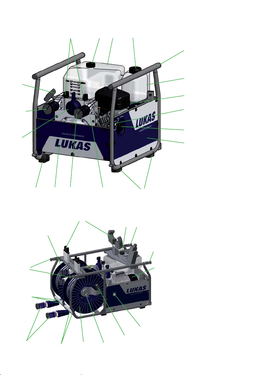
5.2 Structure of the units
8
11 12
1
13
7
10
9
17
10
21
15
18
14
21
10
22
18
4
20
11 17
19
12
15
16
2
3
6
5
14
1 Hydraulic À uid reservoir
2 Gasoline tank
3 Engine with hydraulic
pump
4 Connecting block with
control valves
5 Engine switch
6 Electric starter button
7 Pull cord starter
8 Valve control lever
9 "TURBO" control lever
10 Mono-couplings
1 1 Hydraulic À uid ¿ ll cap
17
12 Gasoline ¿ ll cap
13 Frame
3
14 Side panel
15 Rubber buffer
16 ON/OFF switch for
electric motor
17 T elescopic carrying
handle
(also optionally available
for retro¿ tting)
18 Hose reel
19 Crank handle (hose reel)
20 Lock (hose reel)
21 Hose guide
22 T oolholder

5.3 Motor variants
WARNING / CAUTION / ATTENTION!
For all motor variants, also comply with the separate operating instructions of
each motor manufacturer.
5.3.1 Electric motor
These hydraulic units are equipped with an electric motor. The electric motor is driven by
electricity from the mains supply or by electricity produced by generators. In the case of
operation with generators, make sure that voltage À uctuations do not occur, as these have a
direct inÀ uence on the pumping capacity and stability of the hydraulic unit.
The possible operating voltage, the current frequency and the required intensity of current
can be found in the chapter entitled „Technical data".
NOTE:
Using an extremely long electrical connection cable may reduce the output
resistance and the power supply to the motor. The performance of the motor will
be affected as a result.
5.3.2 Gasoline engine
These hydraulic units are equipped with a combustion engine driven by the fuel "gasoline /
gasoline".
Units can be ¿ tted with both an electric starter and a pull cord starter, or a pull cord starter
only. It is only possible to determine the unit version from the item number and unit name or
the designation printed on the unit.
The integral generator charges the starter battery automatically while the engine is operating.
NOTE:
Not all the technical details of the engine installed in LUKAS units correspond
to the engine described in the separate operating instructions provided by the
manufacturer. Components such as the gasoline tank have been modi¿ ed to
guarantee the safety of the overall hydraulic unit because the unit is used for
rescue operations.
However, it is important that you observe all safety regulations and operating,
maintenance and storage instructions included in the separate manual
accompanying the engine without fail because they are unaffected by any
adaptations made by LUKAS.
If the battery discharges completely after a period of inactivity, you must start the unit using
the cord pull starter and allow the unit to operate until almost a complete tank of fuel has
been consumed. The battery will then be fully charged.
If the battery is still not charged after the unit consumes a full tank of fuel, the causes may
include the following:
- the contacts (connector) have come loose and must be connected again.
- the battery is defective and must be replaced.
- the generator or engine is damaged. In this case, contact LUKAS customer service
directly .
13

5.4 Valve variants
The valves are always permanently installed in a connecting block. This block is integrated
directly in the hydraulic unit. Both hose lines (pressure and return) are always connected to
the connecting block. The units are ¿ tted either with a SIMO or a 4POWER connecting block.
Both connecting blocks also have a TURBO function.
More speci¿ cally, this means that there are always 2 device connections linked internally to
one another. A shift lever gives you the option of supplying hydraulic À uid to both connected
devices simultaneously or supplying double the quantity to one device (= TURBO function).
Supplying double the quantity of À uid increases the operating speed of the connected device.
The hoses and devices are always connected to the connecting block via mono-couplings.
On units with a hose reel, only the connection hoses between the hose reel and connecting
block are screwed in position.
CAUTION!
When operating several pieces of rescue equipment with one unit, ensure that
the usable volume of hydraulic À uid in the reservoir is greater than the maximum
possible operating À uid volume of all connected rescue equipment.
5.4.1 "Simultaneous mode" (SIMO) control valve
This valve enables the connection of two dual-acting hydraulic devices. The valve allows
you to operate two devices simultaneously and independently of one another or supply a
larger quantity of hydraulic À uid to one device. Supplying a larger quantity of hydraulic À uid
increases the operating speed of the relevant device.
There are three switches available. The two smaller switches can be used to depressurise the
individual connections. The large switch is responsible for controlling the TURBO function.
5.4.2 "4POWER mode" control valve
This valve enables the connection of four dual-acting hydraulic devices. The valve allows
you to operate four devices simultaneously and independently of one another or supply a
larger quantity of hydraulic À uid to a maximum of two devices. Supplying a larger quantity of
hydraulic À uid increases the operating speed of the relevant devices. The TURBO function
can only be connected between the points either side of the large switch because the device
connections are linked internally.
There are six switches available. The four smaller switches can be used to depressurise
the individual connections. The large switches are responsible for controlling the TURBO
function.
The switches and connections are labelled to make them easier to assign to one another.
14
5.5 Pumps
LUKAS hydraulic units are equipped with a double-À ow or four-À ow pump depending on the
type. The pumps are permanently connected to the connecting block.
Double-À ow pump for operation with SIMO valve
Four-À ow pump for operation with 4POWER valve
The pumps used are always equipped with two pressure levels for each pump capacity , one
low-pressure and one high-pressure level.
Low-pressure level (LP) = up to 14 MPa*
High-pressure level (HP) = up to 70 MPa*
The changeover from low pressure to high pressure is carried out automatically in the pump.
The maximum pressure is limited by a pressure limiting valve.
WARNING / CAUTION / ATTENTION!
For reasons of safety, the pressure set on this valve must not be adjusted
(without direct authorisation from LUKAS)!
*) 1 MPa = 10 bar
5.6 Frame with side parts
A surrounding frame is ¿ tted to all the hydraulic units described here, without exception.
The frame and the side parts are designed to protect the unit from external inÀ uences (e.g.
dirt, damage, etc.), to attach accessories (e.g. Toolholders) and as a means of transporting
the unit by the frame itself or the optional carrying handles.
The starter equipment and accelerator cable regulator on units with a combustion engine are
mounted on the frame or side parts.
5.7 Connection to the rescue equipment
Connection with the rescue equipment is via extension hose pairs or hose reels. These are
available in various lengths and coloured bend protections.
Different colours distinguish the individual hose lines in a hose pair.
(For specifi c details, please consult the LUKAS range of accessories or contact your
LUKAS dealer).
15
5.8 Hose reels
The hose reels were designed to store extension hose pairs leading between the hydraulic
supply and the working equipment (hose pairs are included in the delivery as standard).
The extension hose pairs are connected to the hose reels and rolled onto the drums.
A hose reel with extension hose pairs can cover long distances between the hydraulic supply
and the working equipment, allowing you to keep the hydraulic unit on a vehicle, for example.
The possibility of rolling up and unrolling the hose allows you to adapt the hose length
accordingly and reduce the amount of unnecessary or potentially dangerous excess hose
lying on the ground.
The extension hose pairs are easier to transport and store when fully rolled up.
Moreover, the hose reels on type P650 units are equipped with a hose guide that facilitates
easier rolling up and unrolling.
The unit is connected to the working equipment via couplings.
CAUTION!
In order to avoid potential losses in pressure, the length of the extension hose
lines must not exceed 30 m!
NOTE:
Only 2 of the 4 connections can be connected to the hose reel on type
P 650 4G units.
There are 2 coupling connections located between the two reel drums for the
remaining two connections. The lower of the two connections is extendable to
allow easier coupling. It also engages easily in the end positions.
The switches and connections are labelled to make them easier to assign to one
another.
5.9 Carrying handle
Type P650 LUKAS hydraulic units without a hose reel can be ¿ tted with optional carrying
handles. The scope of delivery of units with a hose reel already includes handles.
The P650 can be transported more ergonomically using the carrying handles.
5.10 Toolholder
Type P650 LUKAS hydraulic units with a hose reel are ¿ tted with a Toolholder.
The Toolholder is usually designed to attach a spreader and a type S700 cutter.
Needless to say, it is possible to adapt the mount to accommodate all LUKAS cutters and
spreaders as well as modify it at a later date.
The Toolholder allows you to transport a unit with devices still attached.
You no longer have to detach and store devices separately after use. You only have to wind
the hose lines onto the reels and position the devices on the Toolholder again.
Devices secured to the unit do not pose a risk during transport.
16
6. Connection of the hose lines / devices
CAUTION!
When connecting the hose lines / devices, always ensure that the connection
components are not soiled. Clean beforehand if necessary!
WARNING / CAUTION / ATTENTION!
Before connecting equipment, make sure that all the components
used are suitable for the maximum operating pressure of the
hydraulic unit! In cases of doubt, you must consult LUKAS
directly before connecting the equipment!
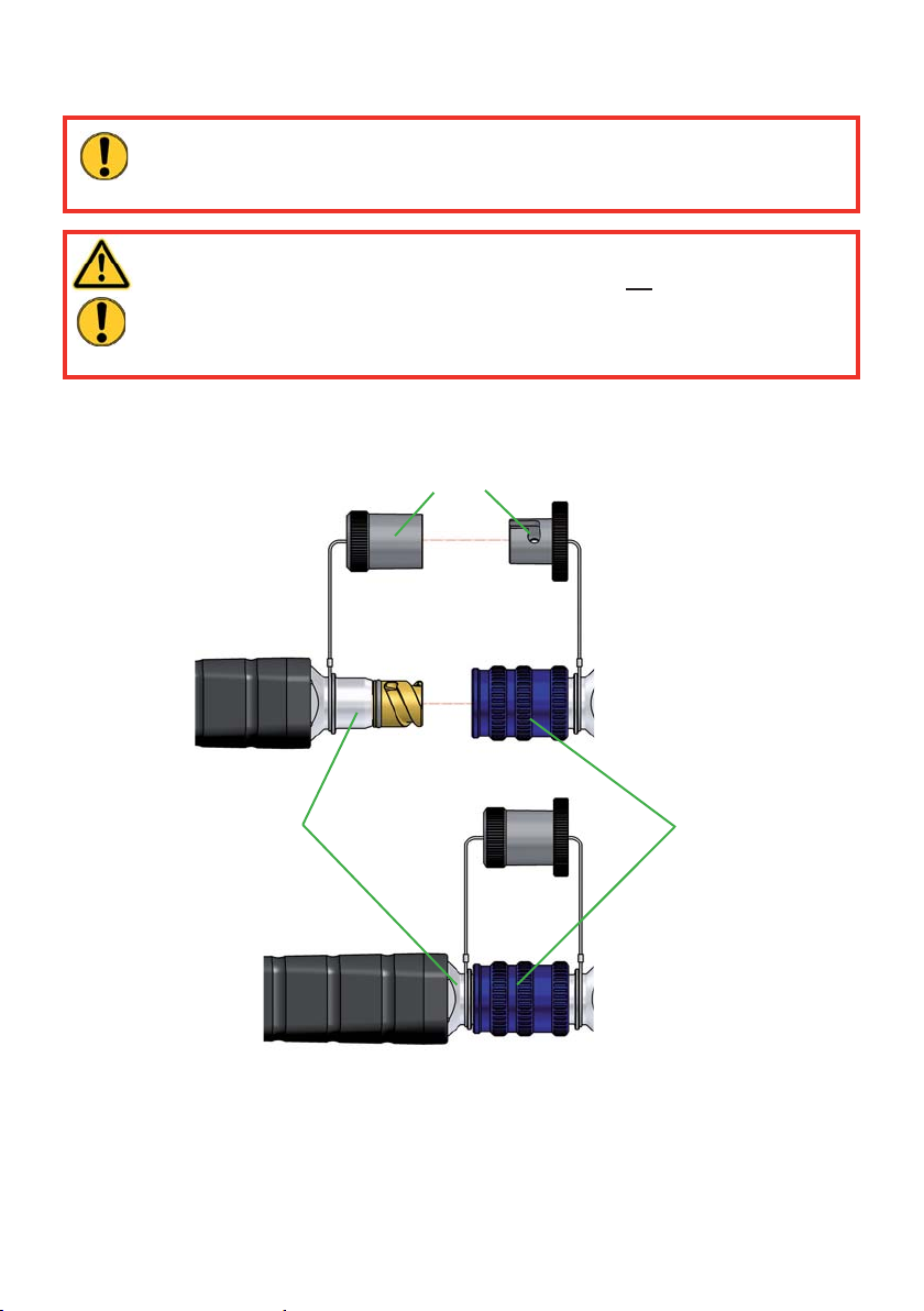
The hose lines / devices are connected to the hydraulic pump or hose reel via mono-coupling
halves (male and female) without any risk of confusion.
Dust protection caps
Male coupling
Female coupling
17
Before coupling, remove the dust protection caps, then connect male and female couplings
and turn the locking sleeve of the female coupling in direction "1" until the locking sleeve
latches. The connection has now been made and locked. Decoupling is accomplished by
turning the locking sleeve in direction "0".
Coupling of the hose lines when under pressure is also possible, assuming the connected
equipment is not turned on.
NOTE:
We recommend connecting the coupling halves in a depressurised state
when working in areas with low ambient temperature and using extension hose
assemblies / hose reels, otherwise the coupling may require the application of a
great deal of force.
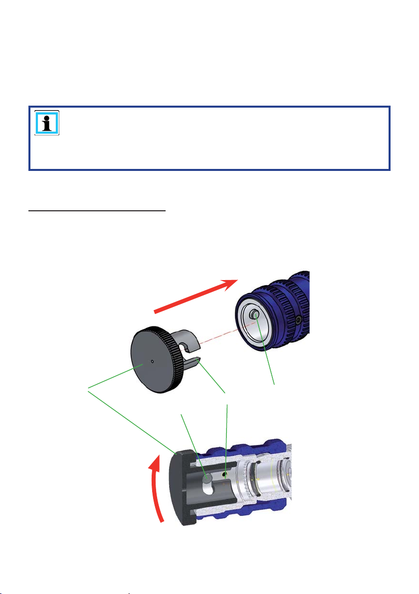
For dust protection, the supplied dust caps must be re¿ tted.
Fitting the dust protection caps:
The "A" dust protection caps have two external grooves "B". The dust protection caps must
be inserted in the female coupling in such a way that the grooves can be guided over the "C"
pins. Screw the dust protection caps to the limit stop to ¿ x in the female couplings.
A
B
C
18
C
7. Set-up and start-up
7.1 Set-up
WARNING / CAUTION / ATTENTION!
Combustion engine units and electrical units must not be used in a potentially
explosive situation (danger of the formation of sparks). Units with combustion
engines must not be used in enclosed spaces, as there is a danger of poisoning
and/or asphyxiation!
The unit is to be set up in a suitable location (safe location / À at surface / suf¿ cient distance
from vehicles, loads, sources of ignition, etc.).
LUKAS units work perfectly at an angle of up to 20°. However, in order to guarantee maximum
safety and À uid withdrawal, they should be operated in as horizontal a position as possible.
7.2 Start-up
NOTE:
Before commissioning the unit for the ¿ rst time or after longer periods of inactivity,
the starter battery must be connected and the engine oil checked (units with a
combustion engine)! Replenish the engine oil if necessary!
LUKAS units are delivered without engine oil for reasons of safety!
Please proceed as follows:
1. First of all, check the À uid levels in the unit.
The translucent reservoirs provide a good view of the À uid levels in the unit. The reservoirs
have marks that indicate the minimum and maximum levels. If possible, the hydraulic unit
should be positioned on a level surface when the À uid levels are read and the reservoirs
¿ lled.
CAUTION!
Always ¿ ll fuel and hydraulic À uid into the correct reservoir otherwise the unit
may sustain damage!
2. On hydraulic units with an electric motor, connect the plug to the power supply at this
point.
3. Then vent the hydraulic unit. Set all levers on the control valves to the neutral position
(see chapter "Operation"). The actual venting is carried out in the units in a different
manner, depending on the drive motor:
a) Gasoline engine:
- Detach all connectors from the sparking plugs (on the back of the unit).
- Slowly turn the engine over with the starter rope several times.
- Then replace the sparking plug connector.
b) Electric motor (mains power operation):
- Switch the motor on and then off again after approx. 10 seconds, repeat
this procedure several times. (Before switching back on,
the motor must be at a standstill!)
19
This procedure means that the pump can slowly draw À uid in and be well vented. The
hydraulic À uid reservoir is equipped with automatic venting, which means no further
venting measures are required.
4. Check the À uid levels in the reservoirs again. If necessary, top up the À uid.
5. To conclude, you can now connect the extension hoses and/or hose reels (unless already
connected to the unit) and/or couple the rescue equipment.
8. Operation
CAUTION!
The control levers on the hydraulic unit must be shifted to neutral position before
the motor/engine is started to prevent connected hydraulic equipment from
moving unexpectedly.
Levers on units with a Toolholder should only be shifted back after you have
removed the devices from the mount and intend to start work.
8.1 Starting the motor/engine
8.1.1 Gasoline engines
Before starting the combustion engines, check that the fuel tank is full and that the engine oil
level is within the permitted tolerances. If necessary, top up the relevant À uid.
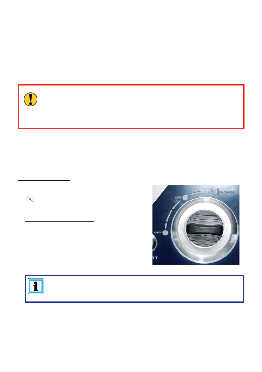
Starting procedure:
1. Set the engine switch to the "CHOKE" position
( ) (if the engine is already warm or the ambient
temperature is high, start the engine with the
switch in the "ON" position.)
2. Starting with electric starter:
Press the starter button
Starting with pull cord starter:
Slowly pull the handle on the pull cord starter
beyond the compression point (resistance is felt).
Allow to return to the starting position and pull
again quickly all the way out.
NOTE:
If the engine refuses to start after several attempts, repeat the procedure
described above with the engine switch set to the "ON" position.
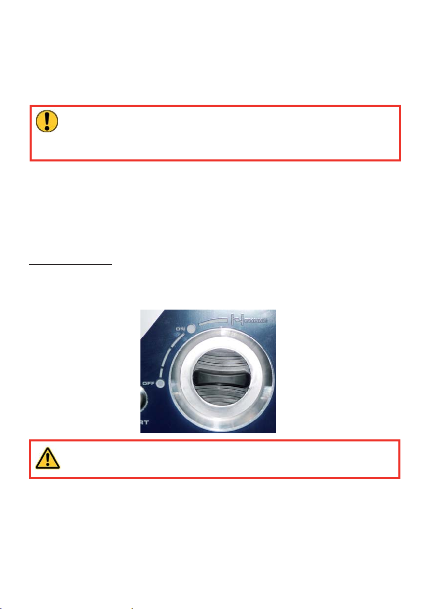
3. When the engine starts, keep hold of the handle on the pull cord starter and allow it to
return to its starting position.
4. Allow the engine to warm up for 20 to 30 seconds and then set the engine switch to the
"ON" position (if previously set to "CHOKE").
20
8.1.2 Electric motors
Before starting the electric motors, check that all electrical connections and cables are in
proper order. First of all, connect the power cable (for motors with power supply) to the
supply socket.
The motor is started by pressing the ON/OFF switch on the side of the unit. The ring around
the switch lights up when the unit is switched on.
CAUTION!
Electric motors draw a brief, very high starting current. When using a generator,
you should therefore check to see that it can supply the relevant current strength.
The power supply must be protected by a 25 A fuse at least.
8.2 Stopping the motor/engine
8.2.1 Gasoline engines
The engine on the unit stops automatically when the fuel tank is empty. However, you should
stop the machine and refuel before this happens.
The following procedure stops the engine manually:
Stopping procedure:
1. Make sure that all connected rescue devices are in base position (starting position).
2. Set the levers on the control valves to neutral position (depressurised).
3. Set the engine switch to the "OFF" position.
WARNING / CAUTION!
Never touch the hot motor / engine parts: this could result in severe burns!
8.2.2 Electric motors
Set the levers on the control valves to neutral position (depressurised).
Pressing the ON/OFF switch on the side of the unit switches the engine off again. The illuminated
ring around the switch goes out.
When the engine is switched off, the connected hydraulic pump stops delivering.
21

8.3 Refuelling (combustion engines only)
The engine must be switched off during refuelling!
Procedure:
1. Open the ¿ ll cap on the fuel tank.
2. Fill the tank with fuel up to the maximum mark.
WARNING / CAUTION / ATTENTION!
Make sure you do not spill any fuel! If fuel comes into contact with hot engine
components, in particular, there is a risk it may ignite and start a ¿ re!
If fuel is spilled by accident, it must be cleaned up immediately using a
suitable absorbent cloth. Make sure you do not burn yourself on hot engine
components! The cloth used to absorb the spilled fuel must then be washed
and disposed of according to applicable regulations and guidelines!
3. Replace the ¿ ll cap on the fuel tank again correctly.
8.4 Controlling the valves
CAUTION!
The control levers on the hydraulic unit must be shifted to neutral position
(depressurised) before the motor/engine is started to prevent connected
hydraulic equipment from moving unexpectedly.
8.4.1 "Simultaneous mode" (SIMO) control valve
Three levers are located on the connecting block of this valve.
Each of the two small levers is assigned to a pressure port. Actuating
the respective lever regulates the pressure in the corresponding pressure
hose (" ") or depressurises the connection (" ").
There is also a large lever that controls the "TURBO"
function. Shifting the lever to the relevant position allows you
to supply double the quantity of hydraulic À uid to one of the
two connections.
In order to activate the "TURBO" function, both connections
must be pressurised. The "TURBO" function is activated by
turning the large lever towards the connection that requires
double the À uid quantity.
22

NOTE:
All shift levers must always be moved all the way to their end position.
8.4.2 "4POWER mode" control valve
Six levers are located on the connecting block of this valve.
Each of the four small levers is assigned to a pressure port. Actuating
the respective lever regulates the pressure in the corresponding pressure
hose (" ") or depressurises the connection (" ").
There are also two large levers that control the "TURBO"
function. Shifting the lever to the relevant position allows you
to supply double the quantity of hydraulic À uid to one of the
two connections either side of the lever.
In order to activate the "TURBO" function, both connections
must be pressurised. The "TURBO" function is activated by
turning the large lever towards the connection that requires
double the À uid quantity.
NOTE:
All shift levers must always be moved all the way to their end position.
23

8.5 Hose reels
8.5.1 Locking brake
The locking brake is designed to prevent extension hose pairs from unrolling during
transportation! Pull and turn knob through 90° to release the locking brake.
To apply the locking brake, turn knob through approx. 90° until it engages automatically.
90°
90°
8.5.2 Crank handle
The crank handle should make the hose easier to roll up!
T o use the crank handle, pull lever, fold outwards through 90° and release so that it engages.
To fold away the crank handle, pull lever fold inwards through 90° and release so that it
engages.
8.5.3 Unrolling
Pull the extension hose pair until the required length has unrolled from the hose reel.
CAUTION!
Release the locking brake on the hose reel beforehand to avoid damaging the
reel and the pair of hoses!
24

8.5.4 Rolling up
NOTE:
We recommend using the crank handle to roll up the hoses!
- Fold out the crank handle.
- Check that the locking brake on the double hose reels is released.
- Align the reels so that the unrolled hoses are rolled up in a straight line. You will ¿ nd that
the hoses roll up more easily.
- You can now roll up the pair of extension hoses by turning the crank handle.
Make sure that the direction of rotation is always the same as shown in the illustration!
Elbow piece
Make sure that the pair of extension hoses is always rolled up correctly onto the hose
drum.
We recommend guiding the pair of extension hoses with your hand during the rolling
process. You must always guide the pair of hoses in a perpendicular direction to the reel
axis because of the hose guide attached to the hose reel.
- You must then apply the locking brake on the double hose reels.
CAUTION!
The bend protection on the hoses should only rest lightly on the hose guide
when the hose is rolled up completely.
However, if the hose line is rolled up so far that the bend protection is pressed up
against the hose guide, the following could occur:
- The hose material is stretched and the hose damaged, possibly beyond
repair.
- The couplings, bend protection and hoses may be damaged during
transportation or storage.
Direction of rotation
"Rolling up"
Hose
25

8.6 Telescopic carrying handles
Units with a hose reel are ¿ tted with carrying handles. Units without a hose reel can be
retro¿ tted with handles if required. The handles should be used to transport the P650.
The telescopic carrying handles are screwed directly to the frame. The blanking plugs must
be removed before the handles can be attached.
Turn the handles clockwise (approx. 1 revolution) in the end positions (retracted or extended
completely) to secure them properly. Turn the handles anticlockwise (approx. 1 revolution)
to unlock them.
Always fully extend and secure the carrying handles before using them to transport the unit.
When not in use, always insert and secure the carrying handles to prevent them from
restricting your movement when operating the unit. The handles should also be inserted and
secured when stored to reduce the risk of accident.
Procedure (fi tting the telescopic carrying handles to units without a reel):
1. Remove protective covers "A" using a screwdriver.
A
2. Insert telescopic carrying handle "B" in the frame and screw in guide sleeve "C".
C
3. Then slide the telescopic carrying handle all the way in and lock in position.
B
26

8.7 Toolholder
A device must ¿ rst be detached from retaining
clip before it can be removed from the
toolholder.
The device is then easy to remove.
The device is ¿ tted in the reverse order.
Make sure that the handle tube on the rescue
equipment engages properly in the retaining
clip.
Remove a spreader:
0
1
2
3
27

Procedure (fi tting and adjusting the Toolholder):
NOTE:
If you wish to install a Toolholder at a later time or adapt an existing mount to a
new device, follow the working steps described below.
1. Mount the retaining clip "A" on block "C" and
secure using the screws "B".
2. Secure the two brackets "D" and "E" to mounting plate "G" using screws "F".
A
B
Using cutter models S700, it must be proceeded as
follows with the retainer. Because of the size of the
cutters the bracket "J" must be installed on mounting
block "R" using screws "O". Mounting block "R" is
then secured to mounting plate "K" using screws "S".
D
C
G
O
R
E
K
Position for S 700
J
R
S
K
28
F
G

3. Then mount bracket "H" for the spreader and combi tool as well as bracket "J" for
the cutters to mounting plate "K" (see illustration below). The brackets are secured in
position using screws "L", "M", "N" and "O" as well as washers "P" and nuts "Q".
H
L
O
N
M
S 5xx
J
Using cutter models S 5xx and S 3xx, it must
be proceeded with the retainer as in the
illustrations and in each case a rubber spacer
must be screwed into the mount bracket.
V
N
K
Position for S 5xx
Q
P
P
Q
S 3xx
J
Position for S 3xx
29

4. Mounting plates "G" and "K" are secured to the frame of the unit using screws "T"
as shown in the illustration below.
G
T
K
T
T
30
T

5. Now adapt the brackets to the respective devices. Loosen the ¿ xing screws "F" and "S"
or nuts "Q" slightly so that the brackets are easy to move. Do not unscrew the screws or
nuts completely.
The elongated holes "U" in the mounting plates allow you to adapt the brackets to almost
every device or individual position of your choice.
Next tighten all loose ¿ xing screws or nuts to secure the bracket in the selected position.
U
6. The mount is dismantled in reverse order.
31

9. Removing the device / deactivation following operation
Once work has been completed, all connected equipment is to be reset to its base position
before the unit is shut down. You can now stop or switch off the motor/engine on the unit and
disconnect it from the mains supply, if using an electric motor.
ATTENTION when using units with a combustion engine!
Check that the engine switch is set to "OFF" and remains in that position to
prevent anyone from starting the unit unintentionally!
NOTE:
If your unit is equipped with a hose reel, the hoses must be rolled onto the reels
correctly!
Mono-couplings:
If the connected hose lines have to be dismantled during shut-down, decouple the monocouplings as described in chapter "Connection of the hose lines". Ensure that you replace
the dust protection caps onto the mono-coupling halves.
Give the hydraulic unit a general clean before placing in storage. If you intend to store
the unit for longer, clean the outside thoroughly and lubricate all mechanical moving parts.
CAUTION!
Depending on the size and the weight of the hydraulic unit, it should be transported
to the storage site by one person or several people.
On units with a combustion engine, you should drain the fuel from the tank and disconnect
and/or remove the starter battery.
Avoid storing the hydraulic units in a damp environment.
Please observe the regulations in the separate operating instructions for the hose lines.
32

10. T ests
The hydraulic units are subject to very high mechanical loads. A visual inspection is therefore
to be carried out after every use, however at least one visual inspection is to be carried out
every six months.
This reveals wear and tear in good time; punctual replacement of these wearing parts
prevents damage to the equipment. Also check regularly that all the securing screws are
tightened (if applicable, comply with prescribed tightening torques)
Every 3 years or when there might be doubts regarding the safety or reliability of the unit, an
additional functional check is to be carried out (in this connection, comply with the applicable
national and international regulations with regard to the maintenance intervals of rescue
equipment). In the Federal Republic of Germany , regular safety inspections according to the
regulations of the Gesetzliche Unfallversicherung (GUV; 'statutory accident insurance') are
mandatory .
CAUTION!
Clean off any dirt before checking the equipment!
WARNING / CAUTION / ATTENTION!
In order to carry out testing, maintenance and repair work, tools appropriate for
the job and personal protecting equipment are essential. (use protective shields
if required).
LUKAS offers a suitable test kit for the functional check of the hydraulic units.
(For specifi c details, please consult the LUKAS range of accessories or contact your
LUKAS dealer).
10.1 Recommended inspection intervals
10.1.1 Visual inspection
A visual inspection is to be carried out after every use or every six months.
33

10.1.2 Functional check
Operating period per day Functional check
up to 1 hour 1 x every year
up to 8 hours 1 x per quarter
up to 24 hours 1 x per month
A functional check should be performed in addition to these intervals if:
- the unit makes suspicious noises,
- there are grounds for suspecting that the unit has sustained internal damage.
Should either of the above occur several times within a month or the maximum pressure
is not reached during the functional check, contact LUKAS customer service immediately.
See the chapter "Troubleshooting" for contact details.
10.2 Hydraulic units with combustion engine
Visual inspection
Hydraulic units
• All hydraulic connections are still tightened
• General tightness, no leakage (sweated oils do not have any inÀ uence on the function)
• Obvious damage on the motor/engine, connecting blocks or frame
• Obvious damage to the hydraulic system and/or gasoline tank,
• Side panels present and securely ¿ tted
• Type plate, all activation plates, signs, identi¿ cation marks and warning labels are present
and legible
• All covers (e.g. exhaust deÀ ector) are present and undamaged
• All heat protection mats on the reservoirs are present and undamaged,
• Minimum gap of 10 mm between the reservoirs and hot motor/engine components
• Liquid levels are within the speci¿ ed tolerances
• Starters are in proper working order and undamaged
• Electric cables are fully functional and undamaged
• Electric starter battery is fully functional and undamaged
• Couplings must be easy to couple
• Dust protection caps must be available
• All necessary accessories (such as sparking plugs, plug spanner and fuel canister) must
be present.
• Toolholder (if available) is undamaged and fully functional
• Carrying handles (if available) are undamaged and fully functional
34

Functional check
• No suspicious noises
• Starter fully functional
• Engine switch fully functional
• Test for maximum load
(Recommendation: use the LUKAS test kit, including testing instructions, for the functional
check).
10.3 Hydraulic units with electric motor
Visual inspection
Hydraulic units
• All hydraulic connections are tightened
• General tightness, no leakage (sweated oils do not have any inÀ uence on the function)
• Obvious damage to the motor/engine, valve blocks or casing
• Side panels present and securely ¿ tted
• Type plate, all activation plates, signs, identi¿ cation marks and warning labels are present
and legible
• All covers (e.g. fan cover) are present and undamaged
• Liquid levels are within the speci¿ ed tolerances
• ON/OFF switch in proper working order, undamaged
• Couplings must be easy to couple
• Dust protection caps must be available
• All electrical attachments (such as cables and plugs) must be present and undamaged
• Toolholder (if available) is undamaged and fully functional
• Carrying handles (if available) are undamaged and fully functional
Functional check
• No suspicious noises
• Test for maximum load
(Recommendation: use the LUKAS test kit, including testing instructions, for the functional
check).
35

10.4 Hose reels
Visual inspection
Hose reel
• General tightness (no leaks)
• Hose drums rotate easily
• All ¿ xing screws are present and tightened
• Frame and drum undamaged
• Crank handle present, undamaged and fully functional
• Locking brake on double hose reel present and fully functional
• All signs present and legible
Hoses
• Visual inspection for visible damage and leaks
• Check age of hose (replace after 10 years at the latest)
• Hose connection on mounted reel secure and not leaking
• Couplings must be easy to couple
• Dust caps ¿ tted
Functional check
• Extension hose pairs unroll and roll up smoothly.
• No suspicious noises
11. Maintenance and repair
11.1 General information
LUKAS type P 650 hydraulic units have an extremely complex design but require minimal
maintenance work. Maintenance work does not require special training, but knowledge
on operating the unit, statutory safety regulations and handling all the necessary tools are
basic requirements.
CAUTION!
Do not exert excess force when performing maintenance work on the unit as this
may damage components or compromise the operational safety of the unit
Due to the complex design, repair work on the actual hydraulic unit must always
be performed by the equipment manufacturer, personnel trained by the equipment
manufacturer or authorised LUKAS dealers.
WARNING / CAUTION / ATTENTION!
During maintenance and repair work, it is essential to wear protective clothing
since equipment can still be pressurised even when it is not in operation.
During the work, ensure that all components are particularly clean, since dirt
can damage the unit!
36

CAUTION!
Since LUKAS hydraulic units are designed for top performance, only those
components in the spare parts lists of the relevant unit may be replaced.
Further components in the unit may only be replaced if:
- you have taken part in appropriate LUKAS service training,
- you have the express permission of LUKAS Customer Service (after request,
veri¿ cation that permission may be granted. Veri¿ cation required in each
individual case!)
When cleaning units and equipment, note that no cleaning agent may be used
that has a pH value outside the range 5 - 8!
CAUTION!
Attention must be paid to ensuring that no operating À uids can escape from
units with combustion engines during repair work!
11.2 Maintenance work on the hydraulic unit
11.2.1 Cleaning instructions
The outside of the device must be cleaned from time to time (not the electrical contacts)
and the metallic surfaces (not the electrical contacts) treated with a suitable agent to
protect against corrosion.
(In case of doubt, contact your authorised LUKAS dealer or LUKAS directly!)
11.2.2 Function and load test
If there is any doubt regarding the safety or reliability of the equipment, a function and load
test must also be performed.
LUKAS offers appropriate test equipment.
11.2.3 Replacing the hydraulic fl uid
- After approx. 200 deployments, but after three years at the latest, replace the hydraulic
À uid
- The À uid should be replaced when it is warmed up.
- The motor must be switched off!
- The old hydraulic À uid must be disposed of properly.
37

Procedure:
1. Place the unit on a slightly raised base so that the drain screw for the hydraulic À uid is
easy to access.
2. Place a suitable container under drain screw "A".
3. Open ¿ ll cap "B", remove drain screw "A" and seal ring "C", and allow the hydraulic À uid
to drain into the container provided.
B
C
A
4. Re¿ t components "A" and "C" in the reverse order.
5. Fill fresh hydraulic À uid into the reservoir through the ¿ ller neck and then close off the
neck with ¿ ll cap "B".
6. Finally, the unit must be vented as described in the chapter entitled "Start-up".
11.2.4 Replacing signs
All damaged and/or illegible signs (safety notices, type plate etc.) must be replaced.
Procedure:
1. Remove damaged and/or illegible labels.
2. Clean surfaces with industrial alcohol.
3. Af¿ x new signs.
Ensure that you attach the signs in the correct position. If this is no longer known, you should
ask your authorised LUKAS dealer or contact LUKAS directly.
38

11.3 Additional maintenance work on units with a combustion
engine
(also read the separate instructions provided by the engine/motor manufacturer)
Perform the following maintenance work every 50 operating hours:
• Wash the air ¿ lter element. Wash more frequently when using the unit in a dirty or dusty
environment.
• Check the sparking plug and clean if necessary
Perform the following maintenance work every 100 operating hours:
• Change the engine oil. Change more frequently when operating the unit in a dirty or
dusty environment.
Perform the following maintenance work every 200 operating hours:
• Adjust the electrode gap on the sparking plug
• Clean the fuel ¿ lter
Perform the following maintenance work every 500 operating hours:
• Replace the sparking plug and ¿ lter element
• Clean or adjust the carburettor, valve clearance, valve seat and cylinder head.
Perform the following maintenance work every 1000 operating hours or every 2 years:
• Check the starter
• Inspect the engine/motor for damage
• Replace the fuel line.
NOTE:
The ¿ rst oil change must take place after 20 operating hours and the next oil
change after 100 hours.
Use a standard articulated sparking plug socket spanner (21 mm) to remove the
sparking plug.
A straight / ¿ xed sparking plug socket would damage or break off the sparking
plug!
39

11.3.1 Changing and cleaning the air fi lter
Maintaining the air ¿ lter in good condition is essential.
The ingress of dirt due to incorrect installation, incorrect maintenance or unsuitable ¿ lter
inserts causes damage and excess wear to the engine/motor. Always keep the air ¿ lter insert
clean.
Procedure:
1. Remove the rear side panel on the hydraulic unit by detaching the mounting clips.
2. Unhook the cover and remove the ¿ lter insert.
3. Paper insert:
To clean, tap gently to loosen the dirt and then blow off the dust. Never use oil! Clean the
paper insert every 50 operating hours and replace every 200 hours or once a year.
4. Urethane foam:
Wash out the insert with fresh water. Squeeze out the water and dry the insert. (DO NOT
WRING OUT!!)
5. Then re¿ t the ¿ lter.
Air ¿ lter
40

11.3.2 Changing, cleaning and adjusting the sparking plug
Procedure:
1. Remove the right side panel on the hydraulic unit by detaching the mounting clips.
2. Remove the sparking plug connector. The connector is attached ¿ rmly and may require
greater effort to remove. During removal, make sure you do not bend the connector or
exert lateral force on the sparking plug. In a worst case scenario, you will destroy the
sparking plug and will then have to carry out expensive repairs.
Sparking plug
connector
3. Remove the sparking plug from the engine using a 21 mm articulated sparking plug socket
for sparking plugs.
4. Remove any soot on the sparking plug using a sparking plug cleaning agent or a brush.
If the sparking plug is damaged beyond repair (e.g. electrodes burnt), it must be replaced
with a new one.
5. Set the gap between the electrodes to 0.6 - 0.7 mm.
Sparking plug
0.6 - 0.7 mm
6. Then re¿ t the sparking plug.
11.3.3 Changing the engine oil and engine fi lter
Please refer to the separate operating instructions provided by the engine manufacturer for
information on changing the engine oil and the engine ¿ lter.
41

11.3.4 Externally charging and replacing the starter battery
Procedure:
1. Remove the left side panel "A" on the hydraulic unit by detaching the mounting clips "B".
2. Starter battery "C" is now visible. First disconnect the negative ("-") and then the positive
terminal ("+") on the battery.
A
B
3. If you would like to charge the starter battery
using an external charger, connect the
device now. (Read the instruction manual
accompanying the charger)
If the battery is defective, it must be replaced.
Loosen attachment belt "D" and remove the
battery . When replacing the battery, make sure
that you insert the new battery as shown in the
illustration.
The unit is assembled in reverse order.
CD
42

11.4 Maintenance work on mounted hose reel
A visual inspection of the ¿ tted hoses and couplings is to be carried out after every use
or every six months. Components showing obvious signs of damage or leaks must be
replaced. If screwed connections start to leak, check whether they are tight ¿ rst of all. If the
leak continues after the screwed connection has been tightened, the screwed connection is
defective and must be replaced.
Hose lines will age over time and must be replaced according to statutory regulations.
If there are no applicable statutory regulations, the hoses must be replaced after 10 years
at the latest. (Read the separate operating instructions for the hoses.)
11.4.1 Replacing the extension hose lines
Procedure:
C
1. First of all, empty the hydraulic reservoir
as described in the chapter "Replacing the
hydraulic À uid".
2. Unroll extension hoses "A". Slide protective
hoses "B" over elbow piece "C", leaving
the screwed connection uncovered.
Then unscrew the hoses.
43
A
B

3. Screw the new extension hoses onto the elbow
pieces with a torque of
M
= 40 Nm. Do not forget to slide protective hoses
A
"B" back over the screwed connections.
The protective hose set must be
fi tted to the reel!
4. Roll up the extension hose again.
5. The hydraulic À uid reservoir must then be ¿ lled and the unit vented.
11.4.2 Mono-couplings
The mono-couplings must be replaced if:
- there is external damage,
- the lock does not function correctly,
- hydraulic À uid continues to leak in a coupled/uncoupled state.
B
WARNING / CAUTION / ATTENTION!
Never repair couplings: they must be replaced with genuine LUKAS parts!
Procedure for couplings on the valve block:
1. First of all, empty the hydraulic reservoir as described in the chapter "Replacing the
hydraulic À uid".
2. Remove the screwed connections on the coupling.
3. Remove the couplings and seals underneath
4. Place the new coupling on the valve block together with the seals.
5.
Secure the couplings again using the screws and tighten these to a torque of MA = 40 Nm.
6. The hydraulic À uid reservoir must then be ¿ lled and the unit vented.
44

Procedure for couplings on hose pairs:
1. First of all, empty the hydraulic reservoir as described in the chapter "Replacing the
hydraulic À uid".
2. Pull the cover back from the couplings.
3. Loosen the union nuts on the hose lines and remove the coupling.
CAUTION!
As the case may be, make sure that port 'T' / 'T1' of the hose reel is always
connected to port 'T' of the mono-coupling.
4. Position the new coupling and tighten the union nuts on the hose lines to a torque of
M
= 40 Nm and push the cover back over the couplings.
A
5. The hydraulic À uid reservoir must then be ¿ lled and the unit vented.
45

12. T roubleshooting
In the case of defects which directly affect the motor / engine, please consult the separate
operating instructions of the motor / engine manufacturer.
Trouble Check Cause Solution
Electric motor
does not operate
when the switch is
actuated or does
not operate at full
power
Check the
connection cable
on the electric
motor
Extension cable
or cable drum
used?
Electric motor
connected
to a suitable
accumulator?
Electric safety
device in power
supply has
triggered
Are all valves
depressurised
(base position)?
Power cable not
connected
Defect on connection
cable
Cable not completely
uncoiled
Cable losses in
extension cable or
cable drums too great
(electrical resistance)
Battery À at Charge battery
Electric motor
not suitable for
accumulator operation
Power supply not
suitable for electric
motor
Electric safety device
in power supply has
triggered although it is
suitable for operation
of the motor.
Electric motor
defective or
overloaded due to
another defect in the
unit
Connect power cable
correctly
Shut down immediately
and have repaired by
authorised dealer, motor
/ engine manufacturer or
directly by LUKAS
Uncoil the power cable
completely
Use a different suitable
extension cable or cable
drum.
Connect the motor to a
different suitable power
supply
Connect the motor to a
different suitable power
supply
Safety device too low,
use a different fuse.
Shut down immediately
and have repaired by
authorised dealer, motor
/ engine manufacturer or
directly by LUKAS
46

Trouble Check Cause Solution
Combustion
engine will not
start
Check fuel level
in tank
Electric starter
present?
Check fuel line Fault in the fuel line Shut down immediately
Check the starter
button and
engine switch
Hydraulic unit or
motor / engine
not suitable
for the working
environment
Check air ¿ lter Air ¿ lter contaminated Clean or replace the air
Are all valves
depressurised
(base position)?
Fuel tank empty Top up fuel
Electric starter battery
À at
Starter button or pull
cord starter not
actuated
Engine switch not set
to “Choke”
Ambient temperature
too low
Not enough oxygen in
the air because of the
altitude of application
location of the
hydraulic motor
Combustion
engine defective or
overloaded due to
another defect in the
unit
Charge electric starter
battery or use pull cord
starter
and have repaired by
authorised dealer, motor
/ engine manufacturer or
directly by LUKAS
Actuate starter button or
pull cord starter
Set engine switch to
“Choke”
For the solution,
consult the separate
operating instructions
of the engine / motor
manufacturer.
Use a different hydraulic
or operating À uid that
is suitable for the
corresponding ambient
temperatures (see
chapter “Technical data”)
Use a different more
suitable hydraulic unit.
Have the engine set to
the altitude of application
by an authorised
dealer, motor / engine
manufacturer or LUKAS
directly (only if the unit is
to be used frequently at
this altitude).
¿ lter.
Have repaired by
authorised dealer, motor
/ engine manufacturer or
directly by LUKAS
47

Trouble Check Cause Solution
The motor / engine
is running, but
the connected
rescue equipment
does not move
when the valve is
actuated.
The connected
rescue equipment
does not move on
activation of the
valve, or moves
only very slowly or
unevenly.
Check hose line Hose line not
connected properly or
is damaged
Check the
position of the
valve lever on the
pump block of the
hydraulic unit
Connect another
device and
check whether it
functions when
the valve is
actuated
Connect another
device and
check whether it
functions when
the valve is
actuated
Check the
position of the
valve lever on the
pump block of the
hydraulic unit
Valve not switched to
pressurise the supply
line.
Defective pump unit Have repaired by
The previously
connected device is
defective.
Mono-coupling
(female) defective
The previously
connected device is
defective.
Pressure relief on
the unit is still active
(circulation at static
pressure)
Defective pump unit Have repaired by
Air in hydraulic system Vent the hydraulic
Mono-coupling
(female) defective
Inspect the connection
of the hose line and,
if necessary, reconnect
Switch valve to
pressurise the supply
line.
authorised dealer or
directly by LUKAS
For the solution,
consult the operating
instructions for the
connected device
Replace mono-coupling
(female)
For the solution,
consult the operating
instructions for the
connected device
Check the switching
positions of the
valve lever(s) and,
if necessary, reset
(as far as the ¿ nal
position)
authorised dealer or
directly by LUKAS
system
Replace mono-coupling
(female)
48

Trouble Check Cause Solution
Connected rescue
device does not
reach its ¿ nal
position
Connected rescue
device does not
reach its speci¿ c
performance data
During the
functional check:
A pressure gauge
installed between
the rescue
equipment and
the hydraulic
power pack does
not indicate
the maximum
operating pressure
of the equipment.
Check hydraulic
À uid volume
in hydraulic
reservoir
Check the details
of the rescue
device
Insuf¿ cient À uid in the
hydraulic reservoir
Usable hydraulic À uid
volume of the unit is
insuf¿ cient
Maximum permitted
operating pressure
of the pump is not
reached
Defective pump block Have repaired by
Connected device is
defective
The operating pressure
of the connected
rescue device is
locked internally
Connected rescue
device is defective
Hydraulic unit
defective
Top up hydraulic À uid to
the maximum ¿ lling level
Caution! Before
topping up the rescue
equipment, return to
the base position!
Use a different rescue
device with a required
quantity below the
maximum usable
quantity of the unit
Have the pressure
limiting valve reset or
repaired by authorised
dealer or directly by
LUKAS
authorised dealer or
directly by LUKAS
For the solution,
consult the operating
instructions for the
connected device
No repair or fault
recti¿ cation required
Consult the separate
operating manual for
the connected rescue
device
Have repaired by
authorised dealer or
directly by LUKAS
49

Trouble Check Cause Solution
Fluid escaping
from the hydraulic
À uid reservoir
Leaking À uid
between engine
and À ange bearing
Hydraulic À uid
milky and cloudy
Hose line cannot
be coupled
Impossible to
retract or extend
carrying handles.
Impossible to lock
or unlock carrying
handles
Hose reel does
not turn
Impossible to
attach equipment
to the Toolholder
Connected
device is not yet
in base position
and À uid is
escaping from the
¿ ller screw?
Fluid leaking from
a different place?
Return of the hydraulic
À uid from the rescue
device exceeds the
reservoir’s maximum
quantity when ¿ lled.
Leak on reservoir,
lines or seals
Radial shaft seal
on the drive shaft is
defective
Water / condensation
in the system
Pressure too high (e.g.
caused by excessive
ambient temperature)
Coupling defective Coupling must be
Carrying handles are
still locked
Carrying handles or
frame defective
Carrying handles or
frame defective
Locking brake still
applied
Hose reel defective Have repaired by
Toolholder set
incorrectly
Toolholder defective Replace Toolholder.
Reduce the ¿ ll level
in the hydraulic
À uid reservoir to the
"minimum" mark, move
the device to base
position and then ¿ ll
the À uid back up to
"maximum"
Replace defective
components or have
repaired by authorised
dealer or directly by
LUKAS
Have repaired by
authorised dealer or
directly by LUKAS
Immediately replace
hydraulic À uid
Switch valve block to
circulation at static
pressure
replaced immediately
Unlock carrying handles
and extend.
Replace the carrying
handles or frame.
Replace the carrying
handles or frame.
Release locking brake
authorised dealer or
directly by LUKAS
Adjust the Toolholder
to accommodate the
device.
50

Trouble Check Cause Solution
It is frequently not
possible to couple
hose lines
Leak in the
couplings
Fluid escaping
from hoses or
joints
Surface of the
hoses damaged
Hydraulic À uid
escaping from
inside the hose
drum.
Hydraulic À uid
escaping from
the connections
between the
connection hoses
and reel shaft
Connection
between hub and
shaft leaking
Extension hose
pairs damaged?
Screwed
connection on the
hose lines tight?
Screwed
connection
between elbow
piece and shaft
leaking?
Connection
hoses damaged?
Screwed
connection on the
hose lines tight?
Leak between
male coupling
and shaft?
Hydraulic À uid not
adapted to the
application situation
Coupling defective Coupling must be
Coupling defective Coupling must be
Leak, possible damage Replace hoses
Mechanical damage
or contact with
aggressive agents
Hose lines defective. Replace hoses
Connection between
hose lines and elbow
pieces not tight
enough.
Defective elbow piece
or seal
Defective shaft Repair of fault by
Hose lines defective. Replace hoses
Hose lines or male
couplings not tight
enough.
Male coupling not tight
enough
Seal between male
coupling and shaft
defective?
Male coupling
defective
Seal between hub and
shaft defective.
Hydraulic À uid must be
replaced (see chapter
"Recommended
hydraulic À uids")
replaced immediately
replaced immediately
Replace hoses
Tighten the screwed
connections between
the hose lines and elbow
pieces.
Replace the elbow piece
or seal
authorised dealer,
specially trained LUKAS
staff or directly by
LUKAS
Tighten the screwed
connections on the hose
lines or male couplings.
Tighten screwed
connection.
Replace seal.
Replace male coupling
Repair of fault by
authorised dealer,
specially trained LUKAS
staff or directly by
LUKAS
51

If it is not possible to rectify the malfunctions, inform an authorised LUKAS dealer or the
LUKAS Customer Service department immediately!
The address of the LUKAS Customer Service Department is:
LUKAS
A unit of the IDEX Corporation
Weinstrasse 39, D-91058 Erlangen
Phone: (+49) 09131 / 698 - 348
Fax.: (+49) 09131 / 698 - 353
Hydraulik GmbH
52

13. T echnical data
Because all values are subject to tolerances, there may be small differences between the
data for your device and the data in the following tables!
The values may also differ because of reading inaccuracies and/or tolerances in the
measuring equipment used.
NOTE:
The following tables contain only the technical data required for standard
acceptance.
Additional data concerning your unit can be obtained from LUKAS on request.
The restriction for the maximum ¿ ll quantity of the hydraulic reservoir is calculated
from the "operability in inclined position" speci¿ cations in the relevant standards.
13.1 Power unit
13.1.1 Basic unit dimensions
Units without hose reel:
mm [inch]
445 [17.5]
Units with hose reel:
627 [24.7]
445 [17.5]
485 [19.1]
795 [31.3]
810 [31.9]
440 [17.3]
440 [17.3]
53

13.1.2 Type series P 650 SE and P 650 SE - DHR, 230 V / 50 Hz
Device type P 650 SE P 650 SE - DHR
Ref. number 81-53-52 (175760000) 81-54-22 (175762000)
Motor type 230V / 50 Hz ; Electric motor
Power
Speed
Max. operating
pressure
1)
(HP)
Max. operating
pressure
2)
(LP)
Flow rate
1)
(HP)
Flow rate
2)
(LP)
Max. fi ll quantity
Hydraulic fl uid
Max. usable
quantity
Hydraulic fl uid
Weight (incl. 4,3l
hydraulic fl uid)
Starting current [A] 32
Valve typ Simultaneous operation
Hose reel NO YES
Max. number of device
connections
Additional series equipment - Carrying handles
[kW] 2,2
[HP] 2.95
-1
[min
[rpm.]
[MPa]
]
3)
2960
70
[psi.] 10000
3)
[MPa]
14
[psi.] 2000
[l/min] 2 x 0,7 / turbo 1 x 1,4
[gal.-US/min] 2 x 0.2 / turbo 1 x 0.4
[l/min] 2 x 2,6 / turbo 1 x 5,0
[gal.-US/min] 2 x 0.7 / turbo 1 x 1.3
[l] 5,5
[gal.-US] 1.45
[l] 4,8
[gal.-US] 1.27
[kg] 41,0 81,0
[lbs.] 90.4 179
2
Toolholder
1)
HP
= High pressure
2)
LP = Low pressure
54
3)
1MPa = 10 bar

13.1.3 Type series P 650 4E and P 650 4E - DHR
Device type P 650 4E P 650 4E - DHR
Ref. number 81-53-54 (175780000) 81-53-24 (175782000)
Motor type 400V / 50 Hz ; Electric motor
Power
Speed
Max. operating
pressure
1)
(HP)
Max. operating
pressure
2)
(LP)
Flow rate
1)
(HP)
Flow rate
2)
(LP)
Max. fi ll quantity
Hydraulic fl uid
Max. usable
quantity
Hydraulic fl uid
Weight (incl. 4,3l
hydraulic fl uid)
Starting current [A] 34
Valve typ 4POWER
Hose reel NO YES
Max. number of device
connections
Additional series equipment - Carrying handles
[kW] 3,5
[HP] 4.7
-1
]
[min
[rpm.]
[MPa]
3)
2980
70
[psi.] 10000
3)
[MPa]
14
[psi.] 2000
[l/min] 4 x 0,6 / turbo 2 x 1,2
[gal.-US/min] 4 x 0.13 / turbo 2 x 0.32
[l/min] 4 x 2,2 / turbo 2 x 4,3
[gal.-US/min] 4 x 0.48 / turbo 2 x 0.95
[l] 5,5
[gal.-US] 1,45
[l] 4,8
[gal.-US] 1.27
[kg] 48,0 91
[lbs.] 106 201
4
Toolholder
1)
HP
= High pressure
2)
LP = Low pressure
55
3)
1MPa = 10 bar

13.1.4 Type series P 650 SG
Device type P 650 SG P 650 SG - ES
Ref. number 81-53-51 (175710000) 81-53-50 (175720000)
Motor type 4-stroke gasoline engine
Power
Speed
Max. operating
pressure
1)
(HP)
Max. operating
pressure
2)
(LP)
Flow rate
1)
(HP)
Flow rate
2)
(LP)
Max. fi ll quantity
Hydraulic fl uid
Max. usable
quantity
Hydraulic fl uid
Max. fi ll quantity
gasoline
Weight (incl.
gasoline and 4,3l
hydraulic fl uid)
Valve typ Simultaneous operation
Max. number of device
connections
Additional series equipment Electric starter
[kW] 4,2
[HP] 5.7
-1
[min
[rpm.]
[MPa]
]
3)
3300
70
[psi.] 10000
3)
[MPa]
14
[psi.] 2000
[l/min] 2 x 0,82 / turbo 1 x 1,7
[gal.-US/min] 2 x 0.2 / turbo 1 x 0.4
[l/min] 2 x 3,1 / turbo 1 x 6,1
[gal.-US/min] 2 x 0.82 / turbo 1 x 1.6
[l] 5,5
[gal.-US] 1,45
[l] 4,8
[gal.-US] 1.27
[l] 1,65
[gal.-US] 0.44
[kg] 36,5 42,0
[lbs.] 80.5 92.6
2
1)
HP
= High pressure
2)
LP = Low pressure
56
3)
1MPa = 10 bar

13.1.5 Type series P 650 SG - DHR
Device type P 650 SG - DHR P 650 SG - ES - DHR
Ref. number 81-54-21 (175712000) 81-54-20 (175722000)
Motor type 4-stroke gasoline engine
Power
Speed
Max. operating
pressure
1)
(HP)
Max. operating
pressure
2)
(LP)
Flow rate
1)
(HP)
Flow rate
2)
(LP)
Max. fi ll quantity
Hydraulic fl uid
Max. usable
quantity
Hydraulic fl uid
Max. fi ll quantity
gasoline
Weight (incl.
gasoline and 4,3l
hydraulic fl uid)
Valve typ Simultaneous operation
Max. number of device
connections
Additional series equipment Carrying handles Carrying handles
[kW] 4,2
[HP] 5.63
-1
[min
[rpm.]
[MPa]
]
3)
3300
70
[psi.] 10000
3)
[MPa]
14
[psi.] 2000
[l/min] 2 x 0,9 / turbo 1 x 1,7
[gal.-US/min] 2 x 0.24 / turbo 1 x 0.45
[l/min] 2 x 3,1 / turbo 1 x 6,1
[gal.-US/min] 2 x 0.82 / turbo 1 x 1.61
[l] 5,5
[gal.-US] 1.45
[l] 4,8
[gal.-US] 1.27
[l] 1,65
[gal.-US] 0.44
[kg] 77 82,5
[lbs.] 170 182
2
Toolholder Toolholder
Electric starter
1)
HP
= High pressure
2)
LP = Low pressure
57
3)
1MPa = 10 bar

13.1.6 Type series P 650 4G
Device type P 650 4G P 650 4G - ES
Ref. number 81-53-57 (175730000) 81-53-56 (175740000)
Motor type 4-stroke gasoline engine
Power
Speed
Max. operating
pressure
1)
(HP)
Max. operating
pressure
2)
(LP)
Flow rate
1)
(HP)
Flow rate
2)
(LP)
Max. fi ll quantity
Hydraulic fl uid
Max. usable
quantity
Hydraulic fl uid
Max. fi ll quantity
gasoline
Weight (incl.
gasoline and 5,5l
hydraulic fl uid)
Valve typ 4POWER
Max. number of device
connections
Additional series equipment Electric starter
[kW] 5,1
[HP] 6.84
-1
[min
[rpm.]
[MPa]
]
3)
3600
70
[psi.] 10000
3)
[MPa]
14
[psi.] 2000
[l/min] 4 x 0,7 / turbo 2 x 1,4
[gal.-US/min] 4 x 0.18 / turbo 2 x 0.37
[l/min] 4 x 2,55 / turbo 2 x 5,0
[gal.-US/min] 4 x 0.67 / turbo 2 x 1.3
[l] 5,5
[gal.-US] 1.45
[l] 4,8
[gal.-US] 1.27
[l] 1,65
[gal.-US] 0.44
[kg] 43,5 49,0
[lbs.] 95.9 108.0
4
1)
HP
= High pressure
2)
LP = Low pressure
58
3)
1MPa = 10 bar

13.1.7 Type series P 650 4G - DHR
Device type P 650 4G - DHR P 650 4G - ES - DHR
Ref. number 81-54-27 (175730000) 81-54-26 (175740000)
Motor type 4-stroke gasoline engine
Power
Speed
Max. operating
pressure (HP)
Max. operating
pressure (LP)
Flow rate (HP)
Flow rate (LP)
Max. fi ll quantity
Hydraulic fl uid
Max. usable
quantity
Hydraulic fl uid
Max. fi ll quantity
gasoline
Weight (incl.
gasoline and 5,5l
hydraulic fl uid)
Valve typ 4POWER
Max. number of device
connections
Additional series equipment
[kW] 5,1
[HP] 6.84
-1
[min
]
[rpm.]
3)
[MPa]
1)
[psi.] 10000
3)
[MPa]
2)
[psi.] 2000
[l/min] 4 x 0,7 / turbo 2 x 1,4
1)
3600
70
14
[gal.-US/min] 4 x 0.18 / turbo 2 x 0.37
[l/min] 4 x 2,55 / turbo 2 x 5,0
2)
[gal.-US/min] 4 x 0.67 / turbo 2 x 1.3
[l] 5,5
[gal.-US] 1.45
[l] 4,8
[gal.-US] 1.27
[l] 1,65
[gal.-US] 0.44
[kg] 87,5 93,0
[lbs.] 193 205
4
Carrying handles Carrying handles
Toolholder Toolholder
Electric starter
1)
HP
= High pressure
2)
LP = Low pressure
59
3)
1MPa = 10 bar

13.1.8 Type series P 650 SE and P 650 SE - DHR, 230 V / 60 Hz
Device type P 650 SE P 650 SE - DHR
Ref. number 175750000 175752000
Motor type 230V / 60 Hz ; Electric motor
Power
Speed
Max. operating
pressure
1)
(HP)
Max. operating
pressure
2)
(LP)
Flow rate
1)
(HP)
Flow rate
2)
(LP)
Max. fi ll quantity
Hydraulic fl uid
Max. usable
quantity
Hydraulic fl uid
Weight (incl. 4,3l
hydraulic fl uid)
Starting current [A] 32
Valve typ Simultaneous operation
Hose reel NO YES
Max. number of device
connections
Additional series equipment
[kW] 2,65
[HP] 3.6
-1
[min
[rpm.]
[MPa]
]
3)
3540
70
[psi.] 10000
3)
[MPa]
14
[psi.] 2000
[l/min] 2 x 0,8 / turbo 1 x 1.6
[gal.-US/min] 2 x 0,21 / turbo 1 x 0.42
[l/min] 2 x 3,0 / turbo 1 x 6,0
[gal.-US/min] 2 x 0.80 / turbo 1 x 1.60
[l] 5,5
[gal.-US] 1.45
[l] 4,8
[gal.-US] 1.27
[kg] 41,0 81,0
[lbs.] 90.4 179
2
- Carrying handles
Toolholder
1)
HP
= High pressure
2)
LP = Low pressure
60
3)
1MPa = 10 bar

13.2 Noise emissions (Sound pressure level)
P 650 SE P 650 SE P 650 SG P 650 4G P 650 4E
Device type
No-load
operation
(measuring
distance acc.
to EN)
Full-load
operation
(measuring
distance acc.
to EN)
No-load
operation
(measuring
distance acc.
to NFPA)
Full-load
operation
(measuring
distance acc.
to NFPA)
[dB(A)] 73 78 82 83 73
[dB(A)] 80 83 87 87 79
[dB(A)] 67 72 76 76 67
[dB(A)] 75 78 81 81 73
und und und und und
P 650 SE -
DHR (50Hz)
P 650 SE -
DHR (60Hz)
P 650 SG -
DHR
P 650 4G -
DHR
P 650 4E -
DHR
Explanation of dual number noise emission values according to DIN EN 13204:2012-09
Serial number of the machine, operating conditions and other characteristic properties:
Model ...P650SG, P650SG-ES, P650SG-DHR, P650SG-ES-DHR, type ...81-53-51,
81-53-50, 81-54-21, 81-54-20, maximum working pressure ...700 bar, engine speed
....3300 [1/min] / [rpm]
INDICATED DUAL NUMBER NOISE EMISSION VALUES according to EN ISO 4871
Measured A-rated emission sound pressure level
LpA, in dB, referred to 20 ȝPa ....87
Measurement uncertainty, KpA, in dB .....4
Measured A-rated emission sound power level (if required)
LWA, in dB, referred to 1 pW ....101
Measurement uncertainty, KpA, in dB .....4
Values determined according to EN 13204, Appendix B, using basic standards
EN ISO 3744 and EN ISO 11201.
NOTE! The sum of the measured noise emission values and the associated measurement uncertainty that can occur during the measurement represent the upper limit of the
measured values.
61

Explanation of dual number noise emission values according to DIN EN 13204:2012-09
Serial number of the machine, operating conditions and other characteristic properties:
Model ...P6504G, P6504G-ES, P6504G-DHR, P6504G-ES-DHR, type ...81-53-57,
81-53-56, 81-54-27, 81-54-26, maximum working pressure ...700 bar, engine speed
....3600 [1/min] / [rpm]
INDICATED DUAL NUMBER NOISE EMISSION VALUES according to EN ISO 4871
Measured A-rated emission sound pressure level
LpA, in dB, referred to 20 ȝPa ....87
Measurement uncertainty, KpA, in dB .....4
Measured A-rated emission sound power level (if required)
LWA, in dB, referred to 1 pW ....102
Measurement uncertainty, KpA, in dB .....4
Values determined according to EN 13204, Appendix B, using basic standards
EN ISO 3744 and EN ISO 11201.
NOTE! The sum of the measured noise emission values and the associated measurement uncertainty that can occur during the measurement represent the upper limit of the
measured values.
Explanation of dual number noise emission values according to DIN EN 13204:2012-09
Serial number of the machine, operating conditions and other characteristic properties:
Model ...P650SE-230V60Hz, P650SE-DHR-230V60Hz, type ...175750000, 175752000,
maximum working pressure ...700 bar, engine speed ....3540 [1/min] / [rpm]
INDICATED DUAL NUMBER NOISE EMISSION VALUES according to EN ISO 4871
Measured A-rated emission sound pressure level
LpA, in dB, referred to 20 ȝPa ....83
Measurement uncertainty, KpA, in dB .....4
Measured A-rated emission sound power level (if required)
LWA, in dB, referred to 1 pW ....97
Measurement uncertainty, KpA, in dB .....4
Values determined according to EN 13204, Appendix B, using basic standards
EN ISO 3744 and EN ISO 11201.
NOTE! The sum of the measured noise emission values and the associated measurement uncertainty that can occur during the measurement represent the upper limit of the
measured values.
62

13.3 Sparking plug
Sparking plug type: BR6HS (NGK)
13.4 Sparking plug socket
Articulated sparking plug socket, size 21 mm
13.5 Fuel
Fuel: Lead-free gasoline
ROZ 91 to ROZ 98
Max. permissible bioethanol
content: 10%
63

13.6 Engine oil
13.7 Hydraulic fl uid recommendation
Mineral oil DIN ISO 6743-4 for LUKAS hydraulic equipment and others
Oil temperature range Oil code Viscosity rating Remarks
A -20 .... +55°C HM 10 VG 10
Oil temperature range Oil code Viscosity rating Remarks
A
recommended viscosity range: 10...200 mm²/s (10…200 cSt.)
Supplied with HM 10 DIN ISO 6743-4.
-4.0 .... +131°F HM 10 VG 10
CAUTION!
Y ou must always contact your local authorised LUKAS dealer or LUKAS directly
before using hydraulic À uid from other manufacturers.
13.8 Operating and storage temperature range
Operating temperature [°C] / [°F] -20 … +55 -4 … +131
Storage temperature (device
not in operation)
[°C] /
[°F] -30 … +60 -22 … +140
64

14. EC Declaration of Conformity
65

66

15. Notes
67

WARNING / CAUTION / ATTENTION!
Before connecting equipment, make sure that all the
components used are suitable for the maximum
operating pressure of the hydraulic unit! In cases
of doubt, you must consult LUKAS directly before
connecting the equipment!
Please dispose of all packaging materials and
dismantled parts properly.
LUKAS
A unit of the IDEX Corporation
Weinstrasse 39, D-91058 Erlangen
Phone: (+49) 0 91 31 / 698 - 0
Fax.: (+49) 0 91 31 / 698 - 394
e-mail: lukas.info@idexcorp.com
www.lukas.com
Hydraulik GmbH
Made in GERMANY
© Copyright 2014 LUKAS Hydraulik GmbHP650_power_units_manual_175710085_en.indd
Subject to revision
 Loading...