

Instruction manual for rescue equipment
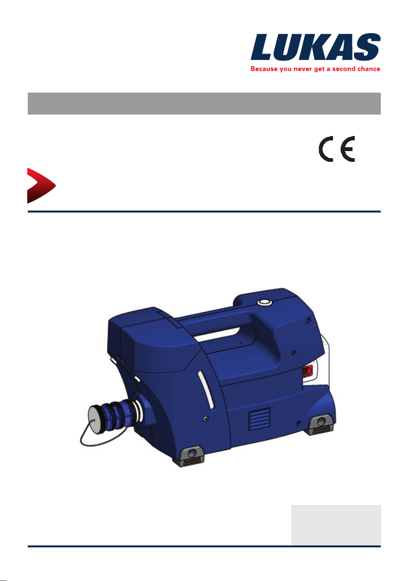
Hydraulic power unit P 600 OE
(Translation of the original instruction manual
175825085 EN
Edition 11.2014
replaces 01.2014

2

Contents Page
1. Danger classes 4
2. Product safety 5
3. Proper use 8
4. Functional description 9
4.1 Description 9
4.2 Structure of P600OE 11
5. Connecting the hoses / devices 12
6. Set-up and start-up 14
6.1 Installation 14
6.2 Commissioning 14
7. Operation 17
7.1 Operating the P600OE 17
7.2 Safety instructions 18
8. Dismantling the equipment / deactivation following operation 19
9. Tests 20
9.1 General information 20
9.2 Testing the devices 20
10. Maintenance and repair 22
10.1 General information 22
10.2 Preventive maintenance 22
10.3 Changing the hydraulic fl uid 23
10.4 Checking the fi lters 25
10.5 Changing the signs 25
11. Troubleshooting 26
12. Technical data 32
12.1 P600OE 33
12.1 P600OE 34
12.2 Noise emissions (based on the EN ISO 3744 standard) 35
12.3 Hydraulic fl uid recommendation 35
12.4 Operating and storage temperature ranges 35
12.5 Oscillation / vibration 35
13. EC Declarations of conformity 36
14. Accessories 37
14.1 Batteries 37
14.2 Battery charger 37
14.3 Power supply 38
15. Instructions regarding disposal 39
16. Notes 40
3
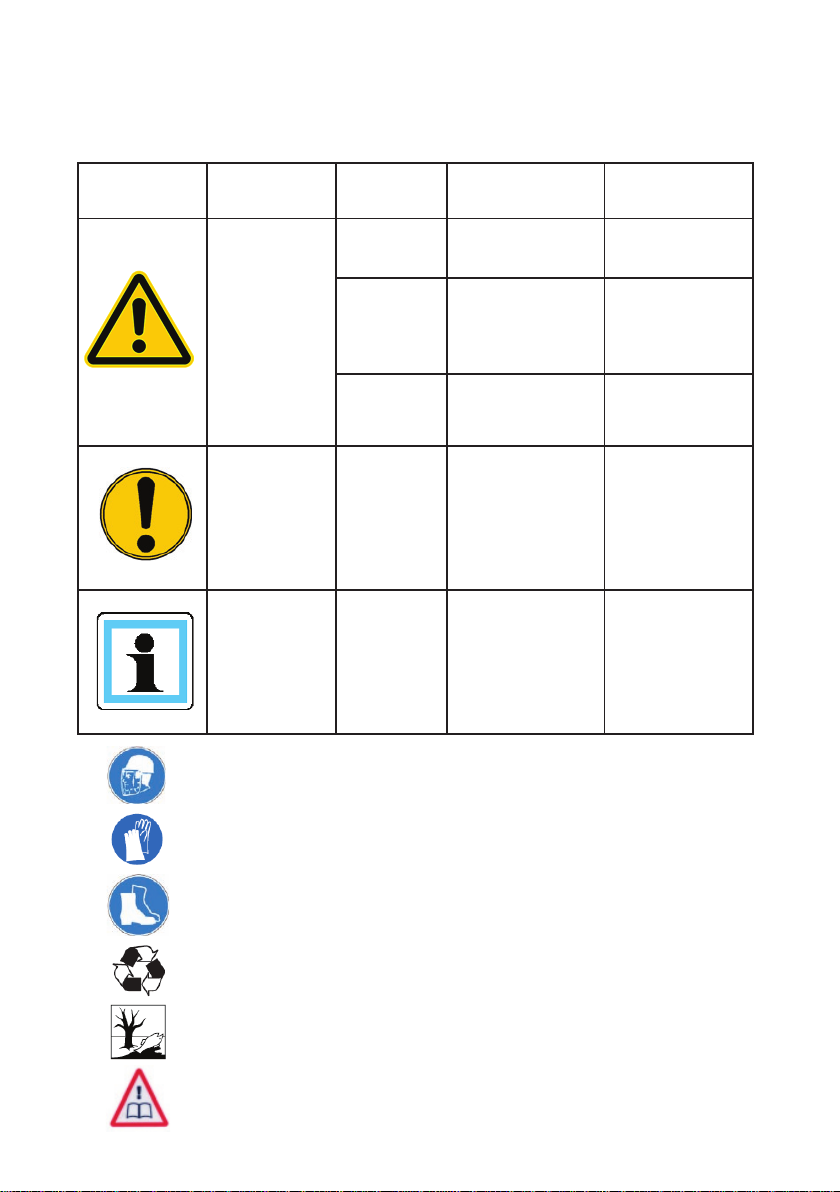
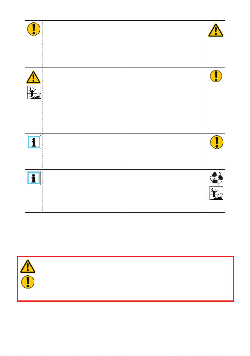
1. Danger classes
We distinguish between various categories of safety instructions. The table below provides
an overview of the symbols (pictograms) and signal words assigned to the specifi c danger
and also the possible consequences.
Pictogram
Damage /
injury to
Key word Defi nition Consequences
DANGER! Immediate danger
Death or severe
injury
WARNING!
Persons
CAUTION!
ATTENTION!
Property
- NOTE
Wear a helmet with a face guard
Wear protective gloves
Potentially
dangerous
situation
Less dangerous
situation
Danger of damage
to property/
environment
Handling tips and
other important/
useful information
and advice
Potential death or
serious injury
Minor or slight
injury
Damage to the
equipment,
damage to the
environment,
damage to
surroundings
No injury/damage
to persons/
environment/
device
Wear safety shoes
Proper recycling
Observe principles of environmental protection
Read and observe operating instructions
4
2. Product safety
LUKAS products are developed and manufactured to guarantee the best performance and
quality when used properly.
Operator safety is the most important aspect of the product design. Moreover, the operating
instructions are intended to aid the safe use of LUKAS products.
The generally applicable legal and other binding regulations pertaining to the prevention of
accidents and protection of the environment apply and are to be complied with in addition to
the operating instructions.
The device may only be operated by persons with appropriate training in the safety aspects
of such equipment – otherwise, there is a danger of injury occurring.
We would like to point out to all users that they should read the operating instructions
carefully before using the equipment and fully comply with the instructions therein.
We further recommend having a qualifi ed trainer showing you how to use the product.
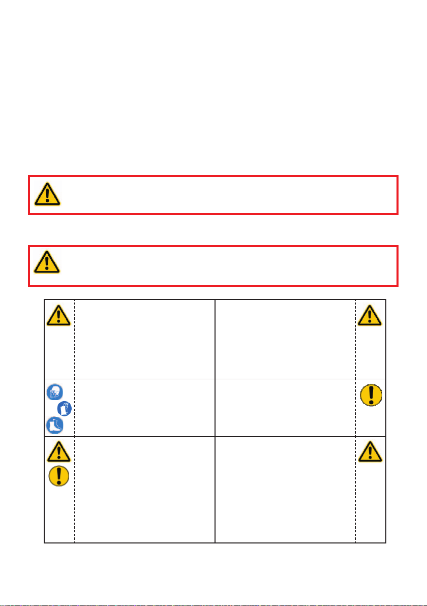
WARNING / CAUTION!
The operating instructions for the hoses, the accessories and the connected
hydraulic equipment must also be observed!
Even if you have already received instruction, you should read the following safety instructions
again.
WARNING / CAUTION!
Ensure that the accessories used and the connected equipment are suitable
for the maximum operating pressure!
Make sure that no body parts
or clothing get between the
openly visible moving parts of
the device.
Wear protective clothing,
protective helm with visor,
safety shoes and protective
gloves.
Working under loads is
prohibited if they are raised
exclusively with hydraulic
devices. If this work is
unavoidable, suitable
mechanical supports are also
required.
The department responsible
must be informed immediately
of any apparent changes
(including the operating
behaviour). If necessary, the
equipment is to be deactivated
immediately and secured!
Inspect the device before and
after use for visible defects or
damage.
Inspect all cables, hoses
and screwed connections
for leaks and externally
visible damage! If necessary,
repair immediately! Squirting
hydraulic fl uid can result in
injuries and fi res.
5
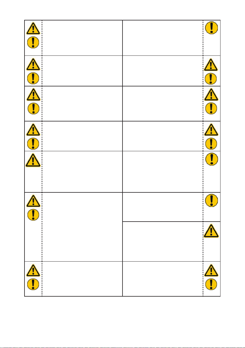
In the event of malfunctions,
shut down the device
immediately and make it safe.
Repair the fault immediately.
Observe all safety and danger
information on the device and
in the operating instructions.
Do not carry out any changes
(additions or conversions)
to the equipment without
obtaining the approval of
LUKAS beforehand.
All safety and danger
information on the device must
always be complete and in a
legible condition.
Make sure that all safety
covers are present on the
device and in proper working
condition.
Safety equipment must never
be disabled!
Make sure before switching
on/starting up the device and
during its operation, that this
will put no one in danger.
When working in the vicinity of
live components and cables,
appropriate measures must
be taken to avoid a transfer of
current or high-voltage arcing
to the device.
Any mode of operation which
compromises the safety and/
or stability of the device is
forbidden!
The maximum permissible
operating pressure must not
be changed.
Observe all intervals for
recurring tests and/or
inspections that are prescribed
or stated in the operating
instructions.
Use only original LUKAS
accessories and replacement
parts when carrying out
repairs.
When working with this
equipment or when
transporting it, ensure that you
do not get caught up in the
hose or cable loops and trip.
The build-up of static charge
and therefore possible
sparking must be avoided
when handling the device.
All damaged electrical
components e.g. scorched
cables, etc. are to be replaced
immediately!
6
When setting up the units, it
must be ensured that they are
not impaired by the infl uences
of extreme temperatures.
The device is fi lled with
hydraulic fl uid. These hydraulic
fl uids can be harmful to your
health if swallowed or if their
vapours are inhaled. Direct
contact with the skin must be
avoided for the same reason.
Please also note that hydraulic
fl uids can also adversely affect
biological systems.
Ensure adequate lighting
when you are working.
Always keep these operating
instructions easily accessible
at the place of operation.
Damage to electrical
components may only be
repaired by a qualifi ed
electrician in compliance with
all applicable national and
international safety guidelines
and regulations.
When working with or storing
the device, ensure that the
function and the safety is not
adversely affected by external
extremes of temperature and
that the equipment is not
damaged. Please note that the
device can also heat up over a
long period of use.
Before transporting the device,
always check to see that the
accessories are positioned
securely to prevent the
possibility of an accident.
Make sure you properly
dispose of all removed parts,
leftover hydraulic fl uid, leftover
oil and packing materials.
The generally applicable, legal and other binding national and international regulations
pertaining to the prevention of accidents and protection of the environment apply and are to
be implemented in addition to the operating instructions.
WARNING / CAUTION / ATTENTION!
If you still injure yourself on the hydraulic unit, clean the wound immediately and
consult a doctor to have it attended to!
If you get hydraulic fl uid in your eye, rinse it immediately several times with clear ,
clean water and consult a doctor!
Also, if you swallow hydraulic fl uid you should consult a doctor!
7
WARNING / CAUTION / ATTENTION!
The device is intended exclusively for the purpose stated in the operating instructions
(see chapter "Proper Use"). Any other use is not in accordance with its designated use.
The manufacturer/supplier cannot be held liable for any damage resulting from such use.
The risk of such misuse lies entirely with the user.
Proper use includes observance of the operating instructions and compliance with the
inspection and maintenance conditions.
Never work when you are overtired or intoxicated!
3. Proper use
The P600OE hydraulic unit is designed specially to supply hydraulic fl uid to a double-acting
LUKAS rescue unit.
The special feature of the P600OE is its compact lightweight construction. This means that
it is possible to work with hose-bound rescue equipment even in diffi cult to reach locations.
When working with this hydraulic unit, you must also observe all the regulations and directives
for safe and proper deployment of the connected rescue equipment.
The P600OE is NOT suitable for underwater deployment.
WARNING / CAUTION / ATTENTION!
The P600OE hydraulic unit is not explosion protected!
When using the equipment in explosion risk areas you must make sure that
operation of the unit does not trigger an explosion!
The responsibility for explosion prevention or for ruling out work with the P600OE
rests with the operator of the device or with the person responsible at the place
of use.
When working in areas at risk of explosion, all applicable legal,
national and international regulations, standards and safety rules
for preventing explosions must be observed without exception!
The equipment should not come into contact with acids or alkalis. If this is
unavoidable, clean the equipment immediately afterwards with a suitable
cleaning agent.
8

Y ou can order replacement parts and accessories for LUKAS equipment from your authorised
LUKAS dealer!
4. Functional description
4.1 Description
The P600OE is a compact lightweight electrically driven hydraulic pump. It is designed for
supplying hydraulic power to a double-acting LUKAS rescue unit.
Their use for supplying pressure / fl uid to rescue equipment of other manufacturers is possible,
yet requires the technical inspection and approval by LUKAS in each individual case.
CAUTION!
When selecting the units to connect to the unit, bear in mind that the maximum
possible useable volume of hydraulic fl uid is limited.
The max. required operating volume (hydraulic fl uid) of the connected unit must
not exceed the maximum possible useable volume of the hydraulic pump!
The volume of the tank on the P600OE is designed so that all LUKAS cutters, spreaders,
combi tools and the R410 and R412 rescue cylinders that are fi tted with Streamline can
be operated. The energy source for the P600OE can be either a mains power unit or an
accumulator battery. The mains power units and accumulator batteries that fi r into this
hydraulic unit can also be used for the LUKAS eDRAULIC units. When working with the
P600OE you can choose which energy source to use. Both the accumulator battery and the
mains power unit can be inserted in the opening provided in the body of the tool. Both will
lock in place automatically.
NOTE:
When connecting to the mains, if a very long connecting cable is used, the power
supply to the motor may be reduced as a result of the resistance in the cable.
This will reduce the power of the motor.
The hydraulic unit operates in two modes, the WORKING mode and the ECO mode.
It switches to mode required automatically.
In the WORKING mode, the P600OE provides the rescue unit with maximum volume
fl ow of the hydraulic fl uid at maximum pressure. In the ECO mode, we employ a special
speed drop facility. This mode facilitates a very long pump running time with the battery
charge. The speed drop facility reduces the volume fl ow of hydraulic fl uid to a minimum.
The P600OE automatically switches to the ECO mode after 2-3 seconds if the control valve
on the connected rescue unit is not being operated, in other words, when it is in neutral setting.
As soon as the control valve on the rescue unit is actuated, the pump switches automatically
to the WORKING mode. You now have the maximum power of the P600OE available.
The response time of the switchover from ECo to WORKING mode is less than 0.5 s and is
therefore hardly noticeable. The noise of the motor tells you which mode the hydraulic unit
is using.
At reduced temperatures (from approx. 5 °C) it switches to the ECO mode. The P600OE then
runs permanently in working mode. As soon as the oil has heated up, the normal function is
available again.
9

In addition, the P600OE is fi tted with LED lighting as standard in order to make working
under reduced visibility conditions easier.
The light-emitting diodes attached on the connection side light up the coupling area. The
main switch has also been provided with a light, so that you can see at a glance whether
the device is switched on.
The hydraulic tank is also lit. This allows you to see the fi ll level at any time if the lighting
conditions are poor.
The P600OE is fi tted with a single fl ow pump with two pressure stages, a low pressure stage
and a high pressure stage.
Low pressure stage (ND) = up to 14 MPa*
High pressure stage (HD) = up to 70 MPa*
The changeover from low pressure to high pressure is carried out automatically in the pump.
The maximum pressure is limited by a pressure limiting valve.
Connection with the rescue equipment is via extension hose pairs or a hose reel. They are
supplied in various lengths and kink-protection colours. The individual hoses in a pair of
hoses can be distinguished by their different colours.
(For specifi c details, please consult the LUKAS range of accessories or contact your
LUKAS dealer.
Lukas recommends that you do not use more than 10 m of total hose
length between the hydraulic pump and the rescue unit.
NOTE:
Always register your hydraulic unit on the LUKAS Hydraulik GmbH internet site.
Only then are you entitled to the extended guarantee.
Before you use couplings from a different company , you must contact LUKAS or
an authorised dealer.
You can order replacement parts and accessories for the P600OE from your authorised
LUKAS dealer!
*) 1 MPa = 10 bar)
10
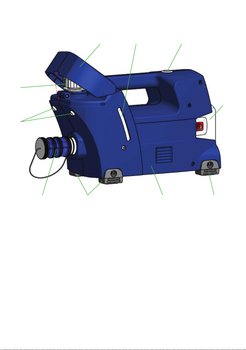
4.2 Structure of P600OE
2 9
3
6
4
881
5
7
1 Casing
2 Filler cover
3 Filler cap
4 Mono-coupling sleeve
with dust cap
5 ON / OFF switch
6 LED lighting
7 Battery or mains power
unit
8 Rubber buffer
9 Fill level display
(illuminated)
11
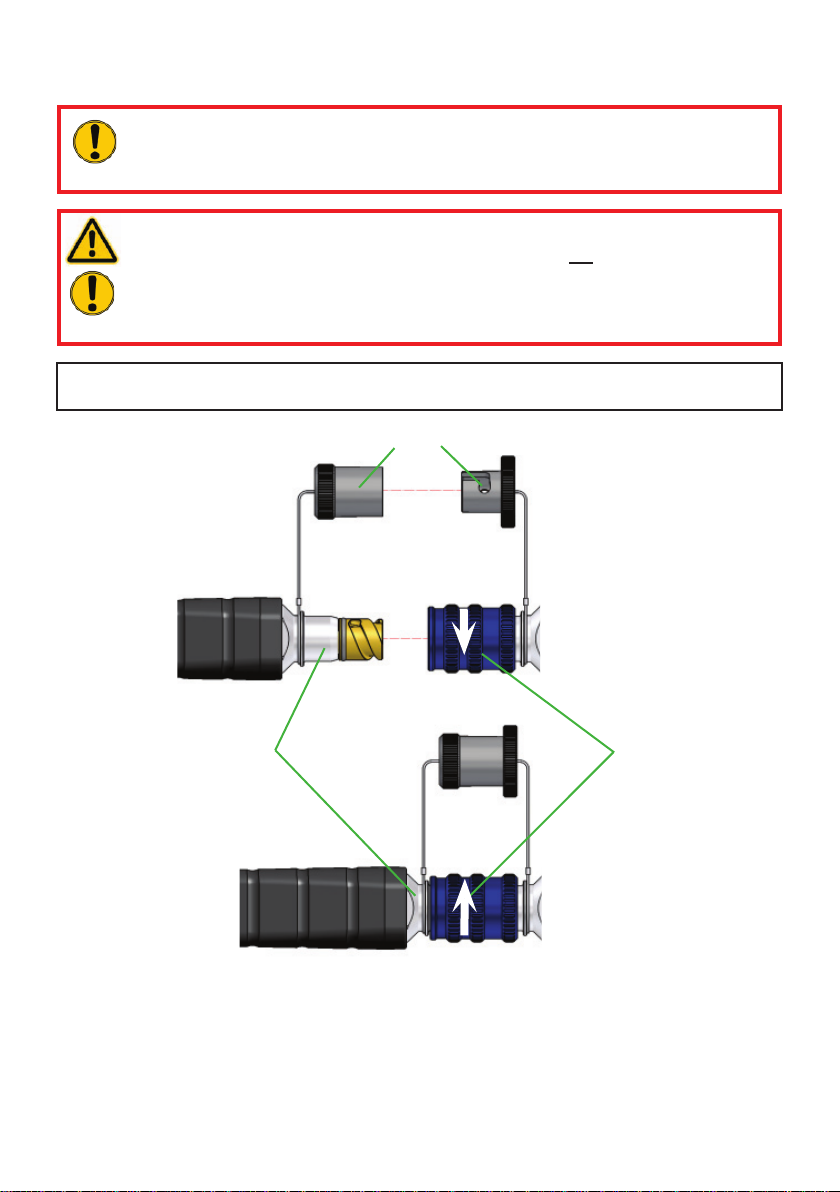
5. Connecting the hoses / devices
CAUTION!
When connecting the hose assemblies / units, always ensure that the connection
components are not soiled. If necessary, clean immediately!
WARNING / CAUTION / ATTENTION!
Before connecting equipment, make sure that all the components
used are suitable for the maximum operating pressure of the
hydraulic unit! In cases of doubt, you must consult LUKAS
directly before connecting the equipment!
The hose lines / units are connected via quick-disconnect coupling halves (female and male)
to the hydraulic pump in such a way that they cannot be reversed.
Dust protection caps
0
Male coupling
1
0
Remove the dust caps before coupling together. Then push the male and female parts
together and turn the locking sleeve on the female coupling in the direction "1" until the
locking sleeve clicks in place. The connection has now been made and locked. Uncoupling
is accomplished by turning the locking sleeve in direction "0".
12
Female coupling
NOTE:
Couple together only when in ECO mode, or when the P600OE is switched off!
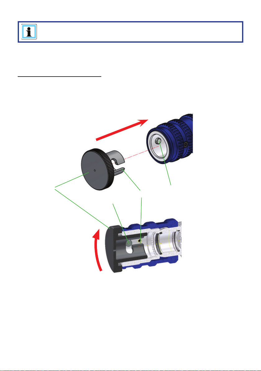
For dust protection, the supplied dust protection caps must be refi tted.
Fitting the dust protection caps:
The dust protection caps "A" have two external grooves "B". The dust protection caps must
be inserted in the female coupling in such a way that the grooves can be guided over the pins
"C". Screw in the dust protection caps to the limit stop to fi x in the female couplings.
A
B
C
13
C

6. Set-up and start-up
6.1 Installation
WARNING / CAUTION / ATTENTION!
The LUKAS Mini electric pump is not explosion protected!
When using the equipment in explosion risk areas you must make sure that
operation of the unit does not trigger an explosion!
The unit is to be set up in a suitable location (safe location / fl at surface / suffi cient distance
from vehicles, loads, sources of ignition, etc.).
LUKAS units work perfectly at an angle of up to 20°. However, in order to guarantee maximum
safety and fl uid withdrawal, they should be operated in as horizontal a position as possible.
The P600OE is designed in such a way that, when deactivated and with correctly fi tted fi ller
cap, no hydraulic fl uid can leak out, even if the pump were to tip over.
6.2 Commissioning
NOTE:
When delivered the hydraulic fl uid in the P600OE has a special High-Tech
running in additive mixed in. This can be seen with the different colour of the
hydraulic fl uid when the pump is delivered.
The additive optimises the running-in behaviour and the hydraulic function of the
pump. When topping up or fi lling with hydraulic fl uid, you should always observe
Item 12.3 in this manual.
Before starting up for the fi rst time, the battery (if fi tted) must be fully charged in an external
charger.
Commissioning procedure:
1. First check the condition of the pump.
- The casing should not be damaged.
- Hydraulic fl uid should not be coming out in an uncontrolled manner.
- The coupling should not be damaged
- The battery connection slot should not exhibit any function-inhibiting damage.
2. Then check the level of hydraulic fl uid in the in the pump.
The fl uid levels can be read off on the fi ll level indicator on the side of the unit. There are
3 marks on the fi ll level indicator. For precise reading off of the fl uid levels and for fi lling,
the hydraulic unit should be as level as possible.
14

Maximum fi ll level
Minimum fi ll level
The hydraulic fl uid level should never fall below this level,
even when the unit is running, since otherwise the pump will
be damaged!
3. If necessary, fi ll with hydraulic fl uid up to the maximum level.
Filling with hydraulic fl uid is carried out as possible:
a) Open the fi ller cover completely. Slight resistance must be overcome to open it.
This is designed to prevent inadvertent opening of the cover.
15

The fi ller cover can also be removed completely to make fi lling easier. To do this
open the fi ller cover by approx. 35° and pull the cover off towards the coupling.
Do not use force since this could damage the cover.
1. 2.
NOTE:
Do not fi ll up to the maximum mark because otherwise hydraulic fl uid
could come out of the fi ller cap when running.
b) Open the fi ller cap on the fl uid tank.
c) Fill with hydraulic fl uid up to the maximum mark.
You should use a funnel for fi lling to prevent spilling the hydraulic fl uid.
d) Close the tank again with the fi ller cap and remove any spilled hydraulic fl uid with
a suitable cloth.
e) Replace the fi ller cover (if removed) and close completely. It clicks into place when
closed.
16

4. Now insert the battery or the mains adapter into the unit (if not already fi tted). The mains
adapter must then be connected to the power supply.
5. The hydraulic unit must now be bled. This takes place fully automatically on the P600OE.
T o carry out bleeding you just have to switch the hydraulic pump on at the main switch and
let it run for two to three minutes without having a unit connected to it.
The fi ller cap is also fi tted with a vent which automatically bleeds the tank when the pump
is running.
6. After bleeding, check the level of fl uid in the tank again. Top up if necessary.
7. Finally, you can now connect the extension hoses or hose reels and/or connect the rescue
equipment directly.
7. Operation
7.1 Operating the P600OE
The P600OE has been designed to provide the user with the simplest method of operation.
For this reason, the pump only needs to be switched on and off and the rescue unit be connected to it. All the other functions are carried out fully automatically.
However, always connect the rescue unit before switching the hydraulic unit on. After switching on, the initiation sequence on the unit is run. This takes approx. 3 seconds. During this
period the LED in the main switch fl ashes and the motor runs for approx. 1.5 secs. in ECO
mode and approx. 1.5 secs. in working mode. As soon as the LED lights up permanently in
the main switch you can start working with the connected rescue equipment. If the connected
unit is not actuated, the unit switches back to the ECO mode after a few seconds.
CAUTION!
If a rescue unit is actuated during the initiation sequence, the pump could
inadvertently switch to the ECO mode during operation. T o restore full functionality
switch the pump off, switch it on again and allow the initiation sequence to run
as described above.
17

7.2 Safety instructions
World-wide, safety guidelines pertaining to the specifi c country must be observed and
complied with. In the Federal Republic of Germany, regular safety inspections according
to the legal accident insurance regulations (GUV - Gesetzliche Unfallversicherung) are
mandatory .
Wear the following when working with the unit:
- protective clothing,
- safety helmet with visor or protective goggles,
- protective gloves
- and, if necessary, ear protection
Always make sure that, before actuating the unit, no participating and/or non-participating
persons will be exposed to danger by the work with the unit or by working with the connected
rescue equipment!
WARNING / CAUTION!
When working, hydraulic fl uid can be emitted by damage to the unit or the hoses.
Since the units operate at a very high hydraulic pressure, hydraulic fl uid being
emitted can cause severe to the severest injury to persons. Those not involved
in the rescue operation should therefore keep at a distance appropriate to the
situation. Any trapped or enclosed persons must be protected.
In order to prevent such dangers, all measures must be taken to prevent damage
to the units and hoses!
18

8. Dismantling the equipment / deactivation
following operation
Procedure:
1. When the work is completed, the connected units must be returned to the starting
position.
This should mean that the hydraulic tank on the P600OE has the starting volume of
hydraulic fl uid.
2. Then switch off the device at the main switch.
3. Separate the connected unit from the hydraulic unit.
4. After each use, the pump must be cleaned externally and wiped down with a damp cloth.
CAUTION!
The electric contacts in the connection slot, on the battery and on the
mains power unit must not be cleaned with damp cloths! There are suitable
agents to provide corrosion protection for the electrical contacts.
5. Unplug the power supply (if used) by pulling the mains plug.
6. Fully press down the two unlocking buttons and carefully pull the battery or power
supply out of the device.
Do not use force!
Connection slot
NOTE:
You should not store the hydraulic unit for several weeks with the battery
in place.
Bear in mind that, if the unit is stored for an extended period, the hydraulic
fl uid in the tank will age and needs to be replaced at regular intervals .
Do not store the pump, the battery and the mains power unit in a damp or
dusty environment!
19

9. Tests
9.1 General points
The P600OE is subject to very high levels of mechanical loading as a result of the high
operating pressure. A visual inspection must therefore be carried out after every use and at
least one visual inspection must be carried out every six months. These inspections enable
the early detection of wear and tear, which means that punctual replacement of these
wearing parts prevents damage.
CAUTION!
Clean off any dirt before checking the device!
When cleaning the equipment, take care not to use any cleaning agent with a pH
value outside the range 5 - 8!
WARNING / CAUTION / ATTENTION!
In order to carry out maintenance and repair work, tools appropriate for the job
and personal protection equipment must be used.
The maintenance and repair staff must have adequate technical and specialised
knowledge. LUKAS offers appropriate training courses for this.
9.2 Testing the devices
An annual inspection of the tool is due once per year. This inspection must be performed by
a person with the necessary expertise. This means that the person must possess adequate
specialist knowledge and experience in the fi elds of electrical engineering and hydraulics, so
that they can objectively assess the condition of the tool.
At least every 3 years or when there might be doubts regarding the safety or reliability of
the unit, an additional function check is to be carried out (in this connection, comply with the
applicable national and international regulations with regard to the maintenance intervals of
rescue equipment). In the Federal Republic of Germany , regular safety inspections according
to the legal accident insurance regulations (GUV - Gesetzliche Unfallversicherung) are
mandatory .
We recommend carrying out a function check at the following intervals:
Operating time per day Functional check
up to 1 hour 1 x annually
up to 8 hours 1 x per quarter
up to 24 hours 1 x per month
In addition to these test intervals you need to carry out a function test if:
- the unit makes suspicious noises,
- there is a justifi ed suspicion of internal damage to the unit.
20

If the noises and suspicions referred to above arise several times in a month, or if maximum
pressure cannot be achieved during the function test, you need to contact LUKAS customer
service immediately. The contact details are given in the Chapter "Fault analysis".
Inspections to be carried out:
Visual inspection
• No visible damage to the housing,
• General tightness (leaks),
• ON/OFF switch in proper working order, undamaged
• Couplings must be easy to couple,
• Dust protection caps must be present
• Labels completely existent and legibly,
• Illumination of main switch, work area and tank illumination fully functional.
Battery and power supply
• Casing undamaged,
• Electrical contact surfaces clean and undamaged
• Cable undamaged
• Battery(-ies) fully charged (when used)
• Charging state display of lithium/ion battery(-ies) fully functional
Functional check
• no suspicious noises,
• tests at maximum load. When the maximum pressure is achieved, the pump switches
to the ECO mode after a short time. As soon as the pressure drops slightly, the pump
automatically switches back to the working mode.
(Recommendation: use the LUKAS test kit, including testing instructions, for the function test).
21

10. Maintenance and repair
10.1 General points
NOTE:
Always register your tool on the LUKAS Hydraulik GmbH internet site. Only then
are you entitled to the extended guarantee.
Because of the complex construction and the high hydraulic pressure, repair work must
only be carried out by the unit manufacturer or by personnel specially trained by the unit
manufacturer and by authorised LUKAS dealers.
For these reasons, only simple maintenance work is listed in this manual.
Components of the unit must only ever be replaced by genuine LUKAS spare parts.
The components that can be replaced are shown in the spare parts list. Also, any necessary
special tools, installation instructions, safety aspects, tests that always need to be observed
can be found in the spare parts list.
During assembly, make especially sure that all components are clean, since dirt can
damage the rescue tool!
WARNING / CAUTION / ATTENTION!
Protective clothes must be worn when repairs are being carried out, since the
devices may also be pressurised when not in operation.
10.2 Preventive maintenance
10.2.1 Care instructions
The unit should be cleaned externally with a damp cloth from time to time (not the electrical
contacts in the connection slot, on the battery and on the mains unit)
There are special agents for treating the electrical contacts, that are suitable for cleaning and
providing corrosion protection for the electrical contacts. Use must only use these agents on
the contacts.
(In case of doubt, contact your authorised LUKAS dealer or LUKAS directly!)
10.2.2 Functional and stress test
If there is any doubt regarding the safety or reliability of the equipment, a function and stress
test must also be performed.
LUKAS offers appropriate testing equipment for this.
22

10.3 Changing the hydraulic fl uid
After approx. 200 deployments, but after three years at the latest, replace the hydraulic fl uid.
The fl uid should be replaced when it is warmed up. When replacing the hydraulic fl uid, the
pump must be deactivated and the battery or the mains unit must be removed from the
connection slot.
The old hydraulic fl uid must be disposed of properly.
Procedure:
1. Open the fi ller cover. Removal of the fi ller cover will make the subsequent tasks easier.
1. 2.
2. Remove the fi ller cap on the fl uid tank.
23

3. Pour the hydraulic fl uid into a suitable collection vessel.
4. Place the P600OE on level, fl at ground and fi ll up to the maximum mark.
5. Then close the tank again with the fi ller cap and insert the battery into the connection
slot or connect the pump to the power supply.
6. Switch the pump on and let it run for approx. 2-3 minutes. This bleeds the pump.
7. Check the level in the tank again and top up if necessary.
8. Then fi t the fi ller cover back in place and close off the tank access on the unit.
24

10.4 Checking the fi lters
The air inlet fi lter should be checked at least once a year. The fi lter can be checked from the
outside if the mains unit (or battery) is removed (see illustrations below).
If the fi lter is severely contaminated, it will need to be replaced. At the same time, the fi lters
in the air exhaust must be replaced. To do this, the housing must be opened up by trained
personnel and the fi lter replaced (see also spare parts list).
Procedure:
1. Tilt the P600OE as shown in the illustrations.
2. Check the status of the fi lter.
10.5 Changing the labels
All damaged and/or illegible labels (safety instructions, type plate, etc.) must be renewed.
Procedure:
1. Remove damaged and/or illegible labels.
2. Clean surfaces with industrial alcohol.
3. Affi x new labels.
Take care to affi x the labels in the correct positions. If you are no longer sure about this, then
please contact your authorised LUKAS dealer or LUKAS itself.
25

11. Troubleshooting
Fault Check Cause Solution
The PO600OE
switches
inadvertently to the
Eco mode when
working with a
rescue unit
The initiation sequence
period of 3 seconds
is not allowed to be
carried out
Switch the pump off
and on again. Use the
rescue unit only after
the initiation sequence
has been fully carried
out. Flashing light
in the on/off switch
goes to permanent
light (see also
Paragraph 7.1)
Electric motor does
not start following
activation of the
main switch
Battery or mains
unit positioned
correctly in the
connection slot
and locked in
position
Check connection
of mains unit
Correct battery
fi tted?
Battery or mains unit
not inserted properly
Mains unit cable not
connected
Incorrect battery Use stipulated battery
Battery fl at Charge battery
Battery or mains unit
defective
Fault in power supply to
the mains unit
Remove the battery
or mains unit from the
pump and re-insert.
Connect mains unit
cable to the power
supply
Use a different battery
or mains unit.
Troubleshooting the
power supply
Use a different power
supply
P600OE defective Shut down immediately
and have repaired by
authorised service
facility, authorised
dealer or directly by
LUKAS
26

Fault Check Cause Solution
P600OE stops
during operation
Battery or mains
unit positioned
correctly in the
connection slot
and locked in
position
Battery or mains unit
not inserted properly
Remove the battery
or mains unit from the
pump and re-insert.
Electric motor not
providing full power
Check connection
of mains unit
Check battery
charge status
Mains unit temperature
too high as a result
of continuous use
and high ambient
temperature
Mains unit not correctly
connected
Cable losses in
extension cable or
cable drums too great
(electrical resistance)
Mains unit fault Use a battery or
Battery almost fl at Charge battery
Battery defective Replace battery
Fault in power supply to
the mains unit
Allow mains unit to cool
down (see operating
instructions of mains
unit)
Re-insert the mains unit
Use a different suitable
extension cable or cable
reel or connect directly
to power supply
different mains unit.
Troubleshooting the
power supply
Use a different power
supply
P600OE defective Shut down immediately
and have repaired by
authorised service
facility, authorised
dealer or directly by
LUKAS
27

Fault Check Cause Solution
Pump does not
switch to WORKING
mode after actuating
the connected
rescue unit
Initiation sequence
not allowed to run
completely
Control valve of
connected rescue unit
actuated too slowly or
too tentatively.
Switch unit off, then
switch it on again and
wait for initiation
Actuate the control
valve again.
Pump does not
switch back to ECO
mode
The motor / engine
is running, but the
connected rescue
equipment is not
moving / moving
very slowly upon
activation of the
valve.
Rescue unit not
connected correctly
(locking sleeve on
the coupling not fully
rotated to "1")
Too low ambient
temperature
Check hose Hose assembly not
connected properly or is
damaged
Connect a
different unit and
check whether
it works when
actuated
The previously
connected unit is
defective.
Mono-coupling (female)
defective
P600OE defective Shut down immediately
Turn the locking sleeve
on the coupling fully to
the end position "1".
No repair or fault
rectifi cation required
Check connection of
hose and reconnect if
necessary.
Rectifi cation see
operating instructions of
the connected unit
Replace mono-coupling
(female)
and have repaired by
authorised service
facility, authorised
dealer or directly by
LUKAS
28

Fault Check Cause Solution
The connected
rescue equipment
does not move on
activation of the
valve, or moves
only very slowly or
unevenly.
Connect a
different unit and
check whether
it works when
actuated
The previously
connected unit is
defective.
Air in the hydraulic
supply
Rectifi cation see
operating instructions of
the connected unit
Vent the hydraulic
system.
Leaks from pump
body itself
Connected rescue
device does not
reach its fi nal
position
Check hydraulic
fl uid volume in
hydraulic reservoir
Mono-coupling on
connection hose is
defective
Mono-coupling (female)
defective
P600OE defective Shut down immediately
P600OE defective Shut down immediately
Insuffi cient fl uid in the
hydraulic reservoir
Replace connection
hose
Replace mono-coupling
(female)
and have repaired by
authorised dealer, motor
/ engine manufacturer
or directly by LUKAS
and have repaired by
authorised service
facility, authorised
dealer or directly by
LUKAS
Top up hydraulic fl uid
to the maximum fi lling
level
Important! Before
topping up the rescue
equipment, return to
the base position!
Usable hydraulic fl uid
volume of the unit is
insuffi cient
29
Use a different rescue
device with a demand
quantity below the
maximum usable
quantity of the unit

Fault Check Cause Solution
Connected rescue
device does not
reach its specifi c
performance data
Maximum permitted
operating pressure of
the pump is not reached
Have repaired by
authorised service
facility, authorised
dealer or directly by
LUKAS
During function test:
A pressure gauge
installed between the
rescue equipment
and the hydraulic
power pack does
not indicate the
maximum operating
pressure of the
equipment.
Maximum pressure
not achieved
Check the details
of the rescue
device
Connected unit
defective
The operating pressure
of the connected
rescue device is locked
internally
Connected rescue
device is defective
Hydraulic unit defective Have repaired by
Mono-coupling on
connection hose is
defective
Hydraulic unit defective Have repaired by
Rectifi cation see
operating instructions of
the connected unit
No repair or fault
rectifi cation required
Rectifi cation see
operating instructions of
the connected unit
authorised service
facility, authorised
dealer or directly by
LUKAS
Replace connection
hose
authorised service
facility, authorised
dealer or directly by
LUKAS
30

Fault Check Cause Solution
Fluid coming out
from hydraulic fl uid
tank
Connected unit
not in base
position yet and
fl uid coming out of
fi ller cap?
Return of the hydraulic
fl uid from the rescue
device exceeds the
reservoir’s maximum
quantity when fi lled.
Reduce fl uid level in
the hydraulic tank to
"Minimum" mark, move
the unit to the base
position and then fi ll
back up with hydraulic
fl uid to the "Maximum"
level
Fluid leaks from a
different location?
Hydraulic fl uid milky
and cloudy
Hose lines cannot be
coupled
It is frequently not
possible to couple
hose assemblies
Leak in the couplings Is the coupling
damaged?
Leak from tank, lines or
seals
Water or condensation
water in the system
Coupling defective. Coupling must be
Coupling defective. Coupling must be
Coupling defective. Coupling must be
Replace defective
components or repair
by authorised dealer or
Lukas directly
Replace hydraulic fl uid
immediately
replaced immediately.
replaced immediately.
replaced immediately.
The useful operating
time between the
individual charging
cycles is less
than 15 minutes,
despite charging the
batteries according
to the instructions.
Battery defective Replace battery
31

If you cannot rectify the malfunctions, inform an authorised LUKAS dealer or the LUKAS
customer service department immediately!
The address of the LUKAS Customer Service Department is:
LUKAS
Weinstraße 39, Erlangen, 91058 Germany
Phone: (+49) 09131 / 698 - 348
Fax.: (+49) 09131 / 698 - 353
Hydraulik GmbH
12. Technical data
Since all values are subject to tolerances, minor differences may occur between the data on
your equipment and the data in the following tables.
The values may also differ because of reading inaccuracies and/or tolerances in the
measuring equipment used.
NOTE:
The following tables contain only the technical data necessary for operation and
storage.
Further information about your device is available directly from LUKAS.
32

12.1 P600OE
Type P 600 OE
Item number
Dimensions (excluding battery)
L x W x H
Motor power rating
Max. operating pressure
1)
(HD)
Volume fl ow
1)
(HD)
Max. operating pressure
2)
(ND)
Volume fl ow
2)
(ND)
Max. fi ll volume
Hydraulic fl uid
81-53-10
(175825000)
[mm] 460 x 182 x 257
[in.] 18.11 x 7.17 x 10.12
[kW] 1.0
[HP] 1.34
3)
[MPa]
70
[psi.] 10000
[l/min] 0.45
[gal.-US/min] 0.12
3)
[MPa]
14
[psi.] 2
[l/min] 2.4
[gal.-US/min] 0.64
[l] 1.5
[gal.-US] 0.40
Max. usable volume
Hydraulic fl uid
Weight (without battery with
hydraulic fl uid)
Weight (with battery and hydraulic fl uid)
Weight (with mains unit and
hydraulic fl uid)
Nominal electrical voltage
(with power supply)
Nominal electrical voltage
(with lithium/ion battery)
1)
HD = High-pressure
2)
ND = Low pressure
[l] 1.2
[gal.-US] 0.32
[kg] 8.3
[lbs.] 18.3
[kg] 9.2
[lbs.] 20.3
[kg] 10.0
[lbs.] 22.05
[V] 25
[V] 25.2
3)
1MPa = 10 bar
33

12.1 P600OE
Power consumption at full load [A] 40
Max. power consumption 230VAC
(with eDraulic Power Supply 230 VAC)
Starting current 230VAC (with eDraulic
Power Supply 230 VAC)
Max. power consumption 110VAC
(with eDraulic Power Supply 110 VAC)
Starting current 110VAC (with eDraulic
Power Supply 110 VAC)
[A] 7
[A] 16
[A] 10
[A] 22
Protection category IP54
Max. permissible hose length
[m] 10
[ft.] 32.81
1)
HD = High-pressure 2)ND = Low pressure
3)
1MPa = 10 bar
34

12.2 Noise emissions (based on the EN ISO 3744 standard)
Used power source Lithium-ion battery Power supply
Idling (measured at
a distance of 1 m)
Full load
(measured at a
distance of 1 m)
Idling (measured at
a distance of 4 m)
Full load
(measured at a
distance of 4 m)
[dB(A)] 54 54
[dB(A)] 71 71
[dB(A)] 53 53
[dB(A)] 67 67
12.3 Hydraulic fl uid recommendation
Mineral oil DIN ISO 6743-4 for LUKAS hydraulic equipment and others
Oil temperature range Oil code Viscosity rating Remarks
A -20 .... +55°C HM 10 VG 10
Oil temperature range Oil code Viscosity rating Remarks
A
recommended viscosity range: 10...200 mm²/s (10…200 cSt.)
Supplied with HM 10 DIN ISO 6743-4.
-4.0 .... +131°F HM 10 VG 10
CAUTION!
Before you use hydraulic fl uids from a different manufacturer, you must contact
LUKAS or an authorised dealer.
12.4 Operating and storage temperature ranges
Operating temperature [°C] / [°F] -20 … +55 -4 … +131
Ambient temperature
(device in operation)
Storage temperature
(device not in operation)
[°C] /
[°F] -25 … +45 -13 … +113
[°C] /
[°F] -30 … +60 -22 … +140
12.5 Oscillation / vibration
The total oscillation value / vibration value to which the upper limbs are exposed, is below
2.5 m/s².
35

13. EC Declarations of conformity
36

14. Accessories
14.1 Batteries
Only LUKAS lithium-ion rechargeable batteries may be used to operate the P600OE.
These guarantee optimum performance and maximise the operating time of the units.
Charging
state
indicator
Query
button
NOTE:
Pay strict attention to the separate operating instructions for the battery.
14.2 Battery charger
Only the "eDRAULIC Power Pack Charger" may be used for the lithium/ion batteries.
NOTE:
Pay strict attention to the separate operating instructions for the battery charger.
37

14.3 Power supply
The P600OE has a unique power supply with integrated electronics, allowing the devices to
be operated for an almost unlimited time by connecting them to an external power source.
The power supply converts the voltage of the external power source in such a way that it may
be used instead of a battery.
Cable
Filter
Adapter
Cable
Mains plug
Structure:
There is an adapter on one side of the power supply which can be simply inserted into
the connection slot of the devices and locked. The other side has a mains plug. Both are
connected by a cable. The mains plug is a Schuko plug with Protection Classifi cation IP68.
The integrated fi lter is appropriate for the conversion of AC voltage to DC voltage.
NOTE:
Pay strict attention to the separate operating instructions for the power supply.
38

15. Instructions regarding disposal
Please properly dispose of all packing
materials and removed parts.
Electrical equipment, accessories and packaging should always be disposed of in an
environmentally compatible way.
Only for EU countries:
Do not dispose of electrical equipment with your household waste!
According to the European Directive 2002/96/EC governing electrical and electronic waste
and their application in national legislation, old electrical equipment must be separately
collected and recycled in an environmentally compatible manner.
Please also take into account the notes in the separate operating instructions for the batteries.
39

16. Notes
40

414243


LUKAS
A unit of the IDEX Corporation
Weinstraße 39, Erlangen, 91058 Germany
Phone: (+49) 0 91 31 / 698 - 0
Fax.: (+49) 0 91 31 / 698 - 394
e-mail: lukas.info@idexcorp.com
www.lukas.com
Hydraulik GmbH
Made in GERMANY
© CopyTRUE 2012 LUKAS Hydraulik GmbHP600OE_manual_175825085_en.indd
 Loading...