

Page 1
Operating Instructions
Rescue Tools
Rescue Rams
LZR
12/550 PS
1
1.1
3
5
9
6
2
8
4
10
11
12
84150/6106-85 GB
Issue 04.2006
replaces 09.2005
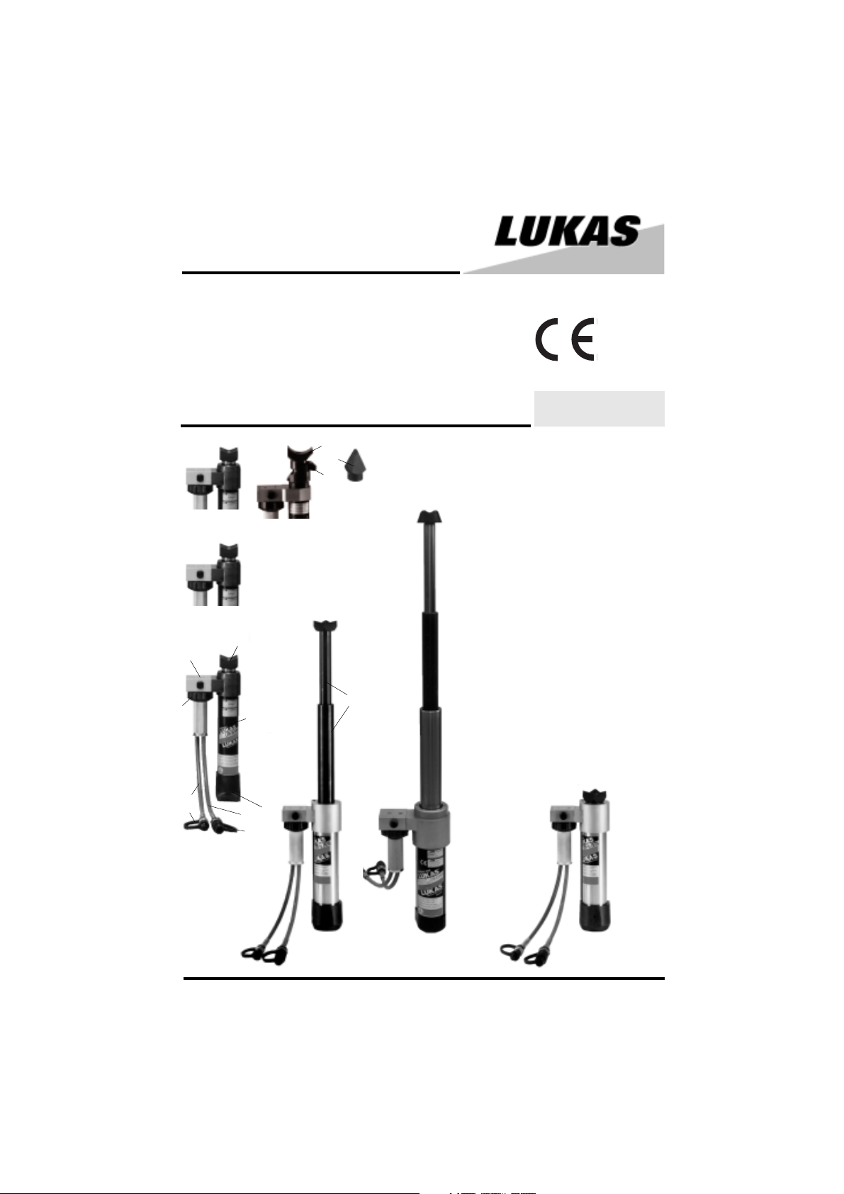
1 Control valve with star ring 1.1
2 Hose, black: Pressure
3 Hose, blue: Return
4 Quick-connect socket StMu 61 - 0
5 Quick-connect plug StNi 61 - D
6 Hydraulic cylinder
7 Piston rod
8 Claw, cylinder side
9 Claw, piston side
10 Peeling tip
11 Penetration tip
12 Counterpart for peeling
7
LZR 12/...
LTR 6/570 LTR 3,5/820EN
1
LZR 19/325
Page 2

1 Basic operation and designated use of the machine
1.1 The machine has been built in accordance with state-of-the-art standards and the
recognized safety rules. Nevertheless, its use may constitute a risk to life and limb of the user or
of third parties, or cause damage to the machine and to other material property.
1.2 The machine must only be used in technically perfect condition in accordance with its
designated use and the instructions set out in the operation manual, and only by safety-conscious
persons who are fully aware of the risks involved in operating the machine. Any functional
disorders, especially those affecting the safety of the machine/plant, should therefore be rectified
immediately!
1.3 The machine is exclusively designed for the use described in the operating manual. Using
the machine for purposes other than those mentioned in the manual, such as driving and controlling
other pneumatic systems, is considered contrary to its designated use. The manufacturer/supplier
cannot be held liable for any damage resulting from such use. The risk of such misuse lies entirely
with the user.
Operating the machine within the limits of its designated use also involves observing the
instructions set out in the operating manual and complying with the inspection and maintenance
directives.
2 Organizational measures
2.1 The operating manual must always be at hand at the place of use of the machine!
2.2 In addition to the operating instructions, observe and instruct the user in all other generally
applicable legal and other mandatory regulations relevant to accident prevention and environmental
protection.
This also applies for wearing protective clothing, helmet with visor or goggles and protective
gloves.
2.3 In order to avoid innjuries, the machine must only be operated by a specially trained operator
who has undergone a safety training.
2.4 Observe all safety instructions and warnings attached to the machine. Make sure that safety
instructions and warnings attached to the machine are always complete and perfectly legible.
2.5 Never make any modifications, additions or conversions which might affect safety without
the supplier's approval. This also applies to the installation and adjustment of safety devices and
valves.
2.6 Spare parts must comply with the technical requirements specified by the manufacturer.
Spare parts from original equipment manufacturers can be relied to do so. It is only allowed to use
original LUKAS spare parts of LUKAS system components.
2.8 Adhere to prescribed intervals or those specified in the operating manual for routine checks
and inspections.
2.9 Make sure to dispose properly of packing material and dismounted parts!
3 General safety instructions
3.1 In the event of malfunctions, stop the machine immediately and lock it. Have any defects rectified
immediately.
3.2 Before starting up or setting the machine in motion and during operation of the machine make
sure that nobody is at risk.
2
Page 3

3.3 Before transporting the machine always check that the accessories have been safely
stowed away.
3.4 Make sure that there is enough lighting during work.
3.5 Avoid any operation that might be a risk to machine stability.
3.6 Check the machine at least after every operation for obvious damage and defects. Report
any changes (incl. changes in the machine’s working behaviour) to the competent organization
/person immediately. If necessary, stop the machine immediately and lock it. All lines, hoses and
screwed connections have to be checked for leaks and obvious damage. Repair damage
immediately. Splashed oil may cause injury and fire.
3.7 All safety equipment has to be checked for completeness and flawless condition:
- instruction markings and warning signs (safety instructions)
- check safety cover (e.g. motor-safety covers, heat protection etc.) if they are available and
if they are in good condition.
3.8 Working under loads is not allowed if they are only lifted by hydraulic cylinders. If the work
is indispensable sufficient mechanical supports are needed additionally.
4 Instructions for maintenance and service
4.1 For the execution of maintenance and service work, tools and workshop equipment adapted
to the task on hand are absolutely indispensable.
Work on the hydraulic system must be carried out only by personnel having special knowledge
and experience with hydraulic equipment.
4.2 Before putting into operation clean the machine, especially connections and threaded
unions, of any traces of oil, fuel or preservatives before carrying out maintenance/repair. Never
use aggressive detergents. Use lint-free cleaning rags and pay attention that the components are
meticulously clean during reassembling after repair.
4.3 During dismantling of machines it is necessary to collect the outrunning hydraulic liquids
completely, so that they cannot reach the ground. They have to be disposed properly accord-ing
to the instructions.
4.4 Always tighten any screwed and thread connections that have been loosened during
maintenance and repair. Observe the stipulated torques.
4.7 Aggressive material (acid, lye, solvent, vapour) can damage the machine. It is necessary
to clean the whole machine if it must be exceptionally operated under such conditions or gets into
touch with these materials. Additionally, the machine must be checked as described under 3.6.
5 Safety Instructions for Hydraulic Hoses
A T T E N T I O N !
- by no means the hose must be exposed to brake fluid as this fluid will destroy outer
layer of hose
- do not expose the hose to any of the following aggressive fluids:
• acid, lye or solvent
• alcohol and fuel
• battery and automatic transmission fluid
3
Page 4
• phosphate ester
Clean hose immediately with water and detergent when it was exposed to such fluids.
1
2
3
4
5
6
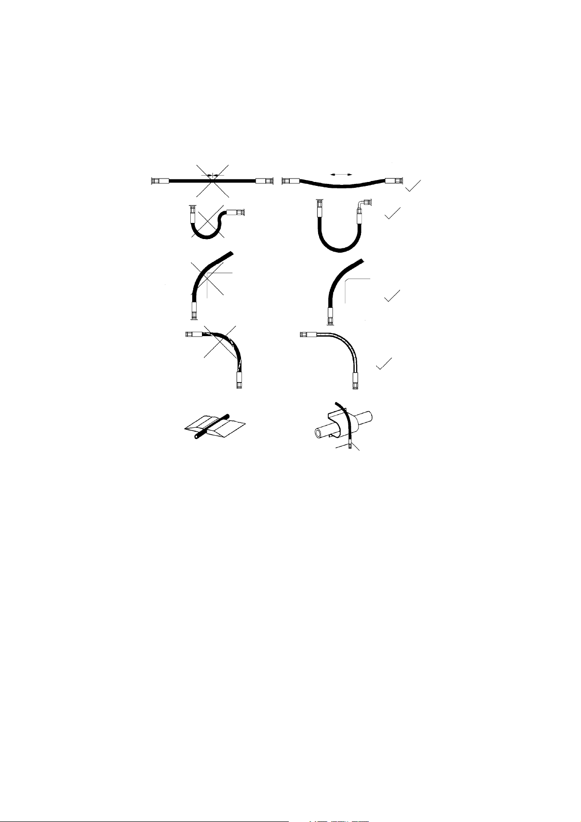
5.1 Handling of hoses
- Never exceed the permissible working pressure as stated on hose and/or literature
- avoid any tension (see figure 1) and do not hang any load onto the hose
- never exceed the minimum bend radius as resulting kink will cause failure of hose (see figure
2)
- do not allow hose to contact sharp edges or rough objects (see figure 3)
- avoid any twisting of hose (see figure 4)
- do not run over hose with any vehicle or equipment ! Hoses which are put on the surface of
sidewalk or street have to be suitably protected (see figure 5)
- do not allow hose to contact areas of high temperature such as mufflers, exhaust manifold,
heaters or burners. Protect the hose as shown in figure 6 or install it in sufficient distance
from the source of heat.
- it is not allowed to attach weights to the hoses
- make sure that no objects fall on the hoses.
5.2 Protection of the working area in case of breakdown of hoses
Hoses have to be installed or protected in such a way that dangers are prevented, if possible,
in case of breakdown of the hoses.
Danger can be caused by:
- Uncontrolled hose movement after a hose rupture caused e.g. by external influence.
- Emerging of the pressure medium under pressure.
- Inflammation of pressure medium near igniting sources
4
Page 5

Dangers can be prevented by e.g. protective coverings or shieldings
5.2.1 Do not go near leaks!
- High pressure oil easily punctures skin causing serious injury,
gangrene or death!
- If injured, seek emergency medical help! Immediate surgery is
required to remove oil!
- Do not use finger or skin to check for leaks!
- Lower load or relieve hydraulic pressure befor loosening finttings!
5.3 Storage of hoses
- Hoses are subject to a natural aging even if they are stored correctly. Therefore, their
storage and service time is limited.
When storing the hoses please observe the following:
- Store them cool, dry and dustless (eventually wrapped with plastics sheeting); prevent direct
solar radiation and UV rays; shield heat sources which are near the hoses.
- Do not use any ozone producing lamps (e.g. fluorescent light sources, mercury-vapor lamp)
or electrical devices next to the hoses.
- Hoses have to be stored freely of tension and in a horizontal position. If they are stored in
rings the smallest bending radius determined by the manufacturer must not fall below.
5.4 Marking of hoses
- The hose is marked with the manufacturer's name and quarter/year of production.
- The max. allowable pressure and month/year of production is indicated on the hose end fitting.
5.5 Inspection and replacement intervals of hoses
- After each operation the hoses have to be checked for external damages, cracks,
kinks and bubbles!
- The operator has to replace the hoses in appropriate period of times, even if there are no
visible security defects on the hoses.
- The hoses have to be replaced 10 years as from date of manufacture at the latest
(see marking on the hose)!
Hoses are subject to a natural aging even if they are stored correctly. Therefore, their storage
and service time is limited.
- Hoses have to be checked by a skilled person before the first putting into operation
of the technical device and afterwards at least once a year for their safe working
condition.
A skilled person is somebody having sufficient knowledge concerning hydraulic hoses due to his
special training and knowledge. He/she must be acquainted with the local safety working
conditions, accident prevention regulations, technical regulations and approved standards (e.g.
DIN-Standards), so that he/she is capable to estimate the safety working conditions of the
hydraulic hoses.
5
Page 6

5.6 Examples for possible defects of hoses
- Damages of the surface and the interior (e.g. chafe marks, cuts or fissures).
- Embrittlement of the surface (fissuration of the hose material).
- Deformations, which are not in accordance with the natural shape of the hoses, in pressureless
condition or under pressure or in case of bendings, e.g. separation of material layers, blister
formation, squeezing or break spots.
- Leakage points.
- Instructions for installation were not observed.
- Emerging of the hose from the end fittings.
- Damages or deformations of the end fittings which deteriorate the function and stability of the
end fittings or the connection between hose and end fitting.
- Corrosion of the end fittings or the metal inlets, which deteriorates the function and stability.
- Storage and operation periods were exceeded.
6 Application
6.1 General
General facts about the rescue rams LZR../... und LTR ./..
These rescue rams have been designed especially for rescue purposes. Their main purpose is
to open the gap created by the spreader or the multi purpose tool, because they travel farther than
the multi purpose tool.
Locked-in people can be freed by e.g. pushing away the seats or the car front, by pushing up the
steering pillar or an indented car roof.
The device is suitable for submerged operation in water up to a depth of 40m.
Before the rescue operation begins, the object to be worked upon must be stabilized.
In each country, the country-specific safety regulations must be regarded.
When working in an environment which involves a risk of explosions, do not use motor/engine
powered pumps. Instead, use hand pumps.
When operating rescue devices, wear
- protective clothing
- helmet with visor or goggles
- protective gloves.
During operation of this rescue device, parts of the object worked on with this device may break
away and endanger people standing nearby. Onlookers must be kept at a safety clearance of at
least 5m.
The device may be used in environments submerged in water to a depth of up to 40 m.
6.2 Function and performance
6.2.1 Description
The rescue rams are designed for double-acting hydraulic rams. Retraction of pistons of the
rescue rams is also effected hidraulically.
6.2.2 Connection diagram
For your better understanding the hydraulic diagram is
showing in simplified manner the cutter`s hydraulic
cylinder with control valve.
6
Page 7

6.2.3 Type LZR../...
One-stage rams for pushing with constant compressive force over the whole stroke.
6.2.4 Type LTR ../...
Telescopic rams for pushing with different compressive forces in the piston stages and low
collapsed height in comparison with the stroke.
6.2.5 Type LZR 12/550 PS
One-stage ram with supplementary operating possibilities (patented)
- for pushing, as 6.2.3
- for piercing an opening (steel up to a thickness of 6mm) when using the penetration tip at
the piston rod.
- for increasing openings by a special peeling effect which is possible because of the peeling
attachment (at the piston rod) and the guiding at the piston pipe.
6.3 Hydraulic oil supply
6.3.1 LUKAS motor/engine pump or hand pump is used for operating the devices.
6.3.2 Note
If the pump power pack comes from a manufacturer other than LUKAS, it must be ensured that
it fulfils the LUKAS specifications, as otherwise dangers may occur for which LUKAS cannot be
held liable.
6.3.3 Hoses
The connection between pump power pack and rescue ram unit is normally effected with hoses.
If pipes are to be used, please contact LUKAS.
6.4 Control of movements in operation
6.4.1 Tool with control valve (standard version)
With this version the piston rod movement is controlled by the firmly mounted star grip control
valve (see cover page item 1.1).
7 Connection of the devices
7.1 Hydraulic
Two short hoses (each 0.5 m long) are fitted to the device; they are connected with the pump power
pack via a hose pair (5 m / 10 m / 20 m, as is necessary). All hoses are colour marked and have
rapid action couplings so that they can be connected without the risk of mix-up:
HP = High pressure ——> black R = reflux ——> blue
7.2 Connection of the plug-in coupling counterparts for HP and R hoses
The device is connected to the hydraulic pump with the plug-in coupling counterparts (plug and
socket), there being no risk of mix-up.
7
Page 8

Before coupling, remove the dust protection covers and unlock the connect socket with adjusting
ring by turning it. Withdraw the sleeve and connect plug and socket while holding the sleeve in
this position. Release the sleeve and set the showglass to „red“ with the adjusting ring. Now the
parts are connected and locked. Decoupling is done in the reverse order.
Note regarding the modified release mechanism as of June 2004
When connecting the hoses, be aware of the following basic functions of the quick couplers:
X
Before coupling unlock the connect socket by turning the sleeve into position X. Retract sleeve
and connect plug and socket. Release sleeve and turn it into position Y.
Now the connection has been made and locked. Uncoupling is done in the reverse order.
Connection of the hoses is possible only, when they are depressurized.
In order to prevent contamination of the tool lines protect the couplings with delivered dust caps.
Attention!
Quick couplers partly have special functions. Therefore it is not allowed screwing them off
from the hoses or to exchange them.
Y
8 Operation
8.1 Preparatory measures
8.1.1 Initial start-up
Before initial start-up and after repairs, the device must be vented:
- Connect the device to the hydraulic pump.
- Fully open and close the device at least twice without load.
8.1.2 Inspection of operating state of the pump power pack
——> See separate Operating Instructions of the power pack (or manual pump) in question.
Note:
Before working on the pump power pack or for coupling/decoupling the hoses, make sure that the
pump power pack is switched off (electric connection) or disconnected from the mains and that
the lines are unpressurized.
8.2 Operating of the star grip 1.1
Extend device:
Rotate star shape ring 1.1 to the right hand side and hold it in this position.
Retract device:
Rotate star shape ring 1.1 to the left hand side and hold it in this position.
Load sustain function:
If released, the star shape ring 1.1 returns automatically to center position, maintaining fully the
load sustain function.
8
Page 9

8.3 Principles on rescue rams
8.3.1 LZR../... und LTR./..
Important!
When applaying the tool make sure that all tips of both the body - mounted and the piston - mounted
claw have a firm and safe grip with the load so as to avoid any point load. Lifted loads have to
be supported by suitable cribbings or other packings.
8.3.2 Use of extensions According to the regulations of DIN 14751 T3,
Where this instruction does not apply,
the extension 250 mm may be used only with
the LZR 12/300EN and as shown in the drawing.
Important!
Watch the rescue cylinder and the extension closely during the operation.
8.3.3 LZR 12/550 PS
Preparation of the wall (penetration)
To start the peeling function a hole of 60 x 60 mm
has to be made. The cylinder with penetration tip has
to be adjusted to a counterpart and the ram hydraulically
extended to create a hole in the wall.
Attention:
No person is allowed to stand behind the wall while
creating the hole in the wall.
Peeling operation
The rescue ram is placed into the hole by using the counterpart of the
peeling tip as starting point. By extending the rescue ram with the
peeling tip hydraulically an opening as far as the stroke of the cylinder
can be made. Peeling operation see picture on the left. To create a
"man hole" the peeling operation has to be made four times. The direction for each peeling operation has to be changed by 90° to create
a retangular opening.
and DIN EN 13204 (draft 6.98)
a use of extensions is not allowed.
8.3.4 Warnings
Before any operation of the rescue ram unit make sure that the extension of the piston rods with
claws does not constitue a risk to persons (involved or uninvolved) or that the piston movement
or cut-off parts jerking away cannot damage property.
Important!
The claws must be jammed tight even in case of long strokes. Avoid slipping through proper
application!
Do not use the piston for carrying the device!
Use of stroke extension pieces is not allowed! (exept LZR 12/300EN)
9
Page 10

9 Dismantling of the device / Stop after operation
9.1 Rescue ram
After each use retract the piston rod until it protrudes only a few mm. This hydraulically and
mechanically relaxes the device.
9.2 Hydraulic Power Package
As soon as the rescue work is finished, the power package must be switched off, and the
hoses must be disconnected from the ram.
Remark: While being stored, the piston of the ram might advance slightly due to changes of the
ambient temperature. The reason for the piston movement is that the oil volume in the piston chamber
and the rod chamber would expand its volume differently when exposed to temperature changes.
Therefore, the storage compartments for rescue rams (e. g. inside the truck) must be built in such
a way that the piston may advance by approx. 30 mm without damaging the compartment wall.
10 Maintenance
10.1 Rescue ram
After each operation a visual check has to be accomplished, at least once per annum. Every 3
years or if there are doubts about security or reliability, an additional funtional test has to be
accomplished. (clean them first if necessary)
Visual inspection
• Ram and piston rod without damages and deformations.
• Claws in the right position and jammed tight,
• Claws in a good condition (breaks),
• No leakages,
• Easy operation of the star grip,
• Handle existing and fast,
• Identification plate and position plates legible,
• Quick connect couplings can be connected easily,
• Dust covers in the right position.
Hoses
• Check according safety instructions for hoses (see item 5)
• Check for oil leakage
Function testing
• Piston stroke can be retracted and extended to the full length (see technical data 13),
• Perfect opening and closing with star grip standard version.
11 Repairs
11.1 General
Servicing must be carried out only by the device manufacturer or by personnel trained by the
manufacturer or the authorised LUKAS dealers.
For replacement on all components, use only genuine LUKAS spare parts as specified in the spare
parts list, as here possibly required special tools, mounting information, safety aspects, testing
must absolutely be taken into account. See Section 4.
Protection of the device against hydraulic overload
If the short hoses of the tool are not connected with the power pack, pressure can be built up
unintentionally in the cylinder due to temperature increase. Therefore, the return hose (0,5m / blue)
of the tool is equipped with a safety coupling (quick connect plug, colour yellow). Unintentional
overpressure (approx. 1.5 MPa) is released through this plug: oil comes out.
10
Page 11

Should the tool have been equipped with couplers of different brand which do not have this safety
function, overpressure would be released through another safety valve (adjusted to approx. 30
MPa) included with the control valve block. In this case oil spill would be observed in the star grip
area.
As soon as sufficient pressure is released the valve becomes tight again. Should further constant
leakage ocur, please have the tool inspected by LUKAS personnel.
On repair, protective clothing is mandatory (see Section 1), as the cutter units can be pressurized
also in unoperated state.
11.2 Preventive maintenance
11.2.1 Maintenance advice
To protect the device against external corrosion clean its surface from time to time and slightly
grease it with oil.
11.2.2 Maintenance and service work
For maintenance work, LUKAS offers a service kit as appropriate equipment.
11.2.3 Function and load test
If there is any doubt as to the safety and reliability of the equpiment, carry out an additional function
and load test. For this purpose, LUKAS offers a test kit as appropriate equipment.
11.2.4 Change of hydraulic oil
- after 200 uses, latest after 2 years, the hydraulic oil has to be changed.
- in any case if the oil of the pump (motor / hand pump) which belongs to the unit is changed.
By changing the used oil, it should be avoided that the new oil is polluted by the used oil of the
rescue tool.
Procedure:
The rescue tool is in closed (retracted) position • Change of oil has to be effected at the pump.
Screw off the return hose at the pump:
- in case of hose connection: screw off the connecting piece of the blue return hose.
- in case of quick connect couplings: screw off totally the coupling nut of the quick connect
coupling of the blue return hose.
Extend pump with tool slowly • Collect the used oil at the piston rod side in a separate tank and
dispose of the used oil (as the used oil of the pump) • Do not operate the pump any longer.
Connect the return hose again to the pump:
- Tighten the coupling nut of the quick connect coupling according to 11.3.3,
- Screw the hose nipple into the valve bloc with MA = 45 Nm,
- Ventilate the tool according to 8.1.1.
11.3 Repairs
11.3.1 Oil spill out of the control valve handle
Pressure or return hose are not tightened properly.
Procedure:
Loosen the 2 allen screws (SW5) inside the handle sleeve and remove them together with the short
plastic isolation sleeves. Pull handle sleeve backwards until the hose connection points become
visible and retighten the retaining nut. Change hose connection sealing rings if necessary. Place
handle sleeve again and tighten it with the 2 allen screws. Make sure that the plastic isolation
sleeves are placed properly on the allen screws before mounting.
11
Page 12

11.3.2 Set of identification stickers
All damaged or illegible indentification stickers (Safety instructions, type label a.s.o) have to be
replaced.
Procedure:
Remove damaged stickers and clean surface with acetone • Put on new stickers.
11.3.3 Quick couplers
Quick couplers on the 0,5m hoses have to be replaced when
- external damage can be observed,
- the locking sleeve doesn´work any more,
- oil spill occurs even when the coupling is properly connected.
Remark: Faulty couplers have to be changed completely against genuine LUKAS spares, i.e. it
is not permissible to make any repair work.
The retaining nut on the hoses has to be tightened with a torque of MA = 45 Nm
12 Troubleshooting
Trouble Check Cause Remedy
Hoses cannot be Pressurized Relieve pump pressure
coupled
On actuating pistons Hoses correctly Air in the hydraulic Thoroughly vent pump
move slowly or by connected power system unit: see 8.1.1
jerks pack operating
No pressure build-up Not enough oil in hand Refill oil and vent the
Star grip doesn't return Return spring is Ask authorized dealer or
to middle position when damaged or return LUKAS themselves
released mechanism is dirty
Oil leakage out of Untightness, eventually Replace hoses
hoses or hose fittings damages
Surface of hydraulic Contact with Change hoses
hoses is dissolved agressive fluids
Leakages on the Seal defective piston Replacement of seals
piston rod rod by authorized dealer or
resp. motor pump. system (see operating
Vent pumpe after instruction 8.1.1)
changing oil
LUKAS themselves
If the defects cannot be repaired, contact an authorised LUKAS dealer or the LUKAS service department.
The address:
LUKAS Hydraulik GmbH, Weinstraße 39, D-91058 Erlangen, Pf 2560, D-91013 Erlangen, service phone
09131/698 348; fax 09131/698 353.
12
Page 13

13 Technical data
Type LZR12/300EN LZR12/500EN LZR12/700EN LZR12/550PS LZR19/325
Ref. no. 84150/6101 84150/6102 84150/6103 84150/6088 84150/6092
Compressive force (kN)
(in all operating ranges)
Piston stroke (mm) 300 500 700 550 325
Length retracted (mm) 450 680 900 800 460
Length extended (mm) 750 1180 1600 1350 785
Dimensions wxh (mm) 171 x 82 192 x 82 100 x 200
Weight (incl. oil filling) (kg) 13.0 18.0 24.0 21.8 14.3
Operating pressure (MPa) 63*
Max permissible pressure see identification plate
Usable oil quantity (l)
DIN 14751
1
0.5 0.8 1.2 0.7 0.8
RZ1.1 2001 RZ1.2 2001 RZ1.3 2001
TP18 (TÜV) TP18 (TÜV) TP18 (TÜV)
European Norm HR 01-2000 HR 02-2000 HR 03-2000
prEN 13204 (April 98) (TÜV) (TÜV) (TÜV)
USA NFPA 1936
Technical Report No. 70000275-1
(TÜV-Produkt Service)
Type LTR6/570 LTR3,5/820EN LTR12/575EN LTR12/875EN
Ref. no. 84150/6089 84150/6106 84150/6056 84150/6055
Compressive force piston 1 (kN) 190 240
Compressive force piston 2 (kN) 60 120
Compressive force piston 3 (kN) 35
Stroke piston 1 (mm) 325 295 445
Stroke piston 2 (mm) 245 280 430
Stroke piston 3 (mm) 245
Piston stroke total (mm) 570 820 575 875
Length retracted (mm) 460 475 625
Length extended (mm) 1030 1295 1050 1500
Dimensions w x h (mm) 110 x 200 112 x 210
Weight (incl. oil filling) (kg) 16.9 17.7 16.7 20.9
Operating pressure (MPa) max. 63*
Max. permissible pressure see identification plate
Usable oil quantity (l)
DIN 14751
1
1.0 1.5 1.4 2.2
RZ10-93- RZ 03-01- RZ 01-01- RZ 02-01-
TP18 (TÜV) TP18 (TÜV) TP18 (TÜV) TP18 (TÜV)
European Norm HR 06-2001 HR 07-2001
prEN 13204 (April 98) (TÜV) (TÜV)
USA. NFPA 1936 Technical Report No. 70022561/5 (TÜV-Produkt Service)
* 1MPa = 10 bar;
1
Necessary oil quantity in the hydraulic power pack for operating the tool
(Difference in quantity piston / rod side)
120 190
13
Page 14

13.1 Peeling with LZR 12/550PS
max. thickness of steel (mm) 6
max. opening (mm x mm) 550 x 550
13.2 Oil recommendations
For LUKAS hydraulic devices, use mineral oil in accordance with DIN 51 524 and others
Range of oil temperature Viscosity rating Remarks
A - 24 ... + 30 °C HL 5
B - 18 ... + 50 °C HLP 10
C - 8 ... + 75 °C HLP 22
D + 5 ... + 80 °C HLP 32
E - 8 ... + 70 °C HF - E 15 biodegradable
Recommended viscosity range: 10 ... 200 mm²/s, delivered with HLP 22 to DIN 51 524
13.3 LUKAS Hoses
Bending radius Rmin = 38 mm
Burst resistance safety factor: burst pressure / max. operating pressure min. 4 : 1
Temperature resistance - 40°C ... + 100°C
Operating medium mineral oil according to DIN 51524
13.4 Others
Working temperature -20 ... +55°C
Ambient temperature (power pack in operation) -24 ... +45°C
Storage temperature (power pack not in operation) -30 ... +60°C
LUKAS Hydraulik GmbH
A Unit of IDEX Corporation
Weinstraße 39, D-91058 Erlangen
Postfach 2560, D-91013 Erlangen
Telefon (09131) 698-0 • Telefax (09131) 698-394
e-mail: info@lukas.de
Rescue_Rams_LZR_LTR_BA_GB_0406.p65 subject to revision
14
© Copyright 2002 LUKAS Hydraulik GmbH
 Loading...