

Operating Instructions
Recycling system
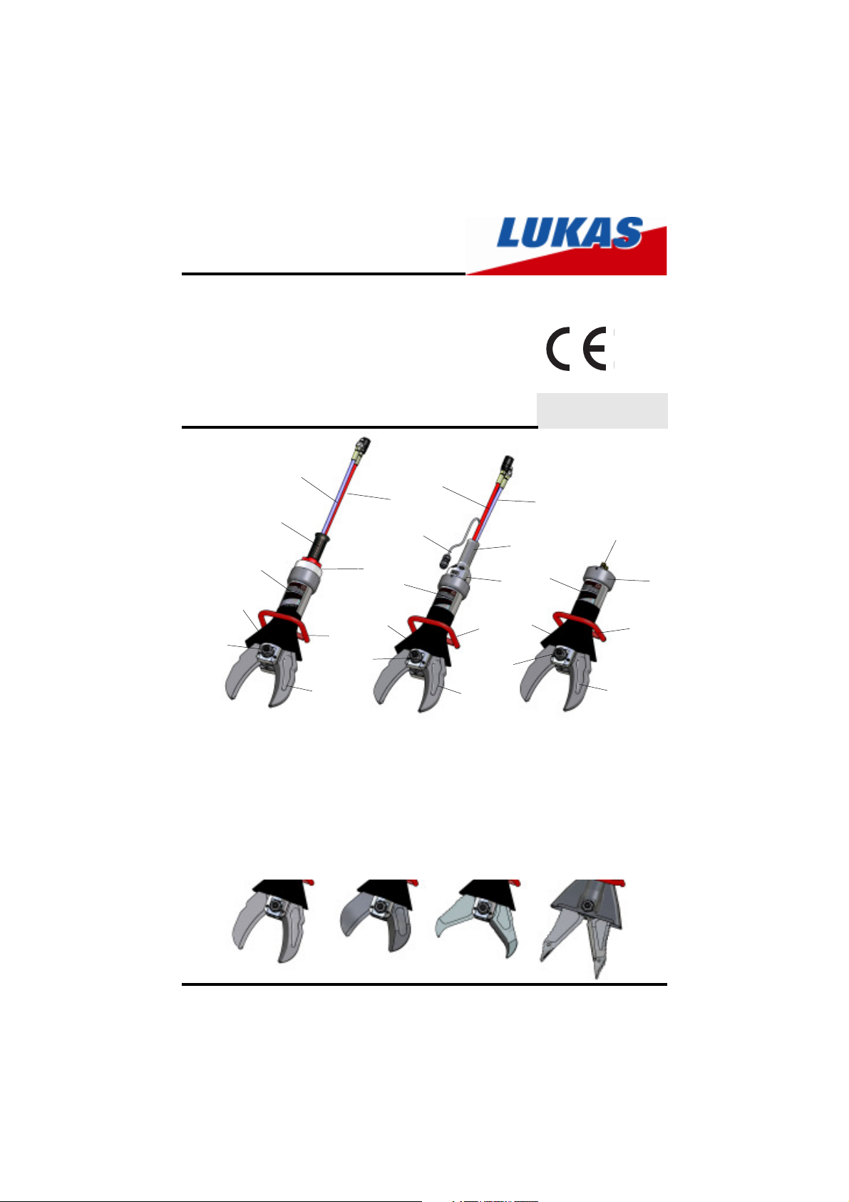
Cutter
LSI 501, LSI 511, LSI 530, LSI 55
9
11
6
7
5
4
with 4/3-way-valve
1 4/3-way-valve with star grip
2 Electric control unit
3 Cylinder bottom
4 Cutter blades
5 Central bolt with self-locking nut
and lubricating nipple
6 Hydraulic cylinder
7 Hand guard
1
12
7
5
with electric controls
8
8
13
6
12
4
8 Hose line red: pressure
with quick-connect socket
9 Hose line blue: return
with quick-connect plug
10 Connecting nipple
11 Handhold
12 Handgriff
13 Power connection
84150/1490-85 GB
Issue 07.2006
9
11
6
2
7
5
with cylinder bottom
10
3
12
4
LSI501
LSI511
LSI530
1
LSI55

Content Page
1 Correct use of the device 3
2 Organisational measures 3
3 General safety instructions 4
4 Maintenance and servicing instructions 5
5 Safety instructions for hose lines 6
6 Functions and performance 8
7 Connecting the device 9
8 Operation 11
9 Cutting 13
10 Dismantling of the device / switching off after use 14
11 Maintenance 14
12 Repairs 15
13 Troubleshooting 19
14 Technical data 20
2

1 Correct use of the device
1.1. The device has been constructed according to the latest technology and the
recognised safety regulations. However, danger to life or limb can arise for the operator
or third parties occur during use or the device and other items can be damaged.
1.2. Only use the device in perfect condition and according to the instructions, safely
and safety conscious! Immediately repair (or arrange repair of) malefunctions which
can affect safety!
1.3 The cutter is mainly used in recycling and demolition works. The cutting tool is
intended for long-term industrial use. It is designed for cutting steel, sufficiently hard
non-ferrous metals, steel sheets and cables. Depending on the type of use, devices
are available with different blade shapes.
Typical cutting performance is listed under „Technical Data“.
1.4 The following must not be cut:
- energised cables
- Pipes with pressurised gas or fluids
- Pre-tensioned and hardened parts such as springs, struts, steering columns
and millings
- Mixed materials, e.g. steel/concrete
1.5 The device (without electrical controls) is suitable for underwater use up to 40 m.
1.6 Devices with cylinder bottom are intended for externally controlled processes.
They are mainly used on robots, cranes or other manipulators.
1.7 The manufacturer / supplier is not liable for damage resulting from incorrect use.
The user alone bears the risk. Correct use also includes observing the operating
instructions and the inspection and maintenance conditions.
2 Organisational measures
2.1 Always store the operating instructions to hand at the location where the device
is used.
2.2 In addition to the operating instructions, generally applicable statutory and other
binding regulations regarding accident prevention and environmental protection must
be observed and applied.
This also includes the wearing of work or protective clothing, helmet with visor or
protective goggles, gloves and, if necessary, ear protectors.
2.3 The device must only be used by a properly trained person, familiar with safety
regulations, as otherwise there is a danger of injury.
2.4 Comply with all safety and risk notices on the device! Keep all safety and risk
notices legible.
2.5 Do not change the device, add or change anything on the device without the
manufacturer’s consent. This is also the case for fitting and adjusting safety equipment
and valves.
3

2.6 The operating pressure marked on the device must not be exceeded.
2.7 Only original LUKAS parts and original LUKAS accessories and system
components should be used for repairs.
2.8 Prescribed and named deadlines for tests/inspections as stated in the operating
instructions must be observed.
2.9 Properly dispose of all packaging materials and removed parts.
3 General safety instructions
3.1 In the event of a malfunction, immediately shut off and secure the device. Repair
(arrange repair) immediately.
3.2 Before start-up / running and during operation, ensure that nobody can be
endangered by the running device. This also means checking the device for loose
connections.
3.3 Do never grip between the blades and take care that body parts (e. g. hair, fingers)
or clothing are never insert between openly visible movable parts.
3.4 Only touch the cutting parts with protective gloves as cutting edges are very sharp.
3.5 Please note that cut material can fall or catapult away as a result of its sudden
removal and suitable protective measures should be taken.
3.6 When working, you must ensure there is sufficient illumination.
3.7 After each use of the device, check for external damage and deficiencies.
Immediately report changes detected (including changes to its operation) to the
appropriate office. If necessary, immediately shut off and secure the device. Check
all hydraulic and electrical lines, hoses and threaded connections for leakage and
check for external damage and immediately repair. Leaking oil can lead to injuries
and fires. Damaged electrical lines can lead to short circuits and electric shocks
which can result in death.
3.8 All types of work which affect the safety and stability of the device are prohibited.
Damage can also occur as a result of the device falling over and/or persons can be
injured by the falling device. Take care if you use a balancer that in case of a
malfunction there is also the possibility that the device could fall down.
3.9 You must check that all safety equipment is complete and in perfect condition:
- Labels and notices (safety notices)
- Safety covers (e.g. hand guard, etc.) are on and in perfect condition.
3.10 When working near energised components and lines, suitable measures
should be taken to avoid current transfers or high voltage transfers to the device.
3.11 The device is filled with hydraulic fluid. These hydraulic fluids can affect your
health if drunk or if their fumes are inhaled. Direct skin contact should be avoided for
this reason. When working with hydraulic fluids, please be aware that they can have
a negative impact on biological systems.
4

3.12 The generation of an electrostatic charge producing sparks as a possible
consequence should be avoided when working with the device.
3.13 When working with or storing the device, ensure that the function and safety of
the device are not affected by large external temperature effects and that it is not
damaged. Please note that the device can heat up as a result of prolonged use.
3.14 Safety equipment must never be disconnected.
3.15 Never work when overtired or inebriated.
3.16 Before transporting the device, always check that the accessories are secure.
3.17 Make sure that you do not caught by hose lines and cables and trip when using
or transporting the device.
4 Maintenance and servicing instructions
4.1 In order to carry out maintenance and service work, equipment suitable for the
work is required. Only staff with specific knowledge and experience in hydraulics may
work on the device!
4.2 Clean oil and all dirt from device and, in particular, connections and screw joints
before starting working. Do not use an aggressive detergents. Use a fibre-free cloth
and ensure thorough cleanliness, especially when rebuilding.
4.3 When dismantling the device, ensure that all escaping hydraulic fluid is collected,
that it does not enter the soil and that it is disposed of in accordance with existing
provisions.
4.4 Always tighten loosened screws and threaded connections when assembling
and observe the prescribed torque.
4.5 Work on electrical devices may only be undertaken by a specialist electrician or
by trained persons under the supervision of a specialist electrician corresponding to
the electrical technical regulations.
4.6 Aggressive media (acids, soaps, solvents, steam) can damage the device. If the
device has to be operated in such an environment in exceptional cases, or if it comes
into contact with such items, the entire device must be thoroughly cleaned. Moreover,
a check according to No. 3.7 above must be undertaken.
4.7 LSI tools must be inspected at regular intervals for dirt in the hand guard, notably
when working overhead. This dirt must immediately be removed (see also
„Maintenance).
4.8 The electrical equipment of the device must regularly be inspected/checked.
Deficiencies, such as loose connections and braised cables, must immediately be
remedied.
5
5 Safety instructions for hose lines
A T T E N T I O N !
- The hoses must never come into contact with brake fluid.
- After coming to contact with the following fluids, the hoses must immediately be
cleaned:
• acids, soaps, solutions / diluted
• alcohol and fuels
• battery acids and ATF
• phosphate esters
It is also essential that the hose lines are checked for damage after cleaning. The
hose lines must be replaced if necessary.
1
2
3
4
5
picture 2
6
6
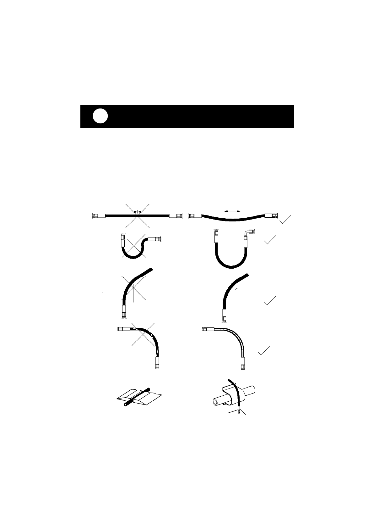
5.1 Handling instructions for hose lines
- The defined operating pressure must not be exceeded.
- The hoses must not be subjected to tension and torsion (see picture 2, fig. 1).
- The hose line must not be bent (see picture 2, fig. 2).
- Do not pull or lay hoses across edges (see picture 2, fig. 3).
- Do not connect twisted hoses (see picture 2, fig. 4).
- Never drive a vehicle over the hoses. Loose hose lines laid on roads and paths
must be protected against damage, e.g. with hose bridges (see picture 2, fig. 5).
- In the event of high temperatures occurring externally, the hose lines must either
be fitted a sufficient distance from the heat-emitting components or protected by
suitable measures (shields) (see picture 2, fig. 6).
- Weights must not be suspended on the hose lines.
- Objects must not be allowed to fall onto the hose lines.
5.2 Securing the environment in the event of a hose failing
Hose lines must be laid or secured such that risk of the hose failing is avoided.
Danger can occur as a result of:
- the hose moving back and forth after tearing, e.g. through external influence,
- the pressure medium escaping under pressure,
- escaping pressure medium igniting close to a igniting source.
The danger can be avoided, for example, with protective coverings or shields.
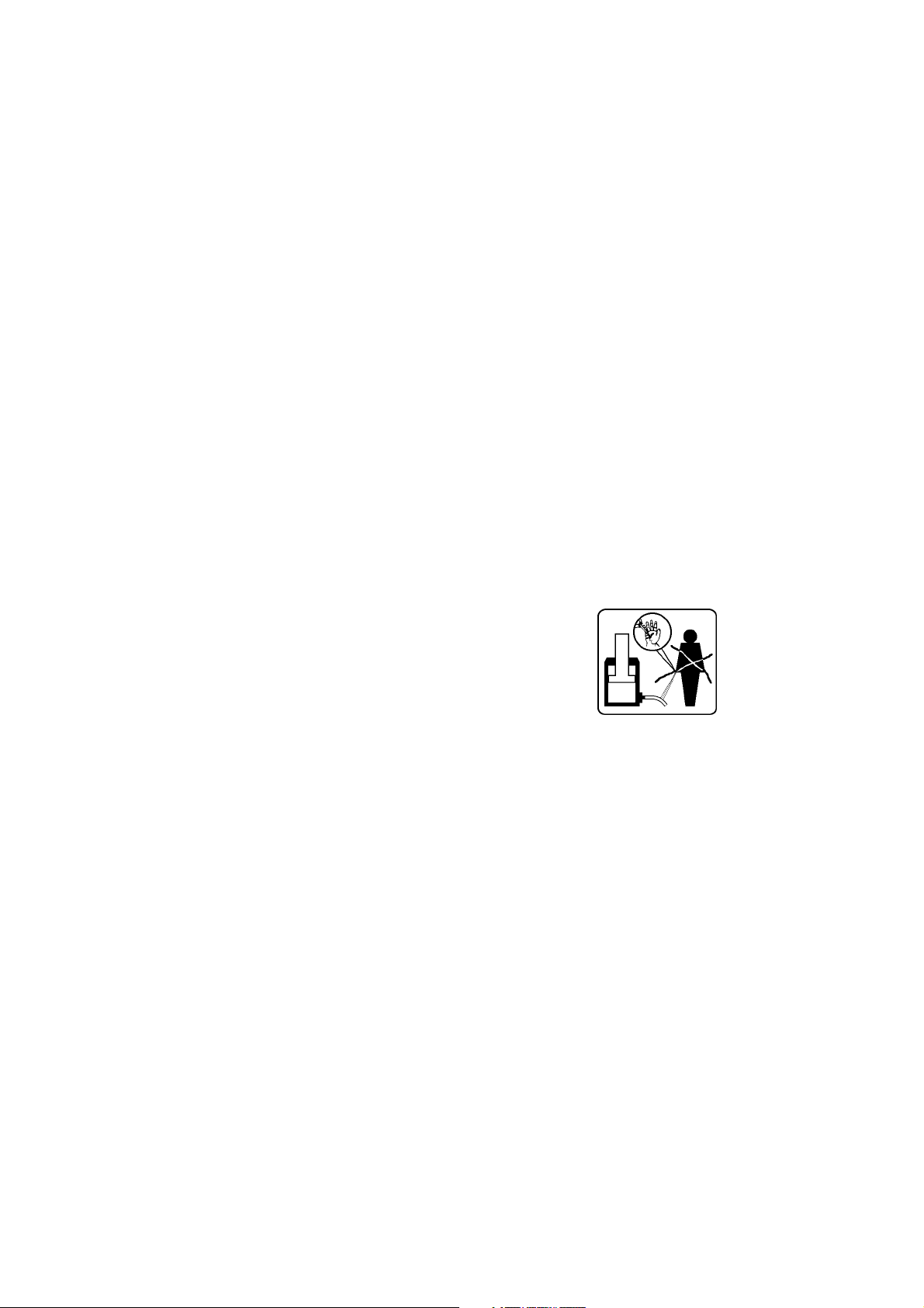
5.2.1 Beware of hairline tears
- Escaping high-pressure oil can cause serious injuries
when impinge to the skin.
- In the event of an injury, immediately consult a doctor!
- Oil must immediately be cleaned from the wound.
- Do not search for leaks using a finger.
- Depressurise the hydraulic system before loosening
connections.
5.3 Storing hose lines
- Hose lines are subject to natural aging even when stores correctly and with
permissible loads. As a result, their storage time and period of use are limited.
When storing hose lines, the following should be observed:
- Store cool, dry and dust-free (ideally, wrapped in plastic); avoid direct sunlight or
UV radiation; shield from nearby sources of heat.
- Do not use ozone-forming lights (e.g. fluorescent lights, mercury vapour lamps)
or electrical devices in the immediate surroundings
- Hose lines must be stored de-energised and in a lying position. If storing in
rings, the smallest bend radius as recommended by the manufacturer, must not
be exceeded.
5.4 Labelling the hose lines
- The hose is labelled with manufacturer and operating pressure.
- The maximum permissible operating pressure and month./year of manufacture
are labelled at the pressurised neck.
7

5.5 Periods for checking and replacing hose lines
- Check the hose lines for external damage, tears, bends and inflating after
every use.
- The operator must ensure that hose lines are replaced at reasonable intervals,
even if no safety deficiencies can be detected on the hose.
- The hose line must be replaced 10 years after manufacture at the latest (see
label)!
- Hose lines must be checked before first start-up of the technical equipment
and then at least once a year to ensure a safe working condition by a properly
trained person. For examples of possible deficiencies, see 5.6 below.
5.6 Examples of possible deficiencies to hose lines
- Damage to the external layer to the insert (e.g. chafing, cuts or tears).
- External layer becoming brittle (tears to the hose material).
- Deformations not corresponding to the natural shape of the hose when under
pressure or depressurised, or when bent, e.g. separation of layers, bubbles,
squashed areas, bends.
- Leaks.
- Installation requirements not observed.
- Hose leaves the fittings.
- Damage or deformation to the fittings which alleviates the function and stability of
the fittings or the hose – fittings connection.
- Corroded fittings or metal inserts, which alleviates the stability.
- Storage times and period of use exceeded.
6 Functions and performance
6.1 Description
The device is designed such that a hydraulic piston is connected across two equal,
opposing, symmetrical blades via mechanical joints and so cuts materials. The
blades are designed for the application in terms of their geometry so that sliding of
the material being cut is avoided as much as possible.
6.2 Controlling the working movements
6.2.1 LSI cutter with 4/3-way valve
The movement of the blades is controlled by the star grip on the fitted valve (see first page
pos. 1).
The circuit diagram is simplified here to make
the function comprehensible
(hydraulic cylinder (A) + 4/3-way valve (B).
6.2.2 LSI cutter with electrical controls
The movement of the blades is controlled by the electric control unit on the fitted
valve (see first page pos. 2).
The circuit diagram is simplified here to make
the function comprehensible
(hydraulic cylinder (A) + 4/3-way valve (B).
8
cutting
open
cutting
open

6.2.3 LSI cutter with cylinder bottom
The cutter with cylinder bottom is controlled with pressure to the correspondingly
labelled connection nipple (see first page pos. 10). Control is not directly on the
tool, but through external controls.
The blades are opened with pressure to connector
nipple „B“.
The blades are closed with pressure to connector
nipple „A“.
cutting
open
6.3 Hydraulic power
Only LUKAS hydraulic aggregate should be used to operate the device. If the
pump aggregate is made by another manufacturer, please ensure that it is
designed in accordance with LUKAS specifications, as otherwise potential
dangers can occur, for which LUKAS cannot be responsible. If in doubt, contact
the authorised LUKAS dealer or LUKAS direct.
Ensure that the permissible operating pressure for LUKAS LSI devices of 50
MPa (= 500 bar) is not exceeded without consulting LUKAS.
6.4 Hose lines
The connection between pump aggregate and cutting tool is normally via LUKAS
hose lines.
When connecting a piping, contact LUKAS directly in advance.
7 Connecting the device
7.1 Hydraulical
7.1.1 LSI cutter with 4/3-way valve or with electrical controls
The device has two hose lines; these are connected with the pump aggregate via
a pair of hoses (5 m or 10 m as required). All hose lines are colour marked and
fitted with quick connectors so that they cannot be mistaken:
HP = High pressure ——>red R = Return ——>blue
7.1.2 LSI cutter with cylinder bottom
The device has two connectors for hose lines; these will be connected with the
pump aggregate via a pair of hoses (5 m or 10 m as required) (not included in the
delivery). The hose lines are directly screwed to the cylinder bottom and tightened
with a torque of 45Nm. Ensure that the high pressure hose are screwed into
connection „A“ and the return hose is screwed to connection „B“!
7.2 Connection of the plug-in coupling counterparts for HP and R hoses
The device is connected to the hydraulic pump with the plug in coupling conterparts
(plug and socket), there being no risk of mix-up.
When connecting the hoses, be aware of the following basic functions of the quick
couplers:
X
X
9
Y

Before connecting, withdraw and hold the locking socket (position X). Connect the nipple
and socket and release the locking socket. Then turn the locking cover to position Y.
The connection has now been made and secured. Decoupling is carried out in reverse.
It is only possible to connect the device if the hoses are depressurised.
The supplied dust covers are used to protect against dust.
Attention!
The quick couplings currently have a special function therefore must not be unscrewed
from the hose lines and/or replaced!
7.3 Electrical (only cutters with electric controls)
The device has an approx,. 0.5 m electrical cable with a plug. This plug is connected
with the coupling of the electrical power cable and in parallel with the hose line pair
from the pump engine.
7.4 Mechanical (only cutters with cylinder bottom)
When using the cutter in a manipulator, important principles must be observed in
order to exclude danger to life and limb and to the device:
- The device must be freely rotatable around its long axis (possible through axis
on the robot or corresponding rotor hub / LUKAS accessories) for vertical
positioning to the cut material.
- The addition of protective covers and/or measures for switch securing (e.g.
safety light barrier) must be ensured.
Important!
In any case, installation must be agreed technically and in terms of safety with LUKAS!
7.5 Mechanical fixing on a balancer from the LUKAS accessories
(only cutters with 4/3-way valve or electric controls)
First setup the weight of the cutter on the
green swivel (see arrow on the picture left)
on the reverse of the balancer, this
guarantees that the cutter will remain
hanging at any desired height.
Fix the balancer to the intended suspension
(e. g. arm hook) by using the attached hook
(see picture right, pos. 1). 1
10

Then fix the LSI cutter to the swivel hanger (see
picture left).
Note: The device cannot be clamped tighter in
2
The swivel hanger has 2 holes in order to equalise
differences in center of gravity (see picture left, pos.
2) by fixing the clevis into the second hole.
The LSI cutter should now be hanging
vertically aligned to the steel cable (see
picture right).
the hanger! This is because the cutter is
pivoted in the swivel hanger.
3
Catch:
extraction
locked
Catch:
extraction
unlocked
Unlock the balancer by pulling out the
spring bolt (see picture left, pos. 3) and
turning it counterclockwise to the second, slightly higher positioned catch
and release the spring bolt to snap in.
8 Operation
8.1 Initial operation
Before first starting up, check the device for external, apparent damages and deficiencies!
Check all lines, hoses and screwed connections for leakages and external damages.
Before connecting the LSI-cutter, check the pump intended for use (see the separate
operating instructions for the pump).
Before the first starting up and after repairs, the device must be ventilated:
- Connect device to the hydraulic pump (see „Connecting the device“)
- Fully open the device twice without load until the blades can no longer move, then
immediately switch to idle and immediately close to approx. 2 mm.
11

8.2 Operating the 4/3-way valve with the star grip
Open device (extend):
Turn the star grip clockwise and hold in this position until the blades reach the desired
opening width.
Do not hold the star grip in this position if the blades have already reached their
maximum position.
Close device (retract):
Turn the star grip counterclockwise and hold in this position until the blades reach the
desired opening width or until the blades are closed completely.
Do not hold the star grip in this position if the blades are already fully closed.
Load holding function:
After release, the star grip automatically returns to the middle position with the full
guarantee of the load holding function.
8.3 Operating the electric controls
Open device (extend):
Press the green marked button until the blades reach the desired opening width.
Do not hold the green button down if the blades have already reached their maximum
position.
Close device (retract):
Press the red marked button until the blades reach the desired opening width.
Do not hold the red button down if the blades have already reached their maximum
position.
Load holding function:
After releasing the button, the blades remain in the selected position with the full
guarantee of the load holding function.
Note: Nothing happens if both buttons are pressed simultaneously (blades do
not move).
8.4 Operating with the cylinder bottom
To operate an LSI cutter with cylinder bottom, the controls are not directly on the device,
but instead are external. Please be attend to the separate operating instructions for the
controls you intended to use
Open device (extend):
The blades open with pressure via connection „B“.
Close device (retract):
The blades close with pressure via connection „A“.
The following must be observed because of the external controls:
If persons are working close to the device while it is in operation, the necessary steps
for securing the operating area must be taken (e.g. protective equipment, automatic
safety off (e.g. „safety light barriers“) or manual „Emergency Stop“-switches).
12

9 Cutting
9.1 Safety instructions
- Woldwide all national safety guidelines must be observed and complied.
- If there is a explosion risk, do not use motor pumps because of sparks. In such
cases, manual pumps must be used.
When working with the cutter, you must wear:
- work or protective clothing,
- Helmet with visor or goggles,
- Gloves
Before using the cutter, ensure that the movement of the blades does not represent a
danger to persons or objects as a result of blade movement or catapulted cut materials.
It is strictly forbidden to grip between the blades!
The following must not be cut:
- energised cables
- Lines with pressurised gas or fluid
- Pre-stressed and hardened components (such as springs, spring steel,
steering columns, rollers)
- Composite materials (steel/concrete)
9.2 Cutting procedure
The blades must be applied at right angles
to the object to be cut. Higher cutting
performance is achieved if the cutting is
as close as possible to the blade fulcrum.
When cutting, the gap between the blade
tips must not exceed 3 mm (Risk of blade
fracture).
right false
9.2.1 Attention!
When cutting with curved blades, on the blade tips the full cutting performance must
not be utilized. Cutting in profiles up to 2 mm thickness is permitted.
9.3 Spreading procedure (only LSI 55)
Use front region of the tips only for enlaging a gap.
Grip area to small, tips
may break away
Tips grip securely
13
Use tips only, do not
damage the arms

10 Dismantling the device / switching off after use
10.1 Cutter
After end of working, the blades should be closed till a few mm of tip distance. This
releases the entire device in terms of the hydraulics and mechanically.
10.2 Hydraulic aggregate
After end of working, the engine must be shut down.
10.3 Hose lines
First disconnect the high pressure hose (red), then the return hose (blue) as described
under 7.2. Attach the dust caps to the plug connections.
10.4 Electric cables
The electric cables should be disconnected in case of longer periods between uses.
11 Maintenance
After each operartion and after the end of the shift respectively, a sight check must be
carried out, at least once a year. A function test must be accomplished every 500
operating hours or if there are doubts about the safety or reliability (clean first if dirty).
Sight check
Blades
• Cutting edges free from nicks and deformation,
• Distance of blades from each other in transverse direction < 4 mm for LSI 501 and
LSI 530, and < 3 mm for LSI 511 and LSI 55 (otherwise danger of breakage)
• Cutting edges cross contactless,
• Blades free of cracks
• Dirt in the protective hose (this dirt must immediately be removed)
Cutter
• General impermeability (leakages)),
• Mobility of the star grip,
• Handle in existent and fixed,
• Check torque of the central bolt (see picture in chapter 12.3.1)
MA = torque, see „Technical data“.
Hoses
• Check according to safety instructions for hose lines (see chapter 5),
• Check oil loss.
Function test
• Opens and closes properly using the star grip, electric controls or external controls
(depending on the type of controls).
• Check device for maximum nominal load using a manometer (available as a LUKAS
accessory).
The inspection value specifications are included under chapter „Technical data“.
14

12 Repairs
12.1 General
Servicing should only be carried out by the manufacturer of by staff trained by the
manufacturer and by authorised LUKAS dealers.
Only components, which are available as original LUKAS spare parts, may be
exchanged, because possibly there must be observed necessary special tools,
assembly instructions, safety aspects or tests. Therefore use only original LUKAS
spare parts.
Overpressure safety of the cutters (when not connected)
Undesired pressure could be charged in the device as a result of incorrect connections
and temperature increases. Therefore the blue return hose has a safety coupling (quick
connect plug, coloured yellow). Undesired overpressure (approx. 1.5 MPa) is
automatically released via this plug: oil escapes as well, this is not a malefunction.
If foreign couplings are used, which do not have this function, an overpressure safety
element (opens at 30 MPa) in the cutter valve will take care for pressure equalization.
Oil escapes in the area of the star grip. After the pressure has decreased, the valve is
leak-proof again.
If the valve is permanently leaking, the device must be checked by LUKAS.
12.2 Preventative service
12.2.1 Routine checks
The torque of the central bolt must be checked regularly.
For torques, see the chapter „Technical data“.
Damaged blades can be maintained by sharpening to a total of 0.5 mm. Please ensure
that the internal cutting edges are coplanar.
The central bolt must be lubricated once a day with LUKAS special grease.
A
B
The lubrication nipple (A) is directly in the
central bolt on the side of the self-locking
nut (B).
Lubricate the cutter with a grease gun with
LUKAS special grease as shown in the
picture right.
Excess grease on the lubrication nipple
(see left) after lubrication should be removed
and disposed of professional.
15

Attention!
When working with upturned blades, in particular, please ensure that no coarse
fragments reaches the mechanical parts under the hand guard of the device. Moveable
parts of the device could be blocked as a result and even be destroyed.
The device must be checked for dirt and impurities in the mechanical part after each
of such applications, and cleaned if necessary.
illustration 1
Unscrew handle and pull back the hand guard according to illustration 1.
illustration 2
Clean dirt and shards from mechanical parts as shown in Illustration 2 and blow
out with compressed air carefully.
If the hand guard tabs to the blades are considerably worn or torn, the entire hand
guard must be replaced.
12.2.2 Main checks
The mechanical transfer elements on the device are subject to very high
mechanical stresses and therefore they must be checked after 500 operating
hours at latest. Thereby, appearances of attrition can be detected early so that
breakages can be avoided by timely replacement of these worn parts.
Perfect parts can be reassembled after careful lubrication with LUKAS special
grease.
Parts with limited wear (fretting marks) can be refurbished by polishing and reassembled
after careful lubrication with the corresponding grease.
If there are heavier traces of wear, the damaged parts must be replaced (in pairs).
At these intervals, it is essential to check the blades for crack. A special crack test
kit is available.
From time to time the cutter must be cleaned and lubricated with oil to protect it
against external corrosion.
16

12.2.3 Function and load test
If there are doubts about the safety and reliability, an additional function and load
test must be carried out. For that purpose LUKAS offers a test equipment.
12.2.4 Changing the hydraulic oil
- Change the hydraulic oil after approx. 500 operating hours, but after 2 yeas at latest;
- Whenever the oil of the appropriated pump (motor / hand pump) is changed. Mixing
the cutters used oil with fresh oil must be avoided because of impurity.
Procedure
The cutter is in closed (retracted) position • Change oil of the pump. Unscrew return hose
on the pump:
- for hose connection: unscrew the connector from the blue return line;
- for quick couplings: Fully release the union nut on the plug-in coupling of the blue
return line.
Slowly extend the device with the pump. Collect the old oil from the annulus side in a
separate container and dispose it like the old oil from the pump • Actuate the pump no
longer.
Reconnect the return hose to the pump:
- Tighten the union nut on the plug-in coupling according to 12.3.6,
- Tighten hose nipple in the valve block with MA = 45 Nm,
- Ventilate device according to 8.1
12.3 Repairs
12.3.1 Blades / blade arm and levers
Blades / blade arm and levers must be replaced if there are breakages and cracks or
if the blades are no longer in order as a result of multiple regrinding of the cutting edges
(12.2.1).
- Unscrew the nut from the central bolt
(wrench size of the jaw wrench see chapter
blade arm
"Technical data") and remove the central bolt,
- Remove the retaining ring with retaining ring
nipper,
- Replace the blades and sliding plates,
- Insert bolts with retaining rings,
- Tighten the nut on the central bolt with torque
according to chapter „Technical data“.
sliding plate
self-locking nut
Note: The bolts are accessible, when the blades are closed.
central bolt
bolt
retaining ring
Attention:
Thoroughly clean all sliding surfaces before assembly and grease with LUKAS special
grease.
17

Note: Defective parts (blades, bolts, sliding plates) should always be replaced as
pairs. If you detect, when changing blades, that the levers are damaged (see 12.3.1),
their fit holes are deformed, fretting marks exist or they are otherwise damaged, these
must be replaced too.
This repair must be carried out by an authorised LUKAS dealer or by the LUKAS service
department.
12.3.2 Loss of oil at the hand hold (first page, pos. 11)
Hose connection of the pressure and return line leaky; tighten the hose connections
on the control valve:
Procedure:
Loosen the 2 screws with insulation cases in the hand hold (hexagon socket SW5)
• Remove hand hold and tighten threaded connections, if necessary replace seals.
• Fix hand hold with screws and insulation cases.
12.3.3 Replacing the hand guard
The hand guard protects the operator against injuries resulting caused by the moving
parts. In case of damage, the hand guard must be replaced.
Procedure:
Unscrew handle • remove blades / blade arms (see 12.3.1) • Remove hand guard •
move the new hand guard over the cylinder body until the holes of the hand guard and
the screw holes for the handle matches • mount handle.
12.3.4 Handle (first page, pos. 12)
Defectiv handles must be removed immediately.
Procedure:
Unscrew defective handle and remove it over the cylinder body • fix the new handle, if
necessary replace screws and washers.
12.3.5 Labels
All damaged labels must be replaced (safety instructions, type labels, etc).
Procedure:
Remove damaged labels • clean the surfaces with acetone and glue on the new labels.
12.3.6 Quick couplers
Quick couplers on the hoses must be changed, if:
• external damages are visible • interlock does not work • oil constantly leaks when
connected.
Note: Couplers must not be repaired, they must be replaced by original LUKAS parts.
When assembling tighten the union nut on the hose line with MA = 45 Nm.
18

13 Troubleshooting
Trouble Check Cause Remedy
Hos es cannot be
coupled
Pressurized Relieve pump
pres sure
Blades move slowly
or by jerks when
actuated
Hos es correctly
connected, power
pack operating
Air in the hydrallic
system
Thorougly vent
pum p unit
No pressure build-up Insufficient oitl in
the hand or m otor
pum p. Pump not
ventilated after oil
change
Refill oil an
ventilate the
system
Star grip does not
return to the middle
pos ition when
released
Dam age of the
return spring for
resetting, fouling
Repair by an
authorized dealer
or directly by
LUKAS
Oil leakage out of
hos es or hose fittings
Untightness ,
pos sible
dam ages
Replace hoses
Surface of the
hydraulic hos es is
dis solved
Contact wirh
aggress ive media
Replace hoses
Blades spread up at
tips to a gab of more
than 3 mm (LSI511
and LSI55) and more
than 5 mm (LSI501
and LSI530)
respectively
Torque of the
central bolt nut is
ins ufficient
Retighten, see
chapter 12.2.1
Leakages: leaks at
the pis ton rod
Defective piston
rod seal
Changing the
seals by an
authorized dealer
or directly by
LUKAS
If the defects cannot be repaired, contact an authorised LUKAS dealer or the
LUKAS service department.
The address of the LUKAS service department is:
LUKAS Hydraulik GmbH, Weinstraße 39, D-91058 Erlangen; PF 2560, D-91013
Erlangen Kundendienst Tel 09131/698 348; Fax 09131/698 353.
19

14 Technical data
Typ of cutter
Connection / control 4/3-way-valve Electric controls Cylinder bottom
Ref. no. 84150/1491 84150/91491 84150/81491
Dim ens ions l x w x h
without
connection hos es
(mm) 789 x 235 x 168 789 x 235 x 168 645 x 235 x 168
Opening at tips (mm)
Weight incl. oil filling (kg) 23,5 21,7 20,4
Operating pressure (Mpa)*
Necessary oil quantity (l)**
LSI 501
180
50
0,15
Typ of cutter
Connection / control 4/3-way-valve Electric controls Cylinder bottom
Ref. no. 84150/1492 84150/91492 84150/81492
Dim ens ions l x w x h
without
connection hos es
(mm) 755 x 235 x 168 754 x 235 x 168 610 x 235 x 168
Opening at tips (mm)
Weight incl. oil filling (kg) 23,4 21,5 20,3
Operating pressure (Mpa)*
Necessary oil quantity (l)**
LSI 511
132
50
0,15
Typ of cutter
Connection / control 4/3-way-valve Electric controls Cylinder bottom
Ref. no. 84150/1493 84150/91493 84150/81493
Dim ens ions l x w x h
without
connection hos es
(mm) 792 x 235 x 168 791 x 235 x 168 646 x 235 x 168
Opening at tips (mm)
Weight incl. oil filling (kg) 23,1 21,5 20,2
Operating pressure (Mpa)*
Necessary oil quantity (l)**
LSI 530
279
50
0,15
* 1MPa = 10 bar;
** Necessary oil quantity in the hydraulic power pack for operating the tool
(Difference in quantity piston / rod side)
20

* 1MPa = 10 bar;
Typ of cutter
Connection / control 4/3-way-valve Electric controls Cylinder bottom
Ref. no. 84150/1494 84150/91494 84150/81494
Dim ens ions l x w x h
without
connection hos es
(mm) 862 x 235 x 168 860 x 235 x 168 626 x 235 x 168
Opening at tips (mm)
Weight incl. oil filling (kg) 23,9 22,5 21
Operating pressure (Mpa)*
Necessary oil quantity (l)**
LSI 55
430
50
0,11
Range of oil temperature Visc osity rating Remarks
A -24 .... +30°C HL 5
B -18 .... +50°C HLP 10
C -8 .... +75°C HLP 22
D +5 .... +80°C HLP 32
E -8 .... +70°C HF - E15 biodegradable
** Necessary oil quantity in the hydraulic power pack for operating the tool
(Difference in quantity piston / rod side)
14.1 Central bolt / Torque
Type LSI 501 / LSI 511 / LSI 530 / LSI 55
Central bolt M 27 x 1,5
Wrench size (mm) 41
Torque (Nm) 130+10
14.2 Oil recommendations
Oil for LUKAS Hydraulic devices: Mineral oil DIN 51524 and others
Recommended viscosity range: 10 … 200 mm2/s
Delivered with HLP 22 DIN 51524
14.3 Hoses
Bending radius Rmin = 38 mm
Burst resistance Safety factor: burst pressure / max. operating pressure, min. 4 : 1
Temperature resistance - 40°C ... + 100°C
Operating medium Mineral oil according to DIN 51524
14.4 Temperature ranges
Operating temperature -20 ... +55°C
Ambient temperature (device in operation) -24 ... +45°C
Storage temperature (device not in operation) -30 ... +60°C
21

Cutting material
max.
continuous
operation
max.
continuous
operation
max.
continuous
operation
max.
continuous
operation
[mm] [mm] [mm] [mm] [mm] [mm] [mm] [mm]
Round bar steel
(Rm 750 N/mm²)
28 24 30 25 28 24 28 24
Round bar steel
(Rm 550 N/mm²)
30 25 32 26 30 25 30 25
Round bar aluminum
(Rm 400 N/mm²)
36 32 38 34 36 32 36 32
Round bar copper
(Rm 200 N/mm²)
38 34 42 36 38 34 38 34
U-profile steel
(Rm 500 N/mm²)
50x40x5 40x25x5 60x40x6 60x25x6 65x45x6 60x40x5 65x45x6 60x40x5
Flat steel
(Rm 500 N/mm²)
125x10 80x10 115x10 80x10 100x15 80x10 100x15 80x10
Steel pipe
(Rm 500 N/mm²)
76x4 60x3 76x4 60x3 76x4 60x40x5 80x5 65x5
Square pipe
(Rm 500 N/mm²)
60x4 40x4 60x40x6 40x4 65x5 50x4 70x5 55x4
Angle steel
(Rm 500 N/mm²)
50x8 50x6 50x10 60x6 50x8 50x6 50x8 50x6
Cutting material dimensions with
LSI 501 LSI 511 LSI 530 LSI 55
14.5 Cutting performance
22

14.6 Test pressures
Type of cutter
Testing
pressure
Operating
pressure
LSI 501 225 bar
LSI 511 330 bar
LSI 530 340 bar
LSI 55 260 bar
50 MPa
The stated reference test pressures only refers to the measurement with the LUKAS
testing kit (from the LUKAS accessories programme).
Measurements and thresholds with other test equipment must be agreed in advance with
the LUKAS service department.
LUKAS Hydraulik GmbH
A Unit of IDEX Corporation
Weinstraße 39, 91058 Erlangen
Postfach 2560, 91013 Erlangen Germany
Telefon (09131) 698-0 • Telefax (09131) 698-394
E-Mail: info@lukas.de
LSI5XX_BA_GB_841501490_0706.p65 © Copyright 2006 LUKAS Hydraulik GmbH
23
subject to revision
 Loading...