

Operating Instructions
Rescue Tools
Combi tools Series LKS
2
3
4
5
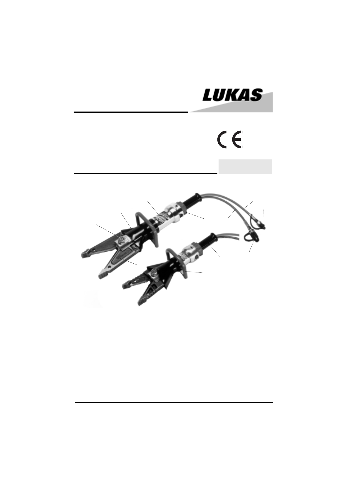
1 Control valve with star shape ring
2 Hydraulic cylinder
3 Protecting hose
4 Central bolt with selflocking nut
5 Cutter blades
6 Handle
7 Handle
8 Quick-connect socket
9 Hose, red: Pressure
10 Quick-connect plug
11 Hose, blue: Return
84150/6239-85 GB
Issue 09.2005
replaces 08.2003
11
10
1
6
9
7
8
1

1 Basic operation and designated use of the machine
1.1 The machine has been built in accordance with state-of-the-art standards and the recognized
safety rules. Nevertheless, its use may constitute a risk to life and limb of the user or of third parties,
or cause damage to the machine and to other material property.
1.2 The machine must only be used in technically perfect condition in accordance with its
designated use and the instructions set out in the operation manual, and only by safety-conscious
persons who are fully aware of the risks involved in operating the machine. Any functional disorders,
especially those affecting the safety of the machine/plant, should therefore be rectified immediately!
1.3 The machine is exclusively designed for the use described in the operating manual. Using
the machine for purposes other than those mentioned in the manual, such as driving and controlling
other pneumatic systems, is considered contrary to its designated use. The manufacturer/supplier
cannot be held liable for any damage resulting from such use. The risk of such misuse lies entirely
with the user.
Operating the machine within the limits of its designated use also involves observing the
instructions set out in the operating manual and complying with the inspection and maintenance
directives.
2 Organizational measures
2.1 The operating manual must always be at hand at the place of use of the machine!
2.2 In addition to the operating instructions, observe and instruct the user in all other generally
applicable legal and other mandatory regulations relevant to accident prevention and environmental
protection.
This also applies for wearing protective clothing, helmet with visor or goggles and protective gloves.
2.3 In order to avoid innjuries, the machine must only be operated by a specially trained operator
who has undergone a safety training.
2.4 Observe all safety instructions and warnings attached to the machine. Make sure that safety
instructions and warnings attached to the machine are always complete and perfectly legible.
2.5 Never make any modifications, additions or conversions without the supplier’s approval.
2.6 For repairs only genuine LUKAS spare parts, accessories or system components must be
used.
2.8 Adhere to prescribed intervals or those specified in the operating manual for routine checks
and inspections.
2.9 Make sure to dispose properly of packing material and dismounted parts!
3 General safety instructions
3.1 In the event of malfunctions, stop the machine immediately and lock it. Have any defects
rectified immediately.
3.2 Before starting up or setting the machine in motion and during operation of the machine make
sure that nobody is at risk.
2

3.3 Before transporting the machine always check that the accessories have been safely stowed
away.
3.4 Make sure that there is enough lighting during work.
3.5 Avoid any operation that might be a risk to machine stability.
3.6 Check the machine at least after every operation for obvious damage and defects. Report
any changes (incl. changes in the machine’s working behaviour) to the competent organization /
person immediately. If necessary, stop the machine immediately and lock it. All lines, hoses and
screwed connections have to be checked for leaks and obvious damage. Repair damage
immediately. Splashed oil may cause injury and fire.
3.7 All safety equipment has to be checked for completeness and flawless condition:
- instruction markings and warning signs (safety instructions)
- check safety cover (e.g. motor-safety covers, heat protection etc.) if they are available and
if they are in good condition.
3.8 Working under loads is not allowed if they are only lifted by hydraulic cylinders. If the work
is indispensable sufficient mechanical supports are needed additionally.
4 Instructions for maintenance and service
4.1 For the execution of maintenance and service work, tools and workshop equipment adapted
to the task on hand are absolutely indispensable.
Work on the hydraulic system must be carried out only by personnel having special knowledge and
experience with hydraulic equipment.
4.2 Before putting into operation clean the machine, especially connections and threaded
unions, of any traces of oil, fuel or preservatives before carrying out maintenance/repair. Never use
aggressive detergents. Use lint-free cleaning rags and pay attention that the components are
meticulously clean during reassembling after repair.
4.3 During dismantling of machines it is necessary to collect the outrunning hydraulic liquids
completely, so that they cannot reach the ground. They have to be disposed properly accord-ing
to the instructions.
4.4 Always tighten any screwed and thread connections that have been loosened during
maintenance and repair. Observe the stipulated torques.
4.7 Aggressive material (acid, lye, solvent, vapour) can damage the machine. It is necessary to
clean the whole machine if it must be exceptionally operated under such conditions or gets into
touch with these materials. Additionally, the machine must be checked as described under 3.6.
5 Safety Instructions for Hydraulic Hoses
A T T E N T I O N !
- by no means the hose must be exposed to brake fluid as this fluid will destroy outer
layer of hose
- do not expose the hose to any of the following aggressive fluids:
• acid, lye or solvent • alcohol and fuel • battery and automatic transmission fluid • phosphate
ester
Clean hose immediately with water and detergent when it was exposed to such fluids.
3
1
2
3
4
5
6
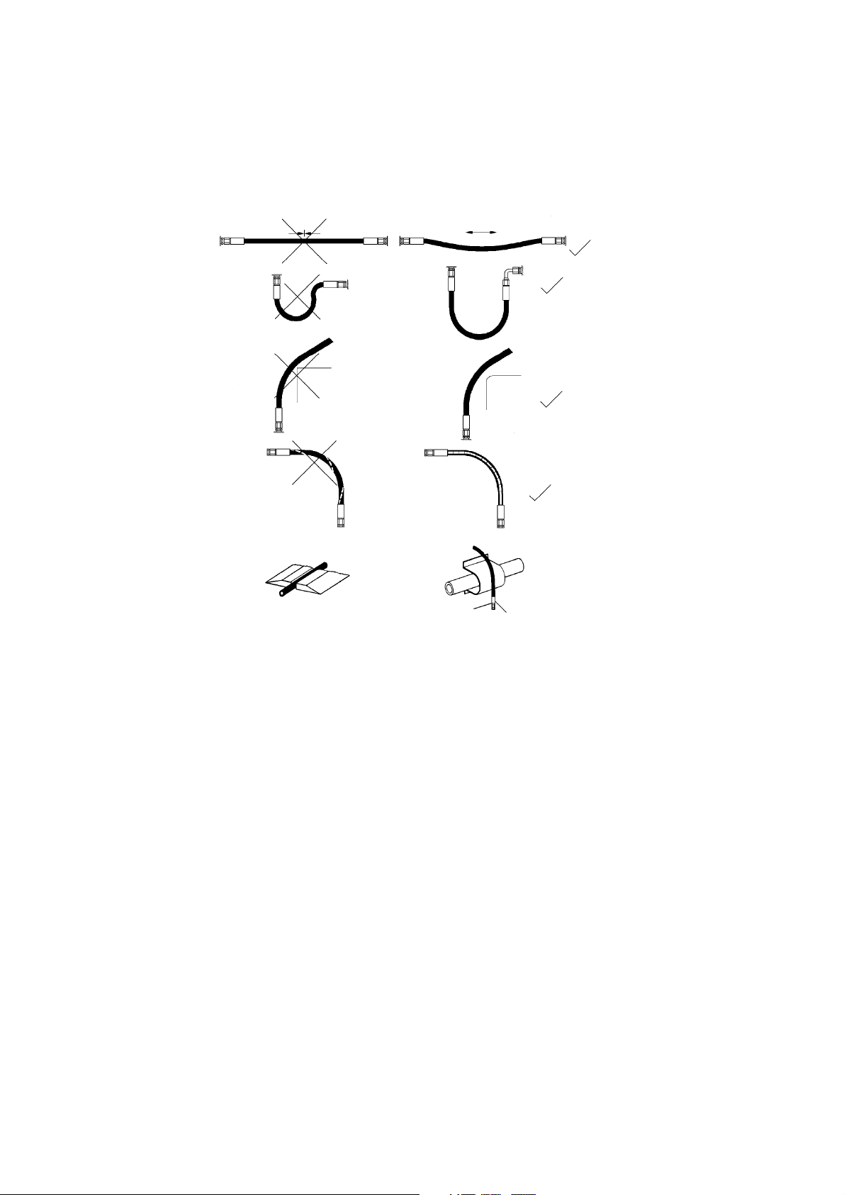
5.1 Handling of hoses
- never exceed the permissible working pressure as stated on hose and/or literature
- avoid any tension (see figure 1) and do not hang any load onto the hose
- never exceed the minimum bend radius as resulting kink will cause failure of hose (see figure
2)
- do not allow hose to contact sharp edges or rough objects (see figure 3)
- avoid any twisting of hose (see figure 4)
- do not run over hose with any vehicle or equipment ! Hoses which are put on the surface of
sidewalk or street have to be suitably protected (see figure 5)
- do not allow hose to contact areas of high temperature such as mufflers, exhaust manifold,
heaters or burners. Protect the hose as shown in figure 6 or install it in sufficient distance from
the source of heat.
- it is not allowed to attach weights to the hoses
- make sure that no objects fall on the hoses.
5.2 Protection of the working area in case of breakdown of hoses
Hoses have to be installed or protected in such a way that dangers are prevented, if possible, in
case of breakdown of the hoses.
Danger can be caused by:
- Uncontrolled hose movement after a hose rupture caused e.g. by external influence.
- Emerging of the pressure medium under pressure.
- Inflammation of pressure medium near igniting sources.
Dangers can be prevented by e.g. protective coverings or shieldings
4

5.2.1 Do not go near leaks!
- High pressure oil easily punctures skin causing serious injury,
gangrene or death!
- If injured, seek emergency medical help! Immediate surgery is
required to remove oil!
- Do not use finger or skin to check for leaks!
- Lower load or relieve hydraulic pressure befor loosening finttings!
5.3 Storage of hoses
- Hoses are subject to a natural aging even if they are stored correctly. Therefore, their storage
and service time is limited.
When storing the hoses please observe the following:
- Store them cool, dry and dustless (eventually wrapped with plastics sheeting); prevent direct
solar radiation and UV rays; shield heat sources which are near the hoses.
- Do not use any ozone producing lamps (e.g. fluorescent light sources, mercury-vapor lamp)
or electrical devices next to the hoses.
- Hoses have to be stored freely of tension and in a horizontal position. If they are stored in
rings the smallest bending radius determined by the manufacturer must not fall below.
5.4 Marking of hoses
- The hose is marked with the manufacturer's name and quarter/year of production.
- The max. allowable pressure and month/year of production is indicated on the hose end fitting.
5.5 Inspection and replacement intervals of hoses
- After each operation the hoses have to be checked for external damages, cracks, kinks
and bubbles!
- The operator has to replace the hoses in appropriate period of times, even if there are no
visible security defects on the hoses.
- The hoses have to be replaced 10 years as from date of manufacture at the latest (see
marking on the hose)!
Hoses are subject to a natural aging even if they are stored correctly. Therefore, their storage
and service time is limited.
- Hoses have to be checked by a skilled person before the first putting into operation of
the technical device and afterwards at least once a year for their safe working condition.
A skilled person is somebody having sufficient knowledge concerning hydraulic hoses due to his
special training and knowledge. He/she must be acquainted with the local safety working conditions,
accident prevention regulations, technical regulations and approved standards (e.g. DIN-Standards), so that he/she is capable to estimate the safety working conditions of the hydraulic hoses.
5

5.6 Examples for possible defects of hoses
- Damages of the surface and the interior (e.g. chafe marks, cuts or fissures).
- Embrittlement of the surface (fissuration of the hose material).
- Deformations, which are not in accordance with the natural shape of the hoses, in pressureless
condition or under pressure or in case of bendings, e.g. separation of material layers, blister
formation, squeezing or break spots.
- Leakage points.
- Instructions for installation were not observed.
- Emerging of the hose from the end fittings.
- Damages or deformations of the end fittings which deteriorate the function and stability of the
end fittings or the connection between hose and end fitting.
- Corrosion of the end fittings or the metal inlets, which deteriorates the function and stability.
- Storage and operation periods were exceeded.
6 Intended use
LUKAS combi tools LKS are specially designed for rescuing casualties in case of accidents within
road-, rail- or air traffic. Their main purpose is to free injured people after traffic accidents by cutting
open door hinges, door struts and roof struts. Furthermore people can be freed by spreading open
the car doors or pulling up the steering pillar using a chain set.
In general, objects can be pulled, spreaded or moved. In any case the objects to be manipulated
must be secured with massive prop-ups and supports.
The tools are suitable for submerged operation in water up to a depth of 40m.
7 Function and performance
7.1 Description
The devices are designed in such a way that a hydraulically actuated piston via mechanical joints
symmetrically closes two identical blade arms positioned opposite each other to cut the object in
question. The blade geometry is adapted to the application so as to avoid as far as possible a
sliding of the material to be cut. By opening the blade arms objects can be spread apart.
7.2 Connection diagram
For your better understanding the hydraulic diagram is
showing in simplified manner the tool's hydraulic
cylinder (A) with control valve (B).
7.3 Control of movements in operation
The arm movement is controlled by the firmly mounted star grip control valve (see cover page
item 1).
7.4 Hydraulic oil supply
LUKAS motor/engine pump or hand pump is used for operating the devices.
If the power pack comes from a manufacturer other than LUKAS, it must be ensured that it fulfils
the LUKAS specifications, as otherwise dangers may occur for which LUKAS cannot be held
liable. Especially it has to be made sure that the permissible working pressure of 63 MPa (630
bar) is not exceeded.
7.5 Hoses
The connection between motor pump and combi tools unit is normally effected with LUKAS hoses.
If pipes are to be used, please contact LUKAS.
6

8 Connection of the tool
8.1 Hydraulic
Two short hoses (each 0.5 m long) are fitted to the tool; they are connected with the motor pump
via a hose pair (5 m / 10 m / 20 m, as is necessary). All hoses are colour marked and have quickconnect couplings so that they can be connected without the risk of mix-up:
HP = High pressure ——> red R = reflux ——> blue
8.2 Connection of the plug-in coupling counterparts for HP and R hoses
The device is connected to the hydraulic pump with the plug-in coupling counterparts (plug and
socket), there being no risk of mix-up.
Before coupling, remove the dust protection covers and unlock the connect socket with adjusting
ring by turning it. Withdraw the sleeve and connect plug and socket while holding the sleeve in this
position. Release the sleeve and set the showglass to „red“ with the adjusting ring. Now the parts
are connected and locked. Decoupling is done in the reverse order.
Note regarding the modified release mechanism as of June 2004
When connecting the hoses, be aware of the following basic functions of the quick couplers:
X
Before coupling unlock the connect socket by turning the sleeve into position X. Retract sleeve
and connect plug and socket. Release sleeve and turn it into position Y.
Now the connection has been made and locked. Uncoupling is done in the reverse order.
Connection of the hoses is possible only, when they are depressurized.
In order to prevent contamination of the tool lines protect the couplings with delivered dust caps.
Attention!
Quick couplers partly have special functions. Therefore it is not allowed screwing them off from
the hoses or to exchange them.
Y
9 Operation
9.1 Preparatory measures
9.1.1 Initial start-up
Before initial start-up and after repairs, the device must be vented:
- Connect the device to the hydraulic pump (see item 8).
- Fully open and close the device at least twice without load (see item 9.2).
9.1.2 Inspection of operating state of the pump power pack
——> See separate Operating Instructions of the power pack (or manual pump) in question.
7

Note:
Before working on the motor pump or for coupling/decoupling the hoses, make sure that the motor
pump is switched off (electric connection) or disconnected from the mains and that the lines are
unpressurized.
9.2 Operating of the star grip 1
Opening of the arms:
Rotate star shape ring 1 to the right hand side and hold it in this position.
Closing of the arms:
Rotate star shape ring 1 to the left hand side and hold it in this position.
Load sustain function:
If released, the star shape ring 1 returns automatically to center position, maintaining fully the load
sustain function.
10 Cutting, Spreading and Pulling
10.1 Safety advise
Before the rescue operation begins, the object to be worked upon must be stabilized.
In each country, the country-specific safety regulations must be regarded.
When working in an environment which involves a risk of explosions, do not use motor/engine
powered pumps. Instead, use hand pumps.
When operating rescue devices, wear
- protective clothing
- helmet with visor or goggles
- protective gloves.
During operation of the spreader, parts of the object worked on may break away and endanger
people standing nearby. Onlookers must be kept at a safety clearance of at least 5m.
Do not get your hands in between the blade arms.
Do not cut
- live wires
- pressurized gas or fluid lines
- prestressed and hardened parts (such as springs, spring steels, steering columns, rolls)
- composite materials (steel/concrete)
10.2 Principles on cutting
The blades must be applied at a right angle to
the object to be cut. To enhance cutting
performance, cut as close as possible to the
blade fulcrum. On cutting, the gap between the
blade tips must not be larger than 3 mm
(LKS10: 2mm).
(Risk of blade fracture!)
10.3 Spreading
Use the tips only for widening the gap. When approximately half of the grooved area is used, the
full spreading power may be applied. Maximum force is exerted in the rear section of the tip.
8

Grip area too small. Tips may
break away.
Safe grip.
10.4 Pulling
10.4.1 Safety advise
- The chains may only be used for pulling with the rescue device.
- When pulling using a chain, make sure that bolt and hook are properly accommodated, so that
the chain does not slip off.
10.4.2 Fix the chain set provided for the individual tool properly as per chain set operating manual.
11 Dismantling of the device / Stop after operation
11.1 Combi tool
After operation, close the spreader arms to a tip distance of a few mm. This relaxes the unit
hydraulically and mechanically.
11.2 Hydraulic power pack
Stop the hydraulic power pack after operation.
This is mandatory before taking one of the following steps:
11.3 Hoses
Uncouple the red hose first and the blue hose second as described under 8.2. Put dust caps over
the couplings.
12 Maintenance
After operation or at the end of a shift inspect the components for perfect function (when the device
is dirty, clean it before inspection):
Visual inspection
Cutter arms
• Cutting edges free from spalling and deformation
• Distance of blades in transverse direction < 1mm
• Cutting surfaces slide past each other without contact
• Blades free from cracks
• Corrugation of the tips clean and edged without fissures
Combi tool
• No leakages
• Easy operation of the star grip
• Handle existing and fast
• Check of central bolt tightening torque (see also drawing to Section 13.3.1)
MA = Torque (see item 15.2)
9

Hoses
• check according safety instructions for hoses (see item 5)
• Check for oil leakage
Function testing
• Perfect opening and closing with the star grip valve.
13 Repairs
13.1 General
Servicing must be carried out only by the device manufacturer or by personnel trained by the
manufacturer or the authorised LUKAS dealers.
For replacement on all components, use only genuine LUKAS spare parts as specified in the spare
parts list, as here possibly required special tools, mounting information, safety aspects, testing
must absolutely be taken into account. See Section 4.
Protection of the device against hydraulic overload
Through uncorrect hose connection or temperature increase pressure can be built up in the cylinder
unintentionally. Therefore, the return hose (0,5m / blue) of the tool is equipped with a safety coupling
(quick connect plug, colour yellow). Overpressure (approx. 1.5 MPa) is released through this plug:
oil comes out. This oil is not a malfunction of the plug!
Should the tool have been equipped with couplers of different brand which do not have this safety
function, overpressure would be released through another safety valve (adjusted to approx.
30 MPa) included with the control valve block. In this case oil spill would be observed in the star
grip area.
As soon as sufficient pressure is released the valve becomes tight again. Should further constant
leakage ocur, please have the tool inspected by LUKAS personnel. On repair, protective clothing
is mandatory (see Section 1), as the cutter units can be pressurized also in unoperated state.
13.2 Preventive maintenance
13.2.1 Routine inspections
Regularly check the central bolt tightening torque. MA = Torque (see item 15.2)
Damaged blades can be repaired by regrinding of the cutting edge up to a total of 0.5 mm. Special
care must be taken to have the inner cutting faces run parallel.
13.2.2 General inspections
The mechanical transmission elements of the cutter unit are subjected to very high mechanical
stressing and must, therefore, be inspected at certain intervals. This helps to detect wear early so
that fractures of these wearing parts can be prevented by replacing them in time.
Parts in perfect condition can be fitted again after careful application of LUKAS special grease for
cutter units.
Parts with insignificant wear (fretting marks) can be repaired by polishing and fitted again after
greasing.
More pronounced wear marks require replacement of the damaged parts (by pairs).
At these intervals, crack testing of the cutter blades is equally mandatory. For this purpose, a special
crack test kit is available.
To protect the device against external corrosion clean its surface from time to time and slightly
grease it with oil.
13.2.3 Function and load test
If there is any doubt as to the safety and reliability of the equpiment, carry out an additional function
10

and load test. For this purpose, LUKAS offers a test kit as appropriate equipment.
13.2.4 Change of hydraulic oil
- after 200 uses, latest after 2 years, the hydraulic oil has to be changed.
- in any case if the oil of the pump (motor / hand pump) which belongs to the unit is changed.
By changing the used oil, it should be avoided that the new oil is polluted by the used oil of the
rescue tool.
Procedure:
The rescue tool is in closed (retracted) position • Change of oil has to be effected at the pump.
Screw off the return hose at the pump:
- in case of hose connection: screw off the connecting piece of the blue return hose.
- in case of quick connect couplings: screw off totally the coupling nut of the quick
connect coupling of the blue return hose.
Extend pump with tool slowly • Collect the used oil at the piston rod side in a separate tank and
dispose of the used oil (as the used oil of the pump) • Do not operate the pump any longer.
Connect the return hose again to the pump:
- Tighten the coupling nut of the quick connect coupling according to 13.3.6,
- Screw the hose nipple into the valve bloc with MA = 45 Nm,
- Ventilate the tool according to 9.1.1.
13.3 Repairs
13.3.1 Cutter blades / blade arms and levers
Cutter blades, blade arms and levers have to be replaced in the case of visual heavy damge and
cracks or when the blades are becoming too weak due to frequent regrinding. (13.2.1)
- Unscrew the nut of the central bolt (size open-jawed
spanner see 15.2) and drive out the central bolt.
- Remove the retaining rings with a pair of Seeger
ring pliers.
- Replace the blade arms after thorough cleaning and
greasing of the sliding surfaces.
- Tighten the nut of the central bolt with the tightening
torque specified in 15.2
- Note:
The bolts are accessible with the blade arms closed.
Attention: prior to mounting all sliding surfaces have to be carefully cleaned and greased with
LUKAS special grease.
Remark: Faulty parts such as blades, bolts or sliding disks have to be changed pairwise. The levers
have to be replaced if e.g. during change of blades damages appear such as wear on the surface,
cracks or deformation of the bores. Lever exchange should be made by a authorized LUKAS dealer
or the LUKAS service department.
13.3.2 Oil spill out of the control valve handle (see cover page item 7)
Pressure or return hose are not tightened properly.
Procedure:
Loosen the 2 allen screws (SW5) inside the handle sleeve and remove them together with the short
plastic isolation sleeves. Pull handle sleeve backwards until the hose connection points become
visible and retighten the retaining nut. Change hose connection sealing rings if necessary. Place
handle sleeve again and tighten it with the 2 allen screws. Make sure that the plastic isolation
sleeves are placed properly on the allen screws before mounting.
11

13.3.3 Change of protection boot
The rubber protection boot shall protect the operator against injuries caused by the moving levers.
If the boot is damaged it has to be replaced.
Procedure:
Remove the carrying handle (held by 2 screws) • Dismount cutter blades / blade arms (see 13.3.1)
• pull the faulty boot from the cylinder body and place the new one properly, i.e. that the carrying
handle fixing screws go easily through the corresponding holes in the boot. Mount and tighten
carrying handle.
13.3.4 Carrying handle (see cover page item 6)
Damaged carrying handles have to be replaced immediately.
Procedure:
Remove the handle (held by 2 screws) and change it against a new one • Change screws and disks
if necessary.
13.3.5 Labels
All damaged or illegible indentification stickers (Safety instructions, type label a.s.o) have to be
replaced.
Procedure:
Remove damaged stickers and clean surface with acetone • Put on new stickers.
13.3.6 Quick couplers
Quick couplers on the 0,5m hoses have to be replaced when
- external damage can be observed • the locking sleeve doesn´work any more • oil spill occurs
even when the coupling is properly connected
Remark: Faulty couplers have to be changed completely against genuine LUKAS spares, i.e. it is
not permissible to make any repair work.
The retaining nut on the hoses has to be tightened with a torque of MA = 45 Nm.
14 Troubleshooting
Trouble Check Cause Remedy
Hoses cannot be Pressurized Relieve pump pressure
coupled
On actuating blades Hoses correctly Air in the hydraulic Thoroughly vent pump
move slowly or by connected power system unit: see 9.1.1
jerks pack operating
No pressure build-up Not enough oil in hand Refill oil and vent the
Star grip doesn't return Return spring is Ask authorized dealer or
to middle position when damaged or return LUKAS themselves
released mechanism is dirty for repair
Oil leakage out of Untightness, eventually Replace hoses
hoses or hose fittings damages
Surface of hydraulic Contact with Change hoses
hoses is dissolved agressive fluids
Blades spread up at Torque of the center For retightening, see
tips to a gap of more bolt nut is unsuffisient 13.2.1
than 3 mm even if not
fully loaded
Leakages on the Seal defective piston Replacement of seals
piston rod rod by authorized dealer or
If the defects cannot be repaired, contact an authorised LUKAS dealer or the LUKAS service
department. The address: LUKAS Hydraulik GmbH, Weinstraße 39, D-91058 Erlangen, Pf 2560,
D-91013 Erlangen, service phone 09131/698 348; fax 09131/698 353
resp. motor pump. system (see operating
instruction 9.1.1)
LUKAS themselves
12

15 Technical data
Type LKS 35 EN LKS 20 EN LKS 10
Ref. No. 84150/6239 84150/6215 84150/1360
Dimensions l x w x h (mm)
without connection hoses
Blade opening min. (mm) 265 154 48
Spreading force (kN)
in all operating ranges
Spreading distance min. (mm) 360 235
Weight incl. oil filling (kg) 13.7 9.5 5.3
Operating pressure (MPa) 63*
Necessary oil quantity (l)
prEN 13204 MHCT 30 G UHCT 20 C
TÜV (DIN 14751) S 54-99TP 18
French standard NFS 61-571 CH150F / EH30 CH90D / EH 20
* 1MPa = 10 bar
1
Necessary oil quantity in the hydraulic power pack for operating the tool
(Difference in quantity piston / rode side)
15.1 Cutting performance / cutting forces
Type of Form of Strength
material material Rm (N/mm2)
Steel 450 50 x 50 x 5 35 x 35 x 4
Alu 400 28
The cutting performance is indicated for perfect condition of the blades (new or perfectly reground),
central bolts tightened in accordance with the specifications and correct handling (see section 9)
of the devices.
755 x 199 x 163 605 x 170 x 142 405 x 112 x 95
93 93
1
0.1 0.025 0.03
Dimensions of material
LKS 35 EN LKS 20 EN LKS10
550 Ø 28 Ø 20 Ø 16
750 Ø 25 Ø 15
450 100 x 10 60 x 5 20 x 10
400 65 x 40 x 6
400 80 x 40 x 6 50 x 25 x 2.6
400 60 x 3 42.6 x 2.6 22 x 3
15.2 Central bolt / Torque
Type LKS 35 EN LKS 20 EN LKS 10
Central bolt M 24 x 1.5 (SW 36) M 20 x 1.5 (SW 30)
Torque (Nm) 120 +10 100 + 10 80+ 10
13

15.3 Oil recommendations
For LUKAS hydraulic devices, use mineral oil in accordance with DIN 51 524 and others
Range of oil temperature Viscosity rating Remarks
A - 24 ... + 30 °C HL 5
B - 18 ... + 50 °C HLP 10
C - 8 ... + 75 °C HLP 22
D + 5 ... + 80 °C HLP 32
E - 8 ... + 70 °C HF - E 15 biodegradable
Recommended viscosity range: 10 ... 200 mm²/s,
delivered with HLP 22 to DIN 51 524
15.4 LUKAS Hoses
Bending radius Rmin = 38 mm
Burst resistance safety factor: burst pressure / max. operating pressure, min. 4 : 1
Temperature resistance - 40°C ... + 100°C
Operating medium Mineral oil according to DIN 51524
15.5 Others
Working temperature -20 ... +55°C
Ambient temperature (power pack in operation) -24 ... +45°C
Storage temperature (power pack not in operation) -30 ... +60°C
LUKAS Hydraulik GmbH
A Unit of IDEX Corporation
Weinstraße 39, 91058 Erlangen, Germany
Postfach 2560, 91013 Erlangen, Germany
Telefon +49(0)9131/698-0 • Telefax +49(0)9131/698-394
e-mail: info@lukas.de
LKS_84150_6239_Ag905_e.P6.5 Subject to revision
14
© Copyright 2000 LUKAS Hydraulik GmbH
 Loading...