

Page 1
Operating Instructions
Rescue Tools
Accu-tool
LKE 50 / LKE 51
LKE 55 / LKE 70
external accu 7 Ah
84150/7060-85 GB
Issue 02.2006
replaces 07.2005
1
Page 2

Contents page
1 Basic operation and designated use of the machine 4
2 Organizational measures 4
3 General safety instructions 4
4 Instructions for maintenance and service 5
5 Applications 6
6 Operation of LKE 50 / LKE 51 6
7 Operation of LKE 70 7
8 Operating the LKE 55 9
9 General remarks for working with LKE 10
10 Use of external accumulators 11
11 Loading the quick-change accu into the LKE 55 12
12 Exchanging blade arms 12
13 Preventive Maintenance 12
14 Troubleshooting 13
15 Technical Data 14
2
Page 3
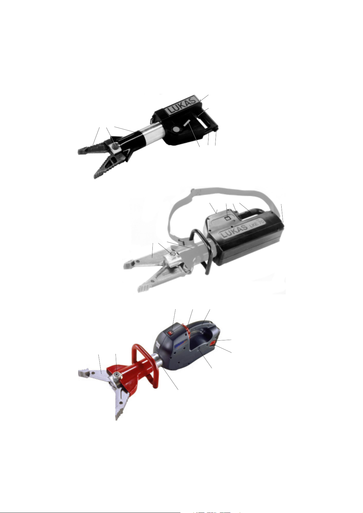
LKE 50 / LKE 51
6 7 8
3
2
1 4 5
1 Star grip
2 Main switch
3 LED indication panel
4 Handle
5 Socket 24 V
6 Blade arms
7 Central bolt with
self-locking nut
8 Cylinder body
7 8
6 7 8
LKE 55
2 1 5
9
3
3
LKE 70
6
2 1 4
3
4
1 Star grip
2 Main switch
3 Quick-change accu.
4 Release button for
quick-change accu.
5 Handle
6 Ventilation slits
7 Blade arms
8 Central bolt with
self-locking nut
9 Cylinder body
5
Page 4

1 Basic operation and designated use of the machine
1.1 The machine has been built in accordance with state-of-the-art standards and the recognized
safety rules. Nevertheless, its use may constitute a risk to life and limb of the user or of third parties,
or cause damage to the machine and to other material property.
1.2 The machine must only be used in technically perfect condition in accordance with its
designated use and the instructions set out in the operating manual, and only by safety-conscious
persons who are fully aware of the risks involved in operating the machine. Any functional disorders,
especially those affecting the safety of the machine/plant, should therefore be rectified immediately.
1.3 The machine is exclusively designed for the application mentioned in the operating instruc-
tions. Using the machine for purposes other than those mentioned above is considered contrary
to its designated use. The manufacturer/supplier cannot be held liable for any damage resulting
from such use. The risk of such misuse lies entirely with the user.
Operating the machine within the limits of its designated use also involves observing the
instructions set out in the operating manual and complying with the inspection and maintenance
directives.
2 Organizational measures
2.1 The operating instructions must always be to hand at the place of use of the machine.
2.2 In addition to the operating instructions, observe and instruct the user in all other generally
applicable legal and other mandatory regulations relevant to accident prevention and environmental
protection.
This also applies for wearing protective clothing, helmet with visor or goggles and protective gloves.
2.3 In order to avoid injuries, the machine must only be operated by a specially trained operator
who has undergone a safety training.
2.4 Observe all safety instructions and warnings attached to the machine.
Make sure that safety instructions and warnings attached to the machine are always complete and
perfectly legible.
2.5 Never make any modifications, additions or conversions which might affect safety without the
supplier’s approval. This also applies to the installation and adjustment of safety devices and
valves.
2.6 Spare parts must comply with the technical requirements specified by the manufacturer. This
is guaranteed from spare parts from original equipment manufacturers. It is only allowed to use
original LUKAS spare parts or LUKAS system components.
2.7 Adhere to prescribed intervals or those specified in the operating instructions for routine
checks and inspections.
2.8 Make sure to dispose properly of packing material and any removed parts!
3 General safety instructions
3.1 In the event of malfunctions, stop the machine immediately and lock it. Have any defects
rectified immediately.
4
Page 5

3.2 Make sure that nobody is at risk before starting up or setting the machine in motion and during
operation of the machine.
3.3 Before transporting the machine always check that the accessories have been safely stowed
away.
3.4 Make sure that there is enough lighting during work.
3.5 Avoid any operation that might be a risk to machine or to machine stability.
3.6 Check the machine at least after every operation for obvious damage and defects. Report any
changes (incl. changes in the machine’s working behaviour) to the competent organization/person
immediately. If necessary, stop the machine immediately and lock it. All lines, hoses and screwed
connections have to be checked for leaks and obvious damage. Repair damage immediately.
Splashed oil may cause injury and fire.
3.7 All safety equipment has to be checked for completeness and flawless condition:
- instruction markings and warning signs (safety instructions)
- check safety cover (e.g. motor-safety covers, heat protection etc.) if they are available and if
they are in good condition.
3.8 Working under loads is not allowed if they are only lifted by hydraulic cylinders. If the work
is cannot be avoided, it is essential that sufficient additional mechanical supports are used.
4 Instructions for maintenance and service
4.1 For the execution of maintenance and service work, tools and workshop equipment adapted
to the task on hand are essential.
Work on the hydraulic system must only be carried out by personnel who have special knowledge
and experience with hydraulic equipment.
4.2 Remove any trces of oil or dirt from the device before starting to use it, especially from the
connections and screws. Never use aggressive detergents. Use lint-free cleaning rags and pay
attention that the components are meticulously clean during reassembling after repair.
4.3 During dismantling of machines it is necessary to collect all of the exiting hydraulic liquids, so
that they cannot reach the ground. They have to be disposed properly according to the instructions.
4.4 Always tighten any screwed and thread connections that have been loosened during
maintenance and repair. Observe the stipulated torques.
4.5 Work on the electrical system or equipment may only be carried out by a skilled electrician
himself or by specially instructed personnel under the control and supervision of such electrician
and in accordance with the applicable electrical engineering rules.
4.6 The electrical equipment of machines is to be inspected and checked at regular intervals.
Defects such as loose connections or scorched cables must be rectified immediately.
4.7 Aggressive material (acid, brine, solvent, vapour) can damage the machine. It is necessary
to clean the whole machine if it must be exceptionally operated under such conditions or gets into
touch with these materials. Additionally, the machine must be checked as described under 3.6.
5
Page 6

Device-specific Information:
Do not reach in between the blade arms!
Do not cut electric wires!
Cutting objects under tension (shock absorbers, springs, steering links) is prohibited since the cutoff parts of these objects might jerk away unpredictably which exposes the operator and other
persons to a high risk of injury.
Hardened objects such as spring steel must not be cut.
Attention!
A „deep“ dischargement of the accumulator must be avoided, i. e do not further operate the tool
when the motor is running considerably slower than normal. In any case never try to further operate
the tool once the motor has stopped. This would reduce the lifetime of the accumulator.
5 Applications
The LKE has been exclusively designed for rescue purposes. As it is operated without any
additional power pack it is ideal for first intervention cars of rescue teams, police and civil defence.
Its purpose is to free injured people after traffic accidents by cutting door hinges, door struts and
roof struts, but they can also be used to open car doors.
In general, objects can be cut, spread or moved. In any case the objects to be manipulated must
be secured with massive prop-ups and / or supports.
The LKE has to be protected against humidity and moisture. During operation only blade arms can
be used under water.
External Accus (only LKE 50 / LKE 51 / LKE 70)
If more capacity than offered by the integrated accu is necessary, reserve accus can be
plugged to the tool with the charging cable (part of the charger set).
LKE 55
The LKE 55 operates with a quick-change accu that can be swapped at any time.
6 Operation of LKE 50 / LKE 51
6.1 Commissioning
Prior to commissioning the LKE 50 / LKE 51 has to be charged (see item 6.6).
6.2 Operation of LKE 50 / LKE 51
The tool is operated by the integrated or external accumulator, electrically driven motor and the
hydraulic pump.
The LKE is only activated by pushing the main switch (2) and the safety button (3) at the same time.
During operation the safety button is without function. Operation is stopped immediately by
releasing the main switch.
6.3 Open device (spreading)
Turn rotary knob down and start the tool.
6
Page 7

6.4 Close device (cutting)
Turn rotary knob upwards and start the tool.
The direction/operation process of the tool can be changed even when the tool is activated.
6.5 Safety switch off
If the max. working pressure is exceeded only the hydraulic pump is automatically switched to "idle"
(this can be deduced audibly), but the pressure in the system is maintained. In this case the tool
arms don’t move any more. Reposition the tool and start working again at a more suitable location.
6.6 Charging the LKE 50 / LKE 51
LKE 50 / LKE 51 is charged by connecting the LKE charger to the 24 V socket (5) on the tool. The
black cable (order no. 84150/7022) has to be used for this purpose. Once the charger is switched
on the charging procedure starts automatically (see also charger operation manual). During
charging the charge indication panel works even if the tool's main switch is in the "off“ position. This
enables the progress of charging to be checked visually.
The charging procedure may be interrupted at any time, if necessary. Just switch the charger off
and disconnect it from the tool.
Attention: Do not operate the LKE 50 / LKE 51 while it’s being charged !
When the charger is switched off or disconnected from its electric supply, the LKE 50 / LKE 51 (or
the external accumulator) must be disconnected from the charger. Otherwise the LKE 50 / LKE 51
(or the external accumulator) would be slowly discharged.
7 Operation of LKE 70
7.1 Commissioning
Prior to commissioning the LKE 70 has to be charged (see also item 7.9).
7.2 Operation LKE 70
The tool is operated by the integrated or external accumulator, electrically driven motor and
the hydraulic pump.
The LKE 70 is working only when the main switch (2) is switched on. With the main switch in position
"I" also the LED’s of the accu charge indication are lit. The LKE 70 is now ready for operation.
7.3 Opening of tool arms
The LKE 70 motor starts automatically when the star grip (1) is turned to either „opening“ or
„closing“. Turning the star grip to the right means causes the arms to open (= spreading).
7.4 Closing of tool arms
The tool arms are closed (= cutting) by turning the star grip (1) to the left.
7
Page 8

7.5 Load holding function / dead man’s function
As soon as the star grip is released it automatically returns to the neutral "zero" position which also
includes a load holding function. This means that the tool arms stay safely in their last position even
with the motor switched off.
7.6 Switching-off of the tool
After each operation the tool arms should be closed to a 5 to 10 mm’s gap. This relaxes the tool
both hydraulically and mechanically.
The main switch has to be set to "off" to prevent an unintended operation of LKE 70. If the main
switch stays "on" the accumulator would be slowly discharged by the LED indication panel (3).
7.7 Accumulator charge indication
LKE 70 is equipped with a charge indication panel (3) consisting of 5 LEDs which are lit
corresponding to the charge situation of the tool.
The panel includes 3 green LEDs
The tool accumulator is fully charged when all green LEDs and the yellow LED are lit.
Each LED represents 1/5 of the full accu capacity, i.e. when the red LED is on a charge of
20 % is still available.
Attention:
When the accumulator is deep discharged, a running light can be seen on the indication
panel. In this case the operation should be stopped immediately because the accumulator
could be damaged. The light is switched off again when the tool is charged.
1 yellow LED and
1 red LED.
7.8 Acoustic signal when the accumulator is empty
With model LKE 70 a signal is indicating that the accumulator becomes empty.
The signal sounds as soon as a rest capacity of 20 % is reached. It sounds 8 seconds and is
repeated every 24 seconds. Of course working can be continued until the accumulator is completely
empty.
The signal is interrupted when LKE 70 is switched off with the main switch (2), when an external
accumulator is connected or when LKE 70 is charged again.
7.9 Charging the LKE 70
LKE 70 is charged by connecting the LKE charger to the 24 V socket (5) on the tool. The grey cable
(order no. 84150/7023) has to be used for this purpose. Once the charger is switched on the
charging procedure starts automatically (see also charger operation manual).
During charging the charge indication panel works even if the tool's main switch is in the "off“
position. This enables the progress of charging to be checked visually.
The charging procedure may be interrupted at any time, if necessary. Just switch the charger off
and disconnect it from the tool.
Attention: Do not operate LKE 70 while it’s being charged !
8
Page 9

When the charger is switched off or disconnected from its electric supply, the LKE 70 (or the
external accumulator) must be disconnected from the charger. Otherwise the LKE 70 (or the
external accumulator) would be slowly discharged.
This discharging process will not be shown on the charge indication panel, i. e. it would shown "full"
even when the device is partly discharged. The charge indication panel will work correctly again
once the tool has been fully discharged (see item 7.10).
7.10 Calibration of the charge indication panel
If the LKE 70 is frequently partially discharged, but then fully charged again, the preciseness of the
indication panel could suffer. To prevent this, the accumulator should be fully discharged at least
after 5 operations. A full discharging automatically calibrates the indication panel again.
7.11 Motor temperature control
The LKE 70 is equipped with a motor temperature control. If the permissible motor temperature is
exceeded, the LEDs of the capacity control panel blink. If this happens, the tool should be switched
off immediately.
Only in an extreme case should the rescue work be continued, however with the risk of a motor
damage.
7.12 Safety switch-off
If the max. working pressure is exceeded only the hydraulic pump is automatically switched to „idle“,
but the pressure in the system is maintained. In this case the tool arms don’t move any more.
Reposition the tool and start working again at a more preferable position.
8 Operating the LKE 55
8.1 First commissioning
The quick-change accu must be charged before the device is used for the first time.
8.2 Changing the accus
In order to change the accus, press both release buttons (4) down completely, and pull the accu
out backwards.
When inserting the accus, ensure that they audibly click into place.
Pay particular attention that no foreign material can enter the battery compartment when the accu
is removed, since this will damage the contacts when the accu is reinserted.
8.3 Starting the LKE 55
The device is driven by the accu, an electric motor and a hydraulic pump.
In order to be able to use the device, the main switch (2) must first be in position "I". The device
is now ready to be operated, but the motor is off.
9
Page 10

8.4 Opening of tool arms
The LKE 55 motor starts automatically when the star grip (1) is turned to either "opening" or
"closing". Turning the star grip to the right means causes the arms to open (= spreading).
8.5 Closing of tool arms
The tool arms are closed (= cutting) by turning the star grip (1) to the left.
8.6 Load holding function / dead man's function
As soon as the star grip is released it automatically returns to the neutral „zero“ position which
includes also a load holding function. This means that the tool arms stay safely in their last position
even with the motor switched off.
8.7 Switching-off of the tool
After each operation the tool arms should be closed to a 5 to 10 mm’s gap. This relaxes the tool
both hydraulically and mechanically.
The main switch has to be set to „off“ to prevent an unintended operation of LKE 55.
8.8 Motor temperature
The housing of the LKE 55 contains ventilation slits to prevent the motor overheating. These must
never be covered when the motor is in operation.
Furthermore, ensure that no dirt or moisture can enter. The device is not damaged if it is used in
the rain, so long as it is stored in a dry location.
8.9 Safety switch off
If the max. working pressure is exceeded only the hydraulic pump is automatically switched to "idle"
(this can be deduced audibly), but the pressure in the system is maintained. In this case the tool
arms don’t move any more. Reposition the tool and start working again at a more suitable location.
9 General remarks for working with LKE
9.1 Cutting
The blade arms must be applied in a right angle to the object to be cut. To enhance cutting
performance, cut as close as possible to the round stock cutting edge.
10
Page 11

9.2 Spreading
Use the frontmost area of the tips only for enlarging the gap. The maximum spreading force can
be applied if approx. 50% of the grooved section of the bladearm tips is used.
9.3 After Operation
The blade arms should be closed up to 5 to 10 mm. This relaxes the device hydraulically and
mechanically.
10 Use of external accumulators
(only for LKE 50, LKE 51 and LKE 70)
10.1 General
Both LKE 50 / LKE 51 and LKE 70 can be connected to external accumulators. Following
external accus are available:
- 1.7 Ah - external accu in a robust leather cover, ref. no. 84150/7021.
- 7 Ah - external accu in stable plastic housing, ref. no. 84150/7028.
Both accu types are suitable for LKE 50 / LKE 51 and LKE 70.
10.2 Charge indication with external accu 7 Ah
The 7Ah external accu is equipped with a charge indication panel similar to the one on LKE
70 (see also item 7.7). The panel is activated as soon as current is flowing, i.e. during
charging as well as during discharging.
The panel automatically switches off after charging / discharging. It does so after a delay of approx.
30 minutes to allow it to be read during short breaks in the work.
10.3 Charging the external accumulator
The external accumulator 1.7 Ah (in leather bag) is connected to the charger with the black
charging cable (ref. no. 84150/7022). Charging is then carried out automatically.
The external accumulator 7 Ah is connected to the charger with the built-on cable (see operating
instructions for the charger).
The external accumulator discharges slowly when the charger is switched off or disconnected from
its electricity supply. This discharging process will not be shown on the charge indication panel, i.e.
it shows "full" even if the accumulator is partly discharged. The charge indication panel works
correctly again once the accumulator has been fully discharged (see item 7.10).
10.4 Acoustic signal when the accumulator is empty
Like with the LKE 70, also the 7 Ah accumulator includes a signal indicating that it is becoming
empty (see also item. 7.8).
11
Page 12
10.5 Calibration of charger indication panel
If the external accumulator 7 Ah is frequently partially discharged, but then fully charged again, the
preciseness of the indication panel could suffer. To prevent this, the accumulator should be fully
discharged at least after 5 operations. A full discharging is automatically calibrating the indication
panel again.
10.6 Safety advice for spare accus:
- Don’t throw them into fire.
- Protect them against humidity.
- Avoid short circuit (e.g. through metal parts) on the electric plug.
- Dispose of used accus properly.
11 Loading the quick-change accu into the LKE 55
The accu is charged automatically by placing it in the charging compartment of the charging device.
It is important that you read the operating manual of the charging device before charging.
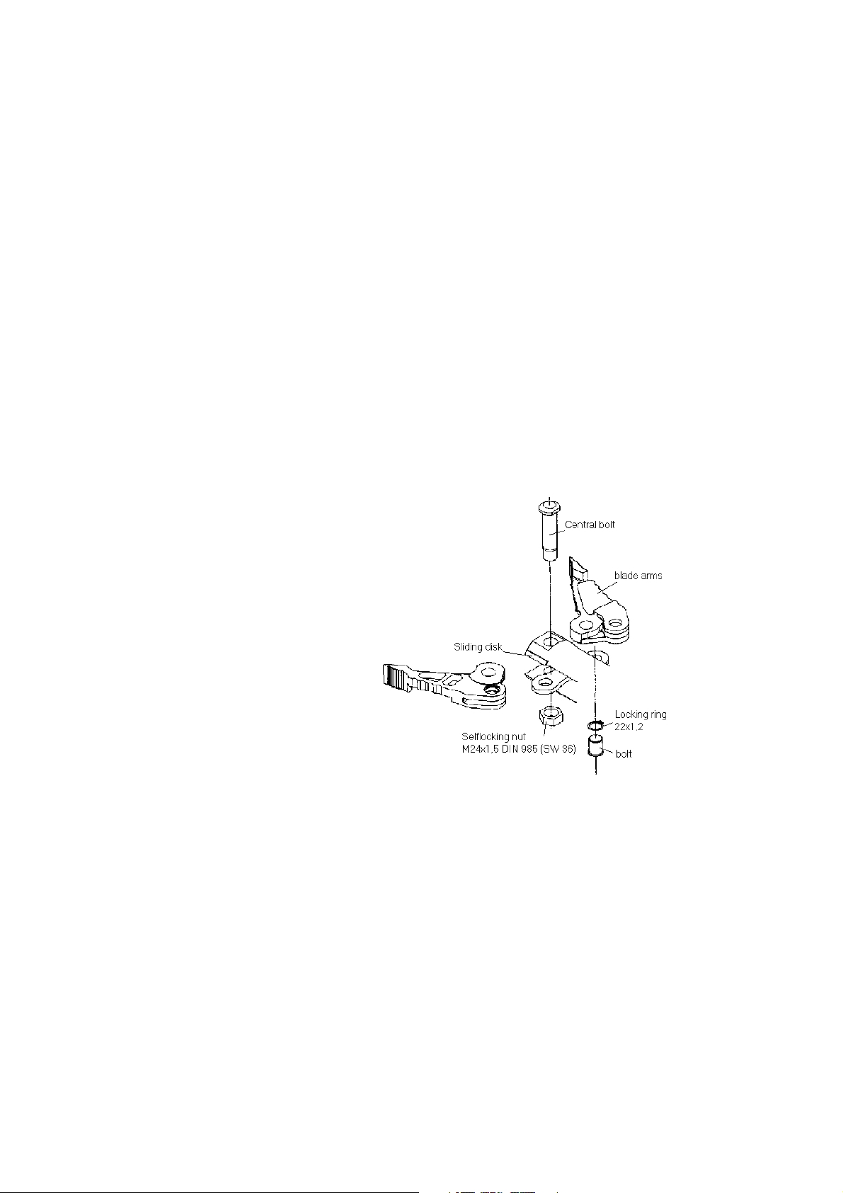
12 Exchanging blade arms
- Unscrew the nut of the central bolt and drive out
the central bolt (double fixed spanner 32 x 36).
- Remove the retaining ring with a pair of Seeger ring pliers.
- Replace the blade arms after thoroughly applying
grease to the sliding surfaces.
- Tighten nut of LKE 50 / LKE 51 central bolt with100 Nm,
of LKE 55 with 110 Nm
and 120 Nm with LKE 70.
13 Preventive Maintenance
In order to ensure permanent proper function and safety for the rescue device, a visual inspection
has to be made after each use or at least once a year. Pay special attention to those parts which
carry loads, such as hinges or bolts. Also the rotary lever (1) (LKE 50 / LKE 51) resp. the star grip
(1) (LKE 55 / LKE 70) has to be checked for easy movement.
Every 3 years or if there is any doubt as to the safety or reliability of the equipment, carry out an
additional function and load test. The operational and load test should be carried in accordance with
the regulations of GUV.
Control of oil level and change of internal accu
The oil level has to be checked by trained personnel if the blade arms cannot be closed
completely.
It is recommended by LUKAS to have the oil changed by trained personnel after 5 years,
depending on the frequency of use.
12
Page 13

If the capacity of the installed accu constantly decreases despite proper charging, it must be
replaced by a qualified person.
Maintenance advice
Apply oil to the metal surfaces of the device from time to time except the electrical contacts.
13.1 Oil for LUKAS hydraulic devices
Mineral oil in accordance with DIN 51524
HLP 10, recommended range of viscosity: 10..200 (mm2/s).
14 Troubleshooting
Trouble Remedy Carried out by
Blade arms cannot be closed completely Refill oil
LKE 50 / 51 / 70
The LKE's effective operating time insert new accu
between the individual charging cycles LKE 55
decreases steadily despite proper charging use new changeable User
accu
The material to be cut slides between the blade Tighten User
arms during the cutting procedure central bolt (7) (see item 15.2)
Device does not reach pressure
Motor cannot be started
Additional documentation:
LKE 50 : Spare parts list 84150/7010; service manual 84150/7010-84.
LKE 51: Spare parts list 84150/7040; service manual 84150/7010-84.
LKE 55: Spare parts list 84150/7060.
LKE 70: Spare parts list 84150/7025.
Trouble shooting by service garage
Authorized
service garage
If the defects cannot be repaired, contact an authorized LUKAS dealer or the LUKAS service
department. The address: LUKAS Hydraulik GmbH, Weinstraße 39, 91058 Erlangen, Germany;
P.O. Box 2560, 91013 Erlangen Germany; Service-phone.: +49 / 91 31 / 6 98 - 3 38;
Fax: +49 / 91 31 / 69 83 53.
13
Page 14

15 Technical data
Type LKE 50 LKE 51 LKE 70 LKE 55
Order no. 84150/7010 84150/7040 84150/7034 84150/7060
Dimensions l x w x h (mm) 720x230x134 742x233x134 860x270x173 807x200x267
Operating pressure (MPa) 67 58 63
Weight* (kg) 15.8 15.2 22.8 15.6
Weight without handle and carrier belt (kg) 15.2 14.6 -- --
Opening time without load (sec) 6 8 7 8
Closing time without load (sec) 6.5 8.5 9 9
Max. distance between tips (mm) 200 256 300 316
Spreading force 25 mm from tips (kN) 26 ... 30 32 ... 37 28 ... 35
Pulling force with chain set KSV 7 (kN) 25 ... 27 24 ... 27 -- --
Pulling distance with chain set KSV 7 (mm) 220 285 -- --
Pulling force with chain set KSV 8 (kN) -- 33 ... 39 26 ... 33
Pulling distance with chain set KSV 8 (mm) -- 305 320
Cutting class according to EN 13204 D D G E
*Weight (including oil filling, handle and carrier belt):
Oil specifications: delivered with mineral oil HLP 10 DIN 51524 (closed oil cycle).
Specifications according to NFPA 1936:
Type LKE55
Cutting class A5 B5 C5 D7 E7
LSF (kN / lbs) 23.4 / 5,250
HSF (kN / lbs) 26.3 / 5,910
LPF (kN / lbs) 30.7 / 6,910
HPF (kN / lbs) 35.2 / 7,910
15.1 Maximum cutting performance of LKE
The following materials (according to EN 13204, S235JR) can be cut :
Max. Dimensions of Material
Type of Form of LKE 50 LKE 51 LKE 70 LKE 55
material material mm mm mm mm
21 27 26
60 x 5 100 x 10 80 x 8
Steel 40 x 40 x 4 55 x 55 x 4 55 x 55 x 4
42.4 x 2.6 76.1 x 3.2 60.3 x 2.9
50 x 25 x 2.5 80 x 40 x 3 60 x 40 x 3
With hollow profiles outside dimensions x wall thickness.
Remark:
The cutting performance is indicated for perfect condition of the blades (new or perfectly reground),
central bolts tightened in accordance with the specifications and correct handling (see item 9) of
the devices.
14
Page 15

15.2 Central bolt / Tightening torque
Type LKE 50 / LKE 51 LKE 70 LKE 55
Central bolt M 24 x 1.5 (SW 36)
Torque Nm 100+10 120+10 110+10
15.3 Noise emission
Type LKE 50 LKE 51 LKE 70 LKE 55
Following the regulations No load 65 dB 63 dB 68 dB Measuring
of EN ISO 3744 Full load 69 dB 67 dB 70 dB distance 1.0 m
15.4 Others
LKE 50 / 51 / 70 LKE 55
Temperature ranges °C °C
Ambient temperature (when charging the accu) + 5 ... + 40 0 ... +45
In exceptional cases (with decreased accu life time) + 5 ... + 50 --
Ambient temperature (during rescue operation) - 20 ... + 60
Storage temperature (device not in operation) - 30 ... + 60
LUKAS Hydraulik GmbH
A Unit of IDEX Corporation
Weinstraße 39, 91058 Erlangen
Postfach 2560, 91013 Erlangen • Germany
Tel.: + 49 (0) 9131 / 698-0
Fax + 49 (0) 9131 / 69 83 94
Internet: http://www.lukas.de
e-mail: info@lukas.de
LKE_84150_7060_Ag0206_e.P65 subject to revision
15
© Copyright 2003 LUKAS Hydraulik GmbH
 Loading...