

Page 1
Operating Instruction
LAA
Pulling Device
3
84072/4065- 85 GB
Edition 07.2010
replaces 7.2000
2
1
3
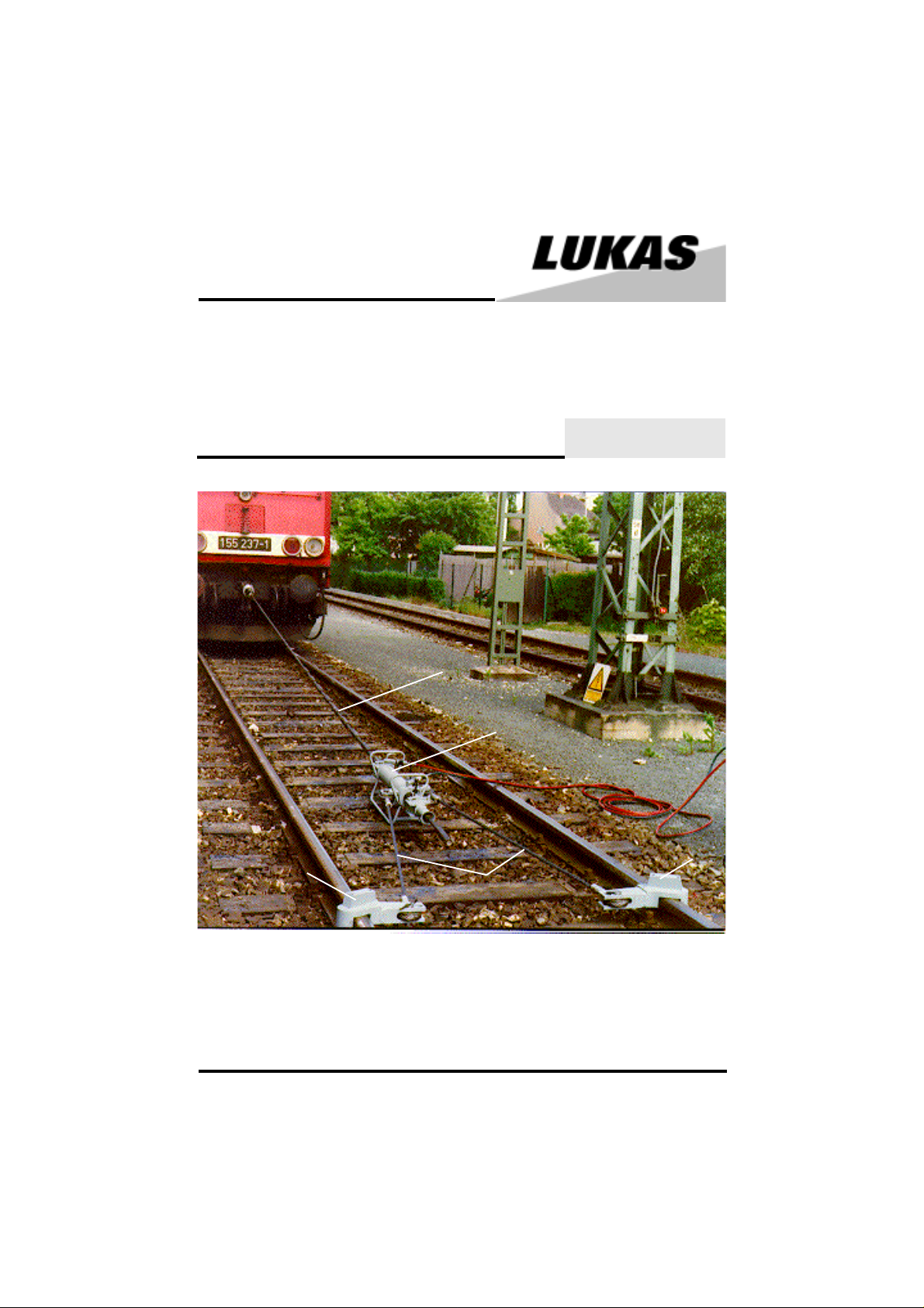
4
1 Hydraulic cylinder HOP
2 Pulling rope
3 Rail attachment
4 Holding rope
1
Page 2

Safety instructions
1000 Basic operation and designated use of the machine
1100The machine has been built in accordance with state-of-the-art standards and the recognized
safety rules. Nevertheless, its use may constitute a risk to life and limb of the user or of third parties,
or cause damage to the machine and to other material property.
1200The machine must only be used in technically perfect condition in accordance with its
designated use and the instructions set out in the operating manual, and only by safety-conscious
persons who are fully aware of the risks involved in operating the machine. Any functional disorders,
especially those affecting the safety of the machine/plant, should therefore be rectified immediately.
1300The machine is exclusively designed for longitudinal movement of loads. Using the
machine for purposes other than those mentioned above is considered contrary to its designated
use. The manufacturer/supplier cannot be held liable for any damage resulting from such use. The
risk of such misuse lies entirely with the user.
Operating the machine within the limits of its designated use also involves observing the instructions
set out in the operating manual and complying with the inspection and maintenance directives.
1400An operating error could cause the destruction of the pulling device
2000 Organizational measures
2100The operating instructions must always be at hand at the place of use of the machine,
e. g. by stowing them in the tool compartment or tool-box provided for such purpose.
2200In addition to the operating instructions, observe and instruct the user in all other generally
applicable legal and other mandatory regulations relevant to accident prevention and environmental
protection.
This also applies for wearing protective clothing, helmet with visor or goggles and protective gloves.
2300In order to avoid injuries, the machine must only be operated by a specially trained operator
who has undergone a safety training.
2400Observe all safety instructions and warnings attached to the machine.
Make sure that safety instructions and warnings attached to the machine are always complete and
perfectly legible.
2500Never make any modifications, additions or conversions which might affect safety without
the supplier’s approval. This also applies to the installation and adjustment of safety devices and
valves.
2600Spare parts must comply with the technical requirements specified by the manufacturer.
Spare parts from original equipment manufacturers can be relied to do so. It is only allowed
to use original LUKAS spare parts or LUKAS system components.
2700Replace hydraulic hoses within stipulated and appropriate intervals even if no safety-relevant
defects have been detected. This has to be done after 10 years at the latest.
2800Adhere to prescribed intervals or those specified in the operating instructions for routine
checks and inspections.
3000 General safety instructions
3100In the event of malfunctions, stop the machine immediately and lock it. Have any defects
rectified immediately.
2
Page 3

3200Before starting up or setting the machine in motion and during operation of the machine make
sure that nobody is at risk.
3300Before setting the machine in motion always check that the accessories have been safely
stowed away.
3400Make sure that there is enough lighting during work.
3500Avoid any operation that might be a risk to machine stability.
3600Check the machine at least after every operation for obvious damage and defects. Report any
changes (incl. changes in the machine’s working behaviour) to the competent organization/person
immediately. If necessary, stop the machine immediately and lock it. All lines, hoses and screwed
connections have to be checked for leaks and obvious damage. Repair damage immediately.
Splashed oil may cause injury and fire.
3700All safety equipments have to be checked for completeness and flawless condition:
- instruction markings and warning signs (safety instructions)
- check safety cover (e.g. motor-safety covers, heat protection etc.) if they are available and
if they are in a good condition
3800Working under loads is not allowed if they are only lifted by hydraulic cylinders. If the work
is indispensable sufficient mechanical supports are needed additionally.
3900Make sure that hoses are not mechanically stressed (pulling, bending etc.)
4000 Instructions for maintenance and service
4100For the execution of maintenance and service work, tools and workshop equipment adapted
to the task on hand are absolutely indispensable.
Work on the hydraulic system must be carried out only by personnel having special knowledge and
experience with hydraulic equipment.
4200Before putting into operation clean the machine, especially connections and threaded unions,
of any traces of oil, fuel or preservatives before carrying out maintenance/repair. Never use
aggressive detergents. Use lint-free cleaning rags and pay attention that the components are
meticulously clean during reassembling after repair.
4300During dismantling of machines it is necessary to collect the outrunning hydraulic liquids
completely, so that they cannot reach the ground. They have to be disposed properly according to
the instructions.
4400Always tighten any screwed and thread connections that have been loosened during
maintenance and repair. Observe the stipulated torques.
4500Work on the electrical system or equipment may only be carried out by a skilled electrician
himself or by specially instructed personnel under the control and supervision of such electrician
and in accordance with the applicable electrical engineering rules.
4600The electrical equipment of machines is to be inspected and checked at regular intervals.
Defects such as loose connections or scorched cables must be rectified immediately.
4700Aggressive material (acid, lye, solvent, vapour) can damage the machine. It is necessary
to clean the whole machine if it must be exceptionally operated under such conditions or gets
into touch with these materials. Additionally, the machine must be checked as described under 3060.
5000 Safety instructions for hydraulic hoses
All instructions as to safe use of hydraulic hoses can be found in the booklet HR 1495 35 219
delivered with the hoses.
3
Page 4

6000 Intended use
The LUKAS Pulling Device serves for pulling rolling stock in or opposite to their driving direction.
Furthermore run-up rail vehicles can be pulled apart after an accident.
For operation of the device only genuine LUKAS motor pumps and control tables must be used.
7000 Description
The pulling device consists of the following components (see cover page):
7100Hydraulic cylinder "HOP" (1) with through bore to accomodate the pulling rope. The cylinder
is double-acting, i. e. the piston advances and returns hydraulically.
7200Pulling rope (2) with pressed-on sleeves and pulling eye on one end.
7300Two rail attachments (3) which are wedged on top of the rails. They serve as counter
support for the pulling movement.
7400Two holding ropes (4) - with fixing eyes on both ends - for connection between the pulling
cylinder and the rail attachments.
8000 Installation
8100Fasten the end of the pulling rope c/w pulling eye to the object to be pulled, e. g. with a suitable
shackle or further steel wire ropes. Fasten the rope as low as possible above the ground.
Attention:
Make sure that all accessories provided by yourself have a sufficient safety factor as
against the max. pulling force of 22 tons!
8200Set the pulling cylinder up between the rails in a distance of approx. 8 m as from the object
to be pulled. Observe that the "trumpet"-shaped end of the cylinder has to point away from the
vehicle.
8300Unlatch the pulling rope arresting mechanism (on front and rear end of the cylinder) as
follows:
Lift the spring-loaded pin.
fig. 1
4
Page 5

Move the arresting lever backwards until it latches in the end position.
trumpet
fig. 2
8400Insert the pulling rope into the pulling cylinder and push it through until the first sleeve
becomes visible at the trumpet-shaped tube.
8500 Latch the arresting mechanism again (reverse the sequence as described und item 8300).
Make sure that both arresting lever and spring-loaded pin properly lock in their end positions.
8600 Connect the two holding ropes with the attachment on the pullling cylinder as follows (see
fig. 3):
3c
3a
fig. 3
Remove the securing pin (3a) on one end of the fixing bolt and take the bolt out. Insert the fixing
eye (3b) of the pulling rope into the attachment and arrest the eye by means of the fixing bolt (3c).
Fix the fixing bolt with the securing pin again so that it cannot slide out.
5
3b
Page 6

8700 Put the rail attachment on top of the rails as shown in figure 4.
Observe that the rail attachments ar not identical, i. e. there is a "left" and a "right" one.
8800 Connect the other ends of the holding ropes with the rail attachement as desribed under
item 8600.
holding
pulling
rope
arresting
mechanism
rope
rail attachement
Pulling device mounted ready for operation
fig. 4
9000 Hydraulic connection
9100 Connect a red/blue hose pair to motor pump / control table. For proper connection, adhere
to the separate operating manual of the power and control unit. The hydraulic function of the pulling
cylinder is the same as with LUKAS lifting cylinders, i. e. you must connect it to a control valve
that you normally use for lifting.
9200 Couple the blue hose with the return connection (R) on the pulling cylinder (see fig. 4).
9300 Couple the red hose with the high pressure connection (P) on the pulling cylinder (see
fig. 4).
10000 Operation
10100 Safety advise
Place the power and control unit in an as great as possible distance from the pulling
device and make sure that no personell is in a radius of at least 10 m around the pulling
device. Even when the device is properly used, parts of the object to be pulled might
split apart. Injury might be caused by such parts, respectively by the pulling rope itself
should it whip in an uncontrolled movement!
10200 Switch the motor pump on (see separate manual).
10300Switch the valve on the control unit to "lifting" (see separate manual). Now the pulling
cylinder extends with movement of the pulling rope and the object will be pulled.
6
Page 7

10400 When the pulling cylinder is fully extended, you can continue with pulling without any manual
resetting: switch the control valve to "lowering", and the pulling cylinder will be retracted without
a movement of the pulling rope. As the pulling rope latches automatically, the pulling procedure
can be started again as soon as the pulling cylinder is in fully retracted position.
The "pull and retract" procedure can be repeated as long as sufficient pulling rope is available.
11000 Dismantling of the device
11100 Make sur that pulling rope and holding ropes are no longer under tension. If necessary,
release tension from the ropes by advancing and retracting the pulling cylinder.
11200 Set the control valve on the control table to middle position and switch the motor pump
off.
11300 Uncouple the red hose first, and then the blue hose.
11400 Remove the fixing bolts for the holding ropes on pulling cylinder and rail attachments and
remove the holding ropes.
11500 Unlatch the pulling rope arresting mechanism as described under 8300 and pull the rope
completely out of the pulling cylinder.
7
Page 8

11000 Technical data
Pulling cylinder HOP 22/460 R
Operating pressure 50 MPa
Stroke 460 mm
Pulling force 220 kN
Oil capacity 1 l
Pulling rope
Length 9,5 m
Max. permissible load 220 kN
Holding rope
Length 3 m
Max. permissible load 220 kN
Zuggerät
Order no. 84072/4065
Max. permissible load 220 kN
Total weight 194 kg
Required connection hose pair
10 m red/blue
Order no. 84072/1765
LUKAS Hydraulik GmbH
A Unit of IDEX Corporation
Weinstraße 39, 91058 Erlangen • Germany
Postfach 2560, D-91013 Erlangen • Germany
Telefon +49 (0) 9131/698-0 • Telefax +49 (0)9131/698-394
e-mail: lukas.info@idexcorp.com
Pulling_device_BA_GB_84072406585_0710.p65
8
© Copyright 2010 LUKAS Hydraulik GmbH
 Loading...