

Page 1
Operating Instructions - Hydraulic tools
Hydraulic cylinder
(Translation of the original operating instructions)
83145000085 GB
Edition 08.2011
replaces 09.2008
Page 2

2
Page 3

Contents Page
1. Hazard classes 4
2. Product safety 5
3. Intended use 8
4. Equipment designation 9
5. Functions and performance 9
5.1 Description 9
5.2 Basic construction of the cylinder 10
5.3 Controlling the operating movements 11
5.4 Hydraulic supply 12
6. Connecting the equipment 13
6.1 Hydraulic connections 13
6.2 Coupling the screwed couplings 13
6.3 Coupling Quick-disconnect Couplings 14
7. Operation 15
7.1 Basic selection of cylinder size 15
7.2 Positioning 15
7.3 Commissioning 18
7.4 Hydraulic control of the cylinder 19
8. Dismantling the equipment / deactivation following operation 20
8.1 Hydraulic cylinder 20
8.2 Hydraulic unit 20
8.3 Hoses 20
9. Care and Maintenance 21
10. Repairs 22
10.1 General information 22
10.2 Preventive maintenance 22
10.3 Repairs 23
11. Troubleshooting 26
12. Technical data 29
12.1 Cylinder data 29
12.2 Hydraulicuidrecommendations 29
13. Notes 30
3
Page 4
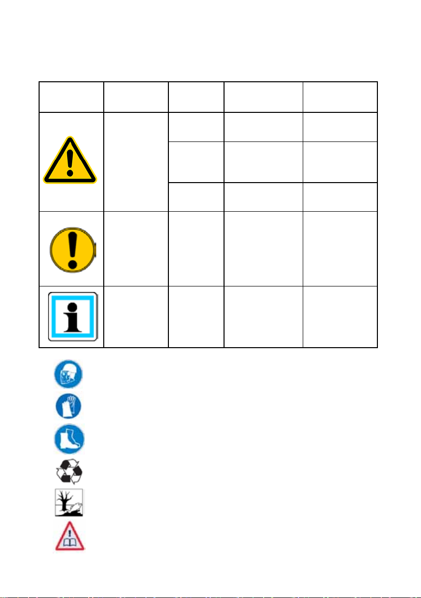
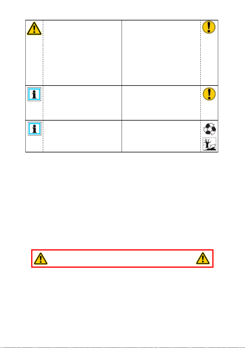
1. Hazard classes
We distinguish between various categories of safety instructions. The chart below provides
an overview, using symbols (pictograms) and signal words, of the specic danger and the
possible consequences.
Pictogram
Wear helmet with face protection
Damage /
injury to
human
device
- NOTE
Key word Denition Consequences
DANGER! Immediate danger
WARNING!
CAUTION!
CAUTION!
Potentially
dangerous
situation
Less dangerous
situation
Danger of damage
to device /
environment
Advice for
application and
other important /
useful information
and advice
Death or major
injury
Potential death or
major injury
Minor or slight
injury
Damage to the
equipment,
damage to the
environment,
damage to
surrounding
materials
No injury /
damage to
persons /
environment /
equipment
Wear protective gloves
Wear safety shoes
Proper recycling
Observe the principles of environmental protection
Read and observe the operating instructions
4
Page 5
2. Product safety
LUKAS products are developed and manufactured to ensure the best performance and
quality with intended use.
The safety of the operator is the most important consideration in the product design.
Furthermore, the operating instructions are intended to help in using LUKAS products safely.
In addition to the operating instructions, all generally applicable, statutory and other
binding rules for accident prevention and for environmental protection must be heeded and
disseminated.
The device may only be operated by appropriately educated, safety trained persons, since
otherwise there is a risk of injury.
We would like to point out to all users that they should read the operating instructions carefully
before using the equipment and comply with the instructions there without reservation.
We further recommend that a qualied instructor train you in the use of the product.
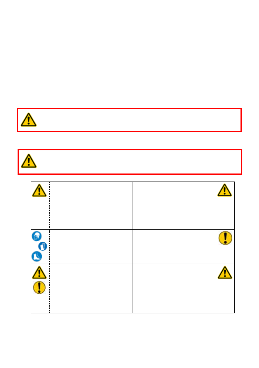
WARNING / CAUTION!
The operating instructions for the hoses, the accessories and the connected
devices must also be heeded!
Even if you have already received instructions on how to use the equipment, you should still
read the following safety notes again.
WARNING / CAUTION!
Ensure that the accessories and connected equipment used are suitable for
the maximum operating pressure!
Please ensure that no body
parts or clothing are caught
between the visibly moving
parts (e.g. piston protection
plate and cylinder).
Wear protective clothing,
safety helmet with visor,
safety shoes and protective
gloves
The responsible department
must be informed immediately
of any changes (including to
the operating behaviour)! If
necessary, the device must
be deactivated immediately
and secured!
It is prohibited to work under
loads if the load is lifted
exclusively by hydraulic
equipment. If this work
is absolutely imperative,
additional mechanical
supports must be used.
Inspect the equipment before
and after use for visible
defects or damage
Check all lines, hoses and
screwed connections for
leaks and externally visible
damage. Rectify any damage
immediately. Squirting
hydraulic uid can result in
injuries and res.
5
Page 6
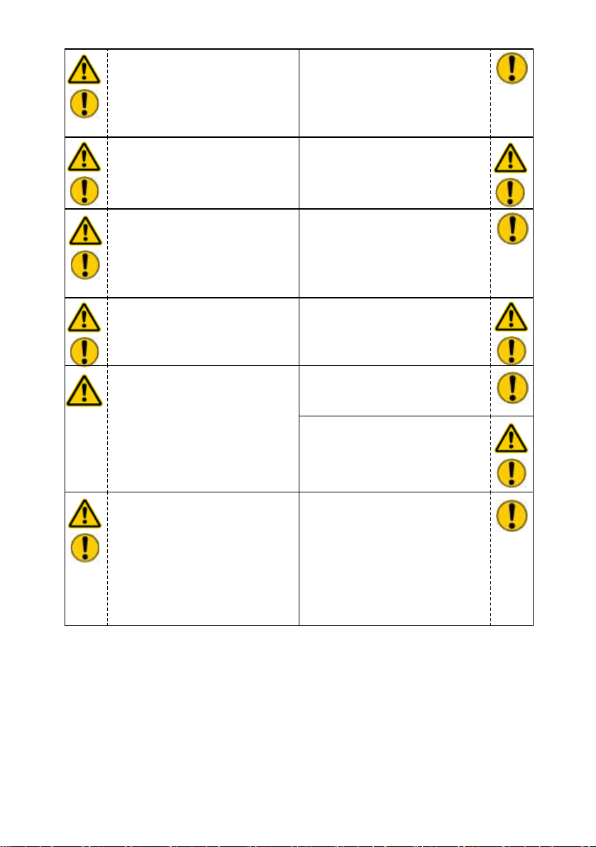
In the event of malfunctions,
immediately deactivate the
device and secure it. The
malfunction must be repaired
immediately.
Do not carry out any changes
(additions or conversions) to
the device without obtaining
the prior approval of LUKAS.
Observe all safety and danger
notes on the equipment and
in the operating instructions.
Any method of operation
which impairs safety and/or
stability of the equipment is
prohibited!
Safety devices must never be
deactivated!
Before the equipment is
switched on/started up, and
during its operation, it must
be ensured that nobody is
endangered by the operation
of the equipment.
When working close to live
components and cables,
suitable measures must
be taken to avoid current
transfers or high-voltage
ashovers to the equipment.
All safety instructions and
hazard warnings on the
device must be kept intact
and in a legible condition.
Comply with all specied
dates or dates specied in
the operating instructions
pertaining to regular checks /
inspections of the equipment.
The maximum permitted
operating pressure noted on
the equipment must not be
exceeded.
Only original LUKAS
accessories and spare parts
may be used for repairs.
Make sure that you do not
get caught in the hose loops
and trip when working with or
transporting the device.
Prevent electrostatic
discharge, which has the
possible consequence of
spark generation, when
handling the device.
6
Page 7
The device is lled with
hydraulic uid. These
hydraulic uids can be
harmful to your health if
swallowed or if their vapours
are inhaled. Direct contact
with the skin must be avoided
for the same reason. Please
note also that hydraulic uids
can have an adverse effect on
biological systems.
Ensure adequate lighting
when you are working.
When working with or storing
the equipment, ensure
that the function and the
safety of the equipment
are not impaired by the
effects of extreme external
temperatures and that the
equipment is not damaged in
any way. Please note that the
device can also heat up over
a long period of use.
Before transporting the
equipment, always ensure
that the accessories are
positioned such that they
cannot cause an accident.
Always keep these operating
instructions easily accessible
at the location where the
device is used.
The generally applicable, legal and other binding national and international regulations
pertaining to the prevention of accidents and protection of the environment apply and
must be implemented in addition to the operating instructions.
Make sure you dispose of
all parts removed, oil and
uid residues and packaging
materials in a proper manner!
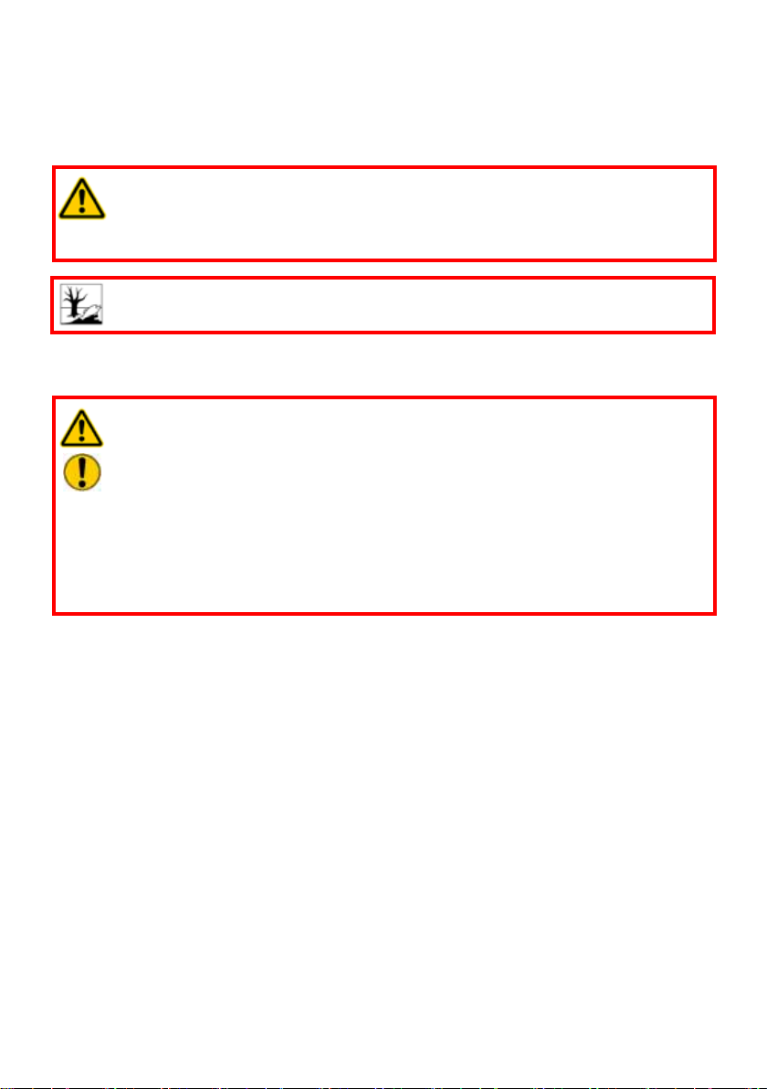
WARNING / CAUTION!
The equipment is to be used exclusively for the purpose stated in the operating
instructions (see chapter “Intended use”). Any other or further use is not considered
Intended use. The manufacturer / supplier is not liable for any damages resulting from not
intended use. The user bears sole responsibility for such.
Observance of the operating instructions and compliance with the inspection and maintenance
conditions are part of the Intended use.
Never work when you are overtired or intoxicated!
7
Page 8
3. Intended use
LUKAS hydraulic cylinders are designed specially for use in lifting and displacing work, use
in assembly and in service work.
In general, LUKAS hydraulic cylinders can be used to lift, push or relocate objects.
WARNING / CAUTION!
All objects which are to be moved must be secured using stable supports or
substructures. In addition, you have to make sure that the hydraulic cylinders
cannot slip.
CAUTION!
Pay strict attention to leaks in order to prevent threats to the environment.
Every time you use the equipment, make sure that the necessary accessories, such as the
piston protection plate etc., are used.
WARNING / CAUTION!
The following may not be crushed or damaged:
- live cables
- hardened parts such as steering columns and rollers
- Explosive objects, such as air bag cartridges and pressurised gas
cylinders
NEVER operate the hydraulic cylinders at a higher operating pressure than
shown on the identication plate. A higher setting may cause damage to property
and/or injuries.
Genuine spare parts, accessories for the equipment and suitable hydraulic uids can be
ordered from your authorised LUKAS dealer!
8
Page 9
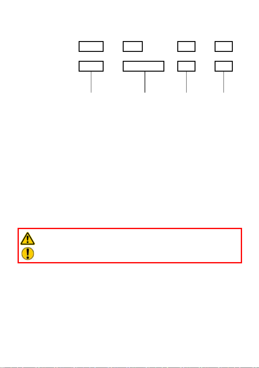
4. Equipment designation
single-acting
cylinders:
double-acting
cylinders:
LFO 55 / 200 Z
HLMD 55 - 25 / 200 M
Cylinder range Cylinder type Stroke Connection
thread for
couplings
Coupling connection thread:
M = metric thread
Z = inch thread
5. Functions and performance
5.1 Description
LUKAS hydraulic cylinders can be either single or double acting. This can be seen in the
designation of the cylinder.
The movement of the piston when extending is carried out hydraulically for both cylinder
types. When retracting, only the double acting cylinders move under hydraulic force. On
single acting cylinders it takes place mechanically, e.g. by a release spring. Single acting
cylinders can also be equipped without release springs, and the retraction is actuated by the
lifted load which acts on the piston of the cylinder when the pressure is removed.
WARNING / CAUTION!
Please take care that single acting cylinders can move unexpectedly if the
pressure is removed and the line to the cylinder is not closed off!
The direction of movement is controlled by the application of pressure to the rod side of
the piston (only on double acting cylinders) or to the cylinder base side. The control of
the pressurisation must be effected by an external control unit (e.g. a control valve) and
a hydraulic aggregate connected to it. The use of a hand pump instead of the hydraulic
aggregate is also possible.
In general, all LUKAS double acting cylinders are equipped with an integrated safety valve on
the piston rod side. These safety valves protect the cylinder from damage caused by pressure
transmission. If the specied maximum pressure is exceed, the safety valves automatically
open and hydraulic oil (shielded) is ejected into the open air.
9
Page 10
LUKAS offers hydraulic cylinders in a wide variety of designs.
Depending on the type, the cylinders are made of different materials such as aluminium alloy, steel or stainless steel. The types of cylinder also vary by method of construction. They
are available as normal lifting cylinders, heavy duty, short stroke, locking and at cylinders.
Depending on the version, they can be used in a wide range of different applications.
If you have any doubts as to whether the cylinder you have selected is suitable for the
application in question, please consult LUKAS directly or one of the authorised LUKAS
dealers.
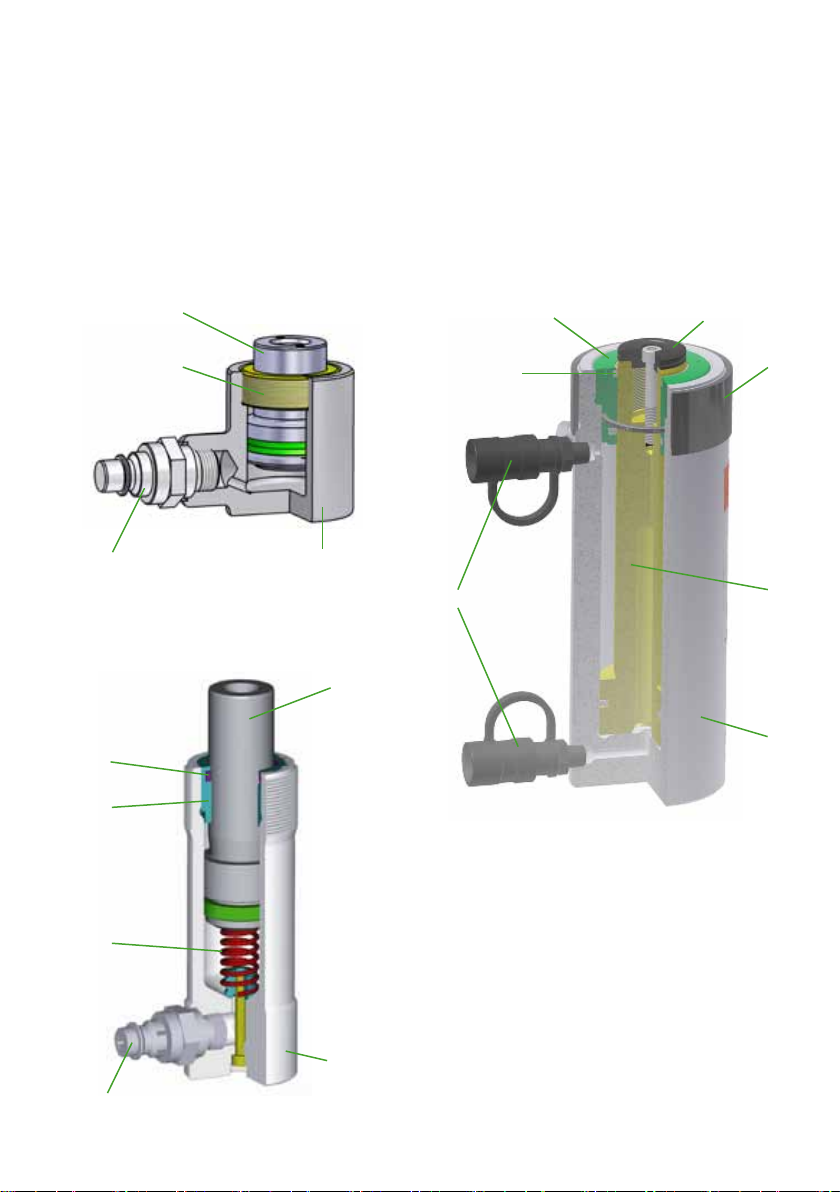
5.2 Basic construction of the cylinder
2
3
6
3
8
5
3
4
1
8
2
1 Cylinder body
2 Piston
3 Guiding ring
4 Piston return
5 Wiper
6 Piston protection plate
7 Thread protection ring
8 Connection coupling
1
(plug or screw coupling)
5
7
2
1
8
10
Page 11

5.3 Controlling the operating movements
5.3.1 Single acting hydraulic cylinders (with release spring)
The piston is extended by pressurising the connection (1) on the cylinder base
side (3). The piston retracts again using the release spring (2) as soon as the
pressure on the connection (1) is released and the pressure can dissipate
through the supply line (not closed off and not under pressure).
2
1
5.3.2 Single acting hydraulic cylinders (without release spring)
The piston is extended by pressurising the connection (4) on the cylinder base side (5).
After the pressure is released, the piston retracts solely as a result of the force of an external
load, provided the pressure can dissipate via the supply line (not closed off and not under
pressure).
4 4
5
2
1
3
11
Page 12

5.3.3 Double acting hydraulic cylinders
Pressurisation of the connection (6) on the cylinder base
side (7) causes the piston rod to extend and pressurisation
of the connection (8) on the piston rod side (9) causes the
piston rod to retract again.
9
9
8
6
8
6
7
5.4 Hydraulic supply
A LUKAS hydraulic unit or LUKAS hand pump may be used to drive the equipment.
If the pump unit is a different make, you must make sure that it complies with LUKAS
specications, otherwise potential dangers may arise which are not the responsibility
of LUKAS. Ensure in particular that the maximum permissible operating pressure for the
connected LUKAS equipment is not exceeded.
NOTE:
Before you use pumps from a different manufacturer, we recommend you
contact LUKAS or an authorised dealer. Otherwise LUKAS will accept no liability
for any damage caused.
The pump aggregate and the hydraulic cylinder are interconnected by hoses or pipework.
12
Page 13

6. Connecting the equipment
6.1 Hydraulic connections
On the side of the hydraulic cylinders are male Quick-disconnect connectors or female
screwed couplings; these are connected to the hydraulic source or control valve with
extension hoses or pipework.
Use LUKAS pairs of extension hoses which are generally colour-coded and fitted with
couplings so that they can be connected non-interchangeably.
WARNING / CAUTION!
Prior to connecting the devices, ensure that all the components
being used are suitable for the maximum operating pressure
of the pump unit. In case of doubt you must consult LUKAS
directly.
CAUTION!
Make sure that the connection on the cylinder base side is always connected
to the connection provided on the control valve for extending the cylinder,
and that the connection on the cylinder head (cylinder piston rod side) is
connected to the connection for retracting the cylinder.
6.2 Coupling the screwed couplings
The cylinder is connected to the hydraulic pump via screwed coupling halves (male and
female).
Remove the dust caps before coupling, then plug the male connector on the hose into
the female connector on the side of the cylinder. Finally screw the threaded sleeve on the
female connector onto the external thread on the male connector and tighten hand-tight.
The connection is now made.
Uncoupling is carried out in the reverse sequence. For dust protection, the supplied dust caps
must be reattached.
WARNING / CAUTION!
Coupling of the devices is only possible when the hoses are depressurised!
13
Page 14

CAUTION!
Always connect the hose to the connection on the cylinder head (cylinder
piston rod side) rst and then connect the hose to the connection on the base
of the cylinder!!
6.3 Coupling Quick-disconnect Couplings
The cylinder is connected to the hydraulic pump via Quick-disconnect coupling halves (male
and female).
X
Y
Before coupling, remove the dust caps then pull back and hold the locking sleeve on the
female half (position X). Plug the male and female halves together and release the locking
sleeve. Then turn the locking sleeve to position Y. The connection is now made and secured.
Uncoupling is carried out in the reverse sequence. Hoses can be connected only when
depressurised. For dust protection, the supplied dust caps must be reattached.
CAUTION!
Always connect the hose to the connection on the cylinder head (cylinder
piston rod side) rst and then connect the hose to the connection on the base
of the cylinder!!
NOTE:
Hoses can be connected only when depressurised.
For dust protection, the supplied dust caps must be reattached.
WARNING / CAUTION!
To some extent the quick-disconnect coupling have special functions and may
therefore not be unscrewed from the hydraulic lines and/or swapped!
14
Page 15

7. Operation
7.1 Basic selection of cylinder size
Before use, you should check that the lifting force of the cylinder(s) used is at least 25%
higher than the maximum loading expected in the least favourable case.
WARNING / CAUTION!
The load must NEVER exceed the lifting force of the cylinder!
We recommend that you select the stroke of the piston to leave a reserve stroke of approx.
30%. The system stability can thus be increased in marginal cases.
7.2 Positioning
CAUTION / PLEASE NOTE!
Prior to installing the cylinders, the load to be lifted must be secured against
slipping as prescribed in the respective applicable guidelines and regulations.
You must always observe the following when positioning the cylinder:
- Non-slip and at surface underneath, so that the entire cylinder base area is supported.
If there is any doubt about the load bearing capacity of the ground you should use suitable
plates made from wood or metal to increase the area of support.
WRONG RIGHT
CAUTION!
Hydraulic uids may produce a lubricating lm on the oor.
15
Page 16

- The ground must be a continuous surface (no gratings, gravel etc.)
- Never place cylinders on a yielding support
WARNING / CAUTION!
When using wooden packers, you should make sure that you use particularly
hard wood without any damage, so that splintering of the packer is not
possible. Additional strapping of other types of wood with metal straps is not
adequate!
- We recommend using the cylinders only with a piston protection plate to prevent damage
to the piston and to ensure safe application of the force. LUKAS accepts no liability for
damage which could have been prevented by the use of a piston protection plate!
Suitable piston protection plates for your application can be found in the LUKAS range of
accessories.
CAUTION!
Use an additional non-slip packer between the piston protection plate and
the load to be lifted because there may be a lm of lubricant on the point of
application of the load!
16
Page 17

- Please make sure that the load is applied centrally onto the piston rod.
NOTE:
Under certain circumstances it may be necessary to nd a more favourable
load application point!
Position the cylinder under the gravity center of the load, so that the load does not tip
over during lifting, thus causing danger to the operator or the cylinder itself. The load
must always be centrally located on the piston area. Side loading should be avoided!
Load
WRONG RIGHT
It is mostly not possible to allow the load to lie over the full face of the cylinder piston.
For this reason, we recommend using appropriate piston protection plates because
otherwise there may be damage caused to the piston rod and the cylinder. A bowed
piston protection plate or an equalisation plate re-distributes the load evenly on the
surface of the piston.
Load
WRONG
Load
Load
RIGHT
17
Page 18

When using several pistons at the same time, you should distribute the load as evenly
as possible over all the cylinders.
Load
share 1
Load share 1 < Load share 2
WRONG RIGHT
When using several pistons at the same time, you should lift the load as evenly as
possible using all the cylinders.
WRONG
Load
share 2
Load
share 1
Load share 1 = Load share 2
RIGHT
7.3 Commissioning
Load
share 2
WARNING / CAUTION!
Always keep a safe distance from the hydraulic cylinder when you pressurise it,
particularly when starting up after positioning the equipment!
CAUTION!
Always check, before each start-up, that the hydraulic connections are correctly
made and that they are functioning perfectly.
Incorrect connections or defective couplings can cause a safety valve to
respond (e.g. on double acting cylinders on the piston rod side or on hoses
with safety Quick-disconnect connectors on the male coupling!)
18
Page 19

7.3.1 Initial start-up
The equipment must be de-aerated before commissioning and following repairs.
- Connect the equipment to the hydraulic pump (see chapter “Connecting the equipment”).
- Extend and retract the equipment several times under no load.
NOTE:
We recommend that during the de-aeration, the unit connected for the hydraulic
supply should stand on a higher level than the cylinder.
The connections on the hydraulic cylinder should point upwards.
7.3.2 Checking the pump unit
See the separate operating instructions for the relevant aggregate (or the
handpump).
NOTE:
Before working on the pump aggregate or connecting/disconnecting hoses,
always make sure that the pump aggregate or electric pump is switched off and
disconnected from the electricity supply and that the control valves have been
set to depressurised recirculation.
7.4 Hydraulic control of the cylinder
The operation of the cylinder piston cannot be controlled directly by the cylinder.
The retraction and extension of the cylinder must be controlled by a separate control unit or
by the connected hydraulic unit.
19
Page 20

8. Dismantling the equipment / deactivation following
operation
WARNING / CAUTION!
Before dismantling the used equipment, you must ensure that the load being
moved is in a stable, non-slip location!
8.1 Hydraulic cylinder
After the work is completed the hydraulic cylinders should be retracted to leave just a few
*)
mm
protrusion (up to the end position on single acting cylinders). This relieves the hydraulic
and mechanical strain on the device.
NOTE:
When hydraulic cylinders are in storage, uctuations in ambient temperature can
cause the pistons to move slightly. This phenomenon is due to the difference in
the expansion of the hydraulic uid on the piston side and the rod side.
8.2 Hydraulic unit
Upon completion of work, the unit must be deactivated.
8.3 Hoses
Uncoupling is carried out in the reverse order, as described in Chapter “Connecting the
Equipment”.
Ensure that you replace the dust protection caps on the Quick-disconnect coupling halves.
*)
1 mm = 0.04 in.
20
Page 21

9. Care and Maintenance
A visual inspection must be carried out after every use; however, at least one visual inspection
must be carried out every year. Every three years or if there is any doubt regarding the safety
or reliability of the equipment, a functional test must also be performed. (Please also observe
the relevant valid national and international regulations pertaining to service intervals of
hydraulic equipment).
CAUTION!
Clean off any dirt before checking the equipment!
WARNING / CAUTION!
To perform maintenance and repairs, workshop and personal safety equipment
appropriate for the work is an absolute requirement
Inspections to be carried out:
Visual inspection
• Cylinder and piston rod undamaged and not deformed,
• Connections without damage or deformation
• General tightness (no leaks)
• All screwed connections tight
• Couplings present and tightened,
• Couplings easy to couple,
• Dust protection caps available
• Type plate, warning notices and other markings present and legible
• All used accessories undamaged
Functional test
• Piston can be retracted and extended over the full length of the stroke (see Chapter
“Technical Data”).
• Easy and smooth extension and retraction when pressurized.
• No suspicious noises when operating.
21
Page 22

10. Repairs
10.1 General information
Service work may only be performed by the device manufacturer or by personnel trained by
the device manufacturer and authorised LUKAS dealers.
Only LUKAS spare parts may be used to replace all components (see spare parts list) since
special tools, assembly instructions, safety aspects, inspections will have to be taken into
account (see also chapter „Maintenance and service”).
During assembly work, pay particular attention to the cleanliness of all components
because dirt can damage the equipment!
WARNING / CAUTION!
Protective clothing must be worn when repairs are being carried out, since the
units can also be pressurised when in an idle state.
NOTE:
Before you use couplings from a different company, you must always contact
LUKAS or an authorized dealer.
Do not perform any repairs without the corresponding LUKAS spare parts list,
because necessary tightening torques for screw connections and/or in some
cases also important additional information are listed there.
CAUTION!
Since LUKAS hydraulic cylinders are designed for top performance, only those
components in the spare parts lists for the relevant unit may be replaced.
Other components on the cylinders may only be replaced if:
- you have taken part in appropriate LUKAS service training,
- you have the explicit permission of the LUKAS Service department (After
request, check for the granting of permission. A check is necessary in each
individual case).
When cleaning the equipment, take care not to use any cleaning agent that has
a pH value outside the range 5 - 8!
The address of LUKAS Customer Service can be found in the Chapter “Fault Analysis”.
Genuine spare parts, accessories for the equipment and suitable hydraulic uids can be
ordered from your authorised LUKAS dealer!
10.2 Preventive maintenance
10.2.1 Care instructions
The exterior of the equipment must be cleaned from time to time in order to protect it from
external corrosion. A suitable agent must be applied to the metallic surfaces.
(In case of doubt, contact your authorised LUKAS dealer or LUKAS directly!)
22
Page 23

10.2.2 Function and load test
Perform a stress test if there is doubt about safety or reliability.
10.2.3 Replacingthehydraulicuid
- After approx. 200 deployments, but after three years at the latest, replace the hydraulic uid
CAUTION!
Always carry out the hydraulic uid change using a uid collection vessel and
dispose of the uid collected in a proper manner!
CAUTION!
The hydraulic uid must be completely replaced if the deployment
conditions (ambient temperatures) change considerably. When selecting the
appropriate hydraulic uid, please bear in mind the Chapter “Hydraulic Fluid
Recommendations”.
Procedure:
1. Retract the cylinder completely and depressurise the hydraulic system.
2. Remove the couplings from the cylinder.
3. Allow the hydraulic uid to run out
4. Flush
5. Ret the couplings
6. Connect the pump with new hydraulic uid.
7. Bleed as described in chapter “Initial Commissioning”.
8. Disconnect the pump again.
10.3 Repairs
10.3.1 Changing the seals
The seals must be replaced in the event of:
- Leaks,
- Externally visible damage (e.g. on the wiper),
WARNING / CAUTION!
Work on the internals of the cylinder, e.g. changing the seals, must only be
carried out by trained experts!
All parts must be replaced by genuine LUKAS parts!
NOTE:
Changing the seals is similar on all types of cylinder.
However, there are differences resulting from the type of cylinder and the size.
For this reason, it is absolutely imperative that you always have the appropriate
spare parts list for your cylinder to hand when carrying out a repair. All instructions
on the spare parts list must be taken into account as well as these operating
instructions!
23
Page 24

Procedure:
1. First, fully retract the cylinder and switch the hydraulic system to depressurised.
2. Then, on double acting cylinders, extend them by approx. 10 mm, without load.
This hydraulically depressurises them.
3. Uncouple the hydraulic pump.
4. Place the cylinder in a suitable vessel or on a suitable substrate to collect the hydraulic
uid that comes out.
5. Remove all attachments such as piston protection plates (if tted).
6. Now you will have to remove the couplings.
7. Release the guiding ring on the cylinder head.
WARNING / CAUTION!
With single acting cylinders with release spring please note that the
spring may remain under tension and take the appropriate precautionary
measures.
8. Pull the guiding ring from the piston rod.
24
Page 25

9. You can now remove the seals from the guiding ring using a suitable tool.
CAUTION!
Do not damage the guiding ring when removing the seals!
10. Carefully pull the piston out of the cylinder body!
On single acting cylinders with release spring, you must rst separate the release spring
from the cylinder body. This normally carried out by removing the xing screw and the
sealing ring. On single acting cylinders, the release spring is equipped with such a xing
screw on the bottom of the cylinder body and on the cylinder head. You should remove
the screw on the cylinder body bottom rst.
CAUTION!
Make sure that you do not tilt the piston when pulling it out! That could cause
damage to the piston and the cylinder body!
11. Now you can remove the seals from the piston using a suitable tool.
12. The assembly is carried out in reverse order.
NOTE:
During assembly, brush the seals with LUKAS special grease. This simplies
the assembly of the seals and increases the operating life!
13. The cylinder must then be deaerated!
25
Page 26

10.3.2 Couplings
The couplings must be replaced if:
- there is external damage
- the locking mechanism does not work
- hydraulic uid continues to leak in the coupled/uncoupled state.
WARNING / CAUTION!
Never repair couplings: they must be replaced by original LUKAS parts!
During assembly, tighten the coupling to the torque that is quoted in the relevant spare parts
list for the cylinder.
Procedure:
1. Remove the coupling.
2. Position the new coupling and tighten to the torque quoted in the relevant spare parts list
of the cylinder.
10.3.3 Labels
All damaged and/or illegible labels (safety notices, type plate etc.) must be replaced.
Procedure:
1. Remove damaged and/or illegible labels.
2. Clean surfaces with industrial alcohol.
3. Attach new labels.
Ensure that you attach the labels in the right position. If this is no longer known, you should
ask your authorised LUKAS dealer or contact LUKAS directly.
11. Troubleshooting
Trouble Check Cause Solution
Cylinder piston
moves slowly or
jerkily when activated
Are the hoses
connected
properly?
Does the pump
unit work?
Air in the hydraulic
system
Cylinder defective Remove the cylinder
26
De-aerate pump
system
from service and
have it repaired or
repair it
Page 27

Trouble Check Cause Solution
Piston on cylinder
(with Quickdisconnect coupling
system) does not
retract
Device does not
apply the specied
force
Hose assembly
cannot be coupled
Hydraulic uid leak
on the hoses or the
connections
Damage to the
surface of the
hydraulic hoses
Hydraulic uid leaks
on the piston rod
Hydraulic uid
level in the
supplying pump?
Check the
operating pressure
of the driving
hydraulic unit
Are the hoses
defective?
Quick stop
function on
cylinder effective
Cylinder defective Remove the cylinder
Insufcient
hydraulic uid in
the pump
Pressure of supply
too low
Cylinder defective Remove the cylinder
Pressurised Set hydraulic pump
Coupling defective Coupling needs to be
Leakage, possible
damage
Mechanical
damage or contact
with aggressive
agents
Defective rod seal Repair of fault by
Damage to the
piston
Extend the cylinder
piston a short
distance and then
retract the cylinder
piston slowly.
from service and
have it repaired or
repair it
Top up hydraulic uid,
de-aerate
If possible, increase
the max. operating
pressure on the
hydraulic unit to
the max. operating
pressure of the
cylinder or use a
different hydraulic
unit with adequate
max. operating
pressure.
from service and
have it repaired or
repair it
to pressureless
circulation
replaced immediately
Replace hoses.
Replace hoses.
authorised dealer,
specially trained
LUKAS staff or
directly by LUKAS
27
Page 28

Trouble Check Cause Solution
Hydraulic uid
coming out of overpressure valve
Increased load?
(only when pulling)
Load increase
(e.g. something
has fallen onto the
part to be pulled,
thereby suddenly
increasing the
load)
Secure the loads and
move them by using
other tools
Apply the cylinder at
another point where
the load to be moved
is lighter
Use supporting
equipment to move
the load.
Coupling on the
cylinder piston
side correctly
coupled or
defective?
Leak in the couplings Is the coupling
If it isn’t possible to rectify the malfunctions, inform an authorised LUKAS dealer or the
LUKAS customer service department immediately!
The address of the LUKAS Customer Service Department is:
LUKAS
Weinstrasse 39, D-91058 Erlangen
Germany
Phone: (+49) 09131 / 698 - 348
Fax.: (+49) 09131 / 698 - 353
e-mail: lukas.info@idexcorp.com
Hydraulik GmbH
damaged?
Coupling on the
cylinder piston
side not coupled
or coupled
incorrectly
Coupling on the
cylinder piston
side defective
Coupling defective Coupling must be
Reconnect the
coupling
Coupling must be
replaced immediately
replaced immediately
28
Page 29

12. Technical data
12.1 Cylinder data
NOTE:
The technical data for your cylinder can be found on the provided, separate
datasheet. This datasheet also includes the CE declaration.
12.2 Hydraulicuidrecommendations
Mineral oil DIN ISO 6743-4 for LUKAS hydraulic equipment and others
Oil temperature range Oil code Viscosity rating Remarks
A -24 .... +30°C HL 5 VG 5
B -18 .... +50°C HM 10 VG 10
C -8 .... +75°C HM 22 VG 22
D +5 .... +80°C HM 32 VG 32
E -8 .... +70°C HF-E15 VG 15 Bio-oil
Oil temperature range Oil code Viscosity rating Remarks
A -11.2 .... +86°F HL 5 VG 5
B -0.4 .... +122°F HM 10 VG 10
C +17.6 .... +167°F HM 22 VG 22
D +41.0 .... +176°F HM 32 VG 32
E +17.6 .... +158°F HF-E15 VG 15 Bio-oil
recommended viscosity range: 10...200 mm²/s (10…200 cSt.)
Supplied with HM 10 DIN ISO 6743-4.
NOTE:
The hydraulic uids listed here are the standard oils which could be used for
your LUKAS cylinder.
Special cylinders may be designed to use different special hydraulic uids.
Details of these uids can be found on the separate datasheet for your cylinder.
TheuseofdifferenthydraulicuidstooperateyourLUKAScylindersispossible
but will need approval by LUKAS directly in each particular case!
29
Page 30

13. Notes
30
Page 31

31
Page 32

Please dispose all packaging materials and
dismantled parts properly.
LUKAS
A unit of the IDEX Corporation
Hydraulik GmbH
Weinstrasse 39, D-91058 Erlangen
Germany
Phone: (+49) 0 91 31 / 698 - 0
Fax.: (+49) 0 91 31 / 698 - 394
e-mail: lukas.info@idexcorp.com
www.lukas.com
Made in GERMANY
© Copyright 2011 LUKAS Hydraulik GmbHZylinder_BA_GB_83145000085_0811.indd
Subject to revision
 Loading...