

Operating Instructions -
Re-railing Technology
HP Cylinders
(Translation of the original operating instructions)
84072376585 GB
Edition 12.2011

2

Contents Page
1. Hazard classes 4
2. Product safety 5
3. Proper use 8
4. Device designation 9
5. Functions and performance 9
5.1 Description 9
5.2 Controlling the operating movements 10
5.3 Hydraulic supply 10
5.4 Hose lines 10
6. Connecting the equipment 11
6.1 Hydraulic 11
6.2 Coupling quick-disconnect couplings 11
7. Operation 12
7.1 Installation 12
7.2 Commissioning 14
7.3 Hydraulic cylinder control 15
8. Use of accessories 16
8.1 Base plate 16
8.2 Multistage sets 16
9. Dismantling the device / deactivation following operation 20
9.1 Hydraulic cylinder 20
9.2 Hydraulic unit 20
9.3 Hose lines 20
10. Maintenance and service 21
11. Repairs 22
11.1 General 22
11.2 Preventive maintenance 23
11.3 Repairs 24
12. Troubleshooting 25
13. Technical Data 27
13.1 Cylinder data 28
13.2 Hydraulicuidrecommendations 30
13.3 Operating and storage temperature ranges 30
14. EC Declaration of Conformity 31
15. Notes 32
3
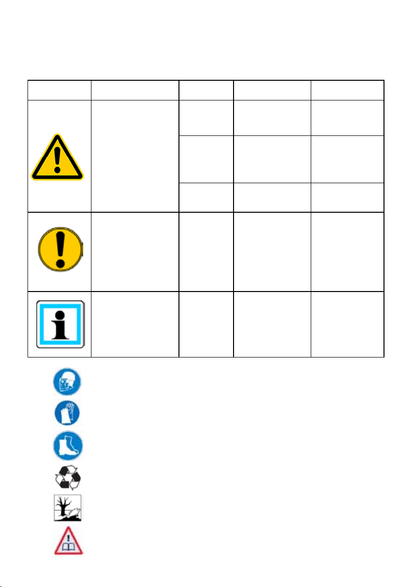
1. Hazard classes
We distinguish between various categories of safety notes. The table below provides an
overview of the assignment of symbols (pictograms) and signal words to the specic danger
and the possible consequences.
Pictogram Damage / injury to Key word Denition Consequences
DANGER! Immediate danger
human
device
- NOTE
Wear a helmet with face protection
WARNING!
CAUTION!
CAUTION!
Potentially
dangerous
situation
Less dangerous
situation
Danger of damage
to device /
environment
Advice for
application and
other important /
useful information
and advice
Death or major
injury
Potential death or
major injury
Minor or slight
injury
Damage to the
equipment,
damage to the
environment,
damage to
surrounding
materials
No injury /
damage to
persons /
environment /
equipment
Wear safety gloves
Wear safety shoes
Proper recycling
Observe principles of environmental protection
Read and observe operating instructions
4
2. Product safety
LUKAS products are developed and manufactured to guarantee the best performance and
quality when used properly.
The safety of the operator is the most important consideration in product design. Moreover,
the operating instructions are intended to aid the safe use of LUKAS products.
The generally applicable, legal and other binding regulations pertaining to the prevention of
accidents and protection of the environment apply and are to be implemented in addition to
the operating instructions.
The equipment may only be operated by persons with appropriate training in the safety
aspects of such equipment – otherwise, there is a danger of injury.
We would like to point out to all users that they should carefully read and adhere to the
operating instructions in full before they use the equipment.
We further recommend that a qualied trainer train you in the use of the product.
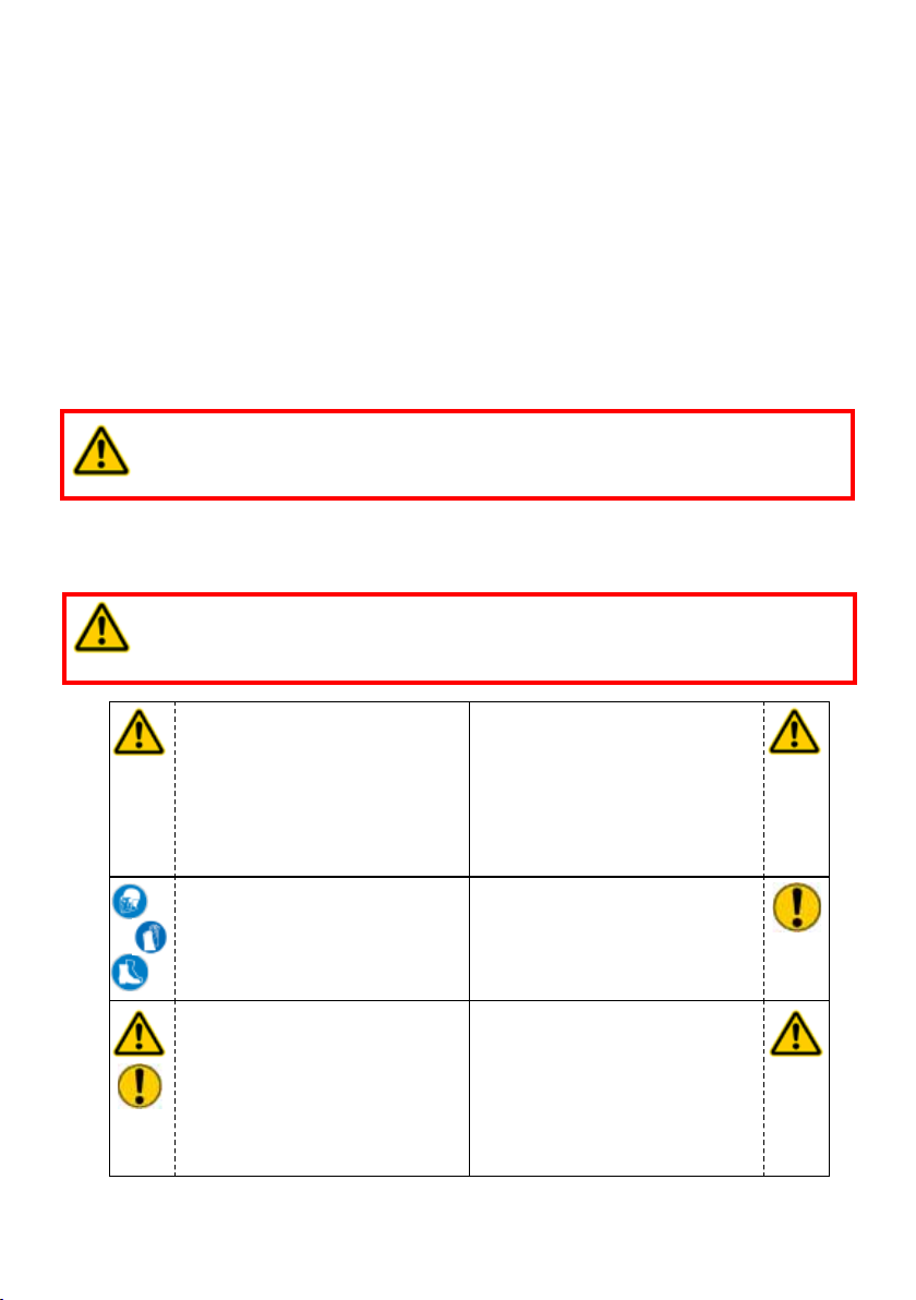
WARNING / TAKE CARE!
The operating instructions for the hoses, the accessories and the connected
hydraulic equipment must also be observed!
Even if you have already received instructions on how to use the equipment, you should still
read the following safety notes again.
WARNING / TAKE CARE!
Ensure that the accessories used and the connected equipment are suitable
for the maximum operating pressure!
Please ensure that no body
parts or clothing are caught
between the visibly moving
parts (e.g. piston guard plate
and cylinder).
Wear protective clothing,
a safety helmet with visor,
protective footwear and
gloves
The responsible department
must be informed immediately
of any changes (including to
the operating behaviour)! If
necessary, the device must
be deactivated immediately
and secured!
Working under loads is
prohibited if they are raised
exclusively with hydraulic
devices. If this work is
unavoidable, adequate
mechanical supports are
additionally required.
Inspect the device before and
after use for visible defects or
damage
Inspect all cables, hoses
and screwed connections
for leaks and externally
visible damage! If necessary,
repair immediately! Squirting
hydraulic uid can result in
injuries and res.
5
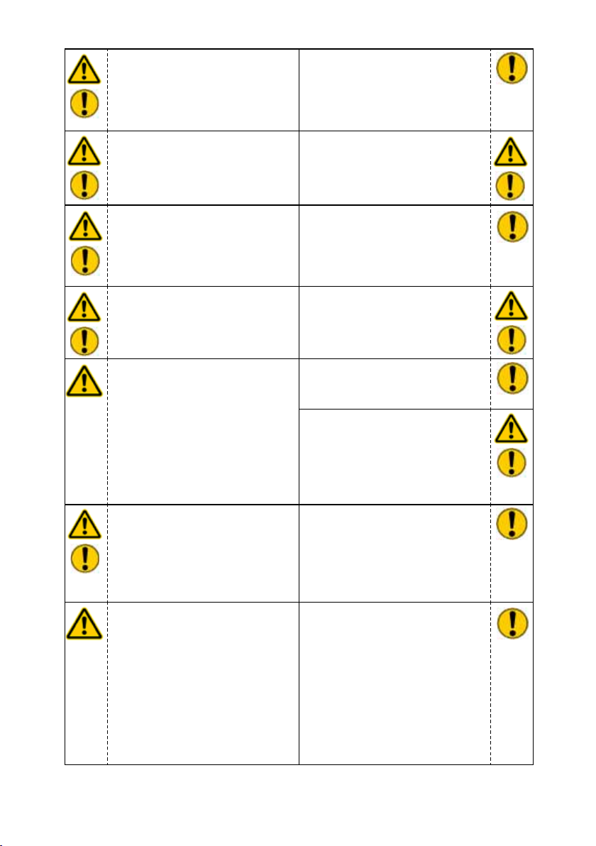
In the event of malfunctions,
immediately deactivate the
device and secure it. You
should have the malfunction
repaired immediately.
Observe all safety and danger
notices on the device and in
the operating instructions.
Do not carry out any changes
(additions or conversions) to
the device without obtaining
the prior approval of LUKAS.
All safety and danger notices
on the device must be kept
complete and in a legible
condition.
Any mode of operation which
impairs safety and/or stability
of the device is forbidden!
Safety devices must never be
disabled!
Before the device is switched
on / started up, and during its
operation, it must be ensured
that nobody is endangered by
the operation of the device.
When working in the proximity
of live components and wires,
appropriate steps must be
taken to avoid current ow
or high-voltage discharge
through the device.
The device is lled with a
hydraulic uid. These hydraulic
uids can be harmful to your
health if swallowed or if their
vapours are inhaled. Direct
contact with the skin should
be avoided for the same
reason. Please also note that
hydraulic uids can also have
an adverse effect on biological
systems.
Comply with all stipulated
dates or dates specied in
the operating instructions
pertaining to regular tests /
inspections on the equipment.
The maximum permitted
operating pressure noted on
the equipment must not be
exceeded.
Only original LUKAS
accessories and spare parts
may be used for repairs.
Please ensure that, when
working with this equipment
or during transportation of
such, you do not become
entangled in the looped hoses
and trip.
The build-up of static
charge with the potential
consequence of spark
formation is to be avoided
when handling the device.
When working with or storing
the equipment, ensure that the
function and the safety of the
equipment are not impaired by
the effects of extreme external
temperatures and that the
equipment is not damaged in
any way. Please note that the
device can also heat up over a
long period of use.
6
Ensure adequate lighting when
you are working.
Always keep these operating
instructions within reach where
the device is used.
The generally applicable, legal and other binding national and international regulations
pertaining to the prevention of accidents and protection of the environment apply and are to
be implemented in addition to the operating instructions.
Before transporting the
device, always ensure that the
accessories are positioned
such that they cannot cause an
accident.
Dispose properly of all
disassembled parts, oil and
left-over uid, as well as
packaging materials.
WARNING / CAUTION!
The equipment is intended to be used exclusively for the purpose stated in the operating
instructions (see chapter “Proper Use”). Any other or further use is not considered
proper use. The manufacturer/supplier is not liable for any damages resulting from improper
use. The user bears sole responsibility for such.
Observance of the operating instructions and compliance with the inspection and maintenance
conditions are part of the proper use.
Never work when you are overtired or intoxicated!
7
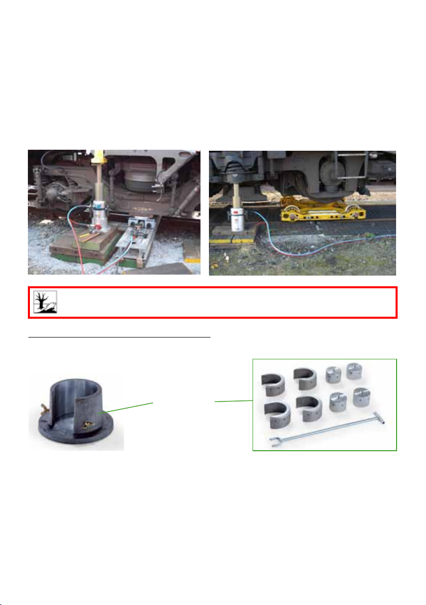
3. Proper use
LUKAS-HP cylinders are especially designed for re-railing technology. In the event of derailed rail vehicles, they are used to lift the vehicles so that they can be re-railed, e.g. with an
additional transfer unit. Furthermore, they can be used to lift a rail vehicle in order to push a
towing device underneath it, for example.
HP cylinders in telescopic design offer long hoisting paths with a low retracted overall
height.
The accessories necessary for the particular application, such as base plate, multistage sets
etc., must be used during each deployment.
CAUTION!
Watch out vigilantly for any leaks in order to avoid threats to the environment.
Recommended accessories for HP cylinders:
- Base plate (Item 1)
- Multistage set (Item 2)
1 2
8

4. Device designation
Cylinder variant
25 THP 700
Design
Cylinder type
Cylinder variant:
HP = High pressure cylinder
Design:
(no information) = Single-stage design
T = Telescopic design
Special feature:
R = Hydraulic retraction
Total stroke
in [mm]
R/
Special
feature
5. Functions and performance
5.1 Description
HP cylinders are double-acting hydraulic cylinders. Extension and retraction takes place
hydraulically. The direction of movement is controlled by pressurising the piston rod side or
the cylinder base side. Control of the pressurisation must be effected by an external control
unit (e. g. control panel) and a connected hydraulic unit (the use of a hand pump is possible
in exceptional cases).
Securing against unwanted lowering of the cylinders in the event of a hose breakage is
achieved by means of quick-stop couplings tted to the hose. If there is any doubt as to
which coupling sleeves are tted to your hose, please contact your authorised LUKAS dealer
or LUKAS directly before using the hose.
In addition to the quick-disconnect couplings, the HP cylinders are additionally equipped with
two connection blocks with integrated safety valve. These safety valves protect the cylinder
from damage caused by sudden load increase (e.g. something has additionally fallen onto
the part to be lifted, thus suddenly increasing the weight). If the specied maximum pressure
is exceed, the safety valves automatically open and hydraulic uid (protected) is squirted
out.
HP cylinders in telescopic design offer long hoisting paths with a low retracted overall
height.
9
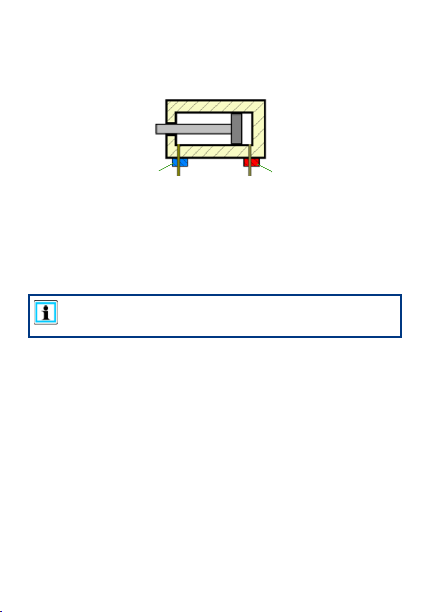
5.2 Controlling the operating movements
When the valve (A) is pressurised on the cylinder base side, the piston rod is extended. By
pressurising valve (B) on the piston rod side the piston rod retracts again.
B
A
5.3 Hydraulic supply
Only LUKAS motor pumps (or hand pumps in exceptional cases) may be used to drive the
devices.
If the pump unit is of a different make, you must make sure that it complies with LUKAS
specications, otherwise hazards may occur which are not the responsibility of LUKAS.
Ensure in particular that the maximum permissible operating pressure for the connected
LUKAS equipment is not exceeded.
NOTE:
Before you use pumps from a different manufacturer, you must contact LUKAS
or an authorised dealer.
5.4 Hose lines
The pump unit and the HP cylinder are connected by hoses.
10

6. Connecting the equipment
6.1 Hydraulic
On the device side, a quick-disconnect coupling sleeve is provided on the piston rod side of
the valve, and a quick-disconnect coupling nipple on the cylinder base side of the valve; they
are connected to the pump unit via two extension hoses.
All LUKAS pairs of extension hoses are colour coded and are equipped with quick-disconnect
couplings so that they cannot be mixed up when being connected.
WARNING / CAUTION / ATTENTION!
Prior to connecting the devices, ensure that all the components
being used are suitable for the maximum operating pressure
of the pump unit. In the case of doubt you must consult LUKAS
directly!
6.2 Coupling quick-disconnect couplings
The equipment is connected to the hydraulic pump via quick-disconnect-coupling halves
(male and female).
X
Y
Before coupling, remove the dust protection caps and then pull back and hold the locking
sleeve of the female coupling half (position X). Connect the male and female coupling together
and release the locking sleeve. Then turn the locking sleeve to position Y. The connection has
now been made and locked. Disconnection is carried out in the reverse order. Hoses can be
connected only when depressurised. For dust protection, the supplied dust protection caps
must be retted.
CAUTION!
Always connect the return hose rst and then the supply hose!
NOTE:
It is only possible to connect devices when the hoses are depressurised.
For dust protection, the supplied dust protection caps must be retted.
WARNING / CAUTION / ATTENTION!
Some quick-disconnect couplings have special functions and may therefore not
be unscrewed from the hydraulic lines and/or swapped!
11

7. Operation
7.1 Installation
CAUTION / ATTENTION!
Prior to installing the cylinders, the load to be lifted must be secured against
slipping as prescribed in the respective applicable guidelines and regulations.
The following must generally be observed when installing the cylinders:
- Non-slip and even ground, so that the entire base area of the cylinder is lying on the
ground. If there is any doubt as to the load-bearing capacity of the ground, suitable
wooden or metal underplates must be used to increase the contact area.
WRONG RIGHT
ATTENTION!
Hydraulic uids may produce a lubricating lm on the ground!
- The ground must be a continuous surface (no gratings, gravel etc.)
- Never place cylinders on a yielding underplate
CAUTION / ATTENTION!
When using wooden underplates, care must be taken that particularly hard
wood without damage is used, so that the underplate cannot crack. Additional
clamping together of other woods with metal straps is not sufcient!
- Never use cylinders without a piston guard plate, in order to avoid damage to the
piston and achieve safe power introduction
ATTENTION!
Use an additional non-slip underplate between the piston guard plate and the
load to be lifted, as a lubricant lm may be present at the contact point of the
load!
12

- Please ensure that the load is applied centrally to the piston rod.
NOTE:
You may need to look for a more favourable load application point!
Position the cylinder underneath the centre of gravity of the load, such that the load
cannot tip over during lifting and endanger the operating staff or the cylinder itself.
The load should always contact the middle of the piston area. Side loads should be
avoided!
Load
WRONG
It is usually not possible to make the load contact the full area of the cylinder piston. We
also recommend the use of suitable piston guard plates for this reason, as otherwise
there is a risk of damage to the piston rod or the cylinder. A convex piston guard plate
distributes the load evenly over the piston area again.
Load
WRONG
Load
Load
RIGHT
RIGHT
13

If several cylinders are used simultaneously, the load should be distributed as evenly as
possible over all cylinders.
Load
share 1
Load share 1 < Load share 2
WRONG RIGHT
If several cylinders are used simultaneously, the load should be lifted synchronously by
all cylinders.
WRONG
Load
share 2
Load
share 1
Load share 1 = Load share 2
RIGHT
Load
share 2
7.2 Commissioning
WARNING / CAUTION / ATTENTION!
Always keep a sufcient distance away from the hydraulic cylinder when
pressurising it, in particular when commissioning the equipment after
installation!
ATTENTION!
Each time before putting into operation, make sure that the hydraulic
connections to the cylinders are properly made and in full working order.
Incorrectly made connections or defective couplings can lead to a safety valve
responding (e.g. on the coupling nipple in the case of hoses with safety quickdisconnect coupling nipple)!
14

7.2.1 Initial operation
Before commissioning and following repairs, the device must be de-aerated.
- Connect the equipment to the hydraulic pump (see chapter “Connecting the
equipment”).
- Fully extend and retract the device several times without load.
NOTE:
We recommend that during the de-aeration, the attached unit for the hydraulic
supply should stand on a higher level than the cylinder.
The connections on the hydraulic cylinder should face upwards.
7.2.2 Checking the pump unit
See separate operating instructions for the corresponding unit (or hand pump).
NOTE:
Before working on the pump unit or connecting/disconnecting hoses, always
make sure that the pump unit is switched off or disconnected from the supply
in the case of electric pumps, and that the control valves have been set to
depressurised recirculation.
7.3 Hydraulic cylinder control
Movement of the cylinder piston cannot be directly controlled by the cylinder. Extending
and retracting the cylinder must be controlled via a separate control unit or the connected
hydraulic unit.
15

8. Use of accessories
8.1 Base plate
Base plates are provided to:
- Increase the base area of the cylinders,
- Increase static stability,
- Level out minor unevenness of the ground.
Assembly of the base plate:
Place the cylinder onto the base plate in such a way that the coupling connection is positioned in the corresponding recess in the
centring tube. You must then tighten the three xing screws on
the centring tube. This way, the cylinders can be carried together
with the base plate.
8.2 Multistage sets
NOTE:
Multistage sets are specically designed for individual cylinders.
To nd out which multistage set is suitable for your cylinder, please contact your
authorised dealer or LUKAS directly.
Multistage sets consist of:
- Cylinder attachments (Fig. right, item 1),
- Piston attachments (Fig. right, item 2),
- Fork lever (Fig. right, item 3)
Application case for multistage sets:
Multistage sets enable an increase in load lifting
height beyond the stated cylinder stroke. For space
reasons, cylinders with large strokes often cannot be
used due to their large overall height. Multistage sets
make it possible to use cylinders with small overall
height to lift loads very high.
Installation / operation of the multistage sets:
Operation Schematic
1. Raise the load with the cylinder "A", using the standard
piston guard plate "B".
1
2
3
A
16

Operation Schematic
2. Place the rst cylinder attachment “C” centrally on the
cylinder body using the fork lever.
WARNING / CAUTION
underneath the load!
3. Lower the load onto this cylinder attachment and retract
the piston.
4. Remove the standard piston guard plate from the cylinder
if present.
B
C
A
WARNING / CAUTION
underneath the load!
5. Insert rst piston attachment "D" with neck in piston
centring device (use fork lever!).
WARNING / CAUTION
underneath the load!
6. Completely extend load again by means of piston.
17
D
C
A

Operation Schematic
7. Position the second cylinder attachment “E” using the
fork lever.
WARNING / CAUTION
underneath the load!
8. Lower the load onto this cylinder attachment.
9. Insert second piston attachment "F" with neck into
centring device of the rst attachment (use fork lever!)
WARNING / CAUTION
underneath the load!
D
E
C
A
E
F
D
C
A
10. Completely extend load again by means of piston.
18

Operation Schematic
11. Repeat these steps until you have either reached the
desired height or until all cylinder and piston attachments
have been mounted.
WARNING / CAUTION
underneath the load!
WARNING / CAUTION / ATTENTION!
Never use several multistage sets at the same
time on one HP cylinder, as otherwise stability
cannot be guaranteed!
Dismantling of the multistage sets takes place in reverse order.
WARNING / CAUTION
underneath the load!
19

9. Dismantling the device /
deactivation following operation
WARNING / CAUTION / ATTENTION!
Before dismantling the re-railing equipment, please ensure that the moved load
is in a stable and rm position!
9.1 Hydraulic cylinder
After completion of the work, the hydraulic cylinders must be retracted leaving only a few
mm*) projecting. This relieves the hydraulic and mechanical strain on the device.
NOTE:
When hydraulic cylinders are in storage, fluctuations in ambient temperature
can cause the pistons to move slightly. This phenomenon is due to the
difference in the expansion of the hydraulic fluid enclosed on the piston side
and the rod side.
*) 1 mm = 0.04 in.
9.2 Hydraulic unit
Upon completion of work, the unit must be deactivated.
9.3 Hose lines
First of all, decouple the pressure hose then the return hose as described in chapter
“Connecting the equipment”.
Ensure that you replace the dust protection caps onto the mono-coupling halves.
20

10. Maintenance and service
A visual inspection must be carried out after every use, but at least once a year. Every
three years or if there is any doubt regarding the safety or reliability of the equipment, a
functional test must also be performed. (Please also observe the relevant valid national and
international regulations pertaining to service intervals of hydraulic equipment).
ATTENTION!
Clean off any dirt before checking the device!
WARNING / CAUTION / ATTENTION!
In order to carry out maintenance and repair work, tools appropriate for the job
and personal protective equipment are essential.
Inspections to be carried out:
Visual inspection
• Cylinder and piston rod undamaged and not deformed,
• Piston guard plate present and undamaged,
• Valves free of damage and deformation,
• General tightness (leaks),
• Handle present and secure,
• All screwed connections tight
• Type plate, warning signs and other markings present and legible,
• Couplings must be easy to couple,
• Dust protection caps must be present.
Operational check
• Piston can be fully extended and retracted (see chapter on "Technical Data"),
• Flawless and smooth extension and retraction when pressurised.
• No suspicious noises.
21

11. Repairs
11.1 General points
Servicing may only be carried out by the manufacturer or personnel trained by the
manufacturer and by authorised LUKAS dealers.
Only LUKAS replacement parts may be used to replace all components (see replacement
parts list) since special tools and compliance with, assembly instructions, safety aspects and
inspections are required (see also chapter "Maintenance and Servicing").
During the assembly work, pay particular attention to the cleanliness of all components
because dirt can damage the equipment!
WARNING / CAUTION / ATTENTION!
Protective clothes must be worn when repairs are being carried out, since parts
of the equipment can remain pressurised, even when idle.
NOTE:
Before you use couplings from a different company, you must contact LUKAS or
an authorised dealer.
Do not carry out any repairs without the relevant LUKAS replacement parts list,
since this contains the necessary torques for screwed ttings and/or may contain
important additional information.
ATTENTION!
Since LUKAS hydraulic cylinders are designed for top performance, only those
components in the replacement parts lists for the relevant unit may be replaced.
Other components on the cylinders may only be exchanged, if:
- You have taken part in appropriate LUKAS service training,
- You have the express permission of LUKAS Customer Service (after request,
verication that permission may be granted. Verication required in each,
individual case!)
When cleaning the equipment, take care not to use any cleaning agent that has
a pH value outside the range 5 - 8!
You will nd the LUKAS customer service address in the chapter "Fault analysis“.
Original replacement parts, accessories and suitable hydraulic uids can be obtained from
your authorised LUKAS dealer.
22

11.2 Preventive maintenance
11.2.1 Maintenance instructions
The exterior of the device must be cleaned from time to time. In order to protect it from
corrosion, a suitable agent must be applied to the metallic surfaces.
(In case of doubt, contact your authorised LUKAS dealer or LUKAS directly!)
11.2.2 Function and load test
If there is any doubt regarding the safety or reliability of the equipment, a function and load
test must also be performed.
11.2.3 Changingthehydraulicuid
- The hydraulic uid must be changed after the equipment has been used approx. 200
times / after three years at the latest.
ATTENTION!
Always perform the change of the hydraulic uid over a collection tank and
dispose of the collected uid in a proper manner!
ATTENTION!
The hydraulic uid must be completely replaced if the application conditions
(ambient temperatures) change substantially. When selecting a suitable hydraulic
uid, please refer to chapter “Hydraulic uid recommendations”.
Procedure:
1. Completely retract the cylinder.
2. Dismantle the valve blocks on the cylinder.
3. Drain off the hydraulic uid.
4. Flush.
5. Re-mount the valve blocks.
6. Connect the pump with fresh hydraulic uid.
7. De-aerate as described in Chapter “First operation".
7. Re-connect the pump.
23

11.3 Repairs
11.3.1 Couplings
The couplings must be replaced if:
- There is external damage,
- The lock does not function correctly,
- Hydraulic uid continues to leak in a coupled/uncoupled state.
WARNING / CAUTION / ATTENTION!
Never repair couplings: they must be replaced with original LUKAS parts!
During assembly, tighten the coupling to the torque stated in the corresponding replacement
parts list for the cylinder.
Procedure:
1. Remove the coupling.
2. Position the new coupling and tighten it to the torque stated in the corresponding
replacement parts list for the cylinder.
11.3.2 Labels
All damaged and/or illegible labels (safety notices, type plate etc.) must be replaced.
Procedure:
1. Remove damaged and/or illegible labels.
2. Clean surfaces with industrial alcohol.
3. Afx new labels.
Ensure that you attach the labels in the correct position. If you are no longer sure about this,
please contact your authorised LUKAS dealer or LUKAS itself.
24

12. Troubleshooting
Trouble Check Cause Solution
Cylinder piston
moves slowly or
jerkily when activated
Piston on the cylinder
is not retracting
Cylinder does not
apply the specied
force
Hose lines cannot be
coupled
Hydraulic uid leak
on the hoses or the
connections
Are the hoses
connected
properly?
Does the pump
unit work?
Hydraulic uid
level in the
supplying pump?
Check operating
pressure of driving
hydraulic unit
Are the hoses
defective?
Air in the hydraulic
system
Cylinder defective Remove the cylinder
Quick-stop
function on the
cylinder effective
Cylinder defective Remove the cylinder
Insufcient
hydraulic uid in
the pump
Pressure supply
has too low
pressure
Cylinder defective Remove the cylinder
Pressurised Set hydraulic pump
Coupling
defective.
Leak, possible
damage
Deaerate pump
system
from service and
repair it (have it
repaired)
Let the cylinder piston
extend a little, then
let it retract slowly.
from service and
repair it (have it
repaired)
Top up hydraulic uid,
deaerate
If possible, increase
max. operating
pressure on the
hydraulic unit to max.
operating pressure
of the cylinder or use
another hydraulic unit
with sufcient max.
operating pressure.
from service and
repair it (have it
repaired)
to pressureless
circulation
Coupling must be
replaced immediately.
Replace hoses
25

Trouble Check Cause Solution
Damage on the
surface of the
hydraulic hose lines
Hydraulic uid leaks
on the piston rod
Hydraulic uid leak at
overpressure valve
Leak in the couplings Is the coupling
Increase load? Load increase
Coupling on the
cylinder piston
side properly
coupled or
defective?
damaged?
Mechanical
damage or contact
with aggressive
agents
Defective rod seal Have trouble repaired
Damage to the
piston
(e.g. something
has fallen onto the
part to be lifted,
thereby suddenly
increasing the
load)
Coupling on the
cylinder piston
side not coupled
or not properly
coupled
Coupling on
cylinder piston
side defective
Coupling
defective.
Replace hoses
by authorised dealer,
specially trained
LUKAS staff or
directly by LUKAS
Secure the load and
move using other
tools
Apply the cylinder
at a different point,
where the load to be
moved is lighter
Use supporting
equipment to move
the load.
Re-connect coupling
Coupling must be
replaced immediately.
Coupling must be
replaced immediately.
26

If it is not possible to rectify the malfunctions, inform an authorised LUKAS dealer or the
LUKAS customer service department immediately!
The address for the LUKAS customer service department is:
LUKAS
Weinstrasse 39, D-91058 Erlangen
Postfach 2560, D-91013 Erlangen
Phone: (+49) 09131 / 698 - 348
Fax.: (+49) 09131 / 698 - 353
Hydraulik GmbH
13. Technical Data
Since all values are subject to tolerances, minor differences may occur between the data on
your device and the data in the following tables!
The values may also differ because of reading inaccuracies and/or tolerances in the
measuring equipment used.
NOTE:
The following tables contain only the most important Technical Data.
Further information about your device is available directly from LUKAS.
27

13.1 Cylinder data
Type HP10/T280R HP25/T185R HP25/T450R
Ref.No. 840724665N 840721565N 840723765N
Compression force
(piston 1)
Compression force
(piston 2)
Compression force
(piston 3)
max. stroke
(piston 1)
max. stroke
(piston 2)
max. stroke
(piston 3)
Total piston stroke
Length
(extended)
Dimensions
D x H ***
Weight incl.
hydraulicuidlling
Max. operating
pressure
Operatinguid
quantity
[kN] 104 301 301
[lbf.] 23,381 67,671 67,671
[kN] 301 650 650
[lbf.] 67,671 146,133 146,133
[kN] 650 - -
[lbf.] 146,133 - -
[mm] 90 90 223
[in.] 3.54 3.54 8.78
[mm] 95 95 228
[in.] 3.74 3.74 8.98
[mm] 94 - -
[in.] 3.70 - -
[mm] 279 185 451
[in.] 10.98 7.28 17.76
[mm] 499 405 836
[in.] 19.65 15.94 32.91
[mm] 170 x 220 170 x 220 170 x 385
[in.] 6.69 x 8.66 6.69 x 8.66 6.69 x 15.16
[kg] 14,8 14,8 23,8
[lbs.] 32.6 32.6 52.5
[MPa]* 53
[psi.] 7,687
[l]** 1,39 1,28 2,81
[gal.-US] 0.37 0.34 0.74
* 1 MPa = 10 bar
** Required hydraulic uid quantity in the hydraulic unit for operation of the device
(difference between piston and rod sides)
***
B
H
Length
28

Type HP50/T185R HP50/T400R HP65/T400R HP65/T500R
Ref.No. 840728265N 840728065N 840721065N 840721064
Compression
force
(piston 1)
Compression
force
(piston 2)
max. stroke
(piston 1)
max. stroke
(piston 2)
Total piston
stroke
Length
(extended)
Dimensions
D x H ***
Weight incl.
hydraulicuid
lling
Max.
operating
pressure
Operating
uidquantity
[kN] 504 504 703 703
[lbf.] 113,309 113,309 158,049 158,149
[kN] 1066 1066 1665 1665
[lbf.] 239,658 239,658 374,326 374,326
[mm] 89 195 198 253
[in.] 3.50 7.68 7.80 9.96
[mm] 96 205 200 250
[in.] 3.78 8.07 7.87 9.84
[mm] 185 400 398 503
[in.] 7.28 15.75 15.67 19.80
[mm] 423 804 801 955
[in.] 16.65 31.65 31.54 37.60
[mm] 220 x 238 220 x 404 270 x 408 452 x 367 x 307
[in.] 8.66 x 9.37 8.66 x 15.91
[kg] 25,0 41,6 61,1 69
[lbs.] 55,1 91,7 134,7 152.1
[MPa]* 53
[psi.] 7,687
[l]** 1,99 4,31 6,99 8,78
[gal.-US] 0.53 1.14 1.85 2.32
10.63 x
16.06
17.80x14.45x12.09
* 1 MPa = 10 bar
** Required hydraulic uid quantity in the hydraulic unit for operation of the device
(difference between piston and rod sides)
***
B
H
Length
29

13.2 Hydraulicuidrecommendations
Mineral oil DIN ISO 6743-4 for LUKAS hydraulic equipment and others
Oil temperature range Oil code Viscosity rating Remarks
A -24 .... +30°C HL 5 VG 5
B -18 .... +50°C HM 10 VG 10
C -8 .... +75°C HM 22 VG 22
D +5 .... +80°C HM 32 VG 32
E -8 .... +70°C HF-E15 VG 15 Bio-oil
Oil temperature range Oil code Viscosity rating Remarks
A -11.2 .... +86°F HL 5 VG 5
B -0.4 .... +122°F HM 10 VG 10
C +17.6 .... +167°F HM 22 VG 22
D +41.0 .... +176°F HM 32 VG 32
E +17.6 .... +158°F HF-E15 VG 15 Bio-oil
recommended viscosity range: 10...200 mm²/s (10…200 cSt.)
Supplied with HM 22 DIN ISO 6743-4.
13.3 Operating and storage temperature ranges
Operating temperature [°C] / [°F] -20 … +55 -4 … +131
Ambient temperature
(device in operation)
Storage temperature
(device not in operation)
[°C] / [°F] -25 … +45 -13 … +113
[°C] / [°F] -30 … +60 -22 … +140
30

14. EC Declaration of Conformity
31

15. Notes
Please dispose of all packaging materials and
dismantled parts properly.
LUKAS
A unit of the IDEX Corporation
Weinstrasse 39, D-91058 Erlangen
Phone: (+49) 0 91 31 / 698 - 0
Fax.: (+49) 0 91 31 / 698 - 394
e-mail: lukas.info@idexcorp.com
www.lukas.com
Hydraulik GmbH
Made in GERMANY
© Copyright 2011 LUKAS Hydraulik GmbHHP_Zylinder_BA_GB_84072376585_1211.indd
Subject to revision
 Loading...