

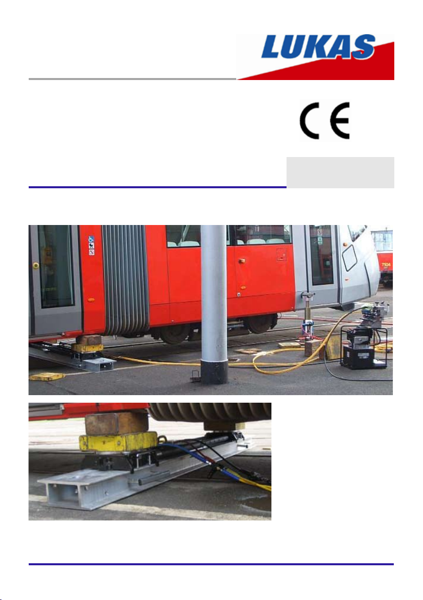
Operating instructions
Rerailing Equipment
DUO Traversing System
84072058485 GB
Edition 07.2009
replaces 12.2008
(original operating instructions)

2

3
Content Page
1. Hazard classes 4
2. Product safety 5
3. Proper use 8
4. Functions and performance 9
4.1 Description 9
4.2 Hydraulic supply of jacks 10
5. Connection of hydraulic devices 10
5.1 Basic information 10
5.2 Coupling the quick-disconnect couplings 11
6. Operation 12
6.1 Setting up the DUO traversing system 12
6.2 Start-up 25
6.3 Control of the DUO traverse jack with anchor pin 26
6.4 Control of the DUO traverse jack with anchor jack 28
7. Dismantling the equipment / deactivation after operation 30
7.1 Hydraulic jacks 30
7.2 Hose lines 30
7.3 Other components of the traversing system 30
7.4 Hydraulic supply, control and separate load listing systems 30
8. Maintenance and service 31
9. Repairs 31
9.1 General information 31
9.2 Preventative service 32
9.3 Repairs 33
10. Troubleshooting 36
11. Technical data 38
11.1 Traverse jack 38
11.2 Roller carriage 40
11.3 Rerailing bridges 40
11.4 Distance bars 41
11.5 Recommendedhydraulicuids 42
11.6 Operating and storage temperature ranges 42
12. Notes 43
4
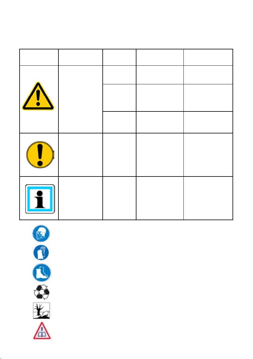
Hazard classes1.
We distinguish between various categories of safety instructions. The table below gives you
an overview of the assignment of symbols (pictograms) and key words to the specic hazard
and possible consequences.
Pictogram
Damage /
injury to
human
device
- NOTE
Key word Denition Consequences
DANGER! Immediate danger
WARNING!
CAUTION!
CAUTION!
Potentially
dangerous
situation
Less dangerous
situation
Danger of damage
to device /
environment
Advice for
application and
other important /
useful information
and advice
Death or major
injury
Potential death or
major injury
Minor or slight injury
Damage to the
equipment, damage
to the environment,
damage to
surrounding
materials
No injury / damage
to persons /
environment /
equipment
Wear helmet with face protection
Wear safety gloves
Wear safety shoes
Proper recycling
Observe principles of environmental protection
Read and observe operating instructions
5
Product safety2.
LUKAS products are developed and manufactured in order to guarantee the best performance
and quality when used properly.
Operator safety is the most important aspect of the product design. Moreover, the operating
instructions are intended to ensure LUKAS products are used safely.
The generally applicable legal and other binding regulations pertaining to the prevention of
accidents and protection of the environment apply and are to be complied with in addition to
the operating instructions.
The equipment may only be operated by persons with appropriate training in the safety
aspects of such equipment – otherwise, there is a danger of injury occurring.
We would like to point out to all users that they should read the operating instructions carefully
before using the equipment and comply with the instructions there without restriction.
We further recommend that a qualied instructor train you in the use of the product.
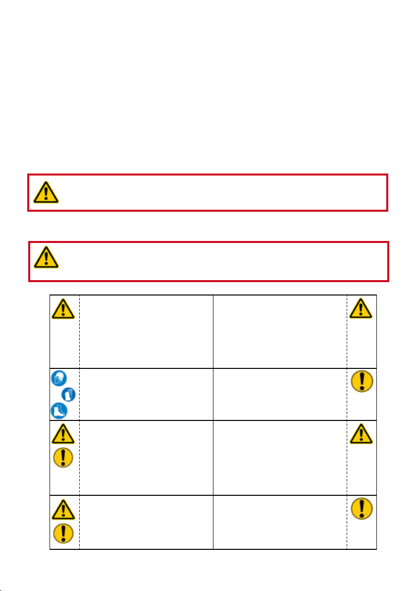
WARNING / CAUTION!
The operating instructions for the hoses, the accessories and the connected
hydraulic equipment must also be observed.
Even if you have already received instructions on how to use the equipment, you should still
read through the following safety instructions once again.
WARNING / CAUTION!
Ensure that the accessories and connected equipment used are suitable for
the maximum operating pressure.
Make sure that limbs or
clothing cannot become
trapped between the exposed
moving parts (e.g. piston
plate and jack).
Wear protective clothing,
safety helmet with visor,
safety shoes and protective
gloves
The department responsible
is to be informed immediately
of any changes (including to
the operating behaviour). If
necessary, the equipment is
to be shut down immediately
and secured.
In the event of malfunctions,
immediately shut down the
equipment and secure it. The
malfunction is to be repaired
immediately.
It is prohibited to work under
load if this load is lifted
exclusively by hydraulic
equipment. If this work
is absolutely imperative,
additional mechanical
supports must be used.
Inspect the equipment before
and after use for visible
defects or damage.
Inspect all lines, hoses and
screwed connections for
leaks and externally visible
damage. If necessary,
repair immediately. Squirting
hydraulic liquids can result in
injuries and res.
Do not carry out any changes
(additions or conversions)
to the equipment without
obtaining the prior approval of
LUKAS.
6
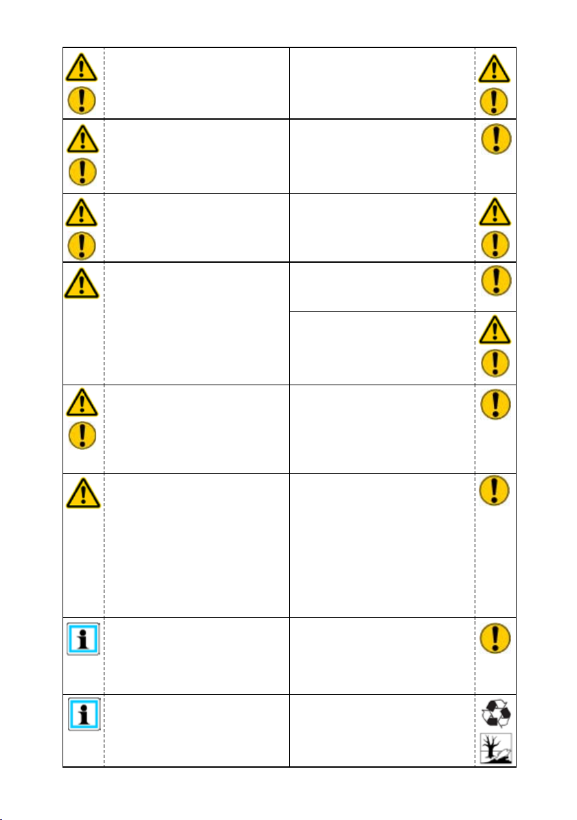
Comply with all the
instructions regarding safety
and danger on the equipment
and in the operating
instructions.
Any method of operation
which impairs safety and/or
stability of the equipment is
prohibited.
Safety devices may never be
deactivated.
All the instructions regarding
safety and danger on the
equipment are to be kept
complete and in a legible
condition.
Comply with all specied
dates or dates specied in
the operating instructions
pertaining to regular checks /
inspections of the equipment.
The maximum operating
pressure marked on the
equipment must not be
exceeded.
Before the equipment is
switched on / started up, and
during its operation, it must
be ensured that nobody is
endangered by the operation
of the equipment.
When working close to live
components and cables,
suitable measures must
be taken to avoid current
transfers or high-voltage
transfers to the equipment.
The equipment is lled with
hydraulic uid. These hydraulic
uids can be harmful to your
health if swallowed or if their
vapours inhaled. Direct contact
with the skin is to be avoided
for the same reason. Please
also note that hydraulic uids
can also have a negative effect
on biological systems.
Ensure adequate lighting when
you are working.
Always keep these operating
instructions within reach where
the equipment is used.
Only original LUKAS
accessories and spare parts
may be used for repairs.
During all work and transport
operations involving the
equipment, take care not to
trip and become caught in
hose loops.
The build-up of static
charge with the potential
consequence of spark
formation is to be avoided
when handling the equipment.
When working with or storing
the equipment, ensure that the
function and the safety of the
equipment are not impaired by
the effects of extreme external
temperatures and that the
equipment is not damaged in
any way. Please note that the
equipment can also heat up
over a long period of use.
Before transporting the
equipment, always ensure that
the accessories are positioned
in such a way that they cannot
cause an accident.
Ensure the proper disposal
of all removed parts, leftover
oil and uid, and packaging
materials.
7
The generally applicable, legal and other binding national and international regulations
pertaining to the prevention of accidents and protection of the environment apply and are to
be implemented in addition to the operating instructions.
WARNING / DANGER / CAUTION!
The equipment is to be used exclusively for the purpose stated in the operating
instructions (see chapter "Proper use"). Any form of use beyond this is not considered
proper use. The manufacturer / supplier is not liable for any damages resulting from improper
use. The user bears sole responsibility for such use.
Observance of the operating instructions and compliance with the inspection and maintenance
conditions are covered by the denition of proper use.
Never work when you are overtired or intoxicated.
8
Proper use3.
The components of the LUKAS DUO traversing unit are specially designed for rerailing
technology. In the event of derailments, the traversing unit is used to raise rail vehicles, move
them across the rails, thus allowing the vehicles to be rerailed.
A range of accessories such as base plates, stacking sets, etc. is available for specic
applications.
CAUTION!
To minimise the risk to the environment, remedy leaks as soon as possible.
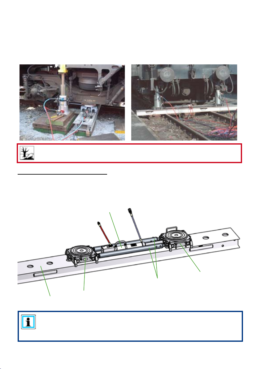
The DUO traversing unit consists of:
- Rerailing bridge (Item 1)
- Traverse jack (Item 2)
- Roller carriage (Item 3)
- Adjustable distance bars (Item 4) [optional]
2
3
4
1
NOTE:
Suitable lifting gear (e.g. LUKAS HP jack) and accessories are necessary in
order to raise rail vehicles and either move them while raised or place them on
to the DUO traversing unit.
3

9
Functions and performance4.
4.1 Description
4.1.1 Rerailing bridge
The rerailing bridge is placed across the rails and acts as the base and traverse support for
the LUKAS roller carriages and the LUKAS traverse jacks.
If one bridge is not long enough, a second bridge can be bolted on by means of connecting
elements.
The anchor pin or the integrated anchor jack of the traverse jack can be xed in the openings
at the top of the rerailing bridge. The rerailing bridges are transported by means of the pull-out
carrier handles mounted on the sides.
4.1.2 Roller carriages
The LUKAS roller carriages are designed for carrying heavy loads. The special rollers on the
underside of the roller carriage make it possible to move the carriage by hand or with the aid
of traverse jacks. The roller carriages are specically designed to match the LUKAS rerailing
bridges, thus ensuring optimum traversing of the load.
The upper sliding plate is simply placed on the roller carriage yet it can be rotated and shifted
laterally with respect to rolling direction in order to minimise the danger of a jack placed on
the plate tilting or the supported load tipping the roller carriage during operation.
4.1.3 Traverse jack
LUKAS traverse jacks are designed for the purpose of traversing the LUKAS roller carriages
on the rerailing bridges. The traverse jack is a double-acting hydraulic cylinder. The end of
the piston rod is attached to the mounting points provided in the roller carriage. This makes it
possible to move the roller carriage in the retract and extend direction of the traverse jack.
Two versions of the traverse jacks are available. The one version has a xed pin for locking
the traverse jack in the xing points of the LUKAS rerailing bridge while instead the other
version features an integrated single-acting anchor jack that performs the same function as
well as lateral guide plates.
The advantage of the version with the anchor jack is that the jack can be hydraulically adjusted
without the user having to enter the danger zone. The prerequisite for this function is that the
rerailing bridge is aligned approximately horizontal and the load is raised such that there is no
danger of the roller carriage rolling away to the side. Nevertheless, it is still essential to rmly
secure the load.
The anchor jack is always extended when in no-load position to ensure anchorage in the
rerailing bridge is always retained even in the event of pressure loss in the hydraulic system.
The anchor jack is retracted when pressure is applied, thus making it possible to shift the
traverse jack.
4.1.4 Distance bars
The distance bars are used when a load is raised at two or more points and is then to be
shifted in one direction by means of roller carriages. They are always used in pairs to connect
the roller carriages. Most distance bars feature a rough adjustment and ne adjustment
facility to allow them to be adjusted precisely to the distance between the lifting points.
Versions are also available that cannot be adjusted.
The bars are attached to the securing points in the roller carriages.
10
4.2 Hydraulic supply of jacks
Only LUKAS motor pumps or suitable LUKAS hand pumps may be used to drive the
equipment.
If an other-make pump assembly or hand pump is used, it is necessary to make sure that it
is designed in accordance with LUKAS specications otherwise hazardous situations could
occur for which LUKAS cannot be held responsible. Particular care must be taken to ensure
that the maximum permissible operating pressure of the connected LUKAS devices is not
exceeded.
NOTE:
Before you use pumps of a different manufacturer, you must contact LUKAS or
an authorised dealer.
The connection between the pump assembly or hand pump and the hydraulic jacks is made
by hose lines.
Connection of hydraulic devices5.
5.1 Basic information
Double-acting, hydraulically operated implements are tted with a male quick-disconnect
coupling on the pressure supply side (jacks: jack bottom end) and a female quick-disconnect
coupling on the return side (jacks: piston rod end); a pair of extension hoses connect them
to the control unit.
Single-acting, hydraulically operated implements are tted with a male quick-disconnect
coupling on the pressure supply side; an extension hose line connects it to the pump
assembly or control unit.
All LUKAS extension hose pairs/lines are colour-coded and equipped with quick-disconnect
couplings to minimise the possibility of misconnection.
WARNING / DANGER / CAUTION!
Before connecting equipment, make sure that all the components
used are suitable for the maximum operating pressure of the
pump unit. In cases of doubt, you must consult LUKAS directly!
11
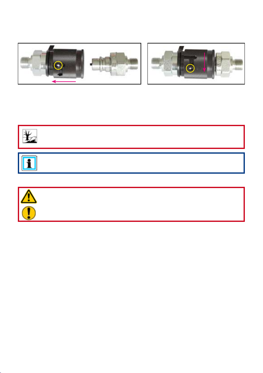
5.2 Coupling the quick-disconnect couplings
The device connects to the hydraulic pump by means of individually coded quick-connect
coupling halves (plug and socket).
X
Before coupling, remove the dust protection caps, then pull back and hold the locking sleeve
of the female coupling (position X). Connect the nipple and female coupling and let go of
the locking sleeve. To conclude, turn the locking sleeve into position Y. The connection is
now in place and secure. Uncouple in reverse order. Hoses can be connected only when
depressurised. To protect against dust, the accompanying dust protection caps must be
replaced.
CAUTION!
Always connect the return hose rst and then the supply hose.
NOTE:
Coupling of the devices is only possible when the hoses are depressurised.
To protect against dust, the accompanying dust protection caps must be replaced.
WARNING / DANGER / CAUTION!
Some quick-disconnect couplings have special functions. Therefore it is not
permitted to screw them off the hoses or to swap them.
12
Operation6.
6.1 Setting up the DUO traversing system
6.1.1 General information
The DUO traversing system consists of several individual components. By correspondingly
conguring the individual components, several different complete systems can be built up.
While not all individual components are required for some of these complete systems, you
may need several of the individual components to make up other systems.
In addition to the individual components of the DUO traversing system, you will need suitable
hydraulic jacks for lifting the load and at least one suitable hydraulic unit or hand pump to
supply the pressure.
6.1.2 Preparing to set up the traversing system
DANGER / CAUTION!
Before the individual components of the DUO traversing system can be set up,
the load to be raised must be secured in accordance with applicable guidelines
and regulations to prevent it slipping.
Check the individual components for visible damage before setting up the traversing
system.
You must pay attention to the following points while setting up the components of the
traversing system:
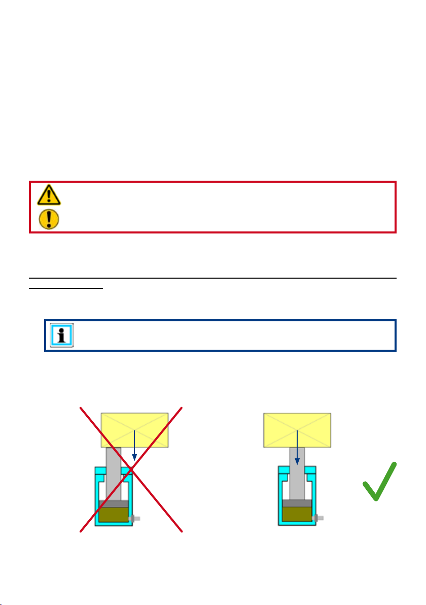
- Make sure that the load is placed centred on to the piston rod or roller carriage plate.
NOTE:
It may be necessary to select a more favourable load application point!
Position the jack/roller carriage under the centre of gravity of the load so that the load
cannot tilt during the lifting and traversing operation thus posing a danger to the operating
personnel or the equipment itself. The load must always rest centred on the surface of
the piston or roller carriage plate. Avoid off-centre loads!
Load
WRONG RIGHT
Load
13
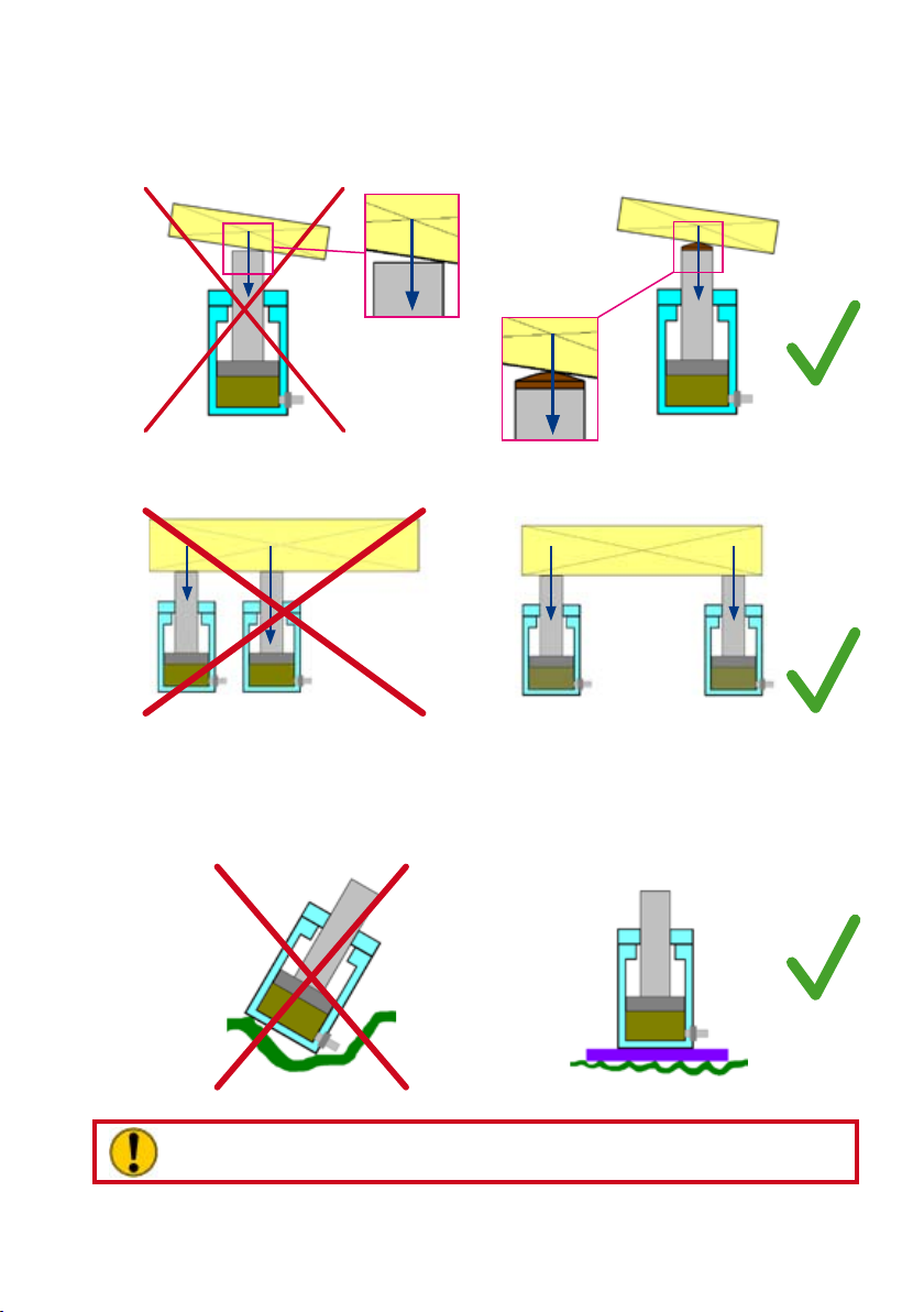
In the majority of cases it is not possible to rest the load over the entire surface of the
jack piston. We therefore recommend using suitable piston guard plates otherwise the
piston rod or jack may be damaged. A convex piston guard plate evenly distributes the
load over the surface of the piston.
Load
WRONG
If several jacks/roller carriages are used simultaneously, the load should be distributed
as evenly as possible over all jacks/roller carriages.
Load
share 1
Load share 1 < Load share 2
WRONG RIGHT
The following points must be observed while setting up jacks:
- Non-slip, at ground so that the entire base of the jack rests on the ground. If there is
doubt concerning the load bearing capability of the ground, use suitable wooden or metal
base supports in order to increase the contact area.
Load
share 2
Load
share 1
Load share 1 = Load share 2
Load
RIGHT
Load
share 2
WRONG
CAUTION!
Hydraulic uid can leave an oily lm on the ground!
- The ground must provide support over the entire area (no grids, rubble, etc.)
- Never place jacks on ductile (non-rigid) base
RIGHT
14
- To avoid damaging the piston and to ensure safe force application, never use jacks
without a piston guard plate
CAUTION!
Use an additional non-slip base between the piston guard plate and the load
to be lifted as there may also be a greasy lm at the contact point on the
load!
- Make sure that the load is applied centred on to the piston rod.
6.1.3 Setting up the rerailing bridges
The bridge is placed across the tracks and carefully supported by wooden planks. Please
ensure that:
- The rerailing bridge and the supporting wooden planks are placed on rm and
stable ground
DANGER / CAUTION!
When using wooden supports make sure that undamaged, hardwood is
used to rule out the possibility of the base splintering. It is not sufcient to
additionally strap together other pieces of wood with metal straps!
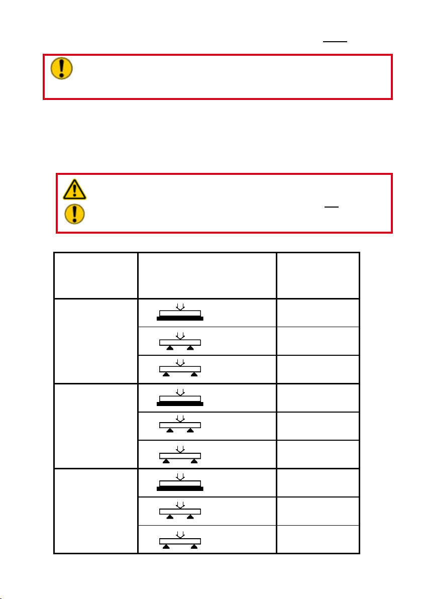
- The maximum load of the bridge is not exceeded:
Bridge height Support width Max. load
[mm] [m] [kN]
[in.] [ft.] [lb]
65 0 200
2.56 0 44,964
140 0 700
5.51 0 157,374
184 0 1200
7.24 0 269,784
* fully supported
*
*
0,5 60
1.64 13,489
1 20
3.28 4,496
*
*
1 500
3.28 112,410
1,43 400
4.69 89,928
*
*
1 900
3.28 202,338
1,43 650
4.69 146,133

15
- The maximum load of the bridge connecting elements (optional) is not
exceeded:
Bridge height Support width Max. load
[mm] [m] [kN]
[in.] [ft.] [lb]
140 1 200
5.51 3.28 44,964
184 1 300
7.24 3.28 67,446
- The bridge is horizontally aligned:
The angle of the bridge may not exceed 3°.
If one bridge is not long enough, a second bridge can be bolted on by means of connecting
elements.
For this purpose, the two rerailing bridges are placed end-to-end and bolted together with the
aid of at steel plates, bolts, washers and nuts (as shown in the picture below). Make sure
that the upper surfaces of the rerailing bridges are not axially offset otherwise trouble-free
traversing may not be guaranteed and/or the individual components may be damaged.
6.1.4 Setting up the roller carriages
The roller carriages are placed on to the rerailing bridges in such a way that the rollers of
the roller carriage are able to move along the rerailing bridges.The guides prevent the roller
carriage from slipping to the side off the rerailing bridge.

16
6.1.5 Setting up the hydraulic jacks on the roller carriage
The hydraulic jacks are placed in the centre of the upper support plate on the roller carriage
if they are to be moved together with the raised load (see illustration below).
DANGER / CAUTION!
Take care when moving a load raised by a hydraulic jack (mounted on the roller
carriage) to ensure that the load cannot tilt while traversing.
It is safer to move loads when it is raised externally by hydraulic jacks, placed on
the roller carriage then traversed.
CAUTION!
When setting up the hydraulic jacks, observe all information and instructions in
the separate operating instructions for the jacks used!
NOTE:
We recommend that you use a base plate from the LUKAS range of accessories
when you wish to move a hydraulic jack that is mounted on the roller carriage.
The base plates stabilise the jack and counteract the load tipping while
traversing.

17
6.1.6 Settingupthetraversejackswithxedanchorpin
Fit the traverse jack with the xed anchor pin in one of the matching mounting points in the
rerailing bridge and attach the piston rod head in the centre retainer on the roller carriage
(see illustration below). You may have to move the roller carriage a little in order to attach
the jack head.
NOTE:
Bear in mind that the traversing range of the jack is limited by the stroke of the
piston!
This means that the DUO traversing system must be set up such that the
stroke of the jack piston is sufcient for the required traversing range!

18
6.1.7 Setting up the traverse jack with anchor jack
Fit the traverse jack with the head of the anchor plate in one of the matching mounting
points in the rerailing bridge. For this purpose you will have to pull the slide plate on the back
end of the traverse jack up a little. Then attach the piston head of the traverse jack in the
centre retainer on the roller carriage (see illustration below). You may have to move the roller
carriage a little in order to attach the jack head.

19
Now pull up the slide plate as far as it will go and attach the guide plates on the right and left
of the traverse jack.
Slide the attached guide plates in the direction of the jack head and push the slide plate
down again.
The traverse jack is now secured on the rerailing bridge and cannot shift to the side or lift.

20
6.1.8 Setting up and adjusting the distance bars
The distance between the load lifting points must be set exactly with the distance bars. For
this reason they come with a rough and ne adjustment option.
Rough adjustment of the distance bars:
1. Pull out the lock pin.
2. The coupling bar can now be pulled out to roughly set the distance between the roller
carriages. The hole in the coupling bar must be aligned with the corresponding hole in the
tube.
3. Reinsert the lock pin in the corresponding hole in the tube.

21
Fine adjustment of the distance bars:
Fine adjustment takes place at the other end of the tube. Insert a metal rod (ø8 mm) or
similar tool in the hole in the adjusting pin and unscrew it (turn in anticlockwise direction) until
the required size is reached. For the ne adjustment, the adjusting pin can be unscrewed by
a maximum of 80 mm.
Connecting two roller carriages:
Two distance bars must always be used to connect two roller carriages. These two distance
bars must be set to the same length. They are placed in the retainers in the roller carriages
with the coupling bar on the one side and the adjusting pin on the other.

22
NOTE:
If the traverse jack is to be used between the two roller carriages, the distance
bars should be tted after setting up the traverse jack.
6.1.9 Examples of traversing systems
DANGER / CAUTION!
If there are doubts concerning the set-up of your traversing system a
correspondingly trained safety technician or LUKAS should be contacted directly
before start-up.
NOTE:
There are two methods of setting up the traverse jack in combination with two
roller carriages:
1. The traverse jack is set up between the distance bars of the roller
carriages.
2. The traverse jack is set up outside the connected roller carriages.

23
Several examples of setting up traversing systems are illustrated in the following:
1. Traversing system with one roller carriage and separate load lifting system
(recommended method)
Required components:
- Controlled hydraulic supply
(e.g. hydraulic unit with control valve)
- Separate load lifting system
(e.g. hydraulic jack with accessories)
- Rerailing bridge
- 1 roller carriage
- 1 traverse jack
- Support material (e.g. hardwood blocks)
2. Traversing system with two roller carriages and separate load lifting system
(recommended method)
Required components:
- Controlled hydraulic supply (e.g. hydraulic unit with control valve)
- Separate load lifting system (e.g. hydraulic jack with accessories)
- Rerailing bridge
- 2 roller carriages
- 1 traverse jack
- 2 distance bars
- Support material (e.g. hardwood blocks)

24
3. Traversing system with one roller carriage and mounted hydraulic jack
Required components:
- Controlled hydraulic supply
(e.g. hydraulic unit with control valve)
- Rerailing bridge
- 1 roller carriage
- 1 traverse jack
- 1 hydraulic jack
- Support material (e.g. hardwood blocks)
4. Traversing system with two roller carriages and mounted hydraulic jacks
Required components:
- Controlled hydraulic supply
(e.g. hydraulic unit with control valve)
- Rerailing bridge
- 2 roller carriages
- 1 traverse jack
- 2 hydraulic jacks
- Support material (e.g. hardwood blocks)

25
6.2 Start-up
CAUTION!
During start-up, observe all information and instructions in the separate operating
instructions for the other components of your rerailing system.
Preparations before start-up:
Before start-up, all components must be visually inspected for damage and leaks. Damaged
components must not be used and must be exchanged.
Hydraulic components must be bled before start-up takes place.
Bleeding the traverse jack:
The device must be bled before initial commissioning and after repairs:
- Connect device to hydraulic pump (see Section "Connecting the devices").
- Fully extend and retract the device several times without load.
NOTE:
We recommend that the connected hydraulic supply unit is positioned higher
than the jack during the bleeding operation.
The connections of the hydraulic jack should face upwards.
Start-up:
DANGER / CAUTION!
According to instructions, secure the vehicle to be rerailed to prevent it rolling,
slipping and tipping!
Set up all the components to be used as described under “Setting up the DUO traversing
system”. During set-up, observe all applicable standards, directives, laws and regulations.
The separate hydraulic supply and the control of the DUO traversing system must be located
outside the danger zone!
Now connect up all hydraulic components as described under “Connecting hydraulic
devices”.

26
DANGER / CAUTION!
Make sure that nobody is present in the danger zone.
The rerailing system is now ready to use!
6.3 Control of the DUO traverse jack with anchor pin
DANGER / CAUTION!
The vehicle to be rerailed must be secure according to instructions to prevent it
rolling, slipping and tipping!
NOTE:
Bear in mind that the traversing range of the jack is limited by the stroke of the
piston!
This means that the DUO traversing system must be set up such that the
stroke of the jack piston is sufcient for the required traversing range!
6.3.1 Traversing with external load lifting system (recommended method):
Procedure:
1. Set up the rerailing system as described under "Setting up the DUO traversing
system" and in the separate operating instructions of the other components used.
2. Raise the vehicle with the separate load lifting system.
3. Place suitable base material (e.g hardwood blocks or metal plates) on the roller
carriages and align such that, after lowering, the vehicle is stable and secure on the
roller carriages.
DANGER / CAUTION!
The vehicle to be rerailed must be securely raised such that it cannot slip
or tip over before placing the base material and setting up the traversing
system.
Always keep an eye on the raised vehicle when placing the base material
and setting up the system!If the vehicle begins to move in an uncontrolled
manner, leave the danger zone as fast as possible!
You must leave the danger zone after placing the base material and setting
up the system!
4. Lower the vehicle on to the roller carriages.
5. Extend the traverse jack with the separate control unit by the distance the vehicle to be
rerailed is to be traversed to the rails.
It is strictly prohibited to work under loads that are
raised solely by hydraulic means!
6. Move the separate load lifting system such that you can again safely lift the vehicle to be
rerailed. The vehicle must still remain secured to prevent it rolling, slipping and tipping!
7. Raise the vehicle to be rerailed and remove the base material from the roller
carriages.
8. Retract the traverse jack.

27
9. Lower the vehicle with the separate load lifting system.
NOTE:
If the traversing range does not extend far enough, after shifting the vehicle for
the rst time (steps 1 to 9) you will have to build up the entire traversing system
once again at the new position of the vehicle.
When rebuilding the traversing system make sure that all the prerequisites
dened under "Setting up the DUO traversing system" are met!
You can now repeat the procedure (1 to 9).
10. Finally, dismantle the components of the traversing system.
6.3.2 Traversing with hydraulic jack mounted on the roller carriage:
Procedure:
1. Set up the rerailing system as described under "Setting up the DUO traversing
system" and in the separate operating instructions of the other components used.
2. Raise the vehicle with the hydraulic jack(s) such that it (they) cannot tip over or slip
off.
DANGER / CAUTION!
The use of stacking sets or similar together with the hydraulic jack mounted
on the roller carriage is strictly prohibited!
3. Extend the traverse jack with the separate control unit by the distance the vehicle to be
rerailed is to be traversed to the rails.
NOTE:
Bear in mind that the traversing range of the jack is limited by the stroke
of the piston!
This means that the DUO traversing system must be set up such that the
stroke of the jack piston is sufcient for the required traversing range!
It is strictly prohibited to work under loads that are
raised solely by hydraulic means!
4. Lower the vehicle by retracting the hydraulic jack mounted on the roller carriage. The
vehicle must still remain secured to prevent it rolling, slipping and tipping!
5. Remove the hydraulic jack(s) from the roller carriages.
6. Retract the traverse jack.
NOTE:
If the traversing range does not extend far enough, after shifting the vehicle for
the rst time (steps 1 to 6) you will have to build up the entire traversing system
once again at the new position of the vehicle.
When rebuilding the traversing system make sure that all the prerequisites
dened under "Setting up the DUO traversing system" are met!
You can now repeat the procedure (1 to 6).

28
7. Finally, dismantle the components of the traversing system.
6.4 Control of the DUO traverse jack with anchor jack
DANGER / CAUTION!
The vehicle to be rerailed must be secure according to instructions to prevent it
rolling, slipping and tipping!
6.4.1 Traversing with external load lifting system (recommended method):
Procedure:
1. Set up the rerailing system as described under "Setting up the DUO traversing
system" and in the separate operating instructions of the other components used.
2. Raise the vehicle with the separate load lifting system.
3. Place suitable base material (e.g hardwood blocks or metal plates) on the roller
carriages and align such that, after lowering, the vehicle is stable and secure on the
roller carriages.
DANGER / CAUTION!
The vehicle to be rerailed must be securely raised such that it cannot slip or tip
over before placing the base material and setting up the traversing system.
Always keep an eye on the raised vehicle when placing the base material and
setting up the system!If the vehicle begins to move in an uncontrolled manner,
leave the danger zone as fast as possible!
You must leave the danger zone after placing the base material and setting
up the system!
4. Lower the vehicle on to the roller carriages.
5. Extend the traverse jack with the separate control unit by the distance the vehicle to
be rerailed is to be traversed to the rails.
6. Secure the load to prevent it slipping to the side.
7. If the traversing range does not extend far enough, now retract the anchor jack with
the aid of the separate control unit. (If the traversing range does extend far enough,
continue with Point 11)
8. Completely retract the traverse jack.
9. Shut down the anchor jack. The jack will consequently extend automatically.
10. Extend the traverse jack again. Due to friction, the roller carriages normally do not
move until the extended anchor jack engages in one of the retainer holes in the rerailing
bridge. Nevertheless if necessary, still secure the roller carriage to prevent it rolling
away!
Once the anchor jack has engaged, the roller carriages move in the traversing
direction of the traverse jack.

29
11. Points 9 and 10 can be repeated as often as necessary.
NOTE:
The traversing range is only limited by the length of the rerailing bridge.
DANGER / CAUTION!
When shifting several times make sure that the roller carriages are not
pushed from the rerailing bridge!
12. Move the separate load lifting system such that you can again safely lift the vehicle
to be rerailed. The vehicle must still remain secured to prevent it rolling, slipping and
tipping!
13. Raise the vehicle to be rerailed and remove the base material from the roller
carriages.
14. Lower the vehicle on to the rails with the separate load lifting system.
15. Return the traverse jack to its basic setting.
16. Finally, dismantle the components of the traversing system.
6.4.2 Traversing with hydraulic jack mounted on the roller carriage:
Procedure:
1. Set up the rerailing system as described under "Setting up the DUO traversing
system" and in the separate operating instructions of the other components used.
2. Raise the vehicle with the hydraulic jack(s) such that it (they) cannot tip over or slip
off.
DANGER / CAUTION!
The use of stacking sets or similar together with the hydraulic jack mounted
on the roller carriage is strictly prohibited!
3. Extend the traverse jack with the separate control unit by the distance the vehicle to
be rerailed is to be traversed to the rails.
4. If the traversing range does not extend far enough, now retract the anchor jack with
the aid of the separate control unit. (If the traversing range does extend far enough,
continue with Point 11)
5. Completely retract the traverse jack.
6. Shut down the anchor jack. The jack will consequently extend automatically.
7. Extend the traverse jack again. The roller carriages do not move until the extended
anchor jack engages in one of the retainer holes in the rerailing bridge. Once the anchor
jack has engaged, the roller carriages move in the traversing direction of the traverse
jack.
8. Points 6 and 7 can be repeated as often as necessary.
NOTE:
The traversing range is only limited by the length of the rerailing bridge.

30
DANGER / CAUTION!
When shifting several times make sure that the roller carriages are not
pushed from the rerailing bridge!
9. Lower the vehicle on to the rails by retracting the hydraulic jack mounted on the
roller carriage. The vehicle must still remain secured to prevent it rolling, slipping and
tipping!
10. Remove the hydraulic jack(s) from the roller carriages.
11. Retract the traverse jack.
12. Finally, dismantle the components of the traversing system.
Dismantling the equipment / deactivation following 7.
operation
WARNING / DANGER / CAUTION!
Before the rerailing equipment concerned is removed, make sure that the load is
in a stable, immovable condition.
7.1 Hydraulic jack
After completing the work, the hydraulic jacks and traverse jacks are to be retracted such
that they protrude only by a few mm*). This relieves the load in the entire system both
hydraulically and mechanically.
NOTE:
Due to uctuations in ambient temperature, slight movements can occur when
storing hydraulic jacks and traverse jacks. This effect is caused by the different
expansion rates of the hydraulic uid trapped on the piston and rod side.
*) 1 mm = 0.04 inch
7.2 Hoses
The hose lines are uncoupled as described under "Connecting the devices".
Ensure that you replace the dust protection caps onto the mono-coupling halves.
7.3 Other components of the traversing system
The components are dismantled in the reverse order they were built up.
7.4 Hydraulic supply, control and separate load listing sys-
tems
When work is completed, the hydraulic supply, control and the required load lifting systems
have to be shut down. Please refer to the separate operating instructions for these
components!

31
Maintenance and service8.
A visual inspection must be carried out after each use and at least once a year regardless
of use. In addition, a function test must be carried out every 3 years, or whenever there is
any doubt as to the safety or reliability of the equipment (observe all applicable national
and international rules and regulations relating to the maintenance intervals of the hydraulic
devices).
CAUTION!
Clean off any dirt before checking the equipment.
WARNING / DANGER / CAUTION!
In order to carry out maintenance and repair work, tools appropriate for the job
and personal protection equipment obligatory
Checks to be performed:
Visual inspection
• Jack and piston rod not damaged or deformed
• Jack accessories complete and not damaged
• Rerailing bridge not damaged or deformed
• Distance bars not damaged or deformed
• Roller carriage not damaged or deformed
• General tightness (no leaks)
• Handles present and secure
• All screw connections tightened
• Type plate, warning labels and other markings present and legible
• Couplings operate smoothly
• Dust protection caps tted
• All accessories undamaged
Function test
• Fully extend and retract piston
• Smooth extension and retraction of jacks under pressure
• Roller carriage moves smoothly without load
• Fully extend and retract distance bars
• No unusual noises
Repairs9.
9.1 General
Servicing may only be carried out by the manufacturer or personnel trained by the
manufacturer and by authorised LUKAS dealers.
Only LUKAS spare parts may be used to replace all components (see spare parts list) since
special tools, assembly instructions, safety aspects, inspections might have to complied with
(see also chapter "Maintenance and service”).
During all installation work, pay particular attention to the cleanliness of all components
as contaminants could cause damage to the equipment.
WARNING / DANGER / CAUTION!
Protective clothing must be worn when repairs are being carried out, since
parts of the units can also be pressurised in an idle state.

32
NOTE:
Before you use couplings from a different company, you must contact LUKAS or
an authorised dealer.
CAUTION!
Since LUKAS rerailing devices are designed for top performance, only those
components in the spare parts lists of the relevant unit may be replaced.
Further components in the devices may only be replaced if:
- You have participated in appropriate LUKAS service training,
- You have the explicit permission of the LUKAS customer service (on request,
check for granting permission. Check is necessary in each individual case!)
9.2 Preventative service
9.2.1 Care information
The exterior of the equipment is to be cleaned from time to time in order to protect it from
external corrosion. Oil is to be applied to the metallic surfaces.
9.2.2 Stress test
If there is any doubt regarding the safety or reliability of the equipment, a function and load
test must also be performed.
9.2.3Changingthehydraulicuidinthetraverseandanchorjack
- After approx. 200 deployments, but after three years at the latest, replace the hydraulic
uid
CAUTION!
During a hydraulic uid replacement, always use a suitable receptacle to collect
escaping uid and dispose of the collected uid correctly.
CAUTION!
All of the hydraulic uid in the system must be replaced if conditions of use
(ambient temperatures) vary considerably. When selecting the appropriate
hydraulic uid, please observe the “Recommended hydraulic uids” chapter.
Procedure:
1. Completely retract jack.
2. Unscrew hoses at the jack.
3. Drain off hydraulic uid.
4. Flush.
5. Reconnect hoses correctly.
6. Connect pump with fresh hydraulic uid and extend and retract the jack several
times.
7. Bleed jack as described under "Start-up".
8. Disconnect pump.

33
9.3 Repairs
9.3.1 Replacing couplings
The couplings must be replaced in the event of:
- external damage
- the locking device not working
- hydraulic uid continually leaking in a coupled/uncoupled state.
WARNING / DANGER / CAUTION!
Never repair couplings: they are to be replaced by original LUKAS parts.
During installation, tighten the coupling to a torque of M
= 40 Nm.
A
Procedure:
1. Remove the coupling.
2. Fit the new coupling and screw it in with a torque of M
= 40 Nm.
A
9.3.2 Replacing handles on the rerailing bridge
All damaged or broken handles must be replaced.
Procedure:
1. Pull out the damaged handle almost to the end stop.
2. Release the lock pins by pulling back the metal rings and pulling out the pins.
3. You can now pull the handle out of the rerailing bridge and replace it.
4. Assemble in reverse order of removal.
Handle
Handle
Lock pin
9.3.3 Replacing handles on the roller carriage
All damaged or broken handles must be replaced.
Procedure:
1. Undo and remove the screws holding
the handle.
2. You can now pull the handle out of the
roller carriage and replace it.
3. Assemble in reverse order of removal.
Handle
Screws

34
9.3.4 Replacing handle on the traverse jack
All damaged or broken handles must be replaced.
Procedure for handles mounted directly on the traverse jack:
1. Undo and remove the screws holding the handle together with the washers.
2. You can now detach the handle and replace it.
3. Assemble in reverse order of removal.
Screw
Screw
Washer
Washer
Handle
Procedure for handles secured with clips:
1. Undo and remove the screws and nuts.
2. You can now remove the handle and washers from the traverse jack and replace it.If
the clips are damaged, remove them by pulling them in the direction of the jack head. Be
careful not to damage the hose lines.
3. Assemble in reverse order of removal.
Handle
Washers
Screws
Clips
Nuts

35
9.3.5 Replacing sliding plate on the traverse jack with anchor jack
The sliding plate must be replaced if it is damaged, bent or broken.
Procedure:
1. Undo and remove the screws on the anchor jack.
2. You can now detach the slide plate and replace it.
3. Assemble in reverse order of removal.Make sure that the pin tted in the anchor jack
can move in the narrow slot in the slide plate.
Pin
Narrow
slot
Screws Slide plate
9.3.6 Replacing hoses on the traverse jack
All damaged or leaking hoses must be replaced.
Procedure:
1. Unscrew and remove the defective hoses from the jack together with the seals.
NOTE:
If only the hoses are defective and not the couplings, you should rst unscrew
the couplings before removing the hoses. After replacing the hose lines, the
couplings are reconnected to the new hoses (see "Replacing couplings").
2. Place the seals on the hose connections on the jack and screw on the new hoses.
(Tighten to a torque of M
= 35 Nm)
A
9.3.7 Labels
All damaged and/or illegible labels (safety signs, type plate, etc.) must be renewed.
Procedure:
1. Remove damaged and/or illegible labels.
2. Clean the surfaces using acetone or industrial alcohol.
3. Attach new labels.
Make sure that the labels are attached in the right position. If you are no longer sure about
this, contact your authorised LUKAS dealer or LUKAS directly.

36
Troubleshooting10.
Problem Check Cause Solution
Jack piston moves
slowly or erratically
during operation
Device does not build
up specied force.
hose assembly
cannot be coupled
Hydraulic uid
leaking from hoses or
connections
Damage to surface of
hydraulic hose lines
Hydraulic uid leaking
from piston rod
Leak from couplings Coupling
Hose lines
connected
correctly?
Pump assembly
running?
Hydraulic uid
level in supply
pump?
Check operating
pressure of
hydraulic
assembly
Check device Device defective Shut down device
Hose lines
defective?
damaged?
Air in hydraulic
system
Insufcient
hydraulic uid in
pump
Insufcient supply
pressure
Pressurised Switch the pump
Coupling defective Coupling needs to be
Leak, possible
damage
Mechanical
damage or contact
with aggressive
media
Piston rod seal
defective
Piston damaged
Coupling defective Coupling needs to be
Bleed pump system
Top up hydraulic uid
and bleed
If possible, increase
the max. operating
pressure at the
hydraulic unit to
the max. operating
pressure of the
cylinder or use a
different hydraulic
unit with sufcient
max. operating
pressure.
and repair (have
repaired)
to depressurised
circulation
replaced immediately
Replace hoses
Replace hoses
Have problem
rectied by
authorised dealer,
personnel trained by
LUKAS or LUKAS
directly
replaced immediately

37
If it is not possible to rectify the malfunctions, inform an authorised LUKAS dealer or the
LUKAS Customer Service department immediately.
The address for the LUKAS Customer Service department is:
LUKAS
Weinstraße 39, D-91058 Erlangen
Postfach 2560, D-91013 Erlangen
Tel.: (+49) 09131 / 698 - 348
Fax.: (+49) 09131 / 698 - 353
Hydraulik GmbH

38
Technical data11.
As all the values are subject to tolerances, there can be minor differences between the data
of your devices and the data in the following tables!
11.1 Traverse jack
Device type TC170/90-350
Article number 84072/0564
Dimensions
(W x H)
Length
(retracted)
Length
(extended)
Max. stroke
Pressure
Tractive force
Weight including
hydraulicuidll
Max. operating
pressure
Operatinguid
quantity
Special feature Anchor jack
[mm] 363 x 186
[in.] 14.29 x 7.32
[mm] 668
[in.] 26.30
[mm] 989
[in.] 38.94
[mm] 321
[in.] 12.64
[kN] 176
[lbf.] 39,568
[kN] 92
[lbf.] 20,683
[kg] 22,5
[lb] 49.6
[MPa] * 53
[psi] 7,687
[l]** 0.509
[gal.-US] 0.134
* 1 MPa = 10 bar
** The amount of hydraulic uid in the hydraulic assembly necessary to operate the
device (differential quantity: piston/rod side)

39
Device type TC330/200-350
Article number 84072/0569 84072/0584
Dimensions
(W x H)
Length
(retracted)
Length
(extended)
Max. stroke
Pressure
Tractive force
Weight including
hydraulicuidll
Max. operating
pressure
Operatinguid
quantity
Special feature Anchor jack No anchor jack
[mm] 370 x 213 90 x 176
[in.] 14.57 x 8.39 3.54 x 6.93
[mm] 685 653
[in.] 26.97 25.71
[mm] 1007 974
[in.] 39.65 38.35
[mm] 322 321
[in.] 12.68 12.64
[kN] 337 176
[lbf.] 75,764 39,568
[kN] 207 92
[lbf.] 46,538 20,683
[kg] 43 20
[lb] 94.8 44.1
[MPa] * 53
[psi] 7,687
[l]** 0,793 0.509
[gal.-US] 0.209 0.134
TC170/90-350
SBB
* 1 MPa = 10 bar
** The amount of hydraulic uid in the hydraulic assembly necessary to operate the
device (differential quantity: piston/rod side)

40
11.2 Roller carriages
Device type RC-700/350 RC-1000/350
Article number 840720640 840721631
Dimensions
(L x W x H)
Max. width of
rerailing bridge
Max. permissible
load
Mass
[mm] 390 x 380 x 130 360 x 380 x 140
[in.] 15.35 x 14.96 x 5.12 14.17 x 14.96 x 5.51
[mm] 350 350
[in.] 13.78 13.78
[kN] 750 1000
[lbf.] 168,615 224,820
[kg] 41,6 63
[lb] 91.7 138.9
11.3 Rerailing bridges
Device type 1.1 m / 65 mm 2.2 m / 65 mm 3.3 m / 65 mm
Article number 840726340 840725760 840725040
Dimensions
(L x W x H)
Mass
Device type 1.1 m / 140 mm 2.2 m / 140 mm
Article number 840726350 840725750
Dimensions
(L x W x H)
Mass
[mm] 1100 x 350 x 65 2200 x 350 x 65 3300 x 350 x 65
[in.] 43.31 x 13.78 x 2.56 86.61 x 13.78 x 2.56 129.92 x 13.78 x 2.56
[kg] 20 39 59
[lb] 44.1 86.0 130.1
[mm] 1100 x 350 x 140 2200 x 350 x 140
[in.] 43.31 x 13.78 x 5.51 86.61 x 13.78 x 5.51
[kg] 40 81,5
[lb] 88.2 179.7
Device type 3.3 m / 140 mm 4.4 m / 140 mm
Article number 840725050 840726550
Dimensions
(L x W x H)
Mass
[mm] 3300 x 350 x 140 4400 x 350 x 140
[in.] 129.92 x 13.78 x 5.51 173.23 x 13.78 x 55.1
[kg] 120,5 163
[lb] 265.7 359.3

41
Device type 1.1 m / 184 mm 2.2 m / 184 mm
Article number 840726381 840726382
Dimensions
(L x W x H)
Mass
Device type 3.3 m / 184 mm 4.4 m / 184 mm
Article number 840726383 840726384
Dimensions
(L x W x H)
Mass
[mm] 1100 x 350 x 184 2200 x 350 x 184
[in.] 43.31 x 13.78 x 7.24 86.61 x 13.78 x 7.24
[kg] 70 140
[lb] 154.3 308.6
[mm] 3300 x 350 x 184 4400 x 350 x 184
[in.] 129.92 x 13.78 x 7.24 17.32 x 13.78 x 7.24
[kg] 210 280
[lb] 463.0 617.3
11.4 Distance bars
Device type 1830/1030 2800/1500 1094 1695 2384
Article number 840720580 840720582 840720591 840720592 840720593
Length
(retracted)
Length
(extended)
Dimensions
(diameter)
Mass
[mm] 1030 1500 1094 1695 2384
[in.] 40.55 59.06 43.07 66.73 93.86
[mm] 1830 2800 - - -
[in.] 72.05 110.24 - - -
[mm] 50 50 65 65 65
[in.] 1.97 1.97 2.56 2.56 2.56
[kg] 40 65 25,4 37,4 51,2
[lb] 88.2 143.3 56.0 82.4 112.9

42
11.5 Recommendedhydraulicuids
Mineral oil DIN ISO 6743-4 for LUKAS hydraulic equipment and others
Oil temperature range Oil code Viscosity rating Remarks
A -24 .... +30°C HL 5 VG 5
B -18 .... +50°C HM 10 VG 10
C -8 .... +75°C HM 22 VG 22
D +5 .... +80°C HM 32 VG 32
E -8 .... +70°C HF-E15 VG 15 Bio-oil
Oil temperature range Oil code Viscosity rating Remarks
A -11.2 .... +86°F HL 5 VG 5
B -0.4 .... +122°F HM 10 VG 10
C +17.6 .... +167°F HM 22 VG 22
D +41.0 .... +176°F HM 32 VG 32
E +17.6 .... +158°F HF-E15 VG 15 Bio-oil
recommended viscosity range: 10...200 mm²/s (10…200 cSt.)
Supplied with HM 22 DIN ISO 6743-4.
11.6 Operating and storage temperature ranges
Operating temperature [°C] -20 … +55
Ambient temperature (device in operation) [°C] -25 … +45
Storage temperature (device not in operation) [°C] -30 … +60
Operating temperature [°F] -4 … +131
Ambient temperature (device in operation) [°F] -13 … +113
Storage temperature (device not in operation) [°F] -22 … +140

43
Notes12.

Please dispose all packaging materials and
dismantled parts properly.
LUKAS
Weinstraße 39, D-91058 Erlangen
Postfach 2560, D-91013 Erlangen
Tel.: (+49) 0 91 31 / 698 - 0
Fax.: (+49) 0 91 31 / 698 - 394
e-mail: lukas.info@idexcorp.com
Hydraulik GmbH
Made in GERMANY
© Copyright 2010 LUKAS Hydraulik GmbHDUO_Verschiebesystem_BA_GB_84072058485_0709.indd
Subject to revision
 Loading...