

Page 1
Operating Instructions
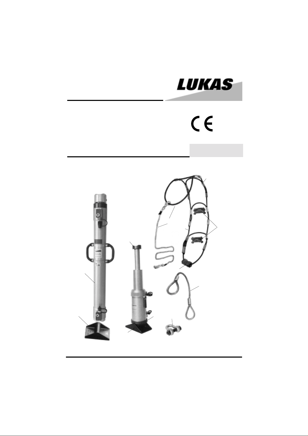
Rerailing Equipment
Double-acting
Rope-lift cylinder
(3.3)
1
(4.1)
(4.2)
84072/5355-85 GB
Issue 2.2005
4
5
3
(4.3)
3
2
(3.2)
(3.1)
1
6
1 Rope-lift cylinder
2 Radius plate
3 Tilting set
4 Lifting belt
5 Holding rope
6 Shackle
Page 2

Contents page
1 Safety instructions 3
2 Organisational measures 3
3 General safety instructions 4
4 Instructions for maintenance and service 5
5 Function of components 5
5.1 General
5.2 Connecting pieces
5.3 Hoses between the control table and cylinders
5.4 Quick-connect couplings
5.4.1 Hose pair compliant with 84072/1765
5.4.2 Connection of quick-connect couplings
6 Initial commissioning 7
7 Installation 7
7.1 Safety notes
7.1.2 General information for cylinder installation / operation
7.1.3 Note for cylinder retraction
8 Hydraulic connection and operation 7
8.1 General
8.1.1 Connection of the rope-lift cylinder
8.2 Cylinder operation
8.3 Uprighting of rolling stock
9 Accessories 8
9.1 Radius plates
9.2 Tilting set
9.3 Lifting belt
9.4 Holding rope
9.5 Shackle
10 Dismantling of components 9
11 Maintenance 9
11.1 Mechanical inspection
11.2 Hydraulic system leakage
11.3 Cylinder components
11.4 Oil recommendation
12 Malfunctions / trouble-shooting 10
13 Repair 11
14 Circuit diagram 11
15 Technical data 12
2
Page 3

1 Safety instructions
Designated use of the device
1.1 The cylinders described below may only be used together with LUKAS rerailing equipment
components. It is possible to use the device with equipment made by other manufacturers, however
LUKAS must carry out the technical check and grant approval in each individual case.
1.2 The designated use of the device is exclusively the power supply and control of rerailing
equipment. Any other or additional use, such as the power supply and control of other hydraulic
systems is deemed to be contrary to the designated use. The manufacturer/supplier cannot be
held liable for any damage resulting from such use. The risk of such misuse lies entirely with the
user.
Designated use also includes conforming to the Operating Instructions as well as compliance with
the inspection and maintenance directives (refer to Chapter 4 and Chapter 13).
1.3 The device has been constructed in accordance with the state of the art and the recognised
safety rules. Nevertheless, its use may constitute a risk to life and limb of the user or of third parties,
or result in damage to the device and to other material property.
1.4 Only use the device when it is in a technically perfect condition, as well as in accordance with
designated use, in awareness of safety and hazards and in compliance with the Operating
Instructions. Any malfunctions, especially those which could affect the safety of the device, should
therefore be rectified immediately.
1.5 Device designation
HP 25 / 800 R
Total stroke
in mm
Hydraulic
retraction
High-pressure
cylinder
Rated
compression
force
in metric tons
2 Organisational measures
2.1 Always keep the Operating Instructions ready to hand at the location where the device is
used.
2.2 In addition to the requirements contained in the Operating Instructions, comply with and
provide instruction in the general legal provisions and other mandatory regulations that apply to
accident prevention and environmental protection.
This includes in particular the wearing of working or protective clothing, a helmet with visor or
goggles and protective gloves.
2.3 The device may only be operated by persons who have received appropriate safety training,
otherwise there is a risk of injury. Particular attention must also be to paid to the influence of stress
factors upon operators when the device is being used. These factors may cause a risk to life and
limb of users or of third parties, or result in damage to the device and to other material property.
2.4 Comply with all safety instructions and hazard warnings on the device. Make sure that safety
instructions and hazard warnings displayed on the device are always complete and perfectly
legible.
2.5 Obtain approval from the supplier before making any modifications, additions or conversions
to the device that may reduce safety. This also applies to the installation and adjustment of safety
devices and valves.
3
Page 4

2.6 Spare parts must conform to the technical requirements specified by the manufacturer.
This is always guaranteed for spare parts supplied by original equipment manufacturers. In
the same way, only original LUKAS spare parts or LUKAS system components may be
used.
2.7 Replace hydraulic hoses at the stipulated or suitable time intervals even if safety-relevant
defects cannot be detected. This must be done after 10 years at the latest.
2.8 Comply with the prescribed intervals or those specified in the Operating Instructions for
periodic checks/inspections.
2.9 Make sure that all packaging materials and removed parts are disposed of correctly.
3 General safety instructions
3.1 Check all parts for damage prior to commissioning.
3.2 Take the environmental conditions into account when using the device and adapt your
personal protective clothing to them. Also, do not forget that the cylinders may heat up over
time. The environmental conditions may also cool them down considerably. Provision must also
be made for these conditions by wearing suitable protective clothing.
3.3 Also note that noise from different sources may cause adverse effects and impede
communication during operation.
Adverse effects during operation are also possible from exhaust fumes. Make sure that there is
sufficient ventilation or that appropriate protective measures have been taken.
The cylinders are connected by hoses that may also present a hazard of stumbling. Make sure that
hoses are routed safely. Take particular account of the fact that escape routes should be provided.
3.4 Make sure that lighting is adequate during working, and that a clear view is provided of the
device so that work is carried out free of danger.
3.5 Make sure that persons cannot be placed in danger from the running device prior to switching
it on, starting it up and during its operation. Also, secure the device against being switched on or
off without authorisation or accidentally.
3.6 Stop and secure the device immediately if there are any malfunctions. Have any defects
rectified immediately.
3.7 Always check that the accessories have been safely stowed away prior to transporting
the device. Bear the weight of the LUKAS rope-lift cylinders in mind during transportation.
3.8 Do not carry out any operation that degrades the device’s stability. Therefore, always use
a base plate (refer to Chapter 9.1). Also, make sure that the ground has sufficient load-bearing
capacity.
3.9 After each use, check the device for any external damage and defects. Report any chan-
ges (incl. changes in the device’s working behaviour) to the relevant organisation/person
immediately. If necessary, stop the device immediately and lock it. Check all lines, hoses and
screwed connections for leaks and externally visible damage. Rectify any damage immediately.
Splashing oil may cause injury and fires.
4
Page 5

3.10 Check all safety equipment for completeness and perfect condition:
- Instruction markings and warning signs (safety instructions)
- Check that safety covers (e.g. motor safety covers, heat shields etc.) are fitted and that
they are in good condition.
3.11 It is not permitted to work under loads if they are raised solely by hydraulic cylinders. If
such work is unavoidable, then additional mechanical supports are required.
3.12 Do not place hoses under mechanical strain (pulling, bending etc.).
3.13 Precautions must be taken to prevent conductive connections or high-voltage flashovers
to the motor pump when work is carried out in the vicinity of voltage-carrying components and
cables.
3.14 The creation of electrostatic charges that may cause spark formation must be prevented
when working with the device.
3.15 During installation of the cylinders, make sure that intense external temperatures are unable
to impair the device operation and safety.
4 Instructions for maintenance and service
4.1 T ools and workshop equipment appropriate to the job at hand are essential for carrying out
maintenance and service tasks. Work on the device may be carried out only by personnel possessing special knowledge and experience with hydraulic equipment.
4.2 Clean oil and all dirt from the device paying special attention to connectors and screwed
connections prior to starting the work. Never use aggressive cleaning agents. Use lint-free cleaning cloths and observe meticulous cleanliness in particular during reassembly.
4.3 When devices are disassembled, make sure that all escaping hydraulic oil is collected,
does not get into the ground and is disposed of in compliance with existing regulations.
4.4 Always tighten loosened screws and screw joints up to the prescribed torques.
4.5 Aggressive media (acids, lyes, solvents, vapours) may damage the device. The whole
device must be cleaned thoroughly if, exceptionally, it had to be operated in such an environment or came into contact with such media. Additionally, the device must be checked as described under 3.9.
Please also comply with our separate “Safety Instructions for Hydraulic Hoses” 84150/
8056-85 (delivered with the hoses).
5 Function of components
5.1 General
LUKAS rope-lift cylinders are manufactured from a high-alloy light metal.
They are designed for an operating pressure of 530 bar.
5
Page 6

5.2 Connecting pieces
In addition to the quick-connect couplings, these cylinder models are fitted with two connecting
blocks with a safety valve to prevent damage to the cylinder under external load. If the specified
maximum pressure is exceed, the safety valves automatically open and oil (protected) is squirted
out.
5.3 Hoses between the control table and cylinders
Connection is normally made with 10 m hose pairs red/blue (order no. 84072/1765). All hoses are
fitted with quick-connect couplings and colour coded to prevent them being connected incorrectly:
- Connection to A (= “extend”) red
- Connection to R (= “retract”) blue
5.4 Quick-connect couplings
5.4.1 Hose pair compliant with 84072/1765
The hose connectors of this hose pair are fitted with a “quick-stop function” as standard that, for
instance, blocks oil backflow out of the cylinder and prevents the load from lowering if a hose breaks.
The quick stop may be triggered unintentionally when a very heavy load is lowered or the switch
control valve is switched to “Senken” (lowering) too quickly. It will then no longer be possible to
retract the cylinder. If this happens, switch the switch control valve to “Heben” (lifting) until the
cylinder starts to extend. Carefully start the lowering procedure again.
5.4.2 Connection of quick-connect couplings
- Remove dust protection covers.
- Unlock connect socket with adjusting ring by turning it.
- Retract sleeve and connect plug and socket while holding the sleeve in this position.
- Release sleeve and lock adjusting ring: showglass is “RED”.
The connection has now been made and secured.
Note regarding the modified release mechanism as of June 2004
Whenever a connection is made, note the basic functions of the quick-connect couplings
described below:
X
Prior to making the connection, pull back and hold the plug locking sleeve in position (position X).
Fit the socket and plug together and release the locking sleeve. Then turn the locking sleeve to
position Y.
The connection has now been made and locked. Disconnection is made in the reverse order.
It is only possible to connect devices when the hoses are depressurised.
The provided dust protection caps are used to protect against dust.
6
Y
Page 7

Important!
Some quick couplers have special functions and therefore must not be unscrewed from the hoses
and/or interchanged.
To avoid dirt from entering when the couplings are disconnected, fit dust protection caps on the plug
and socket or, if the couplings are connected, fit the dust protection caps together.
6 Initial commissioning
The cylinders must be vented prior to being used for the first time.
- Extend the pistons approximately halfway when they are free from any load.
- Turn the cylinders upside down; the cylinder’s highest point must be under the motor pump
connections.
- Extend the pistons two or three times by using the appropriate switch control valve so that
air can escape from the cylinders and hoses.
7 Installation
7.1 Safety notes
7.1.1 Prior to installing the cylinder, the load to be lifted must be secured against slipping as
prescribed in the respective applicable guidelines. Always observe the load while it is being
moved by means of the cylinder!
It is forbidden for persons to be under suspended loads. If this is unavoidable in exceptional
situations, then these loads must be adequately mechanically secured so that they cannot shift
in any direction.
7.1.2 General information for cylinder installation / operation
- The ground must be non-slip and level, (warning: hydraulic oils may produce a lubricating
film on the floor.)
- The ground must be a continuous surface (no gratings, gravel etc.)
- Never place cylinders on a yielding support
- Never use cylinders without a piston guard plate in order to prevent piston damage; and
always use a LUKAS radius plate to ensure that force is transmitted safely (refer to
Accessories, Chapter 9).
- Make sure there is centred load initiation on the pistons. If necessary, look for a better
load application point.
7.1.3 Note for cylinder retraction
The load may only be lowered when the pump is running, otherwise a vacuum would be caused
when the load retracts and air would then enter into the hydraulic system.
8 Hydraulic connection and operation
8.1 General
Only connect the cylinders after installation has been carried out correctly in accordance with
Chapter 7. Switch off the motor pump before connecting hydraulic hoses.
8.1.1 Connection of the rope-lift cylinder
As described in Section 5.3, connect the blues hose first, then the red hose of the hose pair.
7
Page 8

8.2 Cylinder operation
This must be carried out in accordance with the operating instructions of the motor pump used.
8.3 Uprighting of rolling stock
With the uprighting system, overturned rolling stock can be turned back to its normal position so
that it may be rerailed.
The lifting belt (4) is fastened to the vehicle framed by means of a holding rope (5) and shackle (6).
The plastic rope is now thrown over the vehicle, and the lifting belt is pulled tight and fastened to
the frame or another superstructural part.
The rope-lift cylinder (1) or tilting jack (3) is used to raise the vehicle at the lifting belt crossbars.
When the cylinder is completely extended, a second rope-lift cylinder or tilting jack is placed in
position for further uprighting.
Each extension cycle must be secured mechanically (beam support).
9 Accessories
9.1 Radius plates (2)
Radius plates are provided to:
- Increase the base area of the cylinders,
- Increase static stability,
- Level out unevenness of the ground.
8
Page 9

9.2 Tilting set (3) comprising:
- Swivel base (3.1)
- Radius plate (3.2)
- Piston guard plate (3.3)
Telescopic cylinder HP 25 / T 450 R (has to be ordered separately)
9.3 Lifting belt (4) comprising:
- Lifting belt with plastic rope (4.1)
- Rope roller (4.2)
- Pressure piece (4.3)
9.4 Holding rope (5)
9.5 Shackle (6)
10 Dismantling of components
Dismantle the components in the reverse order of the installation sequence. Before final
dismantling of equipment, it must be ensured that:
——> The load is in a stable, immovable position <——
——> The hydraulic power pack drive motor must be shut down <——
——> All hoses must be depressurised, by: <——
- Briefly moving the switch control valves to "SENKEN" (lowering) (pressure discharge from
the hoses) and back to the centre position.
- Disconnect the DEPRESSURISED hoses in this order:
——> Hose, piston side red
——> Hose, rod side blue
11 Maintenance
11.1 Mechanical inspection
Components must be checked to establish that they operate perfectly after each usage
(clean beforehand if dirty):
- Each piston must be checked for smooth retraction (cylinder/ piston O.K.?).
- Check whether all hydraulic screwed connections on cylinders and hoses are still tight; tighten
them if necessary.
- Check whether mechanical damage is evident on the mechanical parts and hoses of cylinders.
- Check on all signs: whether warnings, operation and control symbols and other markings
(colour codings) are present and legible.
- Check whether all safety equipment (protective guards etc.) is present and in perfect condition.
- Check whether the accessories (radius plates, header plates, etc.) are in perfect condition.
9
Page 10

11.2 Hydraulic system leakage
- Check equipment for oil loss and replace any defective seals.
Important:
Carry out the following procedures over an oilpan; dispose of used oil in accordance with
regulations.
11.3 Cylinder components
Remove any oil remaining in the piston chamber and piston ring zone by fully unscrewing the two
quick-connect couplings from the connecting blocks of all lifting cylinders and carefully draining the
oil.
Flush and fill up with new hydraulic oil. Screw in the couplings tightly and tighten to a torque of
MA=45 Nm Vent cylinders in accordance with Chapter 6.
Note:
Please note that the filled oil must be fully drained and replaced by another type if the operating
conditions (ambient temperatures) change significantly. Also refer to the chapter below.
11.4 Oil recommendation
Oil for LUKAS hydraulic devices: mineral oil in accordance with DIN 51524 and others
Oil temperature range Viscosity rating Comments
A - 24 ... + 30 °C HL 5
B - 18 ... + 50 °C HLP 10
C - 8 ... + 75 °C HLP 22
D + 5 ... + 80 °C HLP 32
E - 8 ... + 70 °C HF - E 15 Biodegradable oil
Recommended range of viscosity: 10 ... 200 (mm2/s).
12 Problems / trouble-shooting
Index: P = Problem S = Symptom
P: Rope-lift cylinder pistons do not retract
S: Red hose to the cylinder piston side is pressurised.
——> Quick-stop function on the lifting cylinder is effective; clear by briefly pressing "HEBEN"
(lifting) and slowly opening the corresponding switch control valve for "SENKEN" (lowering)
P: Hoses on the cylinder cannot be connected
S: Red hose to the piston side is pressurised
——> Hoses were incorrectly disconnected when pressurised.
- Slacken the union nut on the hose fitting; cover the fitting against oil spray.
- Hose becomes depressurised; pay attention to oil spray.
- Retighten the union nut (MA = 35 Nm).
Contact an authorised LUKAS dealer or the LUKAS Customer Service Department directly if the
malfunctions cannot be rectified. The address of the LUKAS Customer Service Department is:
LUKAS Hydraulik GmbH, Weinstraße 39, D-91058 Erlangen; PF 2560, D-91013 Erlangen;
Service tel.: +49 9131-698348; Fax +49 9131-698353.
10
Page 11

13 Repair
Only original LUKAS spare parts as listed in the spare parts list may be used for renewal of all
LUKAS rerailing equipment components as it is important that any appropriate special tools,
assembly notes, safety aspects and checks must be used and applied. Refer to Section 2.6 and
Chapter 4 of these Operating Instructions.
14 Circuit diagram
11
Page 12

15 Technical data
HP 25 / 800 R
Order no. 84072/5355N
Permissible pressure 53 MPa (530 bar)
Length, extended 1893 mm
Total stroke 800 mm
Lifting force 266 kN
Oil requirement 3.1 l
Ambient temperature -20 ... +55 °C
Dimensions dia. x height Dia. 115 x 1093 mm
Weight 23.5 kg
LUKAS Hydraulik GmbH
A Unit of IDEX Corporation
Weinstraße 39, 91058 Erlangen • Germany
Postfach 2560, 91013 Erlangen • Germany
Telefon: +49(0)9131/698-0 • Telefax: +49(0)9131/698-394
e-mail: info@lukas.de
84072_5355_85_205_e.p65 Subject to revision
12
© Copyright 2005 LUKAS Hydraulik GmbH
 Loading...