

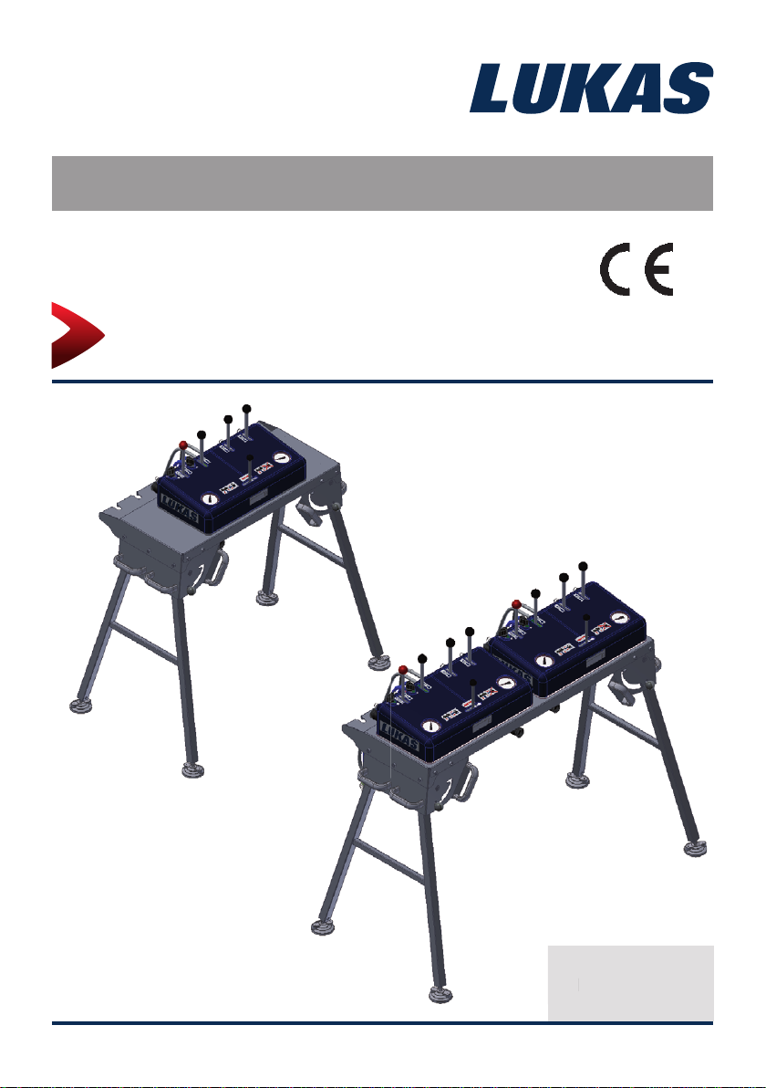
Instruction Manual Rerailing Equipment
90000085 EN
Control tables CU 2DV and CU 4DVV
CU 2DV
CU 4DVV
(Translation of the original instruction manual)
1490000085 EN
14
Edition 09.2014
Edition 09.2014

2

Content Page
1. Danger classifi cations 4
2. Product safety 5
3. Proper use 8
4. Components and functions 9
4.1 Description 9
4.2 Hydraulic supply 9
4.3 Installation of the control table 10
4.4 Functions and controls available at the control desk 11
5. Erection and start-up 13
5.1 Folding out the support frame 14
5.2 Connection of the working equipment 15
5.3 Coupling the quick-disconnect couplings 15
6. Dismantling the equipment / deactivation following operation 16
7. Maintenance and service 17
7.1 General information 17
7.2 Repairs 18
8. Troubleshooting 19
9. Technical data 21
9.1 Control unit CU 2DV 21
9.2 Control unit CU 4 DVV 22
9.3 Operating and storage temperature ranges 22
10. EC Declaration of Conformity 23
11. Notes 24
3
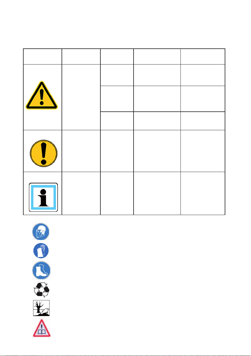
1. Danger classifi cations
We differentiate between various different categories of safety instructions. The table shown
below provides an overview of the assignment of symbols (pictograms) and signal words to
the specifi c danger and the possible consequences.
Pictogram
Damage /
injury to
Persons
Property
- NOTE
Key word Defi nition Consequences
DANGER! Immediate danger
WARNING!
CAUTION!
ATTENTION!
Potentially
dangerous
situation
Less dangerous
situation
Danger of damage
to property/
environment
Handling tips and
other important/
useful information
and advice
Death or severe
injury
Potential death or
serious injury
Minor or slight
injury
Damage to the
equipment,
damage to the
environment,
damage to
surroundings
No injury/damage
to persons/
environment/
device
Wear a helmet with a face guard
Wear protective gloves
Wear safety shoes
Proper recycling
Protect the environment
Read and follow the operating instructions
4
2. Product safety
LUKAS products are developed and manufactured to ensure the best performance and
quality when used as intended.
The safety of the operator is the most important consideration in product design. Furthermore,
the operating instructions are intended to help in using LUKAS products safely.
The generally applicable legal and other binding regulations pertaining to the prevention of
accidents and protection of the environment apply and are to be complied with in addition to
the operating instructions.
The equipment must only be operated by persons with appropriate training in the safety
aspects of such equipment – otherwise, there is a danger of injury.
We would like to point out to all users that they should read carefully the operating instructions
and the instructions contained therein before they use the equipment, and that they should
carefully follow such.
We also recommend that you have a qualifi ed trainer show you how to use the product.
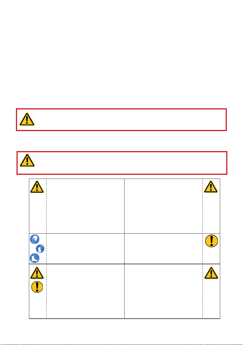
WARNING / CAUTION!
You must also observe the operating instructions for the hoses, the
accessories and the connected devices!
Even if you have already received instruction on how to use the equipment, you should still
read through the following safety instructions again.
WARNING / CAUTION!
Ensure that the accessories and connected equipment are suitable for the
maximum operating pressure!
Please ensure that no body
parts or clothing get stuck
between the visibly moving
parts.
Wear protective clothing,
a safety helmet with visor,
protective footwear and gloves
Immediately report any
changes that occur (including
changes in operating
behaviour) to the appropriate
persons/departments! If
necessary, the equipment is to
be shut down immediately and
secured!
Working under suspended
loads is not permitted where
such loads are being lifted
only using hydraulic devices.
If working under suspended
loads is unavoidable, suitable
mechanical props are also
required.
Inspect the device before and
after use for visible defects or
damage.
Check all lines, hoses and
screwed connections for leaks
and externally visible damage,
and repair immediately!
Escaping hydraulic fl uid can
cause injuries and fi res.
5
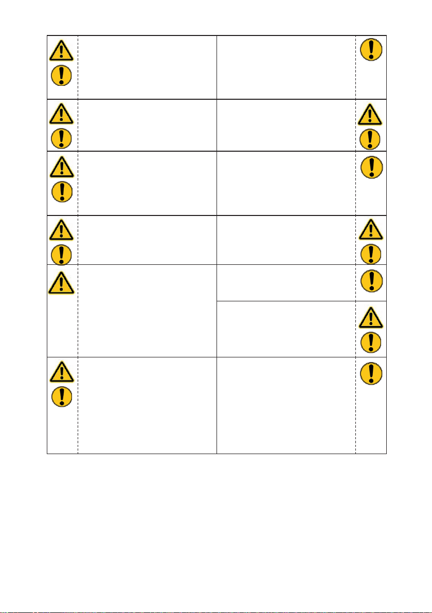
In the event of malfunctions,
immediately deactivate the
equipment and secure it.
Repair the fault immediately.
Do not carry out any changes
(additions or conversions)
to the equipment without
obtaining the approval of
LUKAS beforehand.
Observe all safety and danger
information on the device and
in the operating instructions.
Any mode of operation which
compromises the safety and/
or stability of the device is
forbidden!
Safety devices must never be
disabled!
Make sure before switching
on/starting up the device and
during its operation, that this
will put no one in danger.
When working close to live
components and cables,
suitable measures must be
taken to avoid current transfers
or high-voltage transfers to the
equipment.
All safety and danger
instructions on the device must
always be complete and in a
legible condition
Observe all intervals for
recurring tests and/or
inspections that are prescribed
or stated in the operating
instructions.
The maximum permitted
operating pressure noted on
the equipment must not be
exceeded.
Only genuine LUKAS
accessories and spare parts
are to be used for repairs.
Please ensure that, when
working with this equipment or
during transportation of such,
you don’t get caught up in the
looped hoses and trip.
The build-up of static charge
and therefore possible
sparking must be avoided
when handling the device.
6
The equipment is fi lled with
hydraulic fl uid. This hydraulic
fl uid can be detrimental to
health if it is swallowed or
its vapour is inhaled. Direct
contact with the skin must be
avoided for the same reason.
Also, when handling hydraulic
fl uid, note that it can negatively
affect biological systems.
When working with or storing
the equipment, ensure that the
function and the safety of the
equipment are not impaired
by the effects of severe
external temperatures or that
the equipment is damaged in
any way. Please note that the
equipment can also heat up
over a long period of use.
Make sure there is adequate
lighting while working.
Always keep these operating
instructions easily accessible
at the place of operation.
In addition to the safety instructions in this operating manual, all generally applicable,
statutory and otherwise binding national and international regulations for accident prevention
must be heeded and disseminated!
Before transporting the
equipment, always ensure that
the accessories are positioned
in such a way that they cannot
cause an accident.
Dispose properly of all
disassembled parts, oil and
left-over fl uid, as well as
packaging materials.
WARNING / CAUTION / ATTENTION!
The device is intended exclusively for the purpose stated in the operating instructions
(see chapter "Proper Use"). Any other use is not considered to be as intended. The
manufacturer/supplier is not liable for any damage resulting from use not as intended. The
user bears sole responsibility for such use.
Proper use includes observance of the operating instructions and compliance with the
inspection and maintenance conditions.
Never work in a fatigued or intoxicated state!
WARNING / CAUTION / ATTENTION!
However, if you do injure yourself on the hydraulic unit, clean the wound
immediately and consult a doctor to have it attended to!
If you get hydraulic fl uid in your eye, rinse it immediately several times with clear,
clean water and consult a doctor!
Also, if you swallow hydraulic fl uid you should consult a doctor!
7
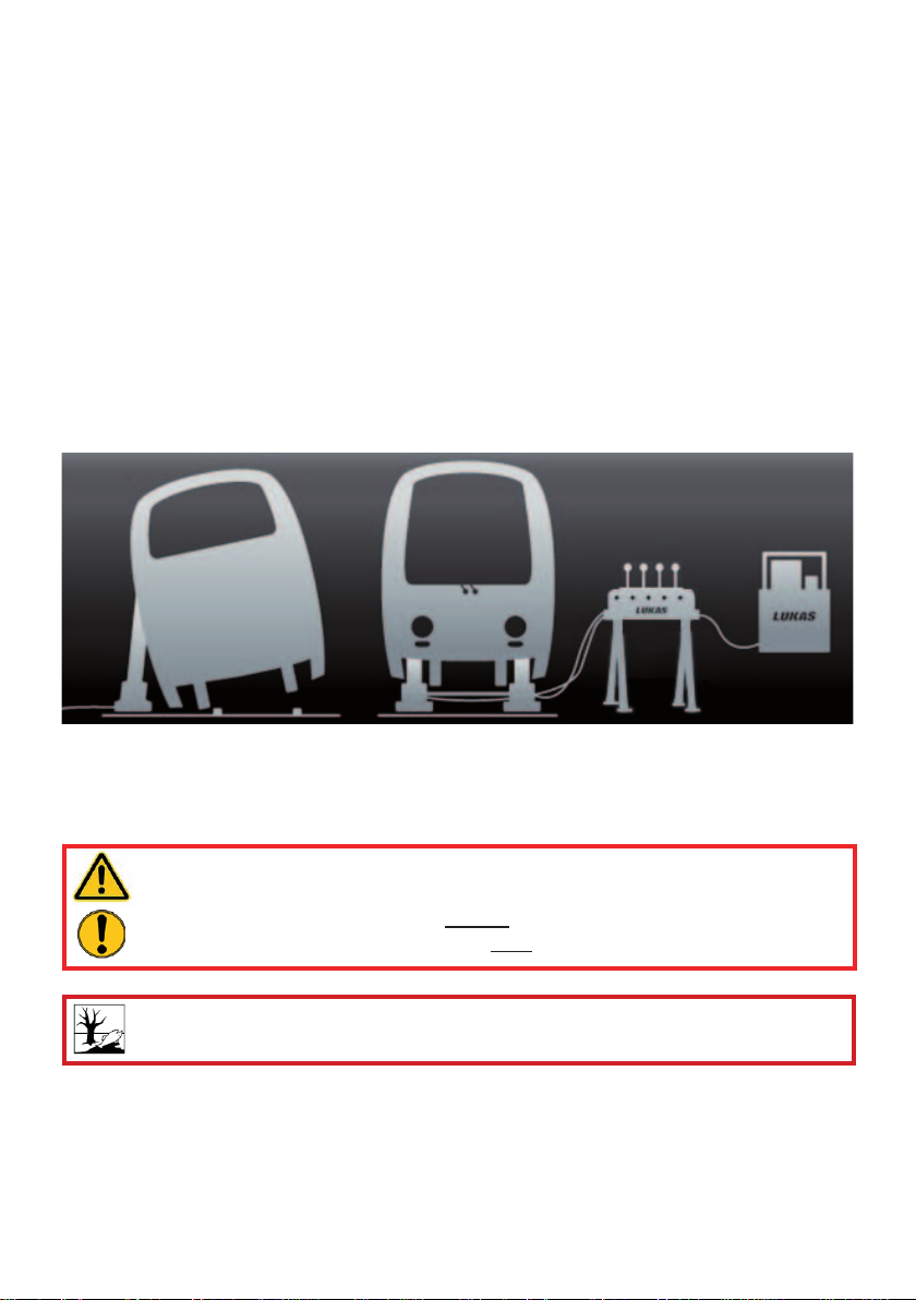
3. Proper use
LUKAS control tables are especially designed for rerailing technology. They serve to
control the deployed hydraulic lifting and traversing equipment for rerailing, erection and
maintenance work on rail-bound vehicles.
When carrying out any work, use the control tables described here and the connected hoses
and equipment to ensure that you yourself, the involved and uninvolved persons in the
proximity of the work and objects in closer proximity during the lifting and traversing process
are not endangered.
Y ou can obtain accessories and replacement parts for the control tables from your authorised
LUKAS dealer!
System overview
Rail-bound vehicle erection
WARNING / CAUTION / ATTENTION!
The safety instructions in this operating instruction manual concerning the site of
erection and type of erection must always be observed!
The Type CU LUKAS control tables are not explosion-protected!
ATTENTION!
Watch out vigilantly for any leaks in order to avoid threats to the environment.
lifting cylinders and the
LUKAS traversing system
8
Control table
UnitLifting and rerailing with
4. Components and functions
4.1 Description
The CU range of control tables consist of a control desk with support frame and a large
number of valves. The valves are actuated by control levers. The control levers automatically
return to the neutral or middle position when released (dead man's handle - depressurised
circulation with hydraulic load holding).
The control table has been developed for connection of double-acting cylinders, but singleacting cylinders can also be connected and controlled to a limited extent. If necessary you
may need to consult LUKAS or one of their authorised dealers.
The control tables are rigidly mounted on a support frame that can be folded fl at for space-
saving storage.
Pressure gauges are mounted on the control tables as standard. Each pressure gauge
shows the pressure generated by each individual pump circuit and which is present at the
control table via the power unit.
The hydraulic power packs developed for the single control table are 2POWER packs with
two circuits, and the power packs developed for the double control table are 4POWER packs
with four circuits.
4.2 Hydraulic supply
Only LUKAS hydraulic power packs may be used to drive the equipment.
If the pump unit supplying the pressure is from a different manufacturer you need to make
sure that it is made in accordance with the stipulations laid down by LUKAS. If this is not the
case, dangers can arise that cannot be attributed to LUKAS.
Ensure in particular that the maximum permissible operating pressure for the connected
LUKAS equipment is not exceeded.
NOTE:
Before using pumps and power packs from a different manufacturer, you must
always contact LUKAS or an authorised dealer.
The connection to the hydraulic pump providing the supply and to the hydraulic working
equipment is by hoses that are connected by couplings.
ATTENTION!
Because of the back-pressure in the hoses, the maximum overall length of
the hoses from the power pack via the control table to the working equipment
must be 20 m (66 ft.). If necessary, it is, however, possible to use longer hoses.
However, each individual case must be agreed with LUKAS or with an authorised
dealer, in order to take account of the local conditions if necessary.
9

4.3 Installation of the control table
1a
1b
6
12
5
4
8
1 Control lever - lifting/lowering
1a Control lever black -
traversing cylinder
1b Control lever red - locking
pin
2 Control lever - preselection
valve
3 Pressure gauge
4 Transporting handle
5 Stop knob for swivel foot
6 Operating desk
7 Swivel foot left/right
8 Footplate - adjustable in
height
9 Connection for double-acting
hydraulic equipment (4x)
10 Connection hose with
sleeve for unit
11 Connection hose with nipple
for unit
12 Cut-out for hanging up the
hose ends
1
Operating side:
3
2
5
7
Working side:
7
9
11
10
10

4.4 Functions and controls available at the control desk
Red switching lever for anchoring
cylinder (holds the traversing unit),
alternatively LIFTING/LOWERING if
there is a lifting cylinder connected
Switching valve
for pressure relief
of the anchoring
cylinder before
uncoupling
Switching valve
for pressure relief
of the traversing
cylinder before
uncoupling
Switching lever for lateral movement/
sliding with connected traversing
cylinder, alternatively LIFTING/
LOWERING with connected lifting
cylinder
LIFTING/LOWERING
Lifting cylinder
LIFTING/LOWERING
Lifting cylinder
Pressure gauge
ATTENTION!
Even after having
switched the pressure
relief valve to position
“O”, cylinders can move
in or out (lower/lift).
Pressure
gauge
The selection lever (preselection valve) for pressurisation of the left or right side of the desk (after changing
over the selection lever to one side the right pressure
gauge shows the current pressure in the right-hand
circuit, and the left pressure gauge shows the pressure in the left-hand circuit)
11

Controlling double-acting hydraulic equipment
The double-acting hydraulic equipment is actuated by 4 or 8 (on the CU 4DW) control
levers on the drive side. The CU 4DW control table corresponds to two CU 2DV control
units mounted on a larger control table. Operating the CU 4DW control table is analogue to
that of the CU 2DV.
On the operator side , on the left, there are two smaller valve switching levers next to the
control levers (the black and red control lever ends), that are for de-pressurising before
uncoupling the anchor cylinder (control lever with red lever end) and the traversing
cylinder. Lifting cylinders can also be connected here if a DUO movement cylinder is not
used, or if one will only be used at a later time.
Proceed as follows if there is system pressure on the right-hand side and the connection
hoses cannot be coupled:
1. Connect the power pack,
2. create readiness for operation of the power pack (depends on the type)
3. Move the switching levers for pressurisation on the right-hand side to the pressure
position,
4. Set both control levers to lowering/retraction for three seconds (see illustration below)
This depressurises the system on the right on the operator side and the hoses can then be
coupled.
Pressure, or residual pressure in the supply circuit on the right of the control desk can be
created by actuating the <Lifting/Extending> control lever without connected end units. The
<Lifting/Extending> function contains the hydraulic load-holding function in order to hold the
load in its position by the system pressure. The pressure dissipates when moving downwards.
12

Moving the control lever to the middle (preselection valve is actuated) on the operator side,
in each case the left or right side is pressurised. After moving the middle lever to one side,
the condition of the other side remains static.
5. Erection and start-up
The control tables must be set up at a suffi ciently safe distance from the loads to be lifted
or moved.
Both the load and the operating equipment must be easily observed from the control table.
Make sure that the control table is standing securely. If necessary, pack it up with suitable
materials.
NOTE:
Make sure that you set up all other components being used in accordance with
the separate operating instructions for these components.
ATTENTION!
When commissioning you must observe the instructions and regulations in the
separate operating instructions of the additional components that are used in
your rerailing system!
Work to be carried out before commissioning:
Before commissioning you must carry out a visual check for damage and leaks on all
components being used. Damaged components must not be used and must be replaced!
The hydraulic components must be bled to remove air before commissioning!
Commissioning:
CAUTION / ATTENTION!
Secure the vehicle to be rerailed in accordance with the regulations to prevent its
rolling away, slipping and tipping over!
Procedure:
1. Set up all the components being used in accordance with the corresponding operating
instructions. When setting up you must comply with all the applicable standards, guidelines,
regulations and statutes! Then connect all the hydraulic components as described in the
Chapter "Connecting the hydraulic equipment".
CAUTION / ATTENTION!
Make sure that there are no persons remaining in the danger area!
13

5.1 Folding out the support frame
The support frame ensures secure mounting of the control unit and allows to operator to
work standing upright.
The control unit is delivered in the folded transport position.
Proceed as follows to erect the system (two people required):
1. Lift the control table with the handles at the side. Place your hands in the handles on the
left and right, that are located opposite the locking knob, in each case, in order fi rst to
fold out the lower support frame.
2. Release the support frame lock by pushing the locking knob with your thumb (see
illustration). The support frame swings down up to the stop.
ATTENTION!
Make sure that the support frame does not hit your knee when it swings down
if you have bent your legs in order to balance the load on your lower arms with
your thighs.
3. Pull the support frame back until the locking knob engages and the system is secure.
4. Proceed in the same way on the second folded support frame.
5. Folding the two support frames is carried out in reverse sequence.
14

5.2 Connection of the working equipment
On the double-acting hydraulically-actuated working equipment, there is, on the
pressure supply side (with cylinders: the cylinder base side) a quick-disconnect nipple,
and, on the return side (piston rod side) a quick-disconnect sleeve; and these are connected
to the control table using a pair of extension hoses. On the hose ends we connect, in each
case, a nipple on the sleeve on the end equipment and a sleeve on the nipple on the end
equipment to prevent mix-ups.
Y ou can also place coloured clip rings (supplied with the equipment) on the kink-preventer to
make it visually easier to make connections to several end equipment items.
A quick-disconnect nipple is provided on the single-acting hydraulically-actuated working
equipment to provide a pressure supply. they are connected to the control table via
an extension hose. If you are using earlier versions of single-acting cylinders, LUKAS
recommends that you contact LUKAS or an authorised dealer.
The connection between the control table and the hydraulic power pack is either via
the fi xed short connection hoses, in order to place the power pack under the control
table, or via hose extensions in order to allow the power pack to remain on the vehicle,
for example, and only the control table needs then to be transported to the site of
deployment. The hose extension pairs are supplied in various lengths. The individual hoses
can, if required, also be marked with coloured snap rings to make it easier to allocate the
hoses. (For specifi c details, please consult the LUKAS range of accessories or contact your
LUKAS dealer.)
WARNING / CAUTION / ATTENTION!
Prior to connecting the devices, ensure that all the components
being used are suitable for the maximum operating pressure
of the unit! In case of doubt you must consult LUKAS directly!
5.3 Coupling the quick-disconnect couplings
The device is connected to the hydraulic pump without risk of misconnection using
monocoupling halves (female and male coupling).
X
Y
Before coupling, remove dust caps and then pull back and hold the locking sleeve of the
female coupling half (position X). Connect the male and female couplings and release the
locking sleeve. Then turn the locking sleeve to position Y. The connection has been made
and locked. Uncoupling is done in the reverse order. Coupling of the devices is only possible,
when the hoses are depressurized. For dust protection, the supplied dust caps must be
refi tted.
ATTENTION!
Always connect the return line fi rst and then the supply line!
15

NOTE:
Coupling of the devices is only possible, when the hoses are depressurized.
For dust protection, the supplied dust caps must be refi tted.
WARNING / CAUTION / ATTENTION!
Some quick-disconnect couplings have special functions.Therefore, you must
not unscrew them from the hoses or swap them over!
6. Dismantling the equipment / deactivation following operation
WARNING / CAUTION / ATTENTION!
Before dismantling the rerailing equipment, please ensure that the moved load is
in a stable and fi rm position!
Procedure:
1. Retract all the hydraulic cylinders and traversing cylinders to just a few mm)* protrusion
(base position) when the work is complete. This relieves the hydraulic and mechanical
stress on the equipment.
2. Then switch the hydraulic unit off.
3. Switch the two levers on the control table of the manual pressure switch-off valves to the
0 position (turn clockwise up to the stop). In addition, switch all the other levers in both
directions (lift/lower). Operating pressure at the pressure gauge 0 bar/psi.
4. You can then dismantle the system in accordance with the instructions in Chapter "Connecting the hydraulic equipment" and the separate instructions for the rerailing equipment involved.
ATTENTION!
The operating pressure in the system must be dissipated before uncoupling
the hoses. When the rerailing work is complete you must release the operating
pressure in the installation/system.
A visual inspection must be carried out after every use, but at least once a year. Every
three years or if there is any doubt regarding the safety or reliability of the equipment, a
functional test must also be performed. (Please also observe the relevant valid national and
international regulations pertaining to service intervals of hydraulic equipment).
ATTENTION!
Clean off any dirt before checking the equipment!
WARNING / CAUTION / ATTENTION!
T o perform maintenance and repairs, personal protection equipment appropriate
for the work is an absolute requirement.
16

Inspections to be carried out:
Visual Inspection
• Control table free from damage and deformation
• General tightness (leaks),
• Handle present and secure,
• All screwed connections tight
• Type plate, warning signs and other markings present and legible,
• Couplings must be easy to couple,
• Dust protection caps must be available,
• All accessories used not damaged
Functional test
• Perfect ease of movement of the control levers
• No unusual noises
7. Maintenance and service
7.1 General information
Service work may only be performed by the device manufacturer or by personnel trained by
the device manufacturer and authorised LUKAS dealers.
Only LUKAS spare parts may be used to replace all components (see spare parts list) since
special tools and compliance with, assembly instructions, safety aspects and inspections are
required (see also chapter "Maintenance and Servicing").
During the assembly work, pay particular attention to the cleanliness of all components
because dirt can damage the equipment!
WARNING / CAUTION / ATTENTION!
Protective clothes must be worn when repairs are being carried out, since the
devices may also be pressurised when not in operation.
NOTE:
You should always contact LUKAS or an authorised dealer before using
couplings from another manufacturer.
A TTENTION!
Because LUKAS devices are designed for the highest performance, only components
may be replaced that are listed in the spare parts lists of the corresponding device.
Other components in the device may only be replaced if:
- You have participated in an appropriate LUKAS service training course.
- You have the express permission of LUKAS Customer Service (after request,
verifi cation that permission may be granted. An examination in each individual
case is necessary!)
7.1.1 Care instructions
The exterior of the equipment is to be cleaned from time to time in order to protect it from
external corrosion. Oil is to be applied to the metallic surfaces.
7.1.2 Function and load test
If there is any doubt regarding the safety or reliability of the equipment, a function and load
test must also be performed.
17

7.1.3 Replacing the hydraulic fl uid
After approx. 200 deployments, but after three years at the latest, replace the hydraulic fl uid
in the entire rerailing installation.
Because of the small quantity of hydraulic fl uid in the control table, separate fl uid
replacement on the control table is not required. It is adequate to fl ush the entire
installation with the new hydraulic fl uid during fl uid replacement. However, all the valves
need to be actuated (if necessary connect the supply and return lines of each valve
in order to fl ush).
ATTENTION!
Always perform the change of the hydraulic fl uid over a collection tank and
dispose of the collected fl uid in a proper manner!
ATTENTION!
The hydraulic fl uid must be completely replaced if the application conditions
(ambient temperatures) change substantially. When selecting a suitable
hydraulic fl uid, please refer to Chapter “Hydraulic fl uid recommendations” for
the relevant rerailing equipment.
7.2 Repairs
7.2.1 Coupling replacement
The couplings must be replaced if:
- there is external damage,
- the locking does not function,
- hydraulic fl uid continues to leak in the coupled/uncoupled state.
WARNING / CAUTION / ATTENTION!
Never repair couplings: they must be replaced by genuine LUKAS parts!
During assembly tighten the coupling to a torque of M
= 40 Nm.
A
Procedure:
1. Remove the coupling.
2. Place a new coupling in position and tighten to a torque of M
= 40 Nm.
A
7.2.2 Decals
All damaged and/or illegible decals (safety notices, type plate etc.) must be replaced.
Procedure:
1. Remove damaged and/or illegible decals.
2. Clean surfaces with acetone or industrial alcohol.
3. Affi x new decals.
T ake care to affi x the labels in the correct positions. If this is no longer known, you should ask
your authorised dealer or contact LUKAS directly.
18

8. Troubleshooting
Fault Check Cause Solution
Connected
working equipment
moves slowly
or jerkily when
activated
The connected
working equipment
does not move
when actuated
and no pressure
indication on
the control table
pressure gauge.
The connected
working equipment
does not move
when actuated
but pressure
indication on
the control table
pressure gauge.
Connected
working equipment
does not apply the
specifi ed force.
Are the hoses
connected
properly?
Does the pump
unit work?
Are the hoses
connected
properly?
Does the pump
unit work?
Hydraulic fl uid
level in the
supplying pump?
Check the
operating pressure
on the control
table pressure
gauge
Check working
equipment
Air in the hydraulic
system
Working unit
defective.
Hose connection
to hydraulic power
pack not made, or
made incorrectly.
Pump unit not
switched on or
defective.
Control table
defective
Problem with
the working
equipment.
Insuffi cient
hydraulic fl uid in
the pump
Pressure supply
has too low
pressure
Working
equipment
defective
Vent the hydraulic
system
Consult the
separate operating
instructions for the
working equipment.
Connecting hose
assemblies properly.
Consult the
separate operating
instructions for the
pump unit.
Have it repaired
by an authorised
dealer or directly by
LUKAS.
Consult the
separate operating
instructions for the
working equipment.
Top up hydraulic
fl uid and bleed the
air
If possible, increase
the max. operating
pressure on the
hydraulic unit to
max. operating
pressure of the
cylinder or use
another hydraulic
unit with a suffi cient
max. operating
pressure.
Consult the
operating
instructions for the
working equipment.
19

Hoses cannot be
coupled
Leak from the
couplings
Is the coupling
damaged?
Lines are under
pressure because
there is pressure in
the system
Coupling defective Coupling must
Coupling defective Coupling must
Remove the
pressure or residual
pressure (see Page
12)
be replaced
immediately
be replaced
immediately
Cylinders
automatically
lower under load
Contact an authorised LUKAS dealer or the LUKAS Customer Service Department directly
if the malfunctions cannot be rectifi ed.
The address for the LUKAS Customer Service department is:
LUKAS
Weinstrasse 39, D-91058 Erlangen, Germany
PO Box 2560 D-91013 Erlangen
Tel.: (+49) 09131 / 698 - 348
Fax.: (+49) 09131 / 698 - 353
Hydraulik GmbH
Check position
of pressure relief
valves
Operating error Switch pressure
relief valve to
position I
20

9. Technical data
Because all values are subject to tolerances, there may be small differences between the
data for your device and the data in the following tables!
9.1 Control unit CU 2DV
Device type CU 2DV Value Units Remarks
Item number 70-70-10
Dimensions l x w x h 1030 x 640 x 1112 mm set up
40.6 x 25.2 x 43.8 in.
Dimensions l x w x h 1030 x 640 x 450 mm folded
40.6 x 25.2 x 17.7 in.
Operating pressure max. 53 MPa
7700 psi
Control valve Lifting 2 Number
Control valve traversing/lifting 1 Number
Control valve Locking/lifting 1 Number
Hydraulic
connections
Ambient
temperature
Weight 43.5 kg
Specifi cation of
hydraulic fl uid
NW 06 quick-
disconnect-
coupling
-20 … +55 °C
-4 … 131 °F
95.9 lbs.
HM 10 ISO 6743-4
21

9.2 Control unit CU 4 DVV
Device type CU 4DVV Value Units Remarks
Item number 70-20-20
Dimensions l x w x h 1310 x 640 x 1112 mm set up
51.6 x 25.2 x 43.8 in.
Dimensions l x w x h 1215 x 640 x 450 mm folded
47.8 x 25.2 x 17.7 in.
Operating pressure max. 53 MPa
7700 psi
Control valve Lifting 4 Number
Control valve traversing/lifting 2 Number
Control valve Locking/lifting 2 Number
Hydraulic
connections
Ambient
temperature
Weight 68 kg
Specifi cation of
hydraulic fl uid
NW 06 quick-
disconnect-
coupling
-20 … +55 °C
-4 … 131 °F
150 lbs.
HM 10 ISO 6743-4
9.3 Operating and storage temperature ranges
Operating temperature [°C] / [°F] -20 … +55 -4 … +131
Environmental
temperature (device in
operation)
Storage temperature
(device not in operation)
[°C] / [°F] -25 … +45 -13 … +113
[°C] / [°F] -30 … +60 -22 … +140
22

10. EC Declaration of Conformity
23

11. Notes
24

252627


Please dispose of all packaging materials and
removed items properly.
LUKAS
A unit of the IDEX Corporation
Hydraulik GmbH
Weinstrasse 39, D-91058 Erlangen, Germany
Tel.: (+49) 0 91 31 / 698 - 0
Fax.: (+49) 0 91 31 / 698 - 394
e-mail: lukas.info@idexcorp.com
www.lukas.com
Made in GERMANY
© Copyright 2014 LUKAS Hydraulik GmbHCU_2DV_4DVV_manual_1490000085_en.indd
Subject to changes
 Loading...