

Page 1
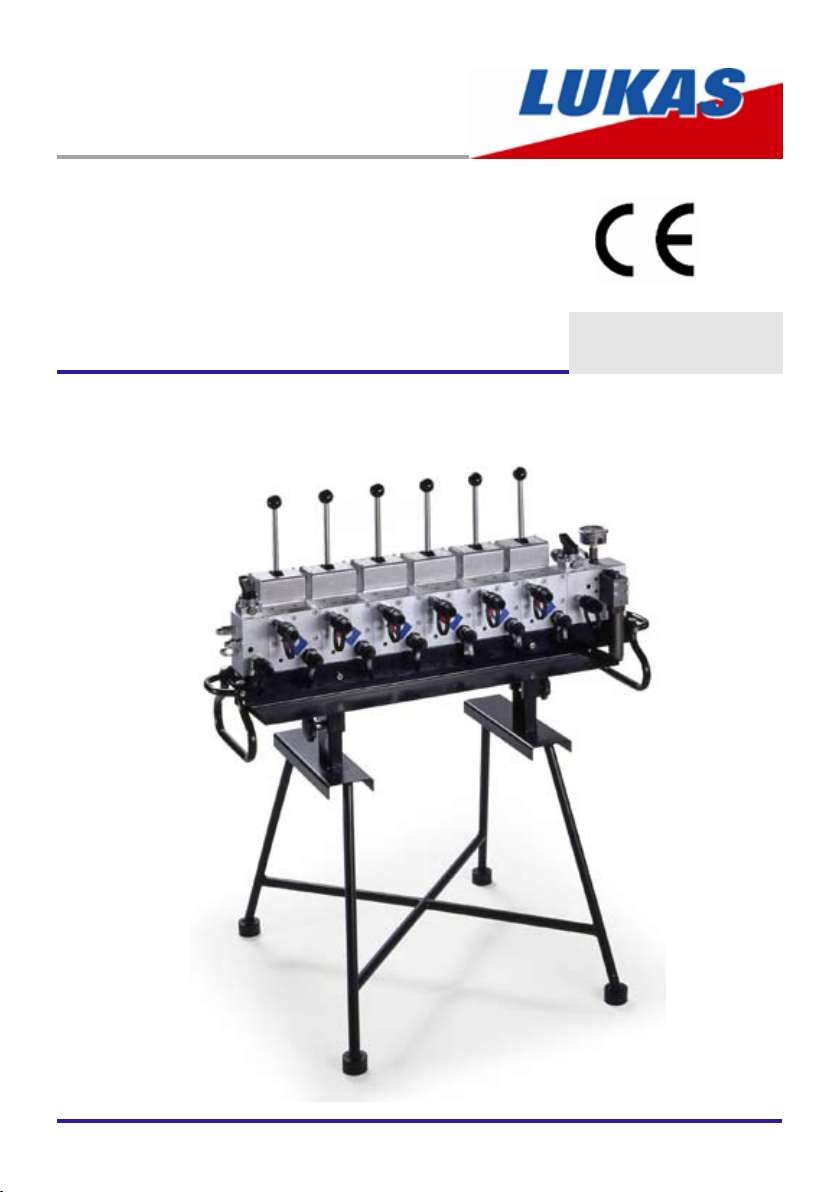
Operating instructions
Rerailing Equipment
Control desks (model CT7)
84072134485 GB
Edition 08.2009
(Translation of the original operating instructions)
Page 2

2
Page 3

3
Content Page
1. Hazard classes 4
2. Product safety 5
3. Proper use 8
4. Functions and performance 9
4.1 Description 9
4.2 Hydraulic supply 9
4.3 Overview 10
4.4 Hydraulic circuit diagrams for standard control desks 11
4.5 Optional accessories 14
5. Connection of hydraulic devices 14
5.1 Basic information 14
5.2 Connection of quick-connect couplings 15
6. Operation 16
6.1 Setting up the control desk 16
6.2 Start-up 16
6.3 Control desk controls 17
7. Dismantling the equipment / deactivation following operation 18
8. Maintenance and service 19
9. Repairs 19
9.1 General 19
9.2 Preventive service 20
9.3 Repairs 21
10. Troubleshooting 22
11. Technical data 24
11.1 Control unit 24
11.2 Pedestal 24
11.3 Control desk (control unit + pedestal) 25
11.4 Recommendedhydraulicuids 25
11.5 Operating temperature and storage temperature ranges 25
12. EC Declaration of Conformity 26
13. Notes 27
Page 4
4
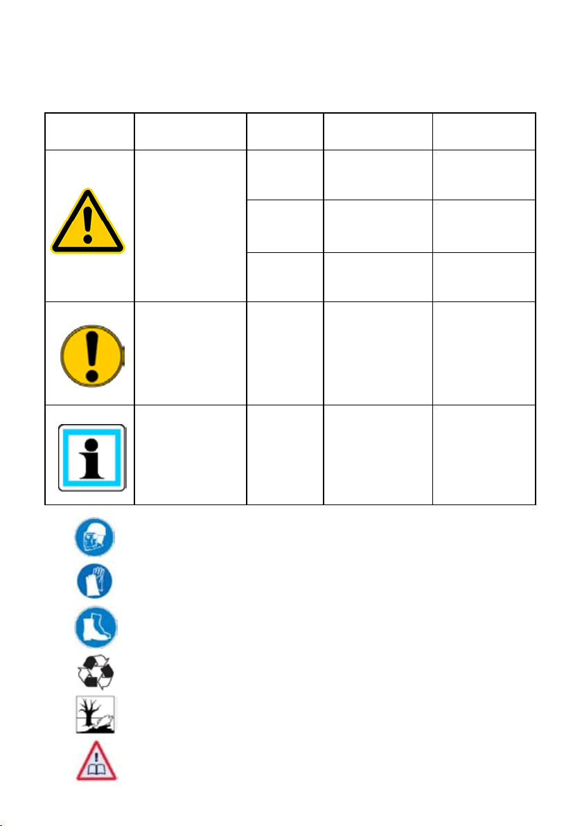
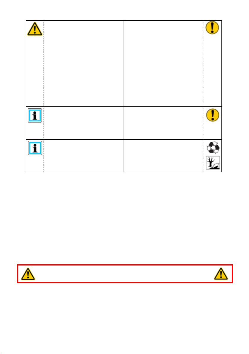
Hazard classes1.
We distinguish between various categories of safety instructions. The table below gives you
an overview of the assignment of symbols (pictograms) and key words to the specic hazard
and possible consequences.
Pictogram
Damage / injury
to
human
device
- REMARK
Key word Denition Consequences
DANGER! Immediate danger
WARNING!
CAUTION!
CAUTION!
Potentially
dangerous
situation
Less dangerous
situation
Danger of damage
to device /
environment
Advice for
application and
other important /
useful information
and advice
Death or major
injury
Potential death or
major injury
Minor or slight
injury
Damage to the
equipment,
damage to the
environment,
damage to
surrounding
materials
No injury /
damage to
persons /
environment /
equipment
Wear helmet with face protection
Wear safety gloves
Wear safety shoes
Proper recycling
Observe principles of environmental protection
Read and observe operating instructions
Page 5
5
Product safety2.
LUKAS products are developed and manufactured in order to guarantee the best performance
and quality when used properly.
Operator safety is the most important aspect of the product design. Moreover, the operating
instructions are intended to ensure LUKAS products are used safely.
The generally applicable legal and other binding regulations pertaining to the prevention of
accidents and protection of the environment apply and are to be complied with in addition to
the operating instructions.
The equipment may only be operated by persons with appropriate training in the safety
aspects of such equipment – otherwise, there is a danger of injury occurring.
We would like to point out to all users that they should read the operating instructions carefully
before using the equipment and comply with the instructions there without restriction.
We further recommend that a qualied instructor train you in the use of the product.
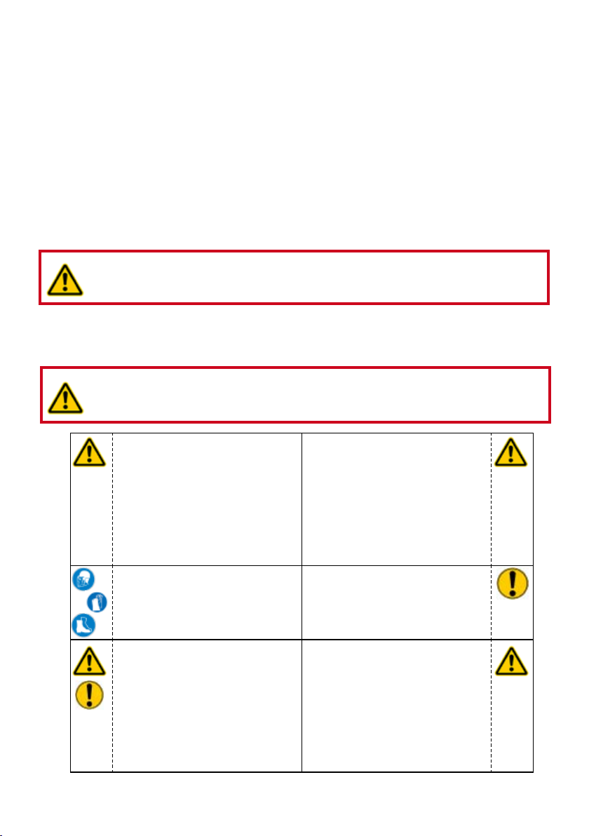
WARNING / CAUTION!
The operating instructions for the hoses, the accessories and the connected
hydraulic equipment must also be observed.
Even if you have already received instructions on how to use the equipment, you should still
read through the following safety instructions once again.
WARNING / CAUTION!
Ensure that the accessories and connected equipment used are suitable for
the maximum operating pressure.
Please ensure that no body
parts or clothing get stuck
between the visibly moving
parts.
Wear protective clothing, safety
helmet with visor, safety shoes
and protective gloves
The department responsible
is to be informed immediately
of any changes (including to
the operating behaviour). If
necessary, the equipment is to
be shut down immediately and
secured.
It is prohibited to work under
load if this load is lifted
exclusively by hydraulic
equipment. If this work
is absolutely imperative,
additional mechanical supports
must be used.
Inspect the equipment before
and after use for visible defects
or damage.
Inspect all lines, hoses and
screwed connections for
leaks and externally visible
damage. If necessary,
repair immediately. Squirting
hydraulic liquids can result in
injuries and res.
Page 6
6
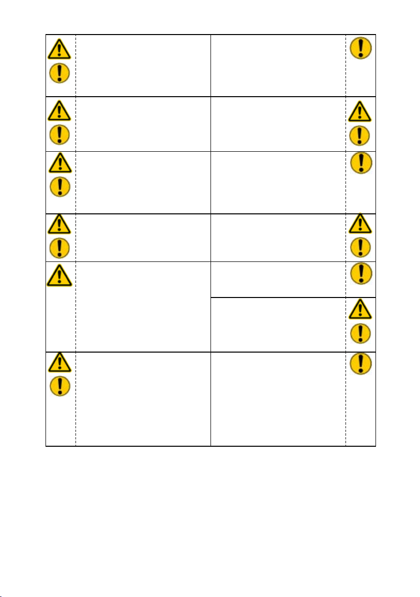
In the event of malfunctions,
immediately shut down the
equipment and secure it. The
malfunction is to be repaired
immediately.
Do not carry out any changes
(additions or conversions)
to the equipment without
obtaining the prior approval of
LUKAS.
Comply with all the instructions
regarding safety and danger
on the equipment and in the
operating instructions.
Any method of operation which
impairs safety and/or stability
of the equipment is prohibited.
Safety devices may never be
deactivated.
Before the equipment is
switched on / started up, and
during its operation, it must
be ensured that nobody is
endangered by the operation of
the equipment.
When working close to live
components and cables,
suitable measures must be
taken to avoid current transfers
or high-voltage transfers to the
equipment.
All the instructions regarding
safety and danger on the
equipment are to be kept
complete and in a legible
condition.
Comply with all specied
dates or dates specied in
the operating instructions
pertaining to regular checks /
inspections of the equipment.
The maximum operating
pressure marked on the
equipment must not be
exceeded.
Only original LUKAS
accessories and spare parts
may be used for repairs.
During all work and transport
operations involving the
equipment, take care not to trip
and become caught in hose
loops.
The build-up of static charge
with the potential consequence
of spark formation is to be
avoided when handling the
equipment.
Page 7
7
The equipment is lled with
hydraulic uid. These hydraulic
uids can be harmful to your
health if swallowed or if their
vapours inhaled. Direct contact
with the skin is to be avoided
for the same reason. Please
also note that hydraulic uids
can also have a negative effect
on biological systems.
When working with or storing
the equipment, ensure that the
function and the safety of the
equipment are not impaired by
the effects of extreme external
temperatures and that the
equipment is not damaged in
any way. Please note that the
equipment can also heat up
over a long period of use.
Ensure adequate lighting when
you are working.
Always keep these operating
instructions within reach where
the equipment is used.
The generally applicable, legal and other binding national and international regulations
pertaining to the prevention of accidents and protection of the environment apply and are to
be implemented in addition to the operating instructions.
Before transporting the
equipment, always ensure that
the accessories are positioned
in such a way that they cannot
cause an accident.
Ensure the proper disposal
of all removed parts, leftover
oil and uid, and packaging
materials.
WARNING / DANGER / CAUTION!
The equipment is to be used exclusively for the purpose stated in the operating
instructions (see chapter "Proper use"). Any form of use beyond this is not considered
proper use. The manufacturer / supplier is not liable for any damages resulting from improper
use. The user bears sole responsibility for such use.
Observance of the operating instructions and compliance with the inspection and maintenance
conditions are covered by the denition of proper use.
Never work when you are overtired or intoxicated.
Page 8
8
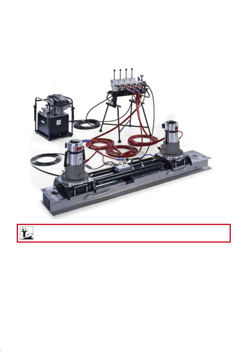
Proper use3.
LUKAS control desks have been developed specically for rerailing operations. They are
intended to control the hydraulic jacks and pushers used in the event of a railway vehicle
derailment.
The accessories required for the derailment incident concerned must be used (depending
on the variant, e.g. pedestal).
CAUTION!
To minimise the risk to the environment, remedy leaks as soon as possible.
Accessories and spare parts for the control desks are available from your authorised LUKAS
dealer.
Page 9
9
Functions and performance4.
4.1 Description
The control desks in the CT7 model series comprise a number of valves housed in a control
block. The valves are controlled by means of control levers.
Depending on the version, up to 6 double-acting and 2 single-acting hydraulic devices can
be connected and controlled without the need for a separate controller.
The attached, manually operated pressure shut-off valve opens and closes the supply to the
control valves. With the manual pressure shut-off valve in the “closed” position, the ow to
WARNING / DANGER / CAUTION!
The manual pressure shut-off valve closes only the connection to the hydraulic
unit to be supplied.
It is NOT provided as an “emergency stop” function. This means that the
connected hydraulic devices could still move if one of the control levers were
operated. This could happen if residual pressure in the system or external loads
were to act on the connected hydraulic devices.
the hydraulic pump is automatically depressurised.
The control desks are usually mounted on a separate pedestal or secured directly to the unit
frame. LUKAS control desks are normally always delivered mounted on a pedestal or tted
to a frame. To nd out more, please contact your authorised LUKAS dealer.
The control desk also features a pressure gauge on the inlet block as standard. This pressure
gauge indicates the pressure acting on the control desk from the unit.
4.2 Hydraulic supply
Only LUKAS motor pumps are permitted to be used to drive the devices.
If an other-make pump power pack is used, it is important to ensure that it complies with
LUKAS specications, as otherwise dangerous situations beyond the control of LUKAS
could arise. Particular care must be taken to ensure that the maximum permissible operating
pressure of the connected LUKAS devices is not exceeded.
REMARK:
Before you use pumps of a different manufacturer, you must contact LUKAS or
an authorised dealer.
The connection to the supplied hydraulic pump and to the implements is established by
means of hose lines, which are connected to each other by couplings.
CAUTION!
Due to ram pressures in the hose lines, the maximum overall length of the hose
lines, from the unit to the control desk to the hydraulic device, is limited to 40 m
(131.2 ft.).
Long hose lines between the implement and control desk or unit and control desk
may result in delayed movement of the hydraulic implements (particularly in the
event of the automatic return of single-acting implements).
For work involving long hose lines at low ambient temperature, we recommend
theuseofahydraulicuidwithalowviscosity.
Page 10

10
4.3 Overview
Operato r ' s
4
5
1
3
6
W o r k i n g
4
7
9
1 Switch valves
2 Switch lever
3 Manual pressure
shut-off valve
4 Pushbutton valve
5 Pressure gauge
6 Connection for hydraulic
supply
7 Connection for single-
acting hydraulic devices
(e.g. anchor cylinders)
8 Connection for double-
acting hydraulic devices
9 Pedestal
9
2
5
4
7
8
Page 11

11
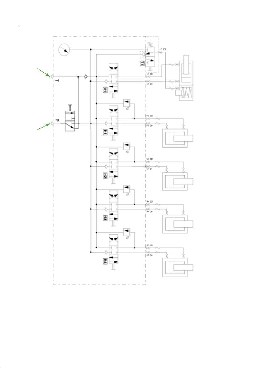
4.4 Hydraulic circuit diagrams for standard control desks
CT7 - 6/3DV:
30 MPa30 MPa30 MPa
Supply line from
hydraulic unit
Return line to
hydraulic unit
Page 12
12
CT7 - 6/4DV:
Return line to
hydraulic unit
Supply line from
hydraulic unit
30 MPa 30 MPa 30 MPa 30 MPa
Page 13

13
CT7 - 6/4DVV:
30 MPa 30 MPa 30 MPa 30 MPa
Supply line from
hydraulic unit
Return line to
hydraulic unit
Page 14

14
4.5 Optional accessories
4.5.1 Pedestal
The pedestal is intended to provide safe support for the control unit and to enable the
operator to work standing up.
Thecontrolunitisttedtothepedestalasfollows:
1. Loosen connection “F” approximately 15 mm (in.)
on pedestal “G”.
2. Fit control unit “J”, mounted on leg “H”, onto the
pedestal and retighten connection “F” on both sides.
3. Removal in reverse order.
4.5.2 Pressure gauge
To supplement the pressure gauge already tted to the control unit, it is possible to t an
additional pressure gauge for each pressure line so that you can read the pressure acting on
the implement. There are two possible installation arrangements. One directly between the
control unit and the hose line of the individual pressure line outlets on the switch valves, and
one that requires an extra measurement hose, which taps the pressure directly at the switch
valve. The measurement hose solution requires a special mounting plate for the pressure
gauge units. To nd out more about optional pressure gauges, please contact your authorised LUKAS dealer.
J
H
F
G
Connection of hydraulic devices5.
5.1 Basic information
Double-acting, hydraulically operated implements are tted with a male quick-disconnect
coupling on the pressure supply side (with cylinders: cylinder bottom end) and a female
quick-disconnect coupling on the return side (with cylinders: piston rod end); these are
connected to the control desk by a pair of extension hoses (nominal diameter DN 6).
Single-acting, hydraulically operated implements are tted with a male quick-disconnect
coupling on the pressure supply side; this is connected to the control desk by an extension
hose line (nominal diameter DN 10).
The connection between the control desk and the hydraulic unit is always established by
means of extension hose lines (nominal diameter DN 10).
All LUKAS extension hose pairs/lines are colour-coded and equipped with quick-disconnect
couplings to minimise the possibility of misconnection.
Page 15

15
WARNING / DANGER / CAUTION!
Before connecting equipment, make sure that all the components
used are suitable for the maximum operating pressure of the
pump unit. In cases of doubt, you must consult LUKAS directly.
5.2 Connection of quick-connect couplings
The device connects to the hydraulic pump by means of individually coded quick-connect
coupling halves (plug and socket).
X
Before coupling, remove the dust protection caps, then pull back and hold the locking sleeve
of the female coupling (position X). Fit the socket and plug together and release the locking
sleeve. Then turn the locking sleeve to position Y. The connection has now been made and
locked. Disconnection is made in the reverse order. Hoses can be connected only when
depressurised. To protect against dust, the accompanying dust protection caps must be
replaced.
CAUTION!
Always connect the return hose rst and then the supply hose.
REMARK:
Hoses can be connected only when depressurised.
To protect against dust, the accompanying dust protection caps must be replaced.
WARNING / DANGER / CAUTION!
Some quick-disconnect couplings have special functions. Therefore it is not
permitted to screw them off the hoses or to swap them.
Page 16

16
Operation6.
6.1 Setting up the control desk
Control desks must be set up at a safe distance from the load to be lifted or pushed.
Both the load and the implements must be clearly visible from the control desk position.
Make sure that the control desk has stable footing. Use suitable material for support if
necessary.
REMARK:
Set up all other necessary components as described in the separate operating
instructions for these components.
Check that the manual pressure shut-off valve is closed (home position) and then connect
the hydraulic unit to the implements.
6.2 Start-up
CAUTION!
During start-up, observe all information and instructions in the separate operating
instructions for the other components of your rerailing system.
Preparations before start-up:
Before start-up, all components must be visually inspected for damage and leaks. Damaged
components must not be used and must be exchanged.
Hydraulic components must be bled before start-up takes place.
Start-up:
DANGER / CAUTION!
Correctly secure the derailed vehicle against rolling away, slipping and tipping.
Procedure:
1. Set up the necessary components as described in the separate operating instructions for
these components. During set-up, observe all applicable standards, directives, laws and
regulations. Now connect up all hydraulic components as described in the “Connection of
hydraulic devices” chapter.
DANGER / CAUTION!
Make sure that nobody is present in the danger zone.
Page 17

17
2. Then start the hydraulic unit.
3. Move the lever on the manual pressure shut-off valve
into the working position (turn anti-clockwise to the
stop).
WARNING / DANGER / CAUTION!
In the interests of safety, control desk functions
should not remain enabled (manual pressure
shut-off valve opened) unless at least one
appropriately trained operator is manning the
control desk.
For emergency use, a single handle is
provided to close the pressure shut-off
valve. This shuts off the hydraulic circuit to
all implements. The pressure shut-off valve
interrupts only the hydraulic supply between
the control desk and the pump. It is NOT
provided as an “emergency stop” function.
After the hydraulic implements have been bled, your
rerailing system is ready for operation.
6.3 Control desk controls
6.3.1 Controlling single-acting hydraulic devices
To supply single-acting hydraulic devices with
hydraulic uid, you need to press the relevant button.
As soon as the button is released, uid stops
being supplied to the associated hydraulic device.
Page 18

18
6.3.2 Controlling double-acting hydraulic devices
Double-acting hydraulic devices are controlled by
control levers.
Throwing the control lever away from the operator's
side causes the lower hydraulic connection (usually
colour-coded blue) to be supplied with hydraulic uid.
Throwing the control lever towards the operator's side
causes the upper hydraulic connection (usually colour-
coded red) to be supplied with hydraulic uid.
How far the control lever is thrown determines the ow
rate in the associated line
and thus the speed of motion
of the implement.
upper hydraulic
connection
Dismantling the equipment / deactivation following 7.
operation
lower
hydraulic
connection
WARNING / DANGER / CAUTION!
Before the rerailing equipment concerned is removed, make sure that the load is
in a stable, immovable condition.
Procedure:
1. Return all implements to home position.
2. Switch off the hydraulic unit.
3. Move the lever on the manual pressure shut-off valve into the closed position (turn
clockwise to the stop). Also check the pressure on the attached pressure gauge. This
should be practically “0”.
4. You can now disassemble the system as described in “Connection of hydraulic devices”
and in the separate instructions for the rerailing equipment used.
REMARK:
Components should be disassembled in reverse order to assembly.
Page 19
19
Maintenance and service8.
A visual inspection must be carried out after each use and at least once a year regardless
of use. In addition, a function test must be carried out every 3 years, or whenever there is
any doubt as to the safety or reliability of the equipment (observe all applicable national
and international rules and regulations relating to the maintenance intervals of the hydraulic
devices).
CAUTION!
Clean off any dirt before checking the equipment.
WARNING / DANGER / CAUTION!
In order to carry out maintenance and repair work, tools appropriate for the job
and personal protection equipment obligatory
Checks to be performed:
Visual inspection
• Control desk shows no damage or deformation
• General tightness (no leaks)
• Handles present and secure
• All screw connections tightened
• Type plate, warning labels and other markings present and legible
• Couplings must be easy to couple
• Dust protection caps must be available
• All accessories undamaged
Function test
• Control levers and buttons for proper ease of movement
• No suspicious noises
Repairs9.
9.1 General
Servicing may only be carried out by the manufacturer or personnel trained by the
manufacturer and by authorised LUKAS dealers.
Only LUKAS spare parts may be used to replace all components (see spare parts list) since
special tools, assembly instructions, safety aspects, inspections might have to complied with
(see also chapter "Maintenance and service”).
During all installation work, pay particular attention to the cleanliness of all components
as contaminants could cause damage to the equipment.
WARNING / DANGER / CAUTION!
Protective clothing must be worn when repairs are being carried out, since
parts of the units can also be pressurised in an idle state.
Page 20

20
REMARK:
Before you use couplings from a different company, you must contact LUKAS or
an authorised dealer.
CAUTION!
Since LUKAS rerailing devices are designed for top performance, only those
components in the spare parts lists of the relevant unit may be replaced.
Further components in the devices may only be replaced if:
- You have participated in appropriate LUKAS service training,
- You have the explicit permission of the LUKAS customer service (on request,
check for granting permission. Check is necessary in each individual case.)
9.2 Preventive service
9.2.1 Care regulations
The exterior of the equipment is to be cleaned from time to time in order to protect it from
external corrosion. Oil is to be applied to the metallic surfaces.
9.2.2 Stress test
If there is any doubt regarding the safety or reliability of the equipment, a function and load
test must also be performed.
9.2.3Replacingthehydraulicuid
After approx. 200 deployments, but after three years at the latest, the hydraulic uid in the
entire rerailing system must be replaced.
Due to the small amount of hydraulic uid in the control desk, a uid replacement does not
need to be carried out separately here. It is sufcient to ush it with the new hydraulic uid
at the time of a uid replacement in the entire system. All valves should be actuated in the
process (if necessary, connect the supply and return lines of each valve to each other to
ush them with the new uid).
CAUTION!
During a hydraulic uid replacement, always use a suitable receptacle to collect
escaping uid and dispose of the collected uid correctly.
CAUTION!
All of the hydraulic uid in the system must be replaced if conditions of use
(ambient temperatures) vary considerably. When selecting the appropriate
hydraulic uid, please observe the “Recommended hydraulic uids” chapter.
Page 21

21
9.3 Repairs
9.3.1 Coupling replacement
The couplings must be replaced in the event of:
- external damage
- the locking device not working
- hydraulic uid continually leaking in a coupled/uncoupled state.
WARNING / DANGER / CAUTION!
Never repair couplings: they are to be replaced by original LUKAS parts.
During installation, tighten the coupling to a torque of M
= 40 Nm.
A
Procedure:
1. Remove the coupling.
2. Fit the new coupling and screw it in with a torque of M
= 40 Nm.
A
9.3.7 Labels
All damaged and/or illegible labels (safety notices, type plate, etc.) must be renewed.
Procedure:
1. Remove damaged and/or illegible labels.
2. Clean the surfaces using industrial alcohol.
3. Attach new labels.
Make sure that the labels are attached in the right position. If you are no longer sure about
this, contact your authorised LUKAS dealer or LUKAS directly.
Page 22

22
Troubleshooting10.
Trouble Check Cause Solution
Connected
implements move
slowly or jerk in
response to control
command
Connected
implements do not
move in response to
control command and
no pressure reading
on the control desk
pressure gauge.
Connected
implements do not
move in response to
control command but
a pressure reading is
shown on the control
desk pressure gauge.
Connected implement
does not produce its
rated force.
Hose lines
connected
correctly?
Pump assembly
running?
Hose lines
connected
correctly?
Pump assembly
running?
Switch position
of the manual
pressure shut-off
valve
Hydraulic uid
level in the supply
pump?
Check the
operating pressure
on the control desk
pressure gauge
Check the
implements
Air in the hydraulic
system
Defective
implement.
Hose line to
hydraulic unit
not connected
correctly.
Pump assembly
not switched on or
defective.
Manual pressure
shut-off valve in
“closed position”
Defective control
desk
Problem with the
implement.
Insufcient
hydraulic uid in
the pump
Insufcient supply
pressure
Defective
implements
Vent the hydraulic
system
Consult the operating
instructions for the
implement.
Connect the hose
lines correctly.
Consult the operating
instructions for the
pump assembly.
Switch the manual
pressure shut-off
valve to the “working
position”.
Have repaired by
authorised dealer or
directly by LUKAS.
Consult the operating
instructions for the
implement.
Top up the hydraulic
uid and bleed
If possible, increase
the max. operating
pressure at the
hydraulic unit to
the max. operating
pressure of the
cylinder or use a
different hydraulic
unit with sufcient
max. operating
pressure.
Consult the operating
instructions for the
implements.
Page 23

23
hose assembly
cannot be coupled
Leak in the couplings Coupling
damaged?
If it is not possible to rectify the malfunctions, inform an authorised LUKAS dealer or the
LUKAS Customer Service department immediately.
The address of the LUKAS Customer Service Department is:
Pressurised Switch the pump
to depressurised
circulation
Coupling defective Coupling needs to be
replaced immediately
Coupling defective Coupling needs to be
replaced immediately
LUKAS
Weinstraße 39, D-91058 Erlangen
Postfach 2560, D-91013 Erlangen
Tel.: (+49) 09131 / 698 - 348
Fax.: (+49) 09131 / 698 - 353
Hydraulik GmbH
Page 24

24
Technical data11.
As all values are subject to tolerances, there may be minor differences between the data
achieved by your equipment and the data specied in the following table.
11.1 Control unit
Designation CT7-6/3DV CT7-6/4DV CT7-6/4DVV
Ref. no. 840721344 840721345 840721346
Dimensions
(L x W x H)
Max. operating
pressure
(HP)
Max. operating
pressure
(LP)
Weight
[mm] 801 x 335 x 500 931 x 335 x 500 986 x 335 x 500
[in.] 35.5 x 13.2 x 19.7 36.7 x 13.2 x 19.7 38.8 x 13.2 x 19.7
[Mpa]* 53 53 53
[psi.] 7,687 7,687 7,687
[Mpa]* 23 23 23
[psi.] 3,336 3,336 3,336
[kg] 36,7 44,2 51,5
[lbs.] 80.9 97.4 113.5
Number of controls
(double-acting)
Number of controls
(single-acting)
Hydraulic
connections
Remark
* 1 MPa = 10 bar
Quick-disconnect
automatic spring-
4 5 6
1 1 2
couplings
Control with
loaded return
11.2 Pedestal
Designation Pedestal for CT7
Ref. no. 840720325
Dimensions
(L x W x H)
Weight
[mm] 650 x 700 x 710
[in.] 25.6 x 27.6 x 28.0
[kg] 7,8
[lbs.] 17.2
Quick-disconnect
couplings
Control with
automatic spring-
loaded return
Quick-disconnect
couplings
Control with
automatic spring-
loaded return
Page 25

25
11.3 Control desk (control unit + pedestal)
Designation
Ref. no. 840721341 840721342 840721343
Comprising:
(ref. nos.)
Dimensions
(L x W x H)
Weight
[mm] 801 x 700 x 1100 931 x 700 x 1100 986 x 700 x 1100
[in.] 35.5 x 27.6 x 43.3 36.7 x 27.6 x 43.3 38.8 x 27.6 x 43.3
[kg] 44,5 52,0 59,3
[lbs.] 98.1 114.6 130.7
CT7-6/3DV CT7-6/4DV CT7-6/4DVV
(with pedestal) (with pedestal) (with pedestal)
840721344 840721345 840721346
840720325 840720325 840720325
11.4 Recommendedhydraulicuids
Mineral oil DIN ISO 6743-4 for LUKAS hydraulic equipment and others
Oil temperature range Oil code Viscosity rating Remarks
A -24 .... +30°C HL 5 VG 5
B -18 .... +50°C HM 10 VG 10
C -8 .... +75°C HM 22 VG 22
D +5 .... +80°C HM 32 VG 32
E -8 .... +70°C HF-E15 VG 15 Bio-oil
Oil temperature range Oil code Viscosity rating Remarks
A -11.2 .... +86°F HL 5 VG 5
B -0.4 .... +122°F HM 10 VG 10
C +17.6 .... +167°F HM 22 VG 22
D +41.0 .... +176°F HM 32 VG 32
E +17.6 .... +158°F HF-E15 VG 15 Bio-oil
recommended viscosity range: 10...200 mm²/s (10…200 cSt.)
Supplied with HM 22 DIN ISO 6743-4.
11.5 Operating temperature and storage temperature ranges
Operating temperature [°C] -20 … +55
Ambient temperature (device in operation) [°C] -25 … +45
Storage temperature (device not in operation) [°C] -30 … +60
Operating temperature [°F] -4 … +131
Ambient temperature (device in operation) [°F] -13 … +113
Storage temperature (device not in operation) [°F] -22 … +140
Page 26

26
EC Declaration of Conformity12.
Page 27

27
Notes13.
Page 28

Please dispose all packaging materials and
dismantled parts properly.
LUKAS
Weinstraße 39, D-91058 Erlangen
Postfach 2560, D-91013 Erlangen
Tel.: (+49) 0 91 31 / 698 - 0
Fax.: (+49) 0 91 31 / 698 - 394
e-mail: lukas.info@idexcorp.com
Hydraulik GmbH
Made in GERMANY
© Copyright 2010 LUKAS Hydraulik GmbHCT7_BA_GB_84072134485_0809.indd
Subject to revision
 Loading...