

Page 1
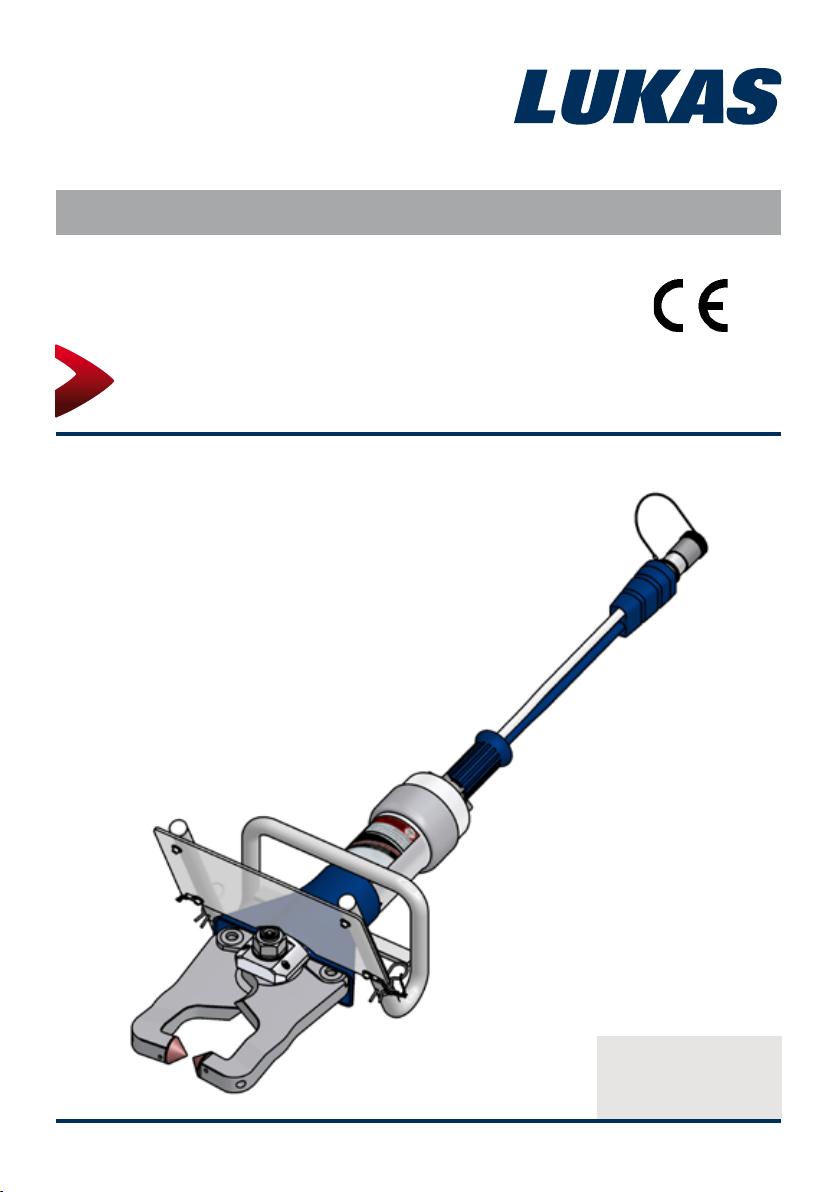
Operating Instructions - Recycling Systems
Concrete Crusher
(Translation of the original operating instructions)
84150150085 GB
Edition 08.2011
replaces 05.2010
Page 2

Contents Page
1. Hazard classes 4
2. Product safety 5
3. Intended use 8
4. Functional description 10
4.1 Description10
4.2 Unit in detail 10
4.3 Circuit diagram 11
4.4 Controlling the operating movements 11
4.5 Hydraulic supply 11
4.6 Hoses 12
4.7 Replaceable tips 12
4.8 Detachable guard 13
5. Connecting the equipment 14
5.1 General points 14
5.2 Coupling Monocouplings 14
5.3 Coupling Quick-disconnect Couplings 16
5.4 MechanicalxingtoabalancerfromtheLUKAS
rangeofaccessories 17
6. Operation 18
6.1 Preparatory measures 18
6.2 Operating the star grip 18
7. Cutting and crushing 19
7.1 Safetyinstructions 19
7.2 Cutting 20
7.3 Crushing 22
8. Dismantling the device / deactivation following operation 23
8.1 Recycling unit 23
8.2 Hydraulic unit 23
8.3 Hoses 23
9. Maintenance and service 24
2
Page 3

10. Repairs 25
10.1 General points 25
10.2 Preventive maintenance 27
10.3 Repairs 31
11. Troubleshooting 40
12. Technical Data 43
12.1 Concrete Crusher 43
12.2 Tighteningtorquesofthepivotbolt 44
12.3 Hydraulicuidrecommendations 44
12.4 Operating and storage temperature ranges 44
13. EC Declarations of Conformity 45
14. Notes 46
3
Page 4

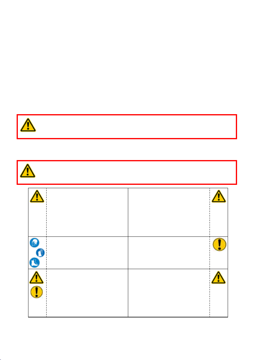
1. Hazard classes
We distinguish between various categories of safety instructions. The table below provides
an overview, using symbols (pictograms) and signal words, of the specic danger and the
possible consequences.
Pictogram
Damage /
injury to
human
device
- NOTE
Key word Denition Consequences
DANGER! Immediate danger
WARNING!
CAUTION!
CAUTION!
Potentially
dangerous situation
Less dangerous
situation
Danger of damage to
device / environment
Advice for
application and other
important / useful
information and
advice
Death or major
injury
Potential death or
major injury
Minor or slight injury
Damage to the
equipment, damage
to the environment,
damage to
surrounding
materials
No injury / damage
to persons /
environment /
equipment
Wear helmet with face protection
Wear protective gloves
Wear safety shoes
Proper recycling
Observe principles of environmental protection
Read and observe operating instructions
4
Page 5
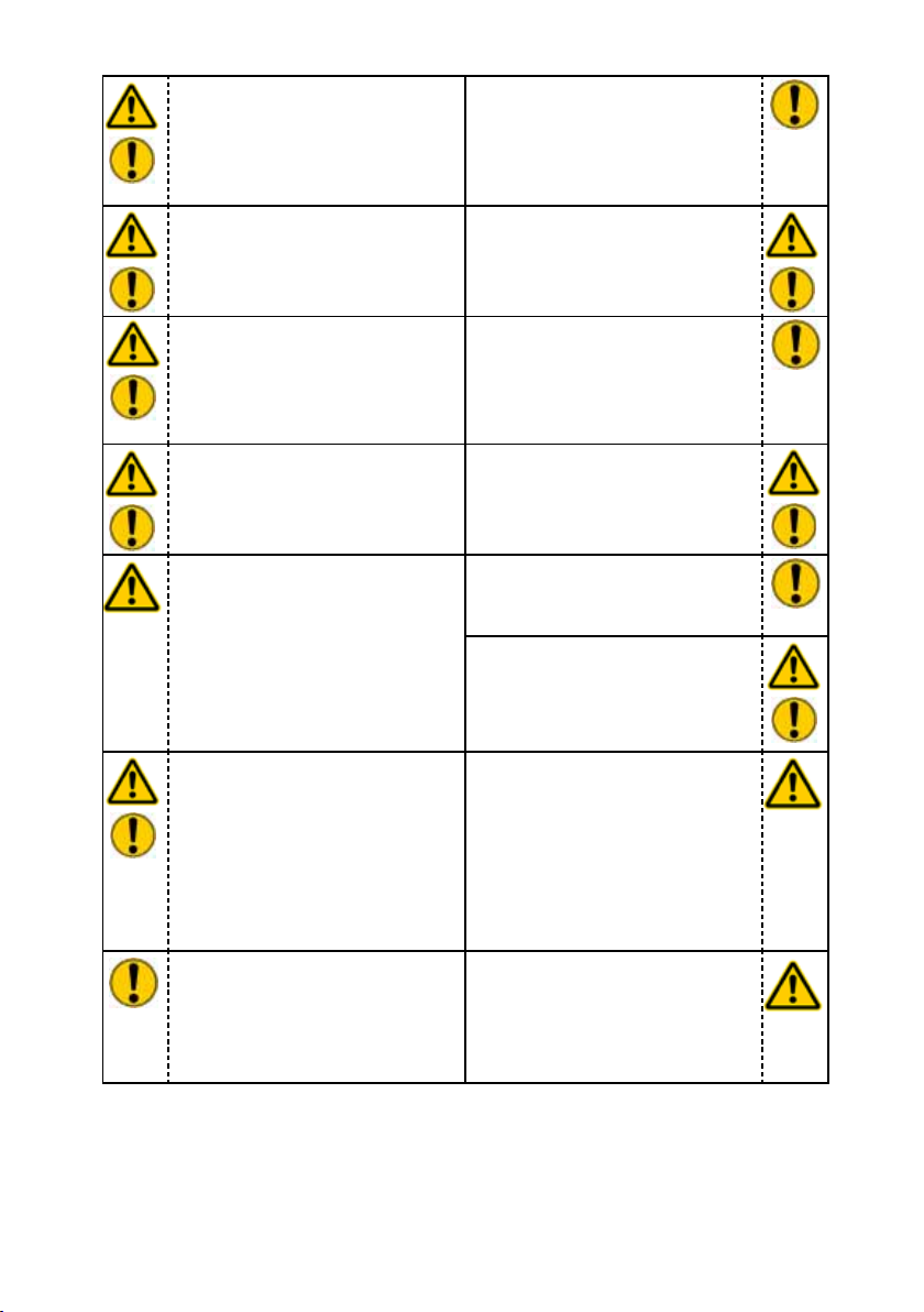
2. Product safety
LUKAS products are developed and manufactured to ensure the best performance and
quality for the intended use.
The safety of the operator is the most important consideration in the design of the product.
Furthermore, the operating instructions are intended to help in using LUKAS products safely.
In addition to the operating instructions, all generally applicable, statutory and other
binding rules for accident prevention and for environmental protection must be heeded and
disseminated.
The device must only be operated by appropriately educated, safety-trained persons, since
otherwise there is a risk of injury.
We would like to point out to all users that they should read the operating instructions carefully
before using the equipment and comply with the instructions there without reservation.
We further recommend that a qualied instructor train you in the use of the product.
WARNING / CAUTION!
The operating instructions for the hoses, the accessories and the connected
devices must also be heeded!
Even if you have already received instructions on how to use the equipment, you should still
read the following safety notes again.
WARNING / CAUTION!
Ensure that the accessories and connected equipment used are suitable for
the maximum operating pressure!
Please ensure that no body
parts or clothing are caught
between the visibly moving
parts (e.g. crusher arms).
Wear protective clothing,
safety helmet with visor, and
protective gloves.
The responsible department
must be informed immediately
of any changes (including to
the operating behaviour)! If
necessary, the device must
be deactivated immediately
and secured!
It is prohibited to work under
loads if the load is lifted
exclusively by hydraulic
equipment. If this work
is absolutely imperative,
additional mechanical
supports must be used.
Inspect the equipment before
and after use for visible
defects or damage.
Check all lines, hoses and
screwed connections for
leaks and externally visible
damage. Rectify any damage
immediately. Squirting
hydraulic uid can result in
injuries and res.
5
Page 6
In the event of malfunctions,
immediately deactivate the
device and secure it. The
malfunction must be repaired
immediately.
Observe all safety and danger
notes on the equipment and
in the operating instructions.
Do not carry out any changes
(additions or conversions) to
the device without obtaining
the prior approval of LUKAS.
All safety instructions and
hazard warnings on the
device must be kept intact
and in a legible condition.
Any method of operation
which impairs safety and/or
stability of the equipment is
prohibited!
Safety devices must never be
deactivated!
Before the equipment is
switched on/started up, and
during its operation, it must
be ensured that nobody is
endangered by the operation
of the equipment.
When working close to live
components and cables,
suitable measures must
be taken to avoid current
transfers or high-voltage
transfers to the equipment.
Prevent electrostatic
discharge, which has the
possible consequence of
spark generation, when
handling the device.
Comply with all specied
dates or dates specied in
the operating instructions
pertaining to regular checks /
inspections of the equipment.
The maximum permitted
operating pressure noted on
the equipment must not be
exceeded.
Only original LUKAS
accessories and spare parts
may be used for repairs.
Make sure that you do not
get caught in the hose loops
and trip when working with or
transporting the device.
Please note that, when
crushing or cutting, tearing
or breaking can cause
falling material, or sudden
removal of such can cause
it to suddenly catapult off:
necessary precautions must
be taken.
Only touch any broken-off
parts or the cut-off parts while
wearing protective gloves,
since the torn / cut edges can
be very sharp.
6
Page 7
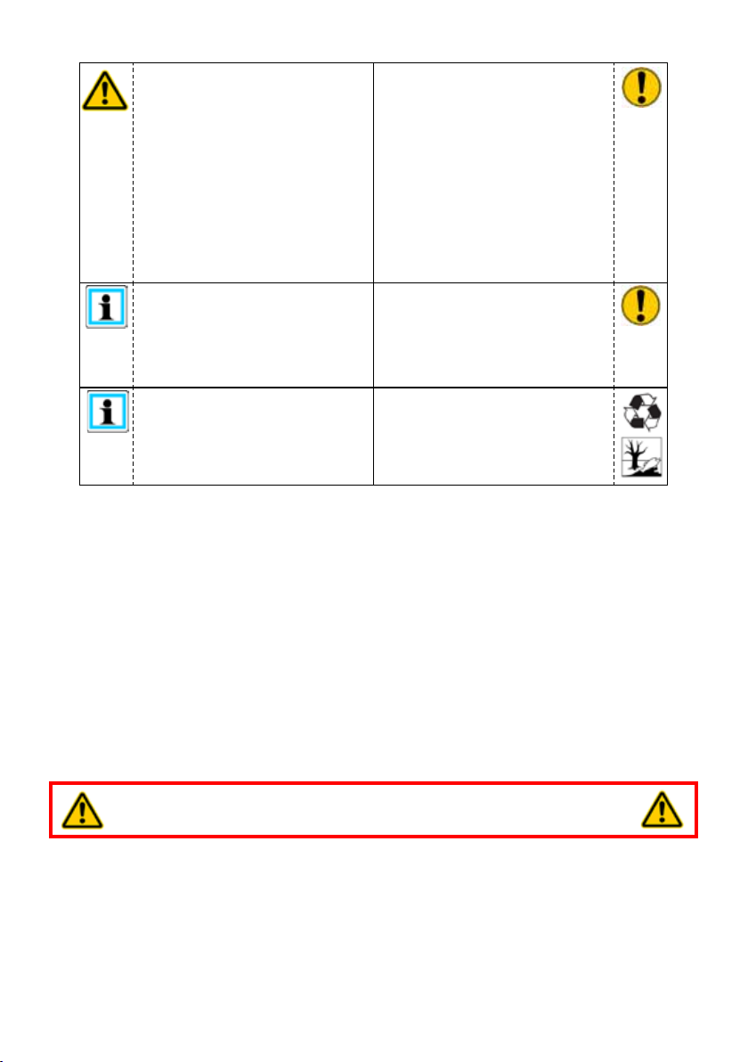
The device is lled with
hydraulic uid. These
hydraulic uids can be
harmful to your health if
swallowed or if their vapours
inhaled. Direct contact with
the skin must be avoided for
the same reason. Please note
also that hydraulic uids can
also have an adverse effect
on biological systems.
Ensure adequate lighting
when you are working.
Always keep these operating
instructions easily accessible
at the location where the
device is used.
The generally applicable, legal and other binding national and international regulations
pertaining to the prevention of accidents and protection of the environment apply and are to
be implemented in addition to the safety information in these operating instructions.
When working with or storing
the equipment, ensure
that the function and the
safety of the equipment
are not impaired by the
effects of extreme external
temperatures and that the
equipment is not damaged in
any way. Please note that the
device can also heat up over
a long period of use.
Before transporting the
equipment, always ensure
that the accessories are
positioned such that they
cannot cause an accident.
Ensure the proper disposal of
all removed parts, left-over oil
and hydraulic uid as well as
packaging materials!
WARNING / CAUTION!
The device is specied exclusively for the purpose described in the operating
instructions (see Chapter “Intended use”). Any use for purposes other than or over and
above this is deemed not to be in accordance with its designated use. The manufacturer/
supplier refuses to accept liability for damage resulting from such misuse. The user bears
sole responsibility for such.
Observance of the operating instructions and compliance with the inspection and maintenance
conditions are part of the Intended use.
Never work when you are overtired or intoxicated!
7
Page 8
3. Intended use
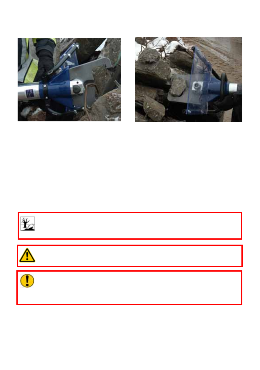
The Concrete Crushers are designed for continuous industrial deployment in demolition work.
The Concrete Crushers can be used, in particular, for the crushing of walls, concrete and
reinforced concrete components and for the cutting up of reinforcement.
You do not need to change tools between crushing and cutting work.
The low-vibration method of working not only reduces the physical load on the body of the user
but also facilitates working in vibration-sensitive areas. An additional advantage of the virtually
zero vibrations is the dust-free demolition work which permits working in an enclosed space.
The noise level is also very low as a result of the purely hydraulic method of operation.
This means that the units can also be used in locations that are sensitive to noise. The main
source of noise is the unit required for the generation of hydraulic pressure.
LUKAS Concrete Crushers can also be used under water at a depth of up to 40m (131ft).
CAUTION!
In this case, you must strictly observe any leaks in order to avoid threats to the
environment.
WARNING / CAUTION!
All objects to be worked on must be secured using stable supports or substructures.
CAUTION!
When cutting with the Concrete Crusher, make sure that you do not cut directly
into the concrete with the blade area. This can lead to increased wear in the
blade area.
The Concrete Crushers must not be used in explosion-risk areas. Sparks can be created
when crushing and cutting from the friction at the crusher arms, and these can ignite explosive
atmospheres.
8
Page 9

The Concrete Crushers need a hydraulic source for their operation and this is connected to
the unit with hoses. A LUKAS hydraulic pump is used as the hydraulic source. The use of other
hydraulic sources is possible, but this will require approval from LUKAS in each individual case.
Because the connection between the unit and the power pack is via hoses, the hydraulic
power packs can be located outside sensitive areas.
You must never use equipment with internal combustion engines in enclosed spaces!
The use of electrical equipment in wet areas is prohibited if it is not specically designed for
this purpose.
LUKAS offers a wide range of the most varied of units for driving the Concrete Crushers.
Contact your authorised LUKAS dealer or LUKAS directly!
WARNING / CAUTION!
The following may not be cut / crushed:
- live cables
- pre-tensioned and hardened parts such as springs, spring steels,
- - pipes / hoses under gas or liquid pressure,
- explosive objects such as gas cartridges
NEVER operate the recycling unit at a higher operating pressure than that stated
in the chapter “Technical data”. A higher setting may cause property damage and/
or injuries.
The Concrete Crushers must not be used in explosion-risk areas. Sparks can be
created when crushing and cutting from the friction at the crusher arms, and these
can ignite explosive atmospheres.
Replacement parts and accessories for the recycling unit can be ordered from your authorised
LUKAS dealer!
9
Page 10
4. Functional description
4.1 Description
The units are designed in such a way that a hydraulically actuated piston symmetrically
opens and closes two identical opposing crusher arms via a mechanical linkage system.
This allows stones or concrete parts to be broken up or reinforcing bars and reinforcing mesh
to be cut.
All Concrete Crushers guarantee full load-holding function when disconnected from the
hydraulic supply (e. g. when unintentionally decoupled; defective hose, and so on). In addition,
the guard can be removed from the unit. In this case, the operator must, however, take other
measures to protect from aking or breaking parts, e.g. by sturdy protective clothing and a
safety helmet with a face-protecting visor
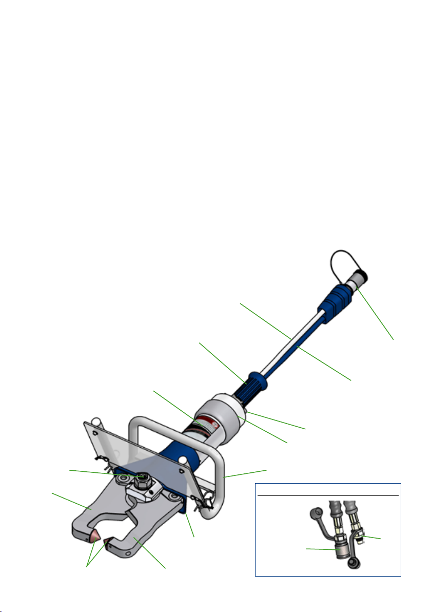
4.2 Unit in detail
1 Star grip
2 Control valve
3 Device body
4 Handle with removable guard
5 Protective sleeve
6 Crusher arm
7 Central pin with self-locking nut
and grease nipple
8 Grip tube
9 Replaceable breaker tips
10 Pressure hose
11 Return hose
12 Quick-disconnect coupling,
male
13 Quick-disconnect coupling,
female
14 Mono-coupling half,
male
3
8
10
14
11
1
2
7
6
5
9
6
10
4
Quick-disconnect coupling system:
12
13
Page 11
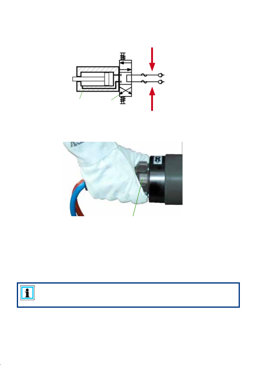
4.3 Circuit diagram
To facilitate understanding of the function, a simplied circuit diagram (hydraulic cylinder of
the Concrete Crusher (A) + hand valve (B)) is shown here.
cutting / crushing /
closing
A
B
opening
4.4 Controlling the operating movements
The piston movement is controlled by the star grip on the attached valve (see illustration).
Star grip
4.5 Hydraulic supply
A LUKAS motor pump or hand pump only may be used to drive the equipment.
If the pump unit is a different make, you must make sure that it complies with LUKAS
specications, otherwise potential dangers may occur which are not the responsibility of
LUKAS. Ensure in particular that the authorised operating pressure for LUKAS equipment
is not exceeded.
NOTE:
Before you use pumps from a different manufacturer, you must contact LUKAS
or an authorised dealer.
11
Page 12
4.6 Hoses
The pump unit and the recycling unit are connected by hoses.
Pleaseobserveallsafetyinstructionsintheseparateoperatinginstructionsforthehoses!
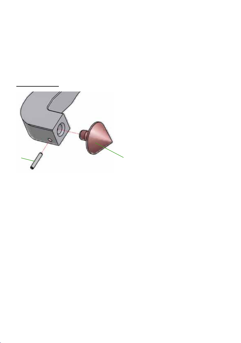
4.7 Replaceable tips
The Concrete Crusher has optional replaceable breaker tips. When they are worn out they can
easily be replaced by new ones.
Replacing the tips:
1. Remove pin “A”
2. Pull out the breaker tips “B” and replace
them.
3. Ret the pin “A”.
A
B
12
Page 13
4.8 Detachable guard
The Concrete Crusher has an optional removable guard. This means that the unit can also be
used in inaccessible locations.
A
1. Remove the split-pin “A”
A
B
2. Pull the guard “B” away upwards.
3. The guard is retted in the reverse sequence. Make sure that the split pins engage
fully.
13
Page 14
5. Connecting the equipment
5.1 General points
There are two short hoses on the side of the equipment: they are connected to the pump unit
via two hoses. All hose assemblies are marked with a colour and have couplings to enable
non-interchangeable connection.
NOTE:
The devices can be equipped with different coupling systems.
They differ only by the article number and not by the designation.
It goes without saying that the coupling systems can also be converted at a
later time.
WARNING / DANGER / CAUTION!
Prior to connecting the devices, ensure that all the components
being used are suitable for the maximum operating pressure
of the pump unit. In case of doubt you must consult LUKAS
directly.
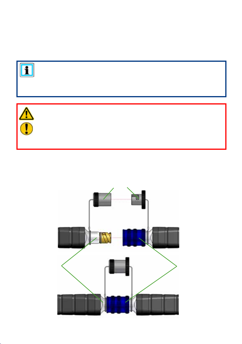
5.2 Coupling Mono-couplings
The device is connected to the hose line to the hydraulic pump using non-interchangeable
monocoupling halves (female and male coupling).
Dust protection caps
Mono-coupling
half (male)
Mono-coupling
half (female)
14
Page 15
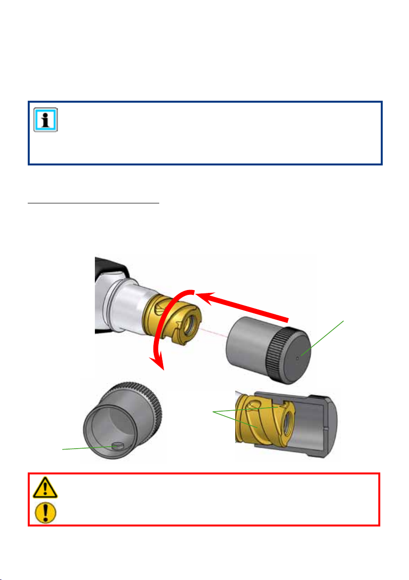
Before coupling, remove dust protection caps, then connect male and female, and turn
the locking sleeve of the female in direction “1” until the locking sleeve locks into place.
The connection is then made and secured. Decoupling is accomplished by turning the
locking sleeve in direction “0”.
The equipment can also be coupled under pressure provided the connected equipment is
not activated.
NOTE:
We recommend coupling the coupling halves in a depressurised state when
working in areas with low ambient temperature and extension hose assemblies /
hose reels are used, otherwise coupling could need very high expenditure of
force.
For dust protection, the supplied dust caps must be reattached.
Using the dust protection caps:
The “A” dust protection caps have two internal pins “B”. The dust protection caps must be
placed on the coupling unions in such a way that the pins are guided into the “C” grooves.
Fasten the screw up to the limit stop to x the dust protection caps on the coupling unions.
A
C
B
WARNING / CAUTION!
The mono-couplings may not be screwed off the hose assemblies and / or the
hose assemblies be mixed up!
15
Page 16

5.3 Coupling Quick-disconnect Couplings
The device is connected to the hose lines to the hydraulic pump using non-interchangeable
quick disconnect coupling halves (female and male coupling).
X
Y
Before coupling, remove the dust caps then pull back and hold the locking sleeve on the
female connector (position X). Plug the male and female connectors together and release the
locking sleeve. Then turn the locking sleeve to position Y. The connection is then made and
secured. Decoupling is done in the reverse sequence.
CAUTION!
Always connect the return hose rst and then the supply hose!
NOTE:
Hoses can be connected only when depressurised.
For dust protection, the supplied dust caps must be reattached.
WARNING / CAUTION!
To some extent the quick-disconnect couplings have special functions and may
therefore not be unscrewed from the hydraulic lines and/or swapped!
16
Page 17

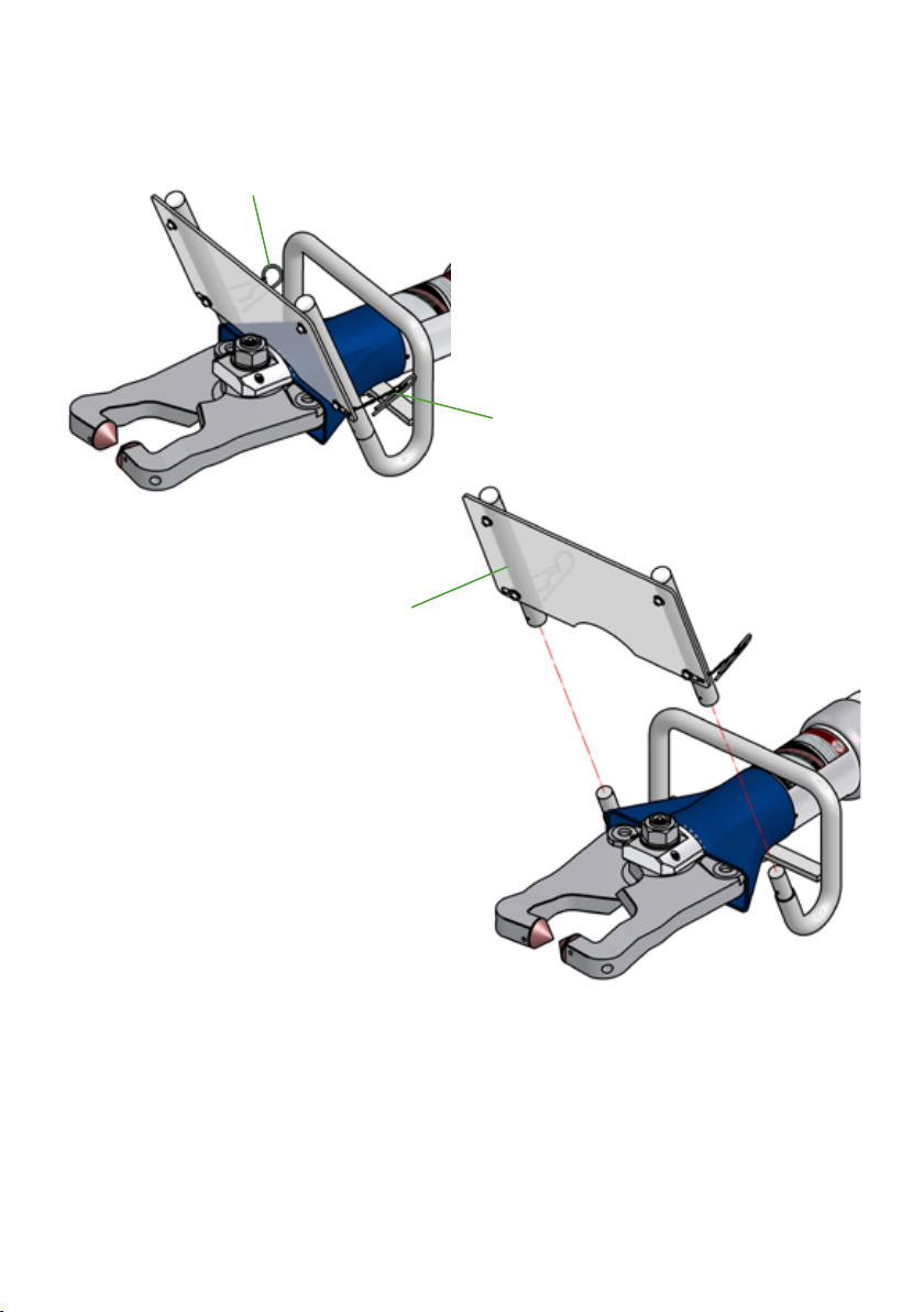
5.4 MechanicalxingtoabalancerfromtheLUKASrangeofacces-
sories
First set the weight of the recycling unit on the green
rotating ring on the back of the balancer (see arrow on
illustration at left); this ensures that the cutting unit later
stays at any height position at a later time.
Fix the balancer using the attached hook (see illustration
at right hand side, Item 1) onto the suspension device
provided (e.g. outrigger hooks)
Then x the recycling unit to the swing bracket (see il-
2
The recycling unit should now be aligned
vertically to the steel rope of the balancer (see
illustration at right).
3
lustration at left hand side).
NOTE:
The unit cannot be clamped in the suspension
device!
This is because the recycling unit is mounted
in a rotating manner in the swing bracket.
The swing bracket is tted with 2 holes in order to balance
out the centre of gravity differences by xing the shackle
(see illustration at left, Item 2) in the 2nd hole.
1
Engaging point:
Pull out locked
Unlock the balancer by pulling out the
pin (see illustration, Item 3) and then
turn anti-clockwise to the second, slightly
higher engaging point and then releasing
to allow it to engage.
Engaging point:
Pull out unlocked
17
Page 18

6. Operation
6.1 Preparatory measures
6.1.1 Initial start-up
Before commissioning and following repairs, the equipment must be de-aerated.
- Connect the equipment to the hydraulic pump (see chapter “Connecting the
equipment”).
- Open / close the crusher arms of the equipment without any load at least twice (see
chapter “Operation of the star grip”).
NOTE:
We recommend that during de-aeration, the attached unit for the hydraulic
supply should stand at a higher level than the body of the recycling unit.
Recommendedprocedureforde-aeratingtherecyclingunit:
1.) open and close fully with the blade arms facing upwards.
2.) open and close fully with the blade arms facing downwards
3.) open and close fully with the blade arms facing upwards.
4.) open and close fully with the blade arms facing downwards
6.1.2 Inspection of the pump unit
See the separate operating instructions for the relevant unit (or the handpump).
NOTE:
Before each start-up of the hydraulic unit you have to make sure that the
actuating valves are set to depressurized circulation.
Before coupling the quick-disconnect couplings, the actuating valves of the
hydraulic unit are set to depressurized circulation.
6.2 Operating the star grip
Open device ( ):
Turn the star grip in a clockwise direction (in the direction of the
relevant symbol) and keep in this position.
Close device ( ):
Turn the star grip in an counterclockwise direction (in the
direction of the relevant symbol) and keep in this position.
“Dead-man’s” function:
Following release, the star grip automatically returns to the
central position, fully guaranteeing load-retention.
18
Page 19

7. Cutting and crushing
7.1 Safetyinstructions
Before starting work, the object to be processed must be stabilised and secured in its
position. This in ensured by adequate supports and / or props.
Comply with the safety regulations in force in the country of use.
The units must not be used in explosion-risk areas.
Wear the following when working with recycling unit:
- Protective clothing and safety shoes,
- Safety helmet with visor or goggles
- Protective gloves
- and, if necessary, hearing protection
Before operating the recycling unit, you should ensure that no participants or bystanders
are at risk from the movements of the unit or from ying fragments! Furthermore, avoid
unnecessary damage caused by the recycling unit / ying fragments to other objects not
being processed.
Reaching between the crusher arms is strictly forbidden!
WARNING / CAUTION!
When working, sections of the object being processed may ake off or y away
as a result of the exceptional forces involved in the recycling units. Those not
involved in the rescue operation should therefore keep at a distance appropriate
to the situation.
19
Page 20

7.2 Cutting
The blades must be positioned at a 90° angle to the object to be cut.
15°
15°
12
90°
9
RIGHT
6
Higher cutting capacities can be achieved by cutting as close as possible to the crusher
arm’s pivot point.
RIGHT
3
20
WRONG
WRONG
Page 21

Cutting area
Crusher arm
pivot point
CAUTION!
Avoid cutting particularly high-strength parts (e.g. spring steel or rollers),
because this almost always causes damage to the recycling unit!
21
Page 22

7.3 Crushing
The crusher arms must be applied at right angles to the material to be crushed.
90°
WRONG
RIGHT
When the two crusher arms are moved together, the tip penetrates the concrete component
and this leads to the fracture of this part.
If the concrete component does not break by the time the crusher arm internal faces are in
contact with the goods to be crushed, you need to open the crusher arms again and apply
them again.
To avoid excessive wear, make sure that the crushing is not carried out with the cutting area.
Cutting area
Crusher arm
pivot point
22
Page 23

8. Dismantling the equipment / deactivation following
operation
8.1 Recycling unit
Once work has been completed, the crusher arms must be closed so that there is a tip
distance of just a few mm. This relieves the hydraulic and mechanical stresses on the device.
NOTE:
Never store the Concrete Crusher with fully-closed blade arms! The complete
closure of the crusher arms can cause hydraulic and mechanical stress to build
up again.
Free the recycling unit of any stubborn dirt which may have become attached during use.
If the equipment is to be stored for a longer period of time, the exterior must be cleaned
completely and the mechanical moving parts lubricated.
Avoid storing the recycling unit in a damp environment.
Please also observe the separate operating instructions for the hoses.
8.2 Hydraulic unit
Upon completion of work, the unit must be deactivated.
8.3 Hoses
First of all, decouple the pressure hose then the return hose as described in chapter
“Connecting the equipment”.
Ensure that you put the dust protection caps back on to the couplings.
23
Page 24

9. Care and Maintenance
The equipment is subject to very high mechanical stresses. A visual inspection must be
carried out after every use: however, at least one visual inspection must be carried out every
six months. These inspections enable the early detection of wear and tear, which means that
breakages can be prevented by punctual replacement of these wearing parts. Also regularly
check the torque of the pivot bolt. (Torque M
Every 500 operating hours a crack test of the crusher arms is also essential. Therefore a
special crack testing kit is available.
Every 500 operating hours or if there is any doubt regarding the safety or reliability of the
equipment, a function test must also be performed. (Please also observe the relevant valid
national and international regulations pertaining to service intervals of recycling units).
CAUTION!
Clean the device before checking for contamination!
When cleaning the equipment, take care not to use any cleaning agent that has
a pH value outside the range 5 - 8!
WARNING / CAUTION!
To perform maintenance and repairs, workshop and personal safety equipment
appropriate for the work is an absolute requirement.
Inspections to be carried out:
Visual inspection
Concrete Crusher
• Opening width of the crusher arms at the tips (see chapter “Technical data”),
• General tightness (no leaks)
• Operability of the star grip,
• Handle present and secure,
• Labels complete and legible,
• Covers in perfect condition,
•
Check of the torque of the pivot bolt (torque MA see “Technical Data”),
• Couplings must be easy to couple,
• Dust protection caps must be present.
• Dirt in the protective sleeve (this dirt must be removed immediately!)
• Check of the protective equipment on / around the recycling equipment, especially the
protective cover for the moving parts (this must be free of cracks!).
see “Technical Data”)
A
Crusher arms
• Crusher arms free of cracks and without any chipped spots or deformations on the cutting
surfaces,
• Cutting surfaces pass over each other without making contact,
• Bolts and retaining rings of the blade arms must be present and in correct working order,
• Tips must be present, clean and with an edge, without cracks.
24
Page 25

Hoses
• Visual check for visible damage
• Check for leaks
Functional test
• perfect opening and closing when star grip activated,
• no suspicious noises.
• no further movement of the crusher arms when valve actuation interrupted during the
process (“dead-man’s” function)
10. Repairs
10.1 General points
Service work may only be performed by the device manufacturer or by personnel trained by
the device manufacturer and authorised LUKAS dealers.
Only LUKAS spare parts may be used to replace all components (see spare parts list) since
special tools, assembly instructions, safety aspects, inspections might have to be taken into
account (see also chapter “Care and Maintenance”).
During the assembly work, pay particular attention to the cleanliness of all components
as dirt can damage the recycling equipment!
WARNING / CAUTION!
Protective clothing must always be worn when repairs are being carried out,
since parts of the units can also be pressurised in an idle state.
CAUTION!
Because LUKAS recycling devices are designed for the highest performance,
only components may be replaced that are listed in the replacement parts lists
for the corresponding device.
Other components on the equipment may only be replaced if:
- you have taken part in appropriate LUKAS service training,
- you have the explicit permission of the LUKAS Service department (After
request, check for the granting of permission. A check is necessary in each
individual case).
NOTE:
Always send the warranty registration card back to LUKAS Hydraulik GmbH.
Only then are you entitled to the extended guarantee.
NOTE:
You must always contact LUKAS or an authorised dealer before using third party
couplings.
25
Page 26

NOTE when using the quick-disconnect coupling system:
Over-pressuresafetydeviceoftherecyclingunit
(modelwithyellowcouplingnippleonthereturnhose)
Pressure can build up in the device as a result of temperature rises if the device's
short hoses are not connected to a power pack. Hence, the return hose of the
equipment is equipped with a safety coupling (quick-disconnect coupling male,
yellow). Undesired overpressure (approx. 1.5 MPa) is automatically reduced via
this male coupling: hydraulic uid leaks out.
Should hydraulic uid leaks on the coupling male be more frequent, please
contact your dealer or LUKAS itself.
If couplings from a different company are used which do not have this function,
the overpressure protection in the valve of the rescue equipment may respond.
Hydraulic uid leaks out in the area of the star grip. Following the reduction in
pressure, the valve is once again tight.
Should the valve leak permanently, please immediately contact your dealer or
LUKAS itself.
CAUTION!
When cleaning the equipment, take care not to use any cleaning agent that has
a pH value outside the range 5 - 8!
26
Page 27

10.2 Preventive maintenance
10.2.1 Care instructions
The exterior of the equipment must be cleaned from time to time in order to protect it from
external corrosion. Oil must be applied to the metallic surfaces.
10.2.2 Routine checks
Regularly check the torque of the pivot bolt.
For torques, see Chapter “Technical Data”.
Check the cutting faces and repair if possible. Refer to the Chapter “Regrinding the Crusher Arms”.
Once a day when the unit is being used, the pivot pin should be greased with LUKAS special
grease.
A
B
Grease the cutting unit with a grease gun as shown
on the right using LUKAS special grease.
The grease nipple (item A) is located immediately
on the central pivot pin on the side with the locknut
(item B).
Excess grease that remains on the grease nipple
after greasing (see left) should be removed and
disposed of properly.
CAUTION!
Particularly when working with the crusher arms pointing upwards, make sure that
no larger broken off pieces make their way under the exible protective sleeve into
the mechanical section of the unit. The moving parts of the unit can be blocked and
even destroyed by this.
The unit must therefore be checked for dirt contamination and foreign bodies in the
mechanical section and cleaned if necessary after each time it is used in this way.
27
Page 28

Unscrew the hand grip and pull back the protective sleeve as shown in the illustration below.
Remove contamination and swarf from the mechanical section of the unit (as shown in the
illustration below) and blow out carefully with compressed air.
If the sections of the protective sleeve that seal against the crusher arms are clearly worn or
torn, you should replace the entire sleeve.
10.2.3 Main checks
The mechanical transmission elements on the device are subject to very high mechanical
loading and must therefore be checked at least every 500 operating hours. These inspections
enable the early detection of wear and tear, which means that breakages can be prevented
by punctual replacement of these wearing parts.
Parts that are undamaged can be reassembled after careful greasing with LUKAS special
grease.
Parts showing slight wear (scuff marks) can be repaired by polishing and can be retted after
greasing as required.
More severe signs of wear require replacement of the damaged parts (in pairs).
After these intervals a crack test of the crusher arms is also essential. Therefore a special
crack testing kit is available.
Clean the outside of the device from time to time and wipe it with oil to prevent corrosion.
28
Page 29

10.2.4 Function and load test
Perform a stress test if there is doubt about safety or reliability.
For the load test, the recycling unit must be surrounded by a sturdy screen. The screen must
be capable of protecting all involved and uninvolved persons from mechanical failure of the
unit during the test. Mechanical failure includes e.g. the fracture of the crusher arm or the
failure of the hose.
In the load test the maximum operating pressure is applied to the Concrete Crusher. The
crusher arms must then be applied by the tips against a min. 30 mm thick block of aluminium.
Load testing:
Thefollowingcomponentswillberequiredfortheloadtest:
- a screen. This must be capable of protecting all involved and uninvolved persons
from mechanical failure of the unit during the test. Mechanical failure includes e.g. the
fracture of the crusher arm or the failure of the hose.
- a test pressure gauge for connection to the hydraulic lines (pressure range at least up
to the maximum operating pressure of the hydraulic source)
- a block of aluminium at least 50 x 50 x 30 mm in size
- an appropriate crack testing kit
Carrying out the load test:
1. Connect the test pressure gauge between the Concrete Crusher and the hose to the
hydraulic source. The pressure gauge must be capable of measuring the pressure in
the pressure line
2. Place the unit under the screen so that you can operate the unit and read the value on
the pressure gauge. In addition, it must be screened so that nobody will be at risk if the
unit suffers mechanical failure.
3. Start the hydraulic supply of the recycling unit.
4. Open the unit by approx. 60 mm.
5. Place the block of aluminium between the tips of the crusher arms.
6. Now you can start the test. Close the crusher arms so that the tips press into the
aluminium block. Keep holding the star grip on the unit in position to close the unit.
7. After approx. 30 seconds, read off the value on the test pressure gauge and release
the star grip. The value read off on the test pressure gauge must correspond to the
maximum operating pressure of the hydraulic source. A deviation of 10 % is acceptable.
8. Open the crusher arms again so that you can remove the block of aluminium.
9. Then carry out a crack test on the crusher arms.
If the unit has passed these tests, then it is in order.
29
Page 30

10.2.5 Replacingthehydraulicuid
- Change the hydraulic uid after approximately 500 operating hours, and every two years
at the latest.
- It must always be changed whenever the hydraulic uid for the accompanying pump
(motor / hand pump) is changed. This prevents the fresh uid from being contaminated by
the used uid from the recycling unit.
Procedure:
1. Close crusher arms (until the tips are almost touching).
2. Change the hydraulic uid of the pump. Please observe the separate operating instructions
for the pump being used!
3. Screw off the return hose on the pump:
- when the hose connection is via mono-coupling to the pump:
remove the cover from the mono-coupling (male).
completely unscrew the connection nut of the blue return hose on the mono-coupling
(male).
- when the hose connection is via quick-connect-coupling to the pump:
Release the union nut on the hose completely from the plug connector nipple on the
blue return ow line.
4. Put the return hose into a separate collecting basin for the hydraulic uid still in the
equipment.
5. Slowly open the crusher arms on the tool (the pump must be working during this time).
The old hydraulic uid from the ring space side runs via the return hose into the separate
collecting basin, and must be disposed of in the same manner as the old hydraulic uid
from the pump.
6. Switch the pump off (motor pump) / no longer activate it (e.g. hand pump).
7. Reconnect the return hose to the pump:
- when the hose connection is via mono-coupling to the pump:
screw the connection nut of the blue return hose back onto the mono-coupling (male).
(Please observe the necessary torque of M
Pull back the cover on the couplings as far as the limit stop.
- when the hose connection is via quick-connect-coupling to the pump:
Screw the union nut on the hose on the plug connector nipple on the blue return ow line.
(Please observe the necessary torque of M
8. De-aerate the recycling unit as described in the chapter “Preparatory measures”.
= 40 Nm!)
A
= 35 Nm!)
A
30
Page 31

10.3 Repairs
10.3.1 Repairs to the unit
(without replacement of guard, hose or coupling )
Components to be
replaced
Guard 1. - 5. and 14.
Handle 1. - 6. and 14.
Pivot bolt 1., 2., 8. and 14.
Crusher arms 1. - 10. and 14.
Tips 1., 11. and 14.
Protective sleeve 1. - 10. and 12. - 14.
Procedure:
1. First of all, carefully clean the rescue equipment.
2. Next, close the blade arms so that the tips are almost touching.
NOTE:
The crusher arm bolts are only accessible when the crusher arms are almost
touching!
A
Required work
steps
3. Remove the split pin “A”
31
A
Page 32

B
4. Pull the guard “B” away upwards.
5. Release screws “C” and remove them together with the washers “D” and xing
elements “E” with the associated split pins “A”. You can now replace the guard “F” and
the posts “G”. The plugs “H” can be levered out using a screwdriver, for example.
D
C
D D
E
F
A
D
G
32
H
G
E
A
Page 33

K
J
7. Push the protective sleeve “L” in the
depicted direction until the securing
bolts “M” are easily accessible.
N
O
6. Remove the screws “J”.
Then, the handle “K” can be removed in
the direction of the connecting hoses of
the device.
M
L
M
P
9. Remove the safety rings “Q” and
push out the bolt “R”.
8. Remove the locknuts “N” and the washer
“O” and push out the pivot pin “P”.
R
Q
33
Page 34

10. Now, you can remove the crusher arm
“S” and slide plates “T”. The seals “U”
on the crusher arms can be removed
U
and replaced.
S
U
11. By removing the pins “V”, you can
also replace the tips “W”.
X
S
T
V
W
12. Fold in the lever elements “X”.
X
13. Finally, remove the protective sleeve
“L” from the equipment as shown.
L
14. In order to assemble the new parts, points 2 -13 should be carried out in reverse order.
34
Page 35

CAUTION!
Don’t forget to apply LUKAS special grease to all sliding surfaces.
CAUTION!
The nut of the pivot bolt and the pivot bolt itself are matched by a special procedure,
therefore they must only be changed as a set by using a new set! Because of the
special procedure, any unscrewing of the nut while working will be minimised and a
resulting crusher arm fracture will be prevented.
The nuts can be unscrewed and tightened up to 10 times without affecting the
service performance!
35
Page 36

10.3.2 Replacing or tightening the hoses
Hose connection on the pressure and/or return line is leaking or hoses are defective. Tighten
the hoses on the control valve.
(Please note! Observe torque of M
NOTE when using mono-couplings:
If you want to change the hoses, you must rst dismantle the mono-couplings.
CAUTION (when using the mono-coupling system)!
Take care that the port ‘T’ of the recycling unit is always connected to the port ‘T’
of the mono-coupling.
CAUTION (when using the quick-disconnect coupling system)!
The return hose, which is screwed onto port “T” of the recycling unit, must always
be tted with a male quick-disconnect coupling.
However the supplying hose line must be tted with a female quick-disconnect
coupling.
Procedure:
1. Loosen the 2 B screws in the handle sleeve
with quick-disconnect protective sleeves C
(hexagon socket)
= 40 Nm!)
A
A
BC
2. Remove handle sleeve A and tighten
screwed connection. If necessary, renew
seals.
D
EF
3. Dismantle hose D and sealing ring E. (This
point is omitted if the hoses are just being
tightened!)
4. Screw the hose with sealing ring back on.
Please ensure that the insulating washer F
is on and correctly assembled.
dismantle
assemble
5. Tighten the hose connection on the control valve. (Please note! Observe the
necessary torque of M
= 40 Nm!)
A
6. Then replace handle sleeve, protective sleeves and screws, tighten (Torque:5 Nm) and
secure it with thread-locking compound (e. g. LOCTITE 243).
36
Page 37

10.3.3 Regrinding the crusher arms
Only burrs may be removed and smoothed out!
Chips or deep grooves cannot be ground away. The crusher arms must be replaced in these
cases.
CAUTION!
Only grind in the grinding area (see illustration)!
The sliding faces, in particular, must not be reground!
Pivot point
Crusher arm
Slide surface
plane
Direction of
movement
Crusher arm
Grinding area
Tools required: 1. Clamping device (e.g. vice) with jaw protection in order not to
damage the crusher arms.
2. Grinder (e.g. angle grinder or belt grinder) with abrasive having
a grain size of 80.
Procedure:
1. Clamp the crusher arm securely into the clamping device so that it cannot move, but with
the area to be ground exposed.
2. Carefully grind the burr away evenly until you reach the sliding surface level. (see
illustration).
Slide surface plane
In addition, when grinding, you must make sure that the rake of the cutting surface in the
direction of the crusher arm movement is not changed. Check the rake and smoothness
of the ground surface, using a suitable measuring tool.
CAUTION!
If you have not maintained the smoothness or rake, the proper operation of the
blade is no longer guaranteed and the crusher arms must be replaced.
37
Page 38

10.3.4 Mono-couplings
The mono-couplings on the connection hoses on the equipment must be replaced if:
- there is external damage
- the locking mechanism does not work
- hydraulic uid continues to leak in the coupled/uncoupled state.
WARNING / CAUTION!
Never repair couplings: they must be replaced by original LUKAS parts!
During assembly, tighten the union nuts on the hose line to a torque of MA = 40 Nm.
Procedure:
1. Remove the cover from the couplings.
2. Loosen the connection nuts of the hose assembly and remove the coupling.
3. Position the new coupling and tighten the union nuts on the hose lines to a
torque of M
= 40 Nm and push the cover back over the couplings.
A
CAUTION!
Take care that the port ‘T’ of the rescue tool is always connected to the port ‘T’
of the mono-coupling.
38
Page 39

10.3.4 Quick-disconnect coupling
The quick-disconnect-couplings must be replaced if:
- there is external damage
- the locking mechanism does not work
- hydraulic uid continues to leak in the coupled/uncoupled state.
WARNING / CAUTION!
Never repair couplings: they must be replaced by original LUKAS parts!
During assembly, tighten the union nuts on the hose line to a torque of M
= 35 Nm.
A
Procedure:
1. Loosen the union nuts on the hose line and remove the coupling.
2.
Position the new coupling and tighten the union nuts on the hose lines to a
torque of M
= 35 Nm.
A
CAUTION!
The return hose, which is screwed onto the port “T” of the recycling unit, must
always be tted with a male quick-disconnect coupling.
However the supplying hose line must be tted with a female quick-disconnect
coupling.
10.3.5 Control valve
Should the control valve be deformed so severely that the star grip no longer functions
correctly, the valve must be replaced in its entirety.
Have repairs carried out by an authorised dealer, by personnel specially trained by LUKAS,
or by LUKAS customer service only.
10.3.6 Labels
All damaged and/or illegible labels (safety notices, type plate etc.) must be replaced.
Procedure:
1. Remove damaged and/or illegible labels.
2. Clean surfaces with industrial alcohol.
3. Attach new labels.
Ensure that you attach the labels in the correct position. If this is no longer known, you should
ask your authorised LUKAS dealer or contact LUKAS directly.
39
Page 40

11. Troubleshooting
Trouble Check Cause Solution
Crusher arms move
slowly or jerkily when
activated
Device doesn’t
perform at its given
power
Following release,
the star grip doesn’t
return to the central
position
With mono-couplingsystem: hose
assembly cannot be
coupled
With monocoupling-system:
It is frequently not
possible to couple
hose assemblies
With quickdisconnect-couplingsystem: hose
assembly cannot be
coupled
Hydraulic uid leak
at the hoses or the
connections
Are the hoses
connected
properly?
Does the pump
unit work?
Check the
hydraulic uid level
in the supplying
pump
Cover damaged
or star grip hard to
move?
Check the
viscosity grade
and application
temperature of
the hydraulic uid
used.
Is the pump
working?
Are the hoses
defective?
Air in the hydraulic
system
Insufcient
hydraulic uid in
the pump
Damage to the
torsion spring for
reset
Soiled valve or
star grip
Defective valve
Other mechanical
damage (e. g. star
grip)
Pressure too high
(e.g. caused by
too-high ambient
temperature)
Coupling defective Coupling must be
Hydraulic uid
not suited to
the application
situation
Coupling defective Coupling must be
Pressurised Relieve pump
Coupling defective Coupling must be
Leakage, possible
damage
De-aerate pump
system
Top up hydraulic uid,
de-aerate
Repair of fault by
authorised dealer,
specially trained
LUKAS staff or
directly by LUKAS
Set hydraulic pump
to pressureless
circulation
replaced immediately
Hydraulic uid
must be replaced
(see chapter
“Recommended
hydraulic uids”)
replaced immediately
replaced immediately
Replace hoses.
40
Page 41

Trouble Check Cause Solution
Damage on the
surface of the
hydraulic hoses
Hydraulic uid leaks
on the piston rod
Leak on the handhold Does the pressure
set on the pump
comply with
the maximum
permissible
pressure on the
recycling unit?
Hoses in handhold
loose?
Is the return
hose connected
correctly?
Especially when
using quickdisconnect couplings:
Leak on the handhold
Especially when
using monocouplings: Leak on
the handhold
With mono-couplingsystem: Leak in the
couplings
Is the return
hose connected
correctly?
Check the
connections of the
hoses
Is the coupling
damaged?
Mechanical
damage or contact
with aggressive
agents
Defective rod seal Repair of fault by
Damage to the
piston
Pressure drop in
recycling unit
Hoses in handhold
not tightened
Return hose is not
coupled correctly
or not connected.
Return hose is not
coupled correctly
or not connected.
Hose connection
to the couplings
interchanged
Return line
constricted
Coupling defective Coupling must be
Replace hoses.
authorised dealer,
specially trained
LUKAS staff or
directly by LUKAS
After pressure
release, there is no
more leakage.
Should, however,
there be a further
leak on the handhold,
immediately
deactivate the
recycling unit and
contact an authorised
dealer or LUKAS
itself.
Tighten hoses.
Re-connect the return
hose and secure it.
Re-connect the return
hose and secure it.
Reconnect the hoses
to the coupling in the
correct way
Disconnect the
return line from the
coupling, clean it and
reconnect it.
replaced immediately
41
Page 42

Trouble Check Cause Solution
With quickdisconnect-couplingsystem: Leak in the
couplings
If it isn’t possible to rectify the malfunctions, inform an authorised LUKAS dealer or the
LUKAS customer service department immediately!
The address of the LUKAS Customer Service Department is:
Is the coupling
damaged?
Is the leak only on
the male coupling
(in uncoupled
status)?
Coupling defective Coupling must be
replaced immediately
Safety valve
responded
After pressure
release, there is no
more leakage.
LUKAS
Weinstrasse 39, D-91058 Erlangen
Phone: (+49) 09131 / 698 - 348
Fax.: (+49) 09131 / 698 - 353
Hydraulik GmbH
42
Page 43

12. Technical data
Because all values are subject to tolerances, there may be small differences between the
data for your device and the data in the following tables!
The values may also differ because of reading inaccuracies and/or tolerances in the
measuring equipment used.
NOTE:
The following tables contain only the technical data required for standard
acceptance.
Additional data concerning your unit can be obtained from LUKAS on request.
12.1 Concrete Crusher
Type LSI531CC
Ref. No. 112160000 172160000
Connection / control system 4/3 way valve
Dimensions l x w x h
(w/o connection hoses)
Max. opening
Min. opening
Weightincl.hydraulicuid
Max. operating pressure
Required volume of
hydraulicuid**
Coupling system
[mm] 805 x 350 x 325
[in.] 31.69x13.78x12.80
[mm] 310
[in.] 12.20
[mm] 9
[in.] 0.35
[kg] 23,9
[lbs.] 52.7
[Mpa] * 50
[psi.] 7,252
[l] 0,15
[gal.-US] 0.04
Quick-disconnect-
coupling
Monocoupling
* 1 MPa = 10 bar
43
Page 44

12.2 Tightening torques of the pivot bolt
Type LSI 531 CC
Pivot bolt M 27 x 1,5
Wrench size
Torque
[mm] 41
[in.] 1.61
[Nm] 130 +10
[lbf.in.] 1,151+89
12.3 Hydraulicuidrecommendations
Mineral oil DIN ISO 6743-4 for LUKAS hydraulic equipment and others
Oil temperature range Oil code Viscosity rating Remarks
A -20 .... +55°C HM 10 VG 10
Oil temperature range Oil code Viscosity rating Remarks
A -4.0 .... +131°F HM 10 VG 10
recommended viscosity range: 10...200 mm²/s (10…200cSt.)
Supplied with HM 10 DIN ISO 6743-4.
CAUTION!
Before using hydraulic uids which do not conform to the above-mentioned
specications and/or are not purchased from LUKAS, you must contact LUKAS!
12.4 Operating and storage temperature ranges
Operating temperature [°C] / [°F] -20 … +55 -4 … +131
Ambient temperature
(device in operation)
Storagetemperature
(device not in operation)
[°C] / [°F] -25 … +45 -13 … +113
[°C] / [°F] -30 … +60 -22 … +140
44
Page 45

13. EC Declarations of conformity
45
Page 46

14. Notes
46
Page 47

47
Page 48

Please dispose all packaging materials and
dismantled parts properly.
LUKAS
A unit of the IDEX Corporation
Hydraulik GmbH
Weinstrasse 39, D-91058 Erlangen
Phone: (+49) 0 91 31 / 698 - 0
Fax.: (+49) 0 91 31 / 698 - 394
e-mail: lukas.info@idexcorp.com
www.lukas.com
Made in GERMANY
© Copyright 2009 LUKAS Hydraulik GmbHConcrete_Crusher_BA_GB_84150150085_0811.indd
Subject to revision
 Loading...