

Page 1

DEFINITY®Enterprise Communications
Server and System 75 and System 85
Terminals and Adjuncts Reference
555-015-201
Comcode 108603994
Issue 11
December 1999
Page 2

Copyright 1999, Lucent Technologies
All Rights Reserved
Printed in USA
Notice
Every effort was made to ensure that the information in this book was
complete and accurate at the time of printing. However, information is
subject to change.
Your Responsibility for Your System’s Security
Toll fraud is the unauthorized use of your telecommunications system by
an unauthorized party, for example, persons other than your company’s
employees, agents, subcontractors, or persons working on your
company’s behalf. Note that there may be a risk of toll fraud associated
with your telecommunications system and, if toll fraud occurs, it can result
in substantial additional charges for your telecommunications services.
You and your system manager are responsible for the security of your
system, such as programming and configuring your equipment to prevent
unauthorized use. The system manager is also responsible for reading all
installation, instruction, and system administration documents provided
with this product in order to fully understand the features that can
introduce risk of toll fraud and the steps that can be taken to reduce that
risk. Lucent Technologies does not warrant that this product is immune
from or will prevent unauthorized use of common-carrier
telecommunication services or facilities accessed through or connected to
it. Lucent Technologies will not be responsible for any charges that result
from such unauthorized use.
Federal Communications Commission Statement
Part 15: Class A Statement.
found to comply with the limits for a Class A digital device, pursuant to
Part 15 of the FCC Rules. These limits are designed to provide
reasonable protection against harmful interference when the equipment is
operated in a commercial environment. This equipment generates, uses,
and can radiate radio-frequency energy and, if not installed and used in
accordance with the instructions, may cause harmful interference to radio
communications. Operation of this equipment in a residential area is likely
to cause harmful interference, in which case the user will be required to
correct the interference at his own expense.
Registration Number.
accordance with Part 68 of the FCC Rules. It is identified by FCC
registration number xxx.
Allowing this equipment to be operated in a manner that does not provide
proper answer-supervision signaling is in violation of Part 68 Rules. This
equipment returns answer-supervision signals to the public switched
network when:
• Answered by the called station
• Answered by the attendant
• Routed to a recorded announcement that can be
administered by the CPE user
This equipment returns answer-supervision signals on all DID calls
forwarded back to the public switched telephone network. Permissible
exceptions are:
• A call is unanswered
• A busy tone is received
A reorder tone is received
Canadian Department of Communications (DOC)
Interference Information
This digital apparatus does not exceed the Class A limits for radio noise
emissions set out in the radio interference regulations of the Canadian
Department of Communications.
Le Présent Appareil Nomérique n’émet pas de bruits radioélectriques
dépassant les limites applicables aux appareils numériques de la class A
préscrites dans le reglement sur le brouillage radioélectrique édicté par le
ministére des Communications du Canada.
Trademarks
5ESS, ACCUNET, AUDIX, CALLMASTER, CentreVu, DEFINITY,
DIMENSION, MERLIN, PassageWay, SPOKES MAN, TERRA NOVA, and
TransTalk are registered trademarks of Lucent Technologies.
CARBON COPY Plus is a trademark of Microcom Systems Inc.
E78 PLUS, CROSSTALK, and VT are registered trademarks of Digital
Equipment Corporation.
This equipment has been tested and
Part 68: Network
This equipment is registered with the FCC in
Part 68: Answer-Supervision Signaling.
HAYES is a registered trademark of Hayes Microcomputer Products, Inc.
HYPERACCESS is a registered trademark of Hilgraeve Corporation.
IBM is a registered trademark of International Business Machines
Corporation.
Micro Channel is a trademark of International Business Machines
Corporation.
PROCOMM PLUS is a registered trademark of Datastrom Technologies.
ProLogix and TransTalk are trademarks of Lucent Technologies.
RELAY GOLD is a registered trademark of Microcom Systems, Inc.
SideKick is a registered trademark of Starfish Software, Inc.
SMARTMODEM 2400 and SMARTCOM are trademarks of Hayes
Microcomputer Products, Inc.
Ordering Information
Call: Lucent Technologies BCS Publications Center
Write: Lucent Technologies BCS Publications Center
Order: Document No. 555-015-201
You can be placed on a standing order list for this and other documents
you may need. Standing order will enable you to automatically receive
updated versions of individual documents or document sets, billed to
account information that you provide. For more information on standing
orders, or to be put on a list to receive future issues of this document,
contact the Lucent Technologies BCS Publications Center.
For more information about Lucent Technologies documents, refer to the
Business Communications Systems Publications Catalog
Voice 1 800 457-1235 International Voice 317 322-6791
Fax 1 800 457-1764 International Fax 317 322-6699
2855 N. Franklin Road
Indianapolis, IN 46219
Issue 11, December 1999
, 555-000-010.
European Union Declaration of Conformity
Lucent Technologies Business Communications Systems declares that
the equipment specified in this document conforms to the referenced
European Union (EU) Directives and Harmonized Standards listed below:
EMC Directive 89/336/EEC
Low-Voltage Directive 73/23/EEC
The “CE” mark affixed to the equipment
means that it conforms to the above directives.
Disclaimer
Intellectual property related to this product and registered to AT&T
Corporation has been transferred to Lucent Technologies Incorporated.
Any references within this text to American Telephone and Telegraph
Corporation or AT&T should be interpreted as references to Lucent
Technologies Incorporated. The exception is cross references to books
published prior to December 31, 1996, which retain their original AT&T
titles.
Heritage
Lucent Technologies — formed as a result of AT&T’s planned
restructuring — designs, builds, and delivers a wide range of public and
private networks, communication systems and software, consumer and
business telephone systems, and microelectronics components. The
world-renowned Bell Laboratories is the research and development arm
for the company.
Comments
T o comment on this document, return the comment card at the front of the
document.
Acknowledgment
This document was prepared by Product Documentation Development,
Lucent Technologies, Holmdel, NJ 07733-3030.
Page 3

DEFINITYEnterpriseCommunicationsServerandSystem75andSystem85
Terminals and Adjuncts Reference
Contents
555-015-201
Contents
Contents iii
1 Introduction 1-1
■ The Purpose of This Manual 1-1
■ The Organization of This Manual 1-4
2 General Information 2-1
■ Voice Terminals 2-1
Single-Line Voice Terminals 2-2
Multi-Appearance Voice Term inal s 2-2
Facilities Common to All Voice Terminals 2-5
Buttons 2-5
Lights 2-8
Tones 2-10
Issue 11
December 1999
iii
Desk/Wall Mounting A rran gements 2-12
■ Adjuncts 2-12
■ Data M odules 2-15
■ PC Platform Products 2-18
■ Data Terminals 2-19
■ Technical Specifications 2-19
Call Progress Tones 2-19
External Ringing Tones 2-20
Indicator Lights Signals 2-21
3 Exposed Port Protection 3-1
■ Out-of-Building Campus Stations 3-1
■ Recommended Protectors and IROB Protection 3-3
4 Adjunct Power 4-1
■ Information on the Older Power Supplies 4-3
The Power Supplies Prior to the MSP-1 4-4
The MSP-1 Power Supply 4-5
■ The 1151A1 and 1151A2 Power Units 4-8
Contents of the 1151A1 and 1151A2 Pack ages
(and Comc odes ) 4-9
Connecting the Power Supply 4-10
Page 4

DEFINITYEnterpriseCommunicationsServerandSystem75andSystem85
Terminals and Adjuncts Reference
Contents
555-015-201
5 Administration 5-1
■ Aliasing 5-2
■ Button and Feature Caveats 5-11
System 75, DEFINITY G1 and G 3,
and DEFINITY ECS 5-11
System 85 and DEFINITY G2 5-12
6 Voice Terminal Features 6-1
7 The 6400 Series Telephones 7-1
■ The 6402 and 6402D Telephones 7-2
Applications 7-4
Physical Features 7-4
Wiring Information 7-7
Appropriate Circuit Packs and Di stance
Limitations 7-8
Issue 11
December 1999
iv
Power Requirem ents 7-8
Administration 7-8
Power Failure Operation 7-9
FCC Registration 7-9
UL and CSA Approval 7-9
Hearing Aid Compatible 7-10
6402 and 6402D Equipment PECs and
Comcodes 7-10
Adjuncts 7-11
Additional Documents 7-11
■ The 6408+ and
6408D+ Telephones 7-12
Applications 7-14
Physical Features 7-14
Wiring Information 7-20
Appropriate Circuit Packs and Di stance
Limitations 7-21
Power Requirem ents 7-21
Administration 7-21
Power Failure Operation 7-22
FCC Registration 7-22
UL and CSA Approval 7-23
Page 5

DEFINITYEnterpriseCommunicationsServerandSystem75andSystem85
Terminals and Adjuncts Reference
Contents
555-015-201
Hearing Aid Compatible 7-23
6408 T elephones and Equipment PECs and
Comcodes 7-23
Adjuncts 7-24
Additional Documents 7-24
■ The 6416D+ and 6416D+M Telephones 7-25
All 6416D+ and 6416D+M Telephones 7-25
Only the Modular 6416D+M Telephone 7-26
Applications 7-26
Physical Features 7-27
Wiring Information 7-33
Appropriate Circuit Packs and Di stance
Limitations 7-34
Power Requirem ents 7-34
Administration 7-35
Power Failure Operation 7-36
Issue 11
December 1999
v
FCC Registration 7-36
UL and CSA Approval 7-36
Hearing Aid Compatible 7-36
6416D+ and 6416D+ M Telephone s and
Equipment PECs and Comcodes 7-37
Adjuncts 7-38
Additional Documents 7-38
■ The 6424D+ and 6424D+M Telephone 7-39
All 6424D+ and 6424D+M Telephones 7-39
Only the Modular 6424D+M 7-40
Applications 7-40
Physical Features 7-41
Wiring Information 7-47
Appropriate Circuit Packs and Di stance
Limitations 7-48
Power Requirem ents 7-48
Power Failure Operation 7-50
FCC Registration 7-50
UL and CSA Approval 7-50
Hearing Aid Compatible 7-50
Page 6

DEFINITYEnterpriseCommunicationsServerandSystem75andSystem85
Terminals and Adjuncts Reference
Contents
555-015-201
6424D+ and 6424D+ M Equipment PECs
and Comc odes 7-51
Adjuncts 7-52
Additional Documents 7-52
8 The 7100 Series Voice Terminals 8-1
■ The 7101A Voice Term inal 8-2
Applications 8-3
Physical Description 8-3
Distance Limitations 8-5
Power Requirem ents 8-5
Power Failure Operation 8-5
FCC Registration 8-5
Hearing Aid Compatible 8-6
7101A E quipm ent PECs 8-6
Issue 11
December 1999
vi
Adjuncts 8-6
Additional Documents 8-6
■ The 7102A and 7102 Plus Voice Terminals 8-7
Applications 8-8
Physical Description 8-8
Distance Limitations 8-10
Power Requirem ents 8-10
Power Failure Operation 8-10
FCC Registration 8-10
Hearing Aid Compatible 8-11
7102 Equipment PECs 8-11
Adjuncts 8-11
Additional Documents 8-11
■ The 7103A Fixed Featu re Voice Terminal 8-12
Applications 8-13
Physical Description 8-13
Distance Limitations 8-15
Power Requirem ents 8-15
Power Failure Operation 8-15
FCC Registration 8-15
Hearing Aid Compatible 8-16
Page 7

DEFINITYEnterpriseCommunicationsServerandSystem75andSystem85
Terminals and Adjuncts Reference
Contents
555-015-201
7103A (Fixed Feat ure) Equipmen t PECs 8-16
Adjuncts 8-16
Additional Documents 8-16
■ The 7103A Programmable Voi ce Terminal 8-17
Applications 8-18
Physical Description 8-18
Distance Limitations 8-20
Power Requirem ents 8-20
Power Failure Operation 8-20
FCC Registration 8-20
Hearing Aid Compatible 8-21
7103A (Programmable) E quipment P ECs 8-21
Adjuncts 8-21
Additional Documents 8-21
Issue 11
December 1999
vii
■ The 7104A Voice Term inal 8-22
Applications 8-24
Physical Description 8-24
Distance Limitations 8-26
Power Requirem ents 8-26
Power Failure Operation 8-26
FCC Registration 8-27
Hearing Aid Compatible 8-27
7104A E quipm ent PECs 8-27
Adjuncts 8-27
Additional Documents 8-27
9 The 7200 Series Voice Terminals 9-1
■ The 7203H V oice Terminal 9-2
Applications 9-3
Physical Description 9-3
Distance Limitations 9-5
Power Requirem ents 9-5
Power Failure Operation 9-5
FCC Registration 9-5
Hearing Aid Compatible 9-5
7203H Equipment P ECs 9-5
Page 8

DEFINITYEnterpriseCommunicationsServerandSystem75andSystem85
Terminals and Adjuncts Reference
Contents
555-015-201
Adjuncts 9-6
Additional Documents 9-6
■ The 7205H V oice Terminal 9-7
Applications 9-8
Physical Description 9-8
Distance Limitations 9-10
Power Requirem ents 9-10
Power Failure Operation 9-10
FCC Registration 9-10
Hearing Aid Compatible 9-10
7205H Equipment P ECs 9-11
Adjuncts 9-11
Additional Documents 9-11
10 The 7300 Series Voice Terminals 10-1
Issue 11
December 1999
viii
■ The 7303S Voice Term inal 10-2
Applications 10-3
Physical Description 10-3
Distance Limitations 10-5
Power Requirem ents 10-5
Power Failure Operation 10-5
FCC Registration 10-5
Hearing Aid Compatible 10-6
7303S E quipm ent PECs 10-6
Adjuncts 10-6
Additional Documents 10-6
■ The 7305S Voice Term inal 10-7
Applications 10-8
Physical Description 10-8
Distance Limitations 10-10
Power Requirem ents 10-10
Power Failure Operation 10-10
FCC Registration 10-10
Hearing Aid Compatible 10-11
7305S E quipm ent PECs 10-11
Adjuncts 10-11
Page 9

DEFINITYEnterpriseCommunicationsServerandSystem75andSystem85
Terminals and Adjuncts Reference
Contents
555-015-201
Additional Documents 10-11
11 The 7400 Series Voice Terminals 11-1
■ The 7401D and 740 1 Plus Voice Terminals 11-2
Applications 11-3
Special Op erational Characteristics 11-3
Physical Features 11-4
Distance Limitations 11-7
Power Requirem ents 11-7
Switch Administration 11-8
Power Failure Operation 11-11
FCC Registration 11-12
UL and CSA Approval 11-12
Hearing Aid Compatible 11-12
7401D Equipment P ECs and Comcodes 11-12
Issue 11
December 1999
ix
7401 Plus Equipment with PECs and
Comcodes 11-13
Adjuncts 11-14
Additional Documents 11-15
■ The 7402 P lus Voice Terminal 11-16
Applications 11-17
Physical Features 11-17
Distance Limitations 11-20
Power Requirem ents 11-20
Switch Administration 11-21
Power Failure Operation 11-23
FCC Registration 11-24
UL and CSA Approval 11-24
Hearing Aid Compatible 11-24
7402 Plus Equipment PECs and Comcodes 11-24
Adjuncts 11-25
Additional Documents 11-26
■ The 7403D V oice Terminal 11-27
Applications 11-28
Physical Description 11-28
Distance Limitations 11-30
Page 10

DEFINITYEnterpriseCommunicationsServerandSystem75andSystem85
Terminals and Adjuncts Reference
Contents
555-015-201
Power Requirem ents 11-30
Power Failure Operation 11-30
FCC Registration 11-30
Hearing Aid Compatible 11-30
7403D Equipment P ECs 11-31
Adjuncts 11-31
Additional Documents 11-31
■ The 7404D V oice Terminal 11-32
Applications 11-33
Physical Description 11-33
Distance Limitations 11-35
Power Requirem ents 11-35
Power Failure Operation 11-35
FCC Registration 11-35
Issue 11
December 1999
x
Hearing Aid Compatible 11-35
7404D Equipment P ECs 11-36
Adjuncts 11-36
Additional Documents 11-36
■ The 7405D V oice Terminal 11-37
Applications 11-38
Physical Description 11-38
Distance Limitations 11-40
Power Requirem ents 11-40
Power Failure Operation 11-40
FCC Registration 11-40
Hearing Aid Compatible 11-41
7405D Equipment P ECs 11-41
Adjuncts 11-41
Additional Documents 11-41
■ The 7406D, 7406BIS, and 7406 Plus Voice
Terminals 11-42
Applications 11-46
Physical Description 11-46
Distance Limitations 11-51
Power Requirem ents 11-52
Switch Administration 11-52
Page 11

DEFINITYEnterpriseCommunicationsServerandSystem75andSystem85
Terminals and Adjuncts Reference
Contents
555-015-201
Power Failure Operation 11-58
FCC Registration 11-58
UL and CSA Approval 11-58
Hearing Aid Compatibility 11-58
7406D/7406BIS Equipment PECs and
Comcodes 11-58
7406 Plus Equipment PECs and Comcodes 11-60
Adjuncts 11-61
Additional Documents 11-61
■ The 7407D, En hanc ed 7407D, and
7407 Plus Voice Termina ls 11-63
Applications 11-67
Special Op erational Characteristics 11-67
Physical Features 11-70
Distance Limitations 11-76
Power Requirem ents 11-76
Issue 11
December 1999
xi
Switch Administration 11-77
Power Failure Operation 11-83
FCC Registration 11-83
UL and CSA Approval 11-84
Hearing Aid Compatible 11-84
7407D/Enhanced 7407D Equipment P ECs
and Comc odes 11-84
7407 Plus Equipment PECs and Comcodes 11-85
Adjuncts 11-86
Additional Documents 11-87
■ The 7410D and 741 0 Plus Voice Terminals 11-88
Applications 11-90
Physical Description 11-90
Distance Limitations 11-93
Power Requirem ents 11-93
Switch Administration 11-94
Power Failure Operation 11-99
FCC Registration 11-99
UL and CSA Approval 11-99
Hearing Aid Compatible 11-99
Page 12

DEFINITYEnterpriseCommunicationsServerandSystem75andSystem85
Terminals and Adjuncts Reference
Contents
555-015-201
7410D Equipment wit h PECs and Comcodes 11-99
7410 Plus Equipment PECs and Comcodes 11-100
Adjuncts 11-101
Additional Documents 11-101
■ The 7434D V oice Terminal 11-102
Applications 11-103
Physical Description 11-103
Distance Limitations 11-105
Power Requirem ents 11-106
Power Failure Operation 11-106
FCC Registration 11-106
Hearing Aid Compatible 11-106
7434 Equipment PECs 11-106
Adjuncts 11-107
Issue 11
December 1999
xii
Additional Documents 11-107
■ The 7444 V oice Terminal 11-108
Applications 11-109
Physical Description 11-110
Distance Limitations 11-113
Power Requirem ents 11-114
Switch Administration 11-114
Power Failure Operation 11-118
FCC Registration 11-118
UL and CSA Approval 11-118
Hearing Aid Compatible 11-118
7444 Equipment PECs and Comcodes 11-118
Adjuncts 11-119
Additional Documents 11-119
12 The 8400 Series Voice Terminals 12-1
■ The 8403 V oice Terminal 12-2
Applications 12-3
Physical Features 12-4
Wiring Information 12-6
Distance Limitations 12-8
Power Requirem ents 12-8
Page 13

DEFINITYEnterpriseCommunicationsServerandSystem75andSystem85
Terminals and Adjuncts Reference
Contents
555-015-201
Switch Administration 12-9
Power Failure Operation 12-11
FCC Registration 12-12
UL and CSA Approval 12-12
Hearing Aid Compatible 12-12
8403 Equipment PECs and Comcodes 12-12
Adjuncts 12-13
Additional Documents 12-13
■ The 8405B, 8405B Plus, 8405D, and 8405D
Plus Voice Terminals 12-14
Applications 12-18
Physical Features 12-18
Wiring Information 12-25
Distance Limitations 12-26
Issue 11
December 1999
xiii
Power Requirem ents 12-26
Switch Administration 12-27
Power Failure Operation 12-30
FCC Registration 12-30
UL and CSA Approval 12-31
Hearing Aid Compatible 12-31
8405 Equipment PECs and Comcodes 12-31
Adjuncts 12-32
Additional Documents 12-33
■ The 8410 V oice Terminal 12-34
Applications 12-36
Physical Features 12-36
Wiring Information 12-43
Distance Limitations 12-44
Power Requirem ents 12-44
Switch Administration 12-45
Power Failure Operation 12-48
FCC Registration 12-48
UL and CSA Approval 12-49
Hearing Aid Compatible 12-49
8410 Equipment PECs and Comcodes 12-49
Adjuncts 12-50
Page 14

DEFINITYEnterpriseCommunicationsServerandSystem75andSystem85
Terminals and Adjuncts Reference
Contents
555-015-201
Additional Documents 12-50
■ The 8411 V oice Terminal 12-51
Applications 12-52
Physical Features 12-53
Wiring Information 12-63
Distance Limitations 12-64
Power Requirem ents 12-64
Switch Administration 12-65
Power Failure Operation 12-69
FCC Registration 12-69
UL and CSA Approval 12-69
Hearing Aid Compatible 12-69
8411 Equipment PECs and Comcodes 12-69
Adjuncts 12-70
Issue 11
December 1999
xiv
Additional Documents 12-71
■ The 8434 and 8434DX Voice Terminals 12-72
Applications 12-75
Physical Description 12-75
Wiring Information 12-83
Distance Limitations 12-84
Power Requirem ents 12-84
Switch Administration 12-85
Power Failure Operation 12-88
FCC Registration 12-89
UL and CSA Approval 12-89
Hearing Aid Compatible 12-89
8434 and 8434DX Equipme nt PECs and
Comcodes 12-89
Adjuncts 12-90
Additional Documents 12-91
13 CALLMASTER Vo ice Terminals 13-1
■ The CALLMASTER, CALLMASTER II,
CALLMASTER III, CALLMASTER IV,
CALLMASTER V, and CALLM ASTER VI
Voice Terminals 13-2
Applications 13-8
Page 15

DEFINITYEnterpriseCommunicationsServerandSystem75andSystem85
Terminals and Adjuncts Reference
Contents
555-015-201
Special Op erational Characteristics 13-9
Physical Description 13-9
Wiring Information on the CALLMASTER IV 13-15
Wiring Note for the CALLMASTER VI 13-16
Distance Limitations 13-16
Power Requirem ents 13-17
Switch Administration 13-17
Power Failure Operation 13-24
FCC Registration 13-24
CALLMASTER Equipment PECs and
Comcodes 13-25
Adjuncts 13-26
Additional Documents 13-27
14 The 500 and 2500 Series Telephones 14-1
Issue 11
December 1999
xv
■ The 500 Series Telephone 14-2
Applications 14-2
Physical Description 14-3
Distance Limitations 14-4
Power Requirem ents 14-4
Power Failure Operation 14-4
FCC Registration 14-4
500-Series Telephone Equipment PECs 14-5
Adjuncts 14-5
Additional Documents 14-5
■ The 2500 S eries Telephones 14-6
Applications 14-8
Physical Description 14-9
Distance Limitations 14-10
Power Requirem ents 14-11
Power Failure Operation 14-11
FCC Registration 14-11
2500-Series Telephone Equipment P ECs 14-11
Adjuncts 14-12
■ The 2500 DMGC Telephone 14-13
Applications 14-13
Page 16

DEFINITYEnterpriseCommunicationsServerandSystem75andSystem85
Terminals and Adjuncts Reference
Contents
555-015-201
Physical Description 14-14
Distance Limitations 14-15
Power Requirem ents 14-15
Power Failure Operation 14-15
FCC Registration 14-15
2500 DMGC Equipm ent PECs 14-16
Adjuncts 14-16
Additional Documents 14-16
■ The 2500 Y MGK Telephone 14-17
Applications 14-17
Physical Description 14-18
Distance Limitations 14-19
Power Requirem ents 14-19
Power Failure Operation 14-20
Issue 11
December 1999
xvi
FCC Registration 14-20
2500 YMGK Equi pment PEC s 14-20
Adjuncts 14-20
Additional Documents 14-20
■ The 2500 MMGL and 2500 YMGL,
2500 MMGM and 2500 YMG M, and 2554
MMGM and 2554 YMGM Telephones 14-21
Applications 14-24
Physical Description 14-24
Distance Limitations 14-26
Power Requirem ents 14-27
Switch Administration 14-27
Power Failure Operation 14-27
FCC Registration 14-27
UL and CSA Approval 14-27
Hearing Aid Compatible 14-27
2500 MMGL and 2500 YMGL Equipment PECs 14-28
Additional Documents 14-28
■ The 2500 MMGN and 2500 YMGP and
2554 MMGN and 2554 YMGP Telephones 14-29
Applications 14-31
Physical Description 14-31
Page 17

DEFINITYEnterpriseCommunicationsServerandSystem75andSystem85
Terminals and Adjuncts Reference
Contents
555-015-201
Distance Limitations 14-33
Power Requirem ents 14-33
Switch Administration 14-34
Power Failure Operation 14-34
FCC Registration 14-34
UL and CSA Approval 14-34
Hearing Aid Compatible 14-34
2500 MMGN and 2500 YMGP Equipment PECs 14-35
Additional Documents 14-35
15 The 6200 Series Telephones 15-1
■ The 6210 Telephone 15-2
Applications 15-3
Physical Description 15-3
Distance Limitations 15-5
Issue 11
December 1999
xvii
Power Requirem ents 15-5
Switch Administration 15-5
Power Failure Operation 15-5
Ringer Equivalenc y Numbers 15-6
FCC Registration 15-6
Hearing Aid Compatible 15-6
6210 T elephone PECs and Comcodes 15-6
Adjuncts 15-6
Additional Documents 15-7
■ The 6218 and 6220 Telephones 15-8
Applications 15-9
Physical Description 15-10
Distance Limitations 15-12
Power Requirem ents 15-12
Switch Administration 15-13
Power Failure Operation 15-13
Ringer Equivalenc y Numbers 15-13
FCC Registration 15-13
Hearing Aid Compatible 15-13
6218 and 6220 Telephones PECs and
Comcodes 15-13
Page 18

DEFINITYEnterpriseCommunicationsServerandSystem75andSystem85
Terminals and Adjuncts Reference
Contents
555-015-201
Adjuncts 15-14
Additional Documents 15-14
16 The 8100 Series Telephones 16-1
■ The 8101 and 8101M Telephones 16-2
Applications 16-4
Physical Description 16-4
Distance Limitations 16-6
Power Requirem ents 16-6
Switch Administration 16-6
Power Failure Operation 16-6
Ringer Equivalenc y Numbers 16-7
FCC Registration 16-7
Hearing Aid Compatible 16-7
8101 and 8101M Telepho nes PECs and
Comcodes 16-7
Adjuncts 16-8
Issue 11
December 1999
xviii
Additional Documents 16-8
■ The 8102 and 8102M Telephones 16-9
Applications 16-10
Physical Description 16-10
Distance Limitations 16-13
Power Requirem ents 16-13
Switch Administration 16-13
Administration of Hidden Features 16-14
Power Failure Operation 16-14
Ringer Equivalenc y Numbers 16-14
FCC Registration 16-14
Hearing Aid Compatible 16-14
8102 and 8102M Telepho nes PECs and
Comcodes 16-14
Adjuncts 16-16
Additional Documents 16-16
■ The 8110 and 8110M Telephones 16-17
Applications 16-18
Physical Description 16-18
Distance Limitations 16-21
Page 19

DEFINITYEnterpriseCommunicationsServerandSystem75andSystem85
Terminals and Adjuncts Reference
Contents
555-015-201
Power Requirem ents 16-22
Switch Administration 16-23
Administration of Hidden Features 16-23
Power Failure Operation 16-23
Ringer Equivalenc y Numbers 16-23
FCC Registration 16-23
Hearing Aid Compatible 16-23
8110 and 8110M Telepho nes Equipme nt
PECs and Comcodes 16-24
Adjuncts 16-25
Additional Documents 16-26
17 ISDN Voice Terminals 17-1
■ The ISDN 7505 Modular Terminal 17-2
Applications 17-3
Issue 11
December 1999
xix
Physical Description 17-3
Distance Limitations 17-5
Power Requirem ents 17-6
Terminating Resistor 17-6
Power Failure Operation 17-6
FCC Registration 17-6
Hearing Aid Compatible 17-6
7505 Equipment PECs 17-6
Adjuncts 17-7
Additional Documents 17-7
■ The ISDN 7506 Voice Terminal 17-8
Applications 17-9
Physical Description 17-9
Distance Limitations 17-12
Power Requirem ents 17-12
Terminating Resistor 17-12
Power Failure Operation 17-12
FCC Registration 17-12
Hearing Aid Compatible 17-12
7506 Equipment PECs 17-13
Adjuncts 17-13
Page 20

DEFINITYEnterpriseCommunicationsServerandSystem75andSystem85
Terminals and Adjuncts Reference
Contents
555-015-201
Additional Documents 17-13
■ The ISDN 7507 Display Terminal 17-14
Applications 17-15
Physical Description 17-15
Distance Limitations 17-18
Power Requirem ents 17-18
Terminating Resistor 17-18
Power Failure Operation 17-18
FCC Registration 17-18
Hearing Aid Compatible 17-18
7507 Equipment PECs 17-19
Adjuncts 17-19
Additional Documents 17-19
■ The ISDN 8503 Voice Terminal 17-20
Issue 11
December 1999
xx
Applications 17-21
Physical Description 17-21
Distance Limitations 17-25
Power Requirem ents 17-25
Switch Administration 17-26
Power Failure Operation 17-26
FCC Registration 17-26
Hearing Aid Compatible 17-27
8503T Equipment PECs and Comcodes 17-27
Adjuncts 17-27
Additional Documents 17-28
■ The ISDN 8510 Voice/Data Terminal 17-29
Applications 17-30
Physical Description 17-30
Data Features 17-35
Distance Limitations 17-35
Power Requirem ents 17-36
Switch Administration 17-37
The Service Profiler ID (SPID) 17-38
Hidden/Craft Feat ures 17-38
Power Failure Operation 17-39
Page 21

DEFINITYEnterpriseCommunicationsServerandSystem75andSystem85
Terminals and Adjuncts Reference
Contents
555-015-201
FCC Registration 17-39
Hearing Aid Compatible 17-39
8510T Equipment PECs and Comcodes 17-39
Adjuncts 17-40
Additional Documents 17-40
■ The ISDN 8520T Voice/Data Terminal 17-41
Applications 17-42
Physical Description 17-42
Data Features 17-47
Distance Limitations 17-47
Power Requirem ents 17-48
Switch Administration 17-48
The Service Profiler ID (SPID) 17-49
Hidden/Craft Feat ures 17-49
Issue 11
December 1999
xxi
Power Failure Operation 17-50
FCC Registration 17-50
Hearing Aid Compatible 17-50
8520T Equipment PECs and Comcodes 17-50
Adjuncts 17-51
Additional Documents 17-51
18 Cordless and Wireless Telephones 18-1
■ The MDC 9000 Cordless Telephone 18-2
Applications 18-4
Physical Features 18-4
Display Information 18-7
Out-of-Range Indication 18-7
Distance and Installation Limitations
(for the Charging Base) 18-7
Switch Administration 18-8
FCC Registration 18-10
Hearing Aid Compatibility 18-10
MDC 9000 Equipment PECs and Comcodes 18-10
Additional Documents 18-11
■ The MDW 9 000 Wireless Telephone 18-12
Applications 18-15
Page 22

DEFINITYEnterpriseCommunicationsServerandSystem75andSystem85
Terminals and Adjuncts Reference
Contents
555-015-201
Physical Features 18-15
Display Information 18-18
Out-of-Range Indication 18-19
Distance and Installation Limitations 18-19
Switch Administration 18-20
FCC Registration 18-21
Hearing Aid Compatibility 18-21
UL and CSA Approval 18-22
MDW 9000 E quipm ent PECs and Comcodes 18-22
Additional Documents 18-23
■ The MDW 9 031DCP Wireless Pocket Phone 18-24
Applications 18-27
Physical Features 18-28
Out-of-Range Indication 18-31
Issue 11
December 1999
xxii
Distance and Installation Limitations 18-31
Switch Administration 18-33
FCC Registration 18-34
Hearing Aid Compatibility 18-34
UL and CSA Approval 18-34
MDW 9031DCP Eq uipment PECs and
Comcodes 18-34
Additional Documents 18-36
19 Other Voice Terminals 19-1
■ Voice Terminals Reusable f rom Other Systems 19-1
Advantages of Reusable Terminals 19-1
Disadvantages of Reusable Terminals 19-1
■ Models 7302H, 7303H, 7305H01B , and 7305H02B 19-2
■ Multi-Button Electronic Telephone (MET) S ets 19-2
20 Adjuncts 20-1
■ Call Coverage Modules 20-2
Applications 20-3
Physical Description 20-3
Power 20-4
Considerations 20-4
Call Coverage Module PECs 20-4
Page 23

DEFINITYEnterpriseCommunicationsServerandSystem75andSystem85
Terminals and Adjuncts Reference
Contents
■ Digital Display Modules 20-5
555-015-201
Applications 20-6
Physical Description 20-6
Power 20-8
Considerations 20-8
Digital Display Module PECs 20-8
■ Function Key Modules 20-9
Applications 20-10
Physical Description 20-10
Power 20-10
Considerations 20-10
Digital Terminal Data Module PEC Codes 20-11
■ The 801A Expansion Module 20-12
Applications 20-13
Issue 11
December 1999
xxiii
Physical Description 20-13
Power 20-13
Administering the 801A Expansion Module 20-14
801A Expansion Mo dule PEC s 20-15
Additional Documents 20-15
■ The XM24 E x pansion Module 20-16
Applications 20-17
Physical Description 20-17
Power 20-17
Administering the XM 24 Expansion Module 20-18
XM24 Ex pans ion Modul e PECs and
Comcodes 20-19
Additional Documents 20-19
■ The 100A Tip/Ring Module 20-20
Applications 20-21
Considerations 20-21
Physical Description 20-22
Power 20-24
Administering the Tip/Ring Module 20-24
100A Tip /Ring Module PECs and Comcodes 20-24
Additional Documents 20-25
■ Headset Adapters 20-26
Page 24

DEFINITYEnterpriseCommunicationsServerandSystem75andSystem85
Terminals and Adjuncts Reference
Contents
555-015-201
Applications 20-26
Physical Description 20-27
Power 20-27
Considerations 20-28
Typical Headsets 20-28
500A and 502A Headset Adapter PECs 20-28
■ The Z34A Message W ait ing Indicator 20-29
Applications 20-29
Physical Description 20-30
Power 20-30
Message Waiting Indicator PECs 20-30
■ The 4A, S101A, and S102A Speakerphones 20-31
Applications 20-31
Physical Description 20-32
Issue 11
December 1999
xxiv
Power 20-33
Considerations 20-33
Speakerphone PECs 20-33
■ The S201A and S202A Speakerphones 20-34
Applications 20-34
Physical Description 20-35
Power 20-36
Considerations 20-36
S201A and S202A Speakerph one PECs 20-36
■ The S203A Speakerphone 20-37
Applications 20-38
Physical Description 20-38
Power 20-39
Bridging 20-39
FCC Registration 20-40
S203A Speakerphone PECs 20-40
■ The 107-Type Loudspeaker 20-41
Applications 20-41
Physical Description 20-42
Power 20-42
■ The 7404D (Voice Terminal) Messaging Cartridge 20-43
Page 25

DEFINITYEnterpriseCommunicationsServerandSystem75andSystem85
Terminals and Adjuncts Reference
Contents
555-015-201
Applications 20-43
Considerations 20-44
Messaging Cartridge PECs 20-44
■ The 2870A1 A utomatic Dialer 20-45
Applications 20-45
Physical Description 20-46
Power 20-46
Automatic Dialer PECs 20-46
21 Data Modules 21-1
■ The 7400A Data Modul e 21-3
Applications 21-3
Physical Description 21-4
Tests 21-5
Capabilities 21-5
Issue 11
December 1999
xxv
Power 21-6
Considerations 21-6
FCC Registration 21-6
7400A Dat a Module PECs 21-6
Additional Documents 21-7
■ The 7400B and 7400B Plus Data Module 21-8
Applications 21-9
Physical Description 21-10
Tests 21-11
Capabilities 21-11
Power 21-12
Setting O pti ons 21-12
Notes for Use with PC Packages 21-13
FCC Registration 21-13
7400B Dat a Module PECs 21-14
Additional Documents 21-14
■ The 7400D Low-Speed Async hronous Data
Module 21-15
Applications 21-15
Physical Description 21-16
Power Sup ply Unit 21-18
Page 26

DEFINITYEnterpriseCommunicationsServerandSystem75andSystem85
Terminals and Adjuncts Reference
Contents
555-015-201
Tests 21-18
Data Modu le Features 21-18
Setting O pti ons 21-19
FCC Registration 21-20
7400D Dat a Module PECs 21-20
Additional Documents 21-20
■ The 8400B Plus Data Module 21-21
Applications 21-21
Physical Description 21-25
Tests 21-27
Capabilities 21-27
Power 21-28
Setting O pti ons 21-28
Notes for Use with PC Packages 21-29
Issue 11
December 1999
xxvi
FCC Registration 21-30
8400B P lus Data Module PECs 21-30
Additional Documents 21-30
■ The 7500B Data Modul e 21-31
Applications 21-31
Physical Description 21-32
Capabilities 21-33
Distance Limitations 21-34
Power Requirem ents 21-34
FCC Registration 21-34
Additional Documents 21-34
■ The ISDN Asynchronous
Data M odule (ADM) 21-35
Physical Description 21-35
Features 21-35
Power Requirem ents 21-36
ISDN ADM PECs 21-36
Additional Documents 21-36
■ The Digital Terminal
Data Module (DTDM) 21-37
Physical Description 21-38
Capabilities 21-40
Page 27

DEFINITYEnterpriseCommunicationsServerandSystem75andSystem85
Terminals and Adjuncts Reference
Contents
555-015-201
Power 21-40
FCC Registration 21-40
DTDM E quipm ent PECs 21-40
Additional Documents 21-40
■ The Z702AL1 Data Service Unit (DSU) 21-41
Applications 21-42
Physical Description 21-42
Capabilities 21-43
Power 21-43
Z702AL1 DSU PE Cs 21-44
Additional Documents 21-44
■ The 703A Data Service Unit (DSU) 21-45
Applications 21-46
Physical Description 21-46
Issue 11
December 1999
xxvii
Capabilities 21-47
Power 21-48
703 DSU PECs 21-48
Additional Documents 21-48
■ TheDEFINITYHighSpeedLink 21-49
Physical Description 21-50
Capabilities 21-51
Applications 21-52
Power 21-55
Considerations 21-56
FCC Registration 21-56
DEFINITY HSL PECs 21-56
Additional Documents 21-56
■ The Processor Dat a Module (PDM) 21-57
Physical Description 21-58
Capabilities 21-59
Power 21-59
PDM E quipment PECs 21-59
Additional Documents 21-59
■ The Trunk Data Module (TDM) 21-60
Physical Description 21-61
Page 28

DEFINITYEnterpriseCommunicationsServerandSystem75andSystem85
Terminals and Adjuncts Reference
Contents
555-015-201
Capabilities 21-62
Power 21-62
TDM Equipment PE C s 21-62
Additional Documents 21-62
■ The Modular P roce ssor Data Module (MPDM) 21-63
General Feat ures of the MPDM 21-65
Features of the AUDIX/CMS MPDM Package 21-67
Features of the Video Teleconferencing MPDM 21-68
Features of the High Speed Synchronous
MPDM 21-70
MPDM P ECs and Comcodes 21-71
Additional Documents 21-72
■ The Modular Trunk Data Module (MTDM) 21-73
Physical Description 21-74
Issue 11
December 1999
xxviii
Capabilities 21-75
Power 21-75
MTDM Equipment PE C s 21-75
Additional Documents 21-76
■ The 3270 Data Module 21-77
The 32 70A and 3270T 21-79
The 32 70C 21-80
3270 Equipment PECs 21-81
Additional Documents 21-81
■ The Asynchronous Data Unit (A DU) 21-82
Physical Description 21-83
Capabilities 21-84
Power 21-84
Z3A Data Module PECs 21-85
Additional Documents 21-85
■ The Multiple Asynchronous Data Unit (MADU) 21-86
Capabilities 21-86
Physical Description 21-86
Power 21-88
MADU Circuit Pack PECs 21-88
Additional Documents 21-88
■ DCIU Interface Units 21-89
Page 29

DEFINITYEnterpriseCommunicationsServerandSystem75andSystem85
Terminals and Adjuncts Reference
Contents
555-015-201
105A IDI 21-89
48250 LDSU 21-89
2500-Series DS U 21-89
■ The 2500-Series DSU 21-90
Physical Description 21-90
Capabilities 21-90
Mounting 21-91
Power 21-91
Distance Limitations 21-91
2500-Series DSU PECs 21-91
Additional Documents 21-91
22 PC Platforms (PC/PBX and PC/ISDN) and
Application Software 22-1
■ PC Platforms (PC/PBX a nd PC/ISDN) 22-2
Issue 11
December 1999
xxix
Overview 22-2
Platforms 22-2
PC/PBX an d PC/PBX MicroChannel Platforms 22-3
PC/ISDN Platform 22-4
Additional Documents 22-5
■ PC/PBX Connection 22-6
Applications 22-6
Capabilities 22-6
PC/PBX PECs 22-7
Additional Documents 22-7
■ E78 Plus/ISDSN Software 22-8
Applications 22-8
Physical Description 22-8
Capabilities 22-8
E78 PECs 22-9
Additional Documents 22-9
23 Blank Te m plates for Model Design 23-1
Page 30

DEFINITYEnterpriseCommunicationsServerandSystem75andSystem85
Terminals and Adjuncts Reference
Contents
555-015-201
Issue 11
December 1999
xxx
Page 31

DEFINITYEnterpriseCommunicationsServerandSystem75andSystem85
Terminals and Adjuncts Reference
Introduction
1
555-015-201
Introduction
Issue 11
December 1999
1-1The Purpose of This Manual
1
The Purpose of This Manual
Voice terminals and adjuncts are voice and data devices that are conn ected to the
system switch in a business communications system. This manual provides
concise physical and func t ional descr iptions of the voice terminals/tel ephones,
adjuncts, and data m odule s that can be used with the DEFINITY
Communications System Generic 1, Generic 2, and Generic 3, the DEFINITY
Enterprise Communications Server (ECS), Release 5, Release 6, and Release 7,
System 75, and System 85. The book is intended as an aid for both Lucent
Technologies and customer personnel i n selecting appropriate components for
these systems and for the training of personnel and management of the system.
This issue replaces all previous issues of this document. The reason for reissue is
to add more in formation on the items included in previous issues of t his document
and to include the following new items:
■ The modular 6416D+M and 6424D+M telephones
■ The 100 A Tip/Ring Interface Module w hich can be connected with the
modular 6416D+M and 6424D+M telephones
■ The CALLMASTER
■ The new 6200 S eries analog telep hones which include the 6210, 62 18,
and 6220 telephones. The 6201 and 6230 which appeared in the last issue
have been removed since, at the last m oment, it was decided that these
two models would not be part of the 6200 S eries analog telephone offer.
®
V consol e
®
®
■ The 250 0 MMGN, 2500 YMGP, 2554 MMG N , and the 2554 YMGP analog
telephones
■ The MDW 9031DCP Wireless Pocket Phone
Page 32

DEFINITYEnterpriseCommunicationsServerandSystem75andSystem85
Terminals and Adjuncts Reference
Introduction
1
555-015-201
In Issue 3, three new sections were added and have since been maintained to
reflect new products t hat have been introduced. The Exposed Port P rotection
section discusses the different protection required for lightning protection. The
Adjunct Power section discusses the different types of adjunct power supplies
available. The Administration section discusses how to adm inist er some of the
newer terminals when the software of the version switch being us ed does not
contain the proper administration procedures f or the new terminal.
NOTE:
Issue 3 and subsequent issues of this document also had an Availability
chapter which l isted the availability of each terminal and adjunct described
in this book. However, interpretations of the meaning of “availability” differed
among the readers of this manual, and, therefore, the chapter raised more
questions than it provided meaningful information. As a result, in t his issue,
the Availability chapter has been omitted. However, information on whether
the product is still being manufactured continues to appear in the subsection
on each individual termin al or adjunct. If questions about availability of any
Lucent Technologies product remain, conta ct your lo cal account executive.
The equ ipment covered in this manual includes t he following specific groups:
Issue 11
December 1999
1-2The Purpose of This Manual
■ Telephones/Voice Terminals
■ Adjuncts used with the voice terminals to enhance voice operations
■ Data Modul es (adjuncts that support data operations)
■ PC Platforms (PC/PBX) and Application Software
Attendant consoles, applications processors (A Ps), printers, and data terminals
used with APs are not described in this manual.
Figure 1-1 shows a typical arrangement of terminals and adjuncts connected to
the system switch.
Page 33

DEFINITYEnterpriseCommunicationsServerandSystem75andSystem85
Terminals and Adjuncts Reference
Introduction
1
555-015-201
Issue 11
December 1999
1-3The Purpose of This Manual
Data
Terminal
Data Data
Data
Unit
Analog
Voice
Terminal
Hybrid
Voice
Terminal
Adjunct
Digital
Voice
Terminal
Digital Switch
EIA
Port
Analog
Port
Hybrid
Port
Digital
Port
Digital
Port
Digital
Port
Digital
Port
Digital
Port
Voice/DataVoice
Voice/DataVoice
Voice
DataVoice
Adjunct
Digital
Voice
Terminal
Display/
Keyboard
Data Terminal
with Voice
Digital
Voice
Terminal
Data
Module
Data
Module
Data
Terminal
Data
Data
Data
Terminal
Adjunct
PC/PBX
DCP
Terminal
Voice/
Data
Digital
Port
Digital
Port
Analog
Port
Digital
Port
Data
Data
Data
Module
Analog Data
Data
Module
Data
To Pr ivate
Line Trunk
Facilities
Figure 1-1. Interface Between System Switch and Typical Terminals/Adjuncts
Modem
RS-232
Data
Page 34

DEFINITYEnterpriseCommunicationsServerandSystem75andSystem85
Terminals and Adjuncts Reference
Introduction
1
555-015-201
The Organization of This Manual
The remainder of this manual is divided into nine main s ection s; tabs are provided
for convenient access to each section. All equipment desc riptions are suppor t ed
by illus trations.
General I nf ormation — Gives background data that app lies to t he entire range of
equipment covered in t his manual.
Exposed Port Protection — Contains information on the prote ction required by
exposed por ts. This section also l ists some of the Lucent Technologies protection
devices and gives parameters that non-Luc en t Technologies devices must m eet .
Adjunct Power — Lists the different terminals and adjuncts t hat require adjunct
power supplies and the recommended ad junct power supply. Information has also
been provided about the MSP -1 local power supply and, more recent ly, about the
1151A1 and the 1151A2 with B at tery Hold over which has replaced the MSP-1.
Administra t i on — W hen some of t he newer ter m ina ls are us ed with s om e older
versions of the switches, the administration of the switch does not allow for the
use of the new term inals. These new ter m inals must be administered using the
administration procedures of a s imilar older terminal. This is call ed aliasing. This
section contain s the aliasing infor m at ion and the ap propri ate caveats.
Issue 11
December 1999
1-4The Organization of This Manual
Voice Terminals — Provides detailed coverage of t he main groups of voice
terminals, di vided into 13 tabbed subsec tions. This section cont ains detailed
information on ea ch voice te rm in al that can be ordered as a co mpo nent of a
DEFINITY switch, System 75, or System 85. It also contains brief description s of
voice terminal s that were previously installed in earlier business communications
systems. Before you in stall the voice term inal or telephone, check each
descriptionto see if these voice terminals are compatiblewith a DEFINITYG1,
G2, or G3, a DEFINITY ECS, System 75 , or S ys tem 85.
Page 35

DEFINITYEnterpriseCommunicationsServerandSystem75andSystem85
Terminals and Adjuncts Reference
Introduction
1
555-015-201
The 13 tabbed s ubsections and the voice terminals described in each subsection
are listed as follows:
Issue 11
December 1999
1-5The Organization of This Manual
6400 SERIES
Models 6402 and 6402D
Models 6408+ and 6408D+
Models 6416D+ and 6416D+M
Models 6424D+ and 6424D+M
7100 SERIES
Model 7101A
Models 7102A and 7102 Plus
Models 7103A Fixed Feature and
7103A Programmable
Model 7104A
7200 SERIES
Model 7203H
Model 7205H
7300 SERIES
Model 7303S
Model 7305S
7400 SERIES
Model 7401D
Model 7401 Plus
Model 7402 Plus
Model 7403D
Model 7404D
Model 7405D
Model 7406D
Model 7406 BIS
Model 7406 Plus
Model 7407D
Model E nhanc ed 7407D
Model 7407 Plus
Model 7410D
Model 7410 Plus
Model 7434D
Model 7444
CALLMASTER
602 CALLMASTER
CALLMASTER II
CALLMASTER III
CALLMASTER IV
CALLMASTER V
CALLMASTER VI
500/2500 SERIES
Model 500 Series
Model 2500 Series
Model 2500 DMGC
Model 2500 YM GK
Models 2500 MMGL and 2500 MMGM
Models 2500 YM GL and 2500 YMGM
Models 2500 YMGN and 2500 YMGP
6200 SERIES
Model 6210
Models 6218 and 6220
8100 SERIES
Models 8101 and 8102M
Models 8102 and 8102M
Models 8110 and 8110M
ISDN VOICE TERMINALS
Model 7505 ISDN
Model 7506 ISDN
Model 7507 ISDN
Model 8503T ISDN
Model 8510T ISDN
Model 8520T ISDN
CORDLESS/WIRELESS TELEPHONES
MDC 9000 Cordl es s Telephone
MDW 9000 Wireless Telephone
MDW 9031DCP Wireless Pocket Phone
8400 SERIES
Model 8403
Model 8405
Model 8410
Model 8411
Model 8434 and 8434DX
OTHER
Voice terminalsreusable
from other systems:
Models 7203H, 730 3H,
7305H01B, and 7305H02B
Multi-Button Electronic
Telephone (MET) Sets
Page 36

DEFINITYEnterpriseCommunicationsServerandSystem75andSystem85
Terminals and Adjuncts Reference
Introduction
1
555-015-201
Adjuncts — Contains information on the devices that can be used with voice
terminals to su pplement services and featur es. This section conta ins information
on the controls, buttons, lights, and functions of a DEFIN IT Y G1, G2, and G3, a
DEFINITY ECS, System 75, or System 85 voice terminals and telephone
adjuncts. Adjuncts that are identical in appearance and funct ion, buthave different
codes, are covered under the same heading. Adjuncts that are basically data
modules are covered in the Data Modules section in this manual.
The adjunc ts covered in this section are:
Call Coverage Modules Message Waiting Indicator
Digital Display Module Speakerphones
Function Key M odule Loudspeaker
Expansion Modules Messaging Cartridge
Tip/Ring Interface Module Automatic Di aler
Headset Adapters
Data Modules — Contains information on the devices that provide data
communications interface. This section cont ains information on the data modul es
and other related data equipment used with a DEFINI TY G1, G2, and G3, a
DEFINITY ECS, System 75, or System 85. Thes e devices provide data interface
functions which include modems, protocol converters, and data units.
Issue 11
December 1999
1-6The Organization of This Manual
The data modules covered i n this section are:
–7400A Data Modu le –Modula r Processor Data
–7400B and 7400B Plus Module (MPDM)
Data Module –Modular Trunk Data
–7400D Data Module Module (MTDM)
–7500B Data Modu le –3270 Data Module
–8400B P lus Data Module –Asynchronous Data Unit (ADU)
–ISDN As ynch ronous Data –Multiple Asyn ch ronous Data
Module (ADM) Unit (MADU)
–Digital Terminal Data –DCIU Interface Units
Module (DTDM) –2500-SERIES Data Service Unit
–Z702AL1 Data Service Unit –Modems (Data Sets)
–703A Dat a Service Unit –Local Distri bution Service
–DEFINITY High Speed Link (HS L) Unit (LDSU )
–Processor Data Module (PDM) –Isolating Data Interface (DI)
–Trunk Data Module (TD M) –Protocol Converters
PC Platforms (PC/PBX and PC/ISDN) and Application S oftware — Contains
information on the different PC/PBX Platfo rms, the PC/PBX Connection, and
E78 Plus
®
/ISDN.
Blank Templates for Model Design — Includes blank templates of voice
terminal fac eplates on which the Software Associate can designat e the numbers,
feature codes, or f eat ures to be administered o n each voice terminal button.
Page 37

DEFINITYEnterpriseCommunicationsServerandSystem75andSystem85
Terminals and Adjuncts Reference
General Information
2
555-015-201
General Information
This section provides general information on all of the equipment described in this
manual. Information is provided on voice terminals, adjuncts, data modules, and
data terminals. Detailed information on these types of equipment can be found
behind the tab for each particular type of equipment.
Issue 11
December 1999
2-1Voice Terminals
2
Voice Terminals
The advanced, multi-appearance voice terminals combine the capabilities of both
a telephone and a terminal and have a variety of controlling and monitoring
functions. While providing basic telephone service (placing and answering calls),
voiceterm inals can also be used to activate the advanced features of the system.
This part explains higher level topics that apply to voice terminals as a group and
contains descriptions of facilities and characteristics that are common to all or
most terminals. Tabl e 2-1 presents a summary of all voice terminals used with a
DEFINITY G1, G2, and G3, a DEFINITY ECS, System 75, and System 85.
The complete line of voice terminals are two basic types,
terminals
between these types are in the waythey access features and the way they receive
calls.
and
multi-appearance voice terminals.
single-line voice
The operational differences
Page 38

DEFINITYEnterpriseCommunicationsServerandSystem75andSystem85
Terminals and Adjuncts Reference
General Information
2
555-015-201
Single-Line Voice Terminals
The term “single-line” means that only one incoming call can be ringing at an idle
terminal. Once an incoming call has been answered, however, a single-line voice
terminal can handle both the active call and another call on hold or waiting. When
a single-line terminal user is busy on a call, an incoming call does not ring but
alerts the user via a “call waiting tone” (in the handset or speakerphone) that a call
is waiting to be answered. While a single-line terminal is occupied with two calls,
any other calls placed to the terminal get a busy tone.
All single-line voice terminals are analog in operation; that is, transmission of all
signals between the terminal and its port, at the system digital switch, is in analog
form over a tip and ring pair of wires. The port circuit provides analog/digital signal
conversion. Power for these terminals is supplied from the switch on the single
voice pair. Single-line terminals have many applications but are more limited in
their access to system features than multi-appearance terminals.
Multi-Appearance Voice Terminals
Issue 11
December 1999
2-2Voice Terminals
A multi-appearance voice terminal gives its user much more flexibility in handling
calls than a single-line voice terminal. A multi-appearance voice terminal,
represented by a unique primary extension number, has multiple call appearances
(buttons with lights) where incoming calls to the number can be answered and
outgoing calls can be originated. Incoming calls can ring simultaneously at all
appearances except for those translated as originate-only. As long as at least one
appearance is idle, callers will not receive busy tone. When all call appearances,
except call appearances translated as originate-only, are busy, callers will hear
busy tone unless the incoming call is a priority call or the Restrict Last
Appearance feature is deactivated. The terminal user must decide the order to
answer multiple incoming calls.
The two sub-types of multi-appearance voice terminals are digital and hybrid.
Digital terminals generate and receive voice and control signals in digital form.
Connection between terminals and the system switch is over 2-pair digital links;
no conversion is necessary at the digital line port. Hybrid terminals, as the name
implies, combine analog and digital. They are connected to the system switch by
three pairs of links; on MET
other t wo pairs are for digital control signals, and on ATL
*
-like hybrid set s, one pair is for analog voice, and the
†
-like hybridsets, one pair
is for digital control signals, and the other two pairs are for analog voice.DC power
for all multi-appearance terminals (except for the 7404D and 7407D01B, which
are AC powered) is conducted from the switch over the digital pairs.
Digital multi-appearance voice terminals have several impor t ant advantages over
hybrids:
* The Multi-Button Electronic Telephone (MET) sets are described in Chapter 19, “Other
Voice Terminals.”
† Analog Term inal Loop (ATL) protocol is used predominantly in MERLIN telephone sets.
Page 39

DEFINITYEnterpriseCommunicationsServerandSystem75andSystem85
Terminals and Adjuncts Reference
General Information
2
■ Digital voice te rminals can support and control data terminals.
■ The Digital Communications Protocol (DCP) or ISDN-BRI interface
555-015-201
between a digital voice t erminal and the system switch supports
simultaneous voice and data calls over the terminal’s standard m ounting
cord.
■ Digital ter mi nals have a wider selection of adjuncts.
■ Call information displays are available with some digital voice terminals.
Issue 11
December 1999
2-3Voice Terminals
Page 40

DEFINITYEnterpriseCommunicationsServerandSystem75andSystem85
Terminals and Adjuncts Reference
General Information
2
555-015-201
December 1999
Issue 11
2-4Voice Terminals
Table 2-1. Voice Terminals Usable with DEFINITY, System 75,
and System 85
Type Model
Single-LineAnalog 2500 Series
2500 DMGC
2500 YMGK/2500 YMG L/2500 YMGM
2500 MMGL/2500 MMGM, 2500 MMGN/2500 YMGP
6210, 6218, 6220
7101A
7102A, 7102 Plus
7103A Fixed Feature and 7103A Programmable
7104A (usable only with DEFINITY G1 and System 75)
8101, 8101M, 8102, 8102M, 8110, and 8110M
Multi-Appearance Hybrid 7203H (usable only with DEFINITY G2 and System 85)
7205H (usable only with DEFINITY G2 and System 85)
7303S
7305S
Single-Appearance Digital 6402and 6402D
7401D and 7401 Plus
These four models (have two virtual
but no call appearance buttons)
Multi-Appearance Digital 6408, 6408+, 6408D, 6408D+, 6416D+, 6416D+M, 6424D+, and 6424D+M
7402 Plus
7403D, 7404D, 7405D
7406D, 7406BIS, 7406 Plus
7407D, Enhanced 7407D, 7407 Plus
7410D, 7410 Plus
7434D
7444
8403, 8405, 8410, 8411, 8434, and 8434DX
602A, 602D CALLMASTER
CALLMASTER II wi th Recorder Interface
CALLMASTER III without Recorder Interface
CALLMASTER IV
CALLMASTER V
CALLMASTER VI
ISDN Terminals 7505, 7506, 7507 (usable only with DEFINITY)
8503T, 8510T, 8520T (usable only with DEFINITY G2 and G3)
Cordless and Wireless MDC 9000 Cordless Telephone
MDW 9000 Wireless Telephone
*
appearances,
Continued on Next Page
REUSABLE FROM EARLIER SYSTEMS
Page 41

DEFINITYEnterpriseCommunicationsServerandSystem75andSystem85
Terminals and Adjuncts Reference
General Information
2
555-015-201
December 1999
Issue 11
2-5Voice Terminals
Table 2-1. Voice Terminals Usable with DEFINITY, System 75,
and System 85 — Continued
Type Model
Single-LineAnalog 500 (can also be ordered new)
2500 Series (can also be ordered new)
Multi-Appearance Hybrid
(MERLIN
Multi-Button Electronic
Telephone (MET) Sets
* The word “virtual” refers to the fact that there are no call appearance buttons associated with either appearance. Refer
)
to the descriptionof the 7401D and 7401 Plus Voice Terminal for more information.
7305H, 7305H01B, and 7305H02B
10 Button with or without Built-In Speakerphone, 20 Button, 30 Button
7203M (12 button)
Facilities Common to All Voice Terminals
Every DEFINITY G1, G2, and G3, DEFINITY ECS, System 75, and System 85
voice terminal has the following equipment:
■ A pushbutton pad for touch-to ne dialing (except for the Model 500, which
has a rotary dial).
■ A handset with a coiled modular cord.
■ A 7-foot modular mounting cord (except for the Model 2554 wall set ).
Buttons
All multi-appearance voice t erminals and most single-line terminals have buttons
for handling calls and activating various functions th at enhance basic calling.
Fixed Feature Buttons
Buttons that are factory labeled and require no administration are referred to as
fixed f eatu re buttons. T he f oll owing buttons, in several c om binat ions, are found on
most voice t erminals. They are dedicated to standard calling functions and are
located adjacent to or above the pushbutton dial pad for calling convenience.
NOTE:
Fixed feature buttons that are limited to a small number of term ina ls are
explained in t he detailed descript ions of those terminals.
■ Recall Button (on older sets)—provides a timed flash that is more acc urate
than a manual switchhook flash and prevents accidental dropping of calls.
The following list of uses for this button is only valid for single-line
terminals:
Page 42

DEFINITYEnterpriseCommunicationsServerandSystem75andSystem85
Terminals and Adjuncts Reference
General Information
2
555-015-201
— Put an active call on hold and obtain recall dial tone for making
another ca ll.
— Disconnect from a s ec ond call and return to a call on hold, when
pressed twice.
— Place an active call on hold and answer a waiting call u sing Dial
Access Code, then t oggle between the two calls (us ing the Recall
button and Dial Access Co de).
— Place an active call on hold; receive recall dial tone, and dial the
Feature Access Code to answer a waiting call. Toggle between the
two calls by performing t he same action.
— Add a party, previously put on hold, to a conference with a t hird
party.
— Drop the party previously added.
■ Disconnect Button (on older sets)—allows the terminal user, after
completing one call, to permanently disconnect from the cal l and get dia l
tone for placing a new call wit hout going on- and off-hook. On System 85
and DEFINITY G2, depending on th e administration, this button can be
used to reconnect to the call on hold on multiple appearance voice
terminals.
Issue 11
December 1999
2-6Voice Terminals
■ Hold Button—is used to temporarily disc onnec t from one c all, without
dropping it, so th at another call c an be answered or originated. The user
can return to the call on hold.
■ Drop Button— is used to permanently disconnect the last party added to a
conference call. On System 85 a nd DEFINITY G2, this button also gives
dial tone on the sam e call appearance if dialing or on a 2-party call.
NOTE:
Onsomevoiceterminals,thisbuttonisalsousedtoperformatestof
the voice terminal’s lights, ringer, and display (if the terminal has
one).
■ Conference But ton— enables the terminal user to set up a conference call
by adding new calls t o an existing 2-party connection. The user can add as
many as five calls t o a conference. (On System 85 and DEFINITY G2 the
user can only build a 3-part y conference call using this button; 6-party
conference calls can be built by the attendant.)
NOTE:
On some voice t erminals, this button is also used to sel ect a
personalized ri ng from eight available ringing patterns.
■ Transfer Button—enables t he terminal use r to s hift an active call to
another voice terminal.
■ Select Ring Button (on older sets)—enables the t erminal user to select a
personalized ri nging pattern.
Page 43

DEFINITYEnterpriseCommunicationsServerandSystem75andSystem85
Terminals and Adjuncts Reference
General Information
2
■ Speaker Button—turns on either a listen-only speaker or a 2-way
555-015-201
speakerphone which allows the user to speak and listen to the far-end
party.
NOTE:
On some voice t erminals, this button also allows the user to initiate
an acoustic test of the surrounding environment (the Reset
Speakerphone feature) through a series of tones. When the tones
stop, the speakerphone has fini sh ed adjusting itself for optimal
performance.
■ Mute Button—turns off the microphone of the built-in speakerphone or the
handset so the other person on the call cannot hear you.
Administrable Buttons
Buttons that are not fixed feature buttons are administered (or assigned) by the
System Manager or the terminal user for many functions. Buttons that may be
administered include call appearance/feature buttons and feature-only buttons.
Issue 11
December 1999
2-7Voice Terminals
Every multi-appearance voice terminal has a minimum of three buttons while
others have as many as 34 buttons that can be administered as call appearances,
that is, positions for answering incoming calls and originating outgoing calls (see
Figure 2-1). In DEFINITY G1, G3, and System 75, software defaults the first three
of these buttons for appearances of the terminal’s primary (or home) extension
number; the System Manager has the option of administering Button #3
differently. In DEFINITY G2 and System 85, no buttons are defaulted for the
primary extension number; the System Manager
must
administer all the required
positions. Buttons not used for the primary extension number can be assigned as
appearances of other extensions or for activating optional features.
Page 44

DEFINITYEnterpriseCommunicationsServerandSystem75andSystem85
Terminals and Adjuncts Reference
General Information
2
555-015-201
Call Appearance/Feature Buttons
Issue 11
December 1999
2-8Voice Terminals
1
Usually
Administered as
CallAppearances
of Terminal’s Primary
Extension Number
Administrable
as Call Appearances
or Features
NOTE: Example shows button field of
2
3
4
5
7410 Plus voice terminal.
Other terminals may have different
arrangements, but Buttons 1, 2,
and 3 are always present.
Figure 2-1. Call Appearance/Feature Buttons
Associated with each call appearance/feature button is a pair of lights that provide
information on the availability and status of the appearance. These lights are
described in the next part of this manual (titled “Lights”).
10
6
7
Administrable as
8
9
CallAppearances
or Features
Lights
Any button that can be administered and is not used for a call appearance can be
assigned to an optional feature. Included in this category are buttons with two
lights (call appearance/feature buttons) and buttons with one or no lights, intended
specifically for features. Some features require light feedback to inform the
terminal user when the feature is active; others are simple, one-time operations
for which light feedback would be meaningless. Good feature administration
matches features to appropriate buttons whenever possible.
Indicator lights provide silent visual reminders to the voice terminal user regarding
lines, features, and messages taken at other locations. The lights on voice
terminals connected to a DEFINITY G1, G2, and G3, a DEFINITY ECS,
System 75, or System 85 are light-emitting diodes (LEDs) or neon lights.
On all multi-appearance voice terminals, each call appearance/feature button has
two indicator lights: a red light and a green status light. When a call
appearance/feature button is used for a feature, only the status light is
Page 45

DEFINITYEnterpriseCommunicationsServerandSystem75andSystem85
Terminals and Adjuncts Reference
General Information
2
555-015-201
operational; the red light remains off at all times. Feature-only buttons have either
a single green status light or no light at all. The various arrangements o f red and
green lights are shown in Figure 2-2.
Green StatusLight GreenStatusLight
Red Light
Red Light
Issue 11
December 1999
2-9Voice Terminals
Green Status Light
Two Stylesof Light Arrangement for
Call Appearance/Feature Buttons
Figure 2-2. Button Lights
Red Light
The red light normally has two states: lighted steadily or dark (off).
NOTE:
On the ISDN-BRI 7505, 7506, and 7507 sets, the red light flashes when the
set is using phantom power.
One red light is always on at a multi-appearance voice terminal when the handset
is on hook. It identifies the call appearance the user will be automatically
connected to if the handset is lifted. When the handset is lifted, the red light
identifies the call appearance that is active.
The red light is off when the handset is lifted but not connected to a call
appearance. For example, when one call has been put on hold but another call
appearance button has not been pressed. When certain features such as
Preselection, Idle Line Originating preference, or No Line Originating Preference
are administered, the red light is also off while on hook.
Green Status Light
Two Styles of Light Arrangement for
Feature-Only Buttons
Green Status Light
The green status light can indicate any on e of the follow ing six conditions:
■ Off—the call appearance is idle or the assigned fe ature is not activated.
Page 46

DEFINITYEnterpriseCommunicationsServerandSystem75andSystem85
Terminals and Adjuncts Reference
General Information
2
■ Lighted stea dily—the call appearance is busy or t he assigned feature is
555-015-201
active.
■ Flashing (slow on-off for equal per iods, one cycle per second)— an
unanswered incoming call on that call appearance.
■ Fluttering (fast on-off for equal periods, 10 cycles per second)—a call
placed on hold on t hat call appearance by the voice terminal user.
■ Broken Fluttering (fast on-off modulated at the slow rate)—feature denial to
the calling voice terminal or an unknown or invalid action.
■ Winking (long o n-short off at about three cycles per second)—a call placed
on hold from another voice terminal or an action pending.
Message Light
The Mes sage light, when on, indica tes that a mess age is waiting for the voice
terminal’s user (fo r example, Leave Word Calling or voice mail messages). When
the user retrieves the message, t he light is a utom aticall y tur ned off.
Issue 11
December 1999
2-10Voice Terminals
Tones
The tones that a voice terminal user hears c an be divided into two categories :
■ Ringing Tones—those that a re generated in the base of the voice terminal
and can be heard in the surrounding area; they indicate incoming calls.
■ Handset Tones —those that are transmitted through the hands et and heard
only by t he user or through the speaker phone whe n it is tur ned on.
External Ringing Tones
Ringing tones are the only tones heard
receiving a call. This signal cycles in 1-, 2-, or 3-ring patterns. On System 75 and
DEFINITY G1 and G3, only one cycle of ringing is heard if the multi-appearance
voice terminal is busy with another call. On System 85 and DEFINITY G2, the
cycling repeats (except on the ISDN 7500-series sets).
■ One ring—a call from another voice terminal in the system
■ Two rings—a call from the attendant or outside caller
■ Three r ings—priority calls, for example, Automatic Callback, Priority
Calling, or Ringback from a queued c all
■ One short unmodulated tone—an intercom call
■ Ring-Ping (half ring)—a call redirected away from the voice terminal
because S end All Calls or Call Forwarding is active; also calle d coverage
tone.
outside the voice terminal
when it is
■ On System 85 and DEFINITY G2, any of these external tones, plus a
repeated unmodulated tone, may be administered to indicate an intercom
call.
Page 47

DEFINITYEnterpriseCommunicationsServerandSystem75andSystem85
Terminals and Adjuncts Reference
General Information
2
555-015-201
Handset Tones
The following tones are heard through the handset:
■ Answer Tone—a high-pi tched continuous tone indicating that a data
endpoint has answered.
■ Busy Tone—a low-pitched tone repeated 60 times a minute; indicates that
the number dialed is in use.
■ Call Waiting Tone (Single-Line Voice Terminals)—one, two, or three
beeps (short bursts of high-pitched t one), not repeated; indicates to the
user at a busy single-line terminal that an incoming call is waiting to be
answered. The number o f beeps indicates the source of the waiting call:
— One beep—a call from another voice terminal in t he system
— Two fast beeps—a call f r om the attendant or an outside caller
— Three fast beeps —a priority call
■ Confirmation Tone—(three shor t bursts of tone) indicates that a feature
activation or cancellation has been accepted, or that an outgoing call from
a single-line voice terminal has been placed in a ringback queue.
Issue 11
December 1999
2-11Voice Terminals
■ Coverage Tone—(one long burst of tone) indicates to the calling party that
a call to an extension number will be answered at another extension
number by a co vering user.
■ Dial Tone—(a continuous s tead y tone) indicates that dialing or feature
activation can begin.
■ Intercept Tone—(an alternating high and low tone) indicates either a
dialing error or a denial of the service requested.
■ Recall Dial Tone—(three short bursts of dial tone followed by steady dial
tone) indicates that the feature requested has been accepted and di aling
can start.
■ Recorded Telephone DictationReadyTone—(a high-pitched continuous
tone) indicates that a dict ati on machine has been connected t o the voice
terminal.
■ Reorder Tone—(a fast- busy tone repeated 120 times a minute) indicates
that all outgoing trunks are busy or feature resource is not available. Try
again.
■ Ringback Tone—(a low-pitched tone repeated 15 t imes a minute)
indicates to the c alling party that the number dialed h as been reached
successfully and is ringing.
■ RingbackTone, Call Waiting—(a ringback tone with a short lower-pitched
signal at the end) indi ca tes to the cal ling party that the extension called is
busy, but that the c alle d party ha s been given the call waiting signal.
■ Time-Out Tone— (an alternating hi gh and low tone [same as intercept
tone]) indicates a failure to dial within a pres et interval (usually 10 seconds)
after lifting the handset or after dialing t he previous digit.
Page 48

DEFINITYEnterpriseCommunicationsServerandSystem75andSystem85
Terminals and Adjuncts Reference
General Information
2
■ Warning Tone (Bridging)—(a low-pitched tone heard by all parties in a
555-015-201
Busy Verification attempt that bridges on to an active call) initially applied in
a 2-second (System 75 and G1) or 4-second (S y stem 85 and G2) burst,
then in half-second bursts every 15 seconds.
Desk/Wall Mounting Arrangements
All the voice term inals covered in this manual, except the Model 2554, are
intended for free-standing desktop use. However, wall-mounting is feas ible for
many term inal s and appropriate kits are available. The detailed description of
each voice t erminal contains wall-mounting information and limitations.
Adjuncts
Adjuncts are opt ional devices that extend the existing capabilities of voice
terminals or provide new services. S ome adjuncts are physically attached to thei r
voice terminal s, and ot hers are free-standing, connected by way of mounting
cords. The adjuncts have st yling and colors that are compatible with the
associated voice terminals.
Issue 11
December 1999
2-12Adjuncts
Table 2-2 provides a cross-reference between adjunct s and the voice term inals
with which they are used. The following limitations apply to the use of multiple
adjuncts:
■ A speakerphone and a headset adapter c annot be connected to the sam e
voice terminal simultaneously because they plug into t he same jack on the
terminal.
■ A C401A Call Coverage Module and a D401A Digital Display Module
cannot be mounted on the same 7405D or 7434D Voice Terminal
simultaneously because they attach to the same part of the terminal.
None of the adjuncts have facilities for wall mounting, and wall-mounting kits are
not available. However, the modules (call coverage, function key, and digital
display) are attached to their voice terminals, which can then be mounted on a
wall. Free-standing adjunct s (speaker phones and headse t adapters) associated
with wall-mounted terminals can be pla ce d on a nearby shelf or table.
Page 49

DEFINITYEnterpriseCommunicationsServerandSystem75andSystem85
Terminals and Adjuncts Reference
General Information
2
555-015-201
Table 2-2. Adjunct/Voice Terminal Compatibility
Adjunct Terminals Function
Issue 11
December 1999
2-13Adjuncts
Call Coverage Module,
7205H Adds 20 call
C201A
Call Coverage Module,
C401A
Call Coverage Module,
C401B
Digital Display Module,
D401A
Digital Display Module,
D401B
Function Key Module,
7405D
7434D
7405D
7434D
7405D
7434D
7405D
7434D
7205H
F201A
Function Key Module,
7405D
F401A
Headset Adapter, 500A 6402, 6402D, 6408, 6408+,
6408D, 6408D+, 6416D+,
6424D+
7102 Plus
7103A
7203H
appearance/ feature
buttons
Displays call-related
and personal service
information
Adds 24 feature buttons
Provides for connection
and control of standard
headset
7205H
7401 Plus
7402 Plus
7403D
7405D
7406D
7406BIS
7406 Plus
Enhanced 7407D
7407 Plus
Continued on Next Page
Page 50

DEFINITYEnterpriseCommunicationsServerandSystem75andSystem85
Terminals and Adjuncts Reference
General Information
2
555-015-201
Table 2-2. Adjunct/Voice Terminal Compatibility — Continued
Adjunct Terminals Function
Issue 11
December 1999
2-14Adjuncts
Headset Ada pter, 500A
(continued)
7410D
7410 Plus
7434D
7444
8403, 8405,
8410, 8411, 8434 /843 4DX
CALLMASTER
8102
7505,06,07 ISDN
8503T ISDN
8510T ISDN
8520T ISDN
515 BCT
Headset Ada pter, 502A 7303S
7305S
Message Waiting Indicato r,
2500 Indicates that a
Z34A
Provides for connection
and control of standard
headset
message has been left
for the terminal
Messaging Cartridge 7404D Provides display of
call-related and
personal service
information on dat a
terminal sc reen
PC/PBX Plug-i n Cartridge 7404D Provides interface with
PCs
Speakerphone, S101A
Speakerphone, S201A
Same as 500A
Headset Adapter
Provides hands-free
calling
Continued on Next Page
Page 51

DEFINITYEnterpriseCommunicationsServerandSystem75andSystem85
Terminals and Adjuncts Reference
General Information
2
555-015-201
Table 2-2. Adjunct/Voice Terminal Compatibility — Continued
Adjunct Terminals Function
Issue 11
December 1999
2-15Data Modules
Speakerphone, S102A
Speakerphone, S202A
Same as 502A
Headset Adapter
Provides hands-free
calling
Provides improved
voice qua lity by
adapting to room
acoustics
Speakerphone, 4A
Speakerphone, 203A
Loudspeaker, 107
2500
Analog or
stand-alone 2500
Provides hands-free
calling
Provides hands-free
answering. P rov ide s
hands-free calling when
not used as
stand-alone.
Provides amplification
for the received voice
signal
Automatic Dialer, 2870A1 MET Provides the capability
to record and
automa tically dia l 31
numbers
Several power supplies and connection s ch emes are available for providing
auxiliary adjunct power when it is required. Refer to the Adjunct Power section
later in this ma nual for more information on these power sources.
Data Modules
Data modules provide an i nterface between the system’s dig ital switch and Data
Termina l Equipment (DTE) or Data Communications Equipment (DCE). DTE is
defined as a data source or a data link or a combination of both ; typical examples
are data terminals and host c omput ers. DCE is equipment that prov id es the
functions for establishing, m aintain ing, and termi nating a data call; a modem i s an
example of DCE.
An interface device between the switch and DTE or DCE is nec essary because
the set of data transmission rules and formats—the data prot ocol— at the switch is
different from the prot ocol at t he DTE or DCE . The d igital por ts of the switch
present a DCP o r ISDN-BRI i nterface to all devices connect ed to them. DCP
supports simultaneous voice a nd data communications by multiplexing the two
sets of signals into one digital stream. Digital voice termina ls and s om e data
terminals can be connect ed directly to the switch. But, if a da ta endpoint has a
different protocol (EIA RS -232C or RS-232D is the most common) than t he
Page 52

DEFINITYEnterpriseCommunicationsServerandSystem75andSystem85
Terminals and Adjuncts Reference
General Information
2
555-015-201
switch, a dat a module must be inserted to prov ide compatibili ty. The data module
provides the two-way data signal conversion and processing required between
different protocols. Figure 2-3 shows a simp lified diagram of the components of a
typical data link.
DEFINITY
G1, G2, G3
Data
Endpoint
RS-232C/D
V.35
RS-449
Data
Module
DCP
System75
or
System85
Digital
Switch
DCP
Data
Module
RS-232C/D
V.35
RS-449
Issue 11
December 1999
2-16Data Modules
Data
Endpoint
Figure 2-3. Data Link Components
The conne ction between a d ata module and a data endpoint must always have a
DCE or DTE interface. If the endpoint is a DCE, the data module must present a
DTE interface to it. If the endpoint is a DTE, then the data module must present a
DCE interface. In ge neral, m odule s are classified as DCE- or DTE-t ype according
to the kind o f data e ndpoin t to whi ch they are connected.
Data modules are available to match a wi de variety of data needs:
■ Asynchronous operation at data rates from 0.3-19.2 kbps and even, odd,
mark/space, zero/one or no pari ty options.
■ Synchronous operation at data rates of 0.3, 1.2, 2.4, 4.8, 9.6, 19.2, 56, and
64 kbps.
■ Half- or full-duplex operation and internal or external timing options at the
appropriate data rates.
The follow ing data equipment is available with a DEFINITY G1, G2, and G3, a
DEFINITY ECS, System 7 5, and System 85:
■ 7400A Data Module — In DTE mode, works withasynchronous DCE in
the modem pool at data rates of 0.3-19.2 kbps, full-duplex. Supports both
Hayes-compatible and D-lead modems. In DC E mode, the 740 0A has
®
Hayes
, Keyboard Dial or Answer-Only interface. Also works with
asynchronous DTE where rack mounting is needed. Takes the place of
MTDM or MPDM in asynchronous applications.
■ 7400B and 7400B Plus Data Modules — Works with as ynchro nous DTE
at data rates of 0.3-19.2 kbps, full-duplex. Can be used with most
7400-series DCP voice terminals for simultaneous voice/data or
Page 53

DEFINITYEnterpriseCommunicationsServerandSystem75andSystem85
Terminals and Adjuncts Reference
General Information
2
555-015-201
stand-alone. Emulates a Hayes-compatible modem, therefore, can be used
with standard PC c ommunications packages. Takes the place of previous
DCP asynchronous data stands.
■ 7400D Data Module — Work s as a DCE device between a DTE and the
PBX. A DTE configuration (that is, modem pooling) is not supported, and
the DCE configuration is limited to an Answer-Only-type interfa ce option.
Dates rates range from 0.3 to 19.2 kbps.
■ 8400B Plu s — Works as a data service link between a DTE device, a
2-wire voice terminal suc h as the 8400-Series voice terminals, and a
DEFINITY G3 V2 or later. At the desk, the 8400B Plus data module
provides asy nchronous comm unication speeds ranging from 0.3 to
19.2 kbps.
■ Modular Processor Data Module (MPDM) — Works with synchronous
DTE at data rates of 0.3-64 kbps. Also works at f ull- or half-duplex with
internal or external timing at the appropriate data rates. Supports V.35,
RS-232, and RS-449 interfaces and RS-366 Automatic Calling Unit
interface at the previously mentioned rates. Video codes are an example of
56 or 64 k bps endpoi nts where calls are set up v ia the RS-366 interface.
The MP D M also supports async hronous applica tio ns, but the 7400B Plus
supersedes it for applications requiring Hayes emulation and the 7400A
supersedes it for remaining asynchronous applications.
Issue 11
December 1999
2-17Data Modules
■ Modula r TrunkData Module (MTDM) — Works with a synchronous DCE
in modem pool applications at data rates of 0.3-19.2 kbps. Also works at
full- or half-duplex with internal or external timing at the appropriate
synchronous data rates. The 7400A supersedes it for asynchronous
applications.
■ 7500B Data Module — Wor ks with as y nchronous or synchronous DCE or
DTE on BRI switch interface (DEFINITY G2 or 5ESS
®
switch only).
Supports RS-232 and V.35 interfaces and RS-366 Autom atic Calling Unit
interface (for the RS-232 interface only).
■ ISDN Asynchronous Data Module (ADM) — Works with asynchronous
DTE as a data stand for 7500-series B R I phones (DEFINITY G 2 and 5ESS
switch only). Supports Hayes command set for c ompatibility with
PC communications packages.
■ DEFINITY High Speed Link — Works with synchronous V.35 DTE at data
rates of 56 kbps half or full duplex or 64 Kbps f ull duplex. Supports
Permanent (private line type) calls and switched calls. Switched calls can
be set up using either the RS-366 or RS-232 (Hayes ATD command)
interface; via DTR or Hotline dialing; or m anually using the front panel call
control feature. R eplaces the ACCUNET
MPDM for video, LAN, CC/FEP
and other high speed applications.
■ Asynchronous Data Unit (ADU) — Works with asynchronous DTE at data
rates of 0.3-19.2 k bps . Used where t he user has an analog voice phone
and needs basic capabilities for async hronous terminals as oppos ed to
Page 54

DEFINITYEnterpriseCommunicationsServerandSystem75andSystem85
Terminals and Adjuncts Reference
General Information
2
555-015-201
PCs. Connects to SN 238 (System 85 and DEFINITY G2 traditional
modules) or TN726 (System 75 and DEFINITY G1 and G2 universal
modules).
■ Multiple Asynchronous Data Unit (MADU) — Works with asynchronous
DTE at data rates of 0.3-19.2 k bps in host appli c ations. The MADU is
rack-mounted and supports busy-out. It connects to the same switch ports
as the ADU.
■ 2500-Series Data Service Unit (DSU), Isolating Data Interface (IDI), and
Local Distribution Service Unit (LDSU) — DCIU interface units for
DEFINITY G2 and System 85.
PC Platform Products
Issue 11
December 1999
2-18PC Platform Products
PC/PBX Platform — PC expansion cards and s oftware for XT/AT bus and
Micro Cha nnel
TM
bus PCs in the DCP environment. Suppor ts common,
open data interface with PC/ISDN platfor m. Supported sof tware i ncludes
PC/PBX Conn ec tion (for a dvanced p hone managem ent, access to
synchronous a nd asynchronous hosts, and high-speed PC-to-PC
communication) an d E78 Plus. Works wi th any 740 0-series phone.
PC/ISDN Platform — PC expansion card an d software for XT/AT bus PCs
in the BRI environment (DEFINITY G2 and 5ESS). Suppor ts common,
open data app lication interface with PC/ PBX Platform. Supported software
includes E78 Plus and h igh-speed PC-to-PC file transfer appl ications.
E78 Plus/ISDN — Software written to the open d ata applications interface
which provides full 3270 terminal emulation and fast file transfer in IBM
environments.
3270 Data Module — The 32 70C Data module connects to a n IBM
®
3274
or 3174 Cluster Controller and conver ts DCP data from the PC platform
products to the IBM Coax A format to access IBM mainframes for 3270
terminal emulation and fast file transfer.
The above PC p latform produc ts allow PC users to:
— Dial calls f ro m the PC and use customized phone features fr om the
keyboard, including a personalized phone directory, log of calls
received and made, n ote-taking on calls, and phone message
retrieval
— Connect to a variety of as y nchronous hosts and to IBM mainframes,
allowing file transfer to and from the mainframe using standard IBM
file transfer protocols and the standard DCA IRMA board user
interface
— Transfer files from PC to PC at rates up to 1.2 kbps over a 64 kbps
facility using a PC package from Hilgraeve, Inc.
— Switch back and forth from the abo ve capabilities to DOS programs
at the touch of a key, when the PC/PBX application is run in the
background
Page 55

DEFINITYEnterpriseCommunicationsServerandSystem75andSystem85
Terminals and Adjuncts Reference
General Information
2
555-015-201
Data Terminals
A data termina l is a workstation at which data is entered and retrieved; it
communicates through lines, trunks, switches, and data modules with data
endpoints suc h as computers and other data terminals. Some data terminals
contain built-in voice capabilities similar to d igital voice ter minal s. For detailed
information on buttons, lights, and tones, refer to the general information ab out
voice terminal s at be ginni ng of this section.
The follow ing data t er m inals are available with Sys tem 75, System 85, and
DEFINITY G1 and G 2:
■ Personal Terminal 510A (no longer manufactured)(DA)
■ Personal Terminal 510D (no longer manufactured)(DA)
■ Model 513 Business Communicat ions Terminal (BCT) (no long er
manufactured)(DA)
■ Model 515 BCT (no l onger manufactured)(DA)
■ Model 610 BCT
Issue 11
December 1999
2-19Data Terminals
■ Model 615 MT
The 513 BCT, 610 BCT, and 615 MT, in addition to being optional units of
peripheral equipment, are used in DEFINITY G1 and System 75 as System
Access Terminals (SATs). The SAT is dedicated to system administration and
maintenance and is located in or nearby the equipment room with the DEFINITY
G1 or S y s tem 75. This manual does not cover the 513, 610, or 615 as an SAT but
only as peripheral data terminals used for sen ding and receiving data calls.
Technical Specifications
Technical specifications are provided for the call progress tones, external ringing
tones, and indicator light signa ls that are used with a DEFINITY G1, G2, and G3,
a DEFINITY ECS, System 75, and System 85.
Call Progress Tones
The follow ing call progress tones are generated by the system:
Table 2-3. Call Progress Tones
Tone Frequency Pattern (In ms)
Ringback To ne 440 Hz + 480 Hz 1000 on, 3000 off; repeated
Bridging Wa rning
*
Tone
440 Hz 500 on, 15000 off; repeated
Busy Tone 480 Hz + 620 Hz 500 on, 500 off; repeated
Page 56

DEFINITYEnterpriseCommunicationsServerandSystem75andSystem85
Terminals and Adjuncts Reference
General Information
2
555-015-201
Table 2-3. Call Progress Tones — Continued
Tone Frequency Pattern (In ms)
Call Waiting Tones:
Issue 11
December 1999
2-20Technical Specifications
Internal
External or Handled
by Attendant
PriorityCall
750 Hz + 20 Hz
750 Hz + 20 Hz
750 Hz + 20 Hz
100 on; not repeated
100 on, 100 off, 100 on;
not repeated
100 on, 100 off, 100 on,100 off,
100 on; not repeated
Coverage Tone 440 Hz 600 on, followed by silence;
not repeated
Confirmation Tone 350 Hz + 440 Hz 100 on, 100 off, 100 on,100 off,
100 on followed by silence;
not repeated
Dial Tone 350 Hz + 440 Hz Continuous
Intercept Tone 480 Hz & 620 Hz 250 on (480 Hz), 250 on (620 Hz);
repeated
Reorder Tone 480 Hz + 620 Hz 250 on, 250 off; repeated
Call Waiting Ringback
Tone
* Thistone is used withthe Busy Verificationand ExecutiveOverridefeaturesand Service Observing
when the warning tone is enabled.
440 Hz + 480 Hz;
440 Hz
1000 on (440 Hz + 480 Hz),
200 on (440 Hz), 2800 off; repeated
External Ringing Tones
The following external ringing tone patterns are generated by the system:
Table 2-4. External Ringing Tone Patterns
Ringing Tone Pattern (In ms)
1 1200 on, 4000 off; repeated
2 400 on, 200 off, 600 on, 4000 off; repeated
3 200 on, 100 off, 200 on, 100 off, 600 on,
For most currently available voice terminals, the user can select a Personalized
Ringing pattern (out of eight possible ringing patterns). The tone patterns are the
same as those previously described. The three tones are 530 Hz (low [L]), 750 Hz
4000 off; repeated
Page 57

DEFINITYEnterpriseCommunicationsServerandSystem75andSystem85
Terminals and Adjuncts Reference
General Information
2
555-015-201
(medium [M ]), and 1060 Hz (high [H]). The tone s equences are as follows: (Eac h
of these sequences is prefaced by a m edium level tone.)
Table 2-5. The Eight Personalized Ringing Patterns
Ring Pattern Tone Sequence
1 MMM
2HHH
3LLL
4LHH
5HHL
6HLL
7HLH
8LHL
Issue 11
December 1999
2-21Technical Specifications
Indicator Lights Signals
The following light signals are generated by the system for the attendant c onsole
and multi-appearanc e voice terminals:
Table 2-6. Indicator Lights Signals
Lamp Signal Pattern (In ms)
Dark (Off) Off
Lighted (On) On
Flashing 500 on, 500 off; repeated
Fluttering 50 on, 50 off; repeated
Broken Flutter 5 cycles of 50 on, 50 off, followed by 500 off; repeated
Wink 350 on, 50 off; repeated
Page 58

DEFINITYEnterpriseCommunicationsServerandSystem75andSystem85
Terminals and Adjuncts Reference
General Information
2
555-015-201
Issue 11
December 1999
2-22Technical Specifications
Page 59

DEFINITYEnterpriseCommunicationsServerandSystem75andSystem85
Terminals and Adjuncts Reference
Exposed Port Protection
3
555-015-201
Exposed Port Protection
All port packs and terminals require unique protection and grounding
arrangements as defined in the checklists (
Grounding, and Exposure Checklist
Protection, Grounding, and Exposure Checklist
arrangements provide an adequate barrier to the potentially damaging voltages
and currents inherent in lightning and power surges present in exposed
applications. Moreover, the National Electrical Code requires that an approved
protector be provided on all exposed circuits.
, 555-200-120 and
System 75 Electrical Protection,
System 85 Electrical
, 555-103-120). These
Issue 11
December 1999
3-1Out-of-Building Campus Stations
3
Ports and terminals that utilize facilities that are subject to disturbances from
lightning, ground potential rises (GPR), or possible contact or induction from
electrical power sources or circuits in excess of 300 volts (RMS) to ground are
classified as exposed. Any ports or terminals served by such exposed facilities
are classified as exposed and require protection at both the port and terminal
ends. The checklists contain flowcharts that are beneficial in determining
exposure status and tables to determine the type of protector required.
Out-of-Building Campus Stations
An out-of-building campus station is a telephone or voice termina l that i s not
physically located in the same building as the equipment room, but is located on
the same property. Both analog telephones and di gital voice ter m inals can be
used as out-of-building stations.
Carbon block, or equivalent, protection is required at both building entrances for
analog out-of-building stations. Sneak current protection i s also required .
Protection can be provided by a 4-type protector or a 3-type protector plus a
separate sneak current protector. Th e 4-type p rotector is equi pped with a he at coi l
for sneak current protection. The 4-type primary protector is the preferred device.
Page 60

DEFINITYEnterpriseCommunicationsServerandSystem75andSystem85
Terminals and Adjuncts Reference
Exposed Port Protection
3
555-015-201
Protection is required at bot h entrances for digital out-of-building voice terminals.
There are two different types of protectors that can be used t o protect digital voice
terminals and di git al line circuit p acks in an out-of-building environment: the
4C3S-75 Enhanced P rotect or and the ITW Linx Enhanced Protector.
NOTE:
The 4C3S-75 Enhanced Protector may only be used on Vintage 14 or newer
TN754 C ircuit Packs. The 4C3S- 75 can be used on all vintages of the
TN754B Circuit Pack. The ITW L inx Enhanced Protector may be us ed on all
Vintages of the TN754 and TN7 54B Circuit Packs.
The 4C3S-75 Enhanced Protector is equipped with a heat coil for sneak current
protection an d the ITW Linx En hanc ed Protector is equipped with replaceable
fuses for sneak current protection.
The maxim um range for out-of-building voice ter minals is 3,400 f eet when using
24 AWG wire and 2,200 feet when using 26 AWG wire. The range can be
extended to 5,000 feet (24 AWG) or 4,000 feet (26 AWG) with the use of a Data
Link Protector (DLP). The DLP is an isolating transf ormer us ed to remove
phantom power on the switch side and reintroduce it on the terminal side. When a
DLP is used, the voice terminal must be locally powered by an external power
supply or t hrough the AC power cord prov ided with some of the 7400 ser ies voice
terminals. The DLP is installed on the equipment side of the protection in bot h
buildings. In high lightning areas, the DLP may also be installed to provide the
maximum degree of protection and rel iabil ity.
Issue 11
December 1999
3-2Out-of-Building Campus Stations
Page 61

DEFINITYEnterpriseCommunicationsServerandSystem75andSystem85
Terminals and Adjuncts Reference
Exposed Port Protection
3
555-015-201
Recommended Protectors and IROB Protection
Table 3-1 shows t he recommended protectors for the DEFINITY G1, G2, and G 3,
DEFINITY ECS, S y stem 75, and System 85. Table 3-2 shows the in-range, out-ofbuilding (IROB) protect ion for DEFINITY li ne circuits and terminals.
!
CAUTION:
The follow ing circuit pack and term inal arrangements are not allowed to be
installed in an exposed environment:
1. 7300 Seri es connected to t he TN762B or ANN17 Ci rcu it Pack
2. MET ter minals connect ed to the TN735 Circuit Pack
3. A nalog terminals connected to the TN 746 Circuit Pack
Table 3-1. Recommended Protectors
Issue 11
December 1999
3-3Recommended Protectorsand IROB Protection
Primary
3B1A
(carbon)
3B1E-W
(wide-gap gas tube)
3C1S
(solid state)
Primary
(with Heat Coil) Enhanced Primary Secondary
4B1C
(carbon)
4B1E-W
(wide-gap gas tube)
4C1S
(solid state)
4C3S-75
(solid state)
ITW Linx
(gas tube avalanche
suppress)
79A Fuse
SCP-1
Page 62

DEFINITYEnterpriseCommunicationsServerandSystem75andSystem85
Terminals and Adjuncts Reference
Exposed Port Protection
3
555-015-201
Table 3-2. IROB Protection
Issue 11
December 1999
3-4Recommended Protectorsand IROB Protection
Circuit Packs Terminal Required Protector
SN224 7203,
EP
7205,
MET
SN228B,
SN229
2500 Series,
2500DMGC,
1
P
7100 Series
TN742,
TN746B,
TN769
500 Serie s,
2500 Series,
7100 Series
1
P
SN270 7400 Series EP
TN754 7400 Series (ITW)
TN754, V14 7400 Series EP
TN556 T. Te rm EP and P
2
3
4
* Key to Abbreviations:
P = Primary; EP = Enhanced Primar y
*
Notes:
1. Primary protection with heat coils for sneak protection are coded with the number 4 as the first
numeric. DEFINITY ports require sneak current protection for IROB terminal installations.
2. The TN754, V1 through V13 may be installed with either the DLP and primary protector or the
ITW Linx Enhanced Primary protector. These vintages may not be installed with the 4C3S-75
Enhanced Primary protector.
3. The4C3S-75 Enhanced Protectormayonlybe used on Vintage 14 or newerTN754Circuit
Packs. The ITW Linx Enhanced Protector may be used on all Vintages of the TN754Circuit
Pack.
4. The TN556 Circuit Pack requires Enhanced Primary protection at the port and Primary (3- or
4-type) protection at the terminal.
For more inf ormation on exposed por t protection, refer t o:
■
DEFINITY Com munications System Generic 1 and Generic 3 Wiring
555-204-111
■
DEFINITY Com munications System Generic 2 and System 85 Wiring
555-104-630
,
,
Page 63

DEFINITYEnterpriseCommunicationsServerandSystem75andSystem85
Terminals and Adjuncts Reference
Adjunct Power
4
555-015-201
Adjunct Power
Power for several of the adjuncts must be provided locally at the voice terminal or
from a satellite closet through the terminal w irin g. The foll owing power sup plies
are currently recommended:
Issue 11
December 1999
4-1
4
■ The 1151A1 Power Unit and the 1151A2 Power Unit with Battery Holdover
havereplaced the M S P-1 (WP92464L1) Power Supply, the KS-22911 L1/2,
329A, and 353A DC power supp lies, and the 201 2D AC transformer. The
1151A1 and 1151 A2 with Battery Holdover can be used to supply local
power to ISDN-T 65xx, 75xx, and 85xx series voice terminals connected to
a DEFINITY Com munications System Generic 1, Generic 2, Generic 3, a
DEFINITY ECS, and the DCP 7444 and 84 34/8 434DX voice terminals
which need auxiliary power for their vacuum fluorescent d isplays. You will
also need auxiliar y power if you are using a 6400 Series telephone or an
8411 voice terminal or if you have a ZE801A or an XM24 expansion
module connec ted to your voice terminal or telephone. Thes e power units
can also supply auxiliary power t o adjunct equipment such as the S201A,
CS201A, or SoundPoint speakerphones or a 500A1 Headset Adapter
attached to any currently manufactured analog, DCP, or ISDN-T voice
terminal equipped with an Adjunct jack. For more information on the MSP-1
and the newer 1151A1 and 1151A2 power supplies, see the short section
with connection diagrams l ater in this section.
■ The ISDN 1145B1 Bulk Power Unit, 11 46B PowerDistribution Unit, and the
2.5/5.0 A.H. back-up batteries provide an uninterr uptible power source for
ISDN telephon es and terminals, NT1s, terminal adjunct s, and ot her
customer premises equipment. During AC power interruptions, batteries
are automaticall y switched on to provide continuous power to the load.
Page 64

DEFINITYEnterpriseCommunicationsServerandSystem75andSystem85
Terminals and Adjuncts Reference
Adjunct Power
4
555-015-201
The distribution of power to the t erminal equipment is provided by the
1146B dist ribution unit. The 1146B provide s 32 standard 110 connections
to the load with overcurrent protection and alarm light s. The 1145B1/1146B
power arrangement is c ompact (m easuring only 6.5 inches deep),
lightweight, plastic enclosed, and de signed for easy wall- or rack-mounting.
During normal operation, the power supply/charger provides DC power to
the load via the distribution unit while maintaining the batter y in a f ully
charged condit ion. The power system c ontinuously monitors systems
conditions with the status displayed on th e front panel of the power supply
and distribution unit.
The following power s upplies and transformers are NO LONGER recommended.
They havebeen replac ed by the 1151A1 and 1151A2 power units an d the 1145B1
bulk power unit described above.
■ 2012D AC transformer — can be used locally or in a satellite closet to
power a single 18 volt headset a dapter or speakerphone.
■ KS-22911, L2 DC power supply — can be used locally or in a sat ell ite
closet to power a headset adapter or speakerphone plus one additional
adjunct. This unit has a 48 volt power output of 10 watts.
Issue 11
December 1999
4-2
■ KS-21239, L4, L5 AC transformer — can be used locally or in a satellite
closet to power a single 24 volt speakerphone-dialer.
■ PS3081096 AC transformer — can be use d locally or in a satellite closet to
power the 24 V S201A or S203A speakerphones.
■ 329A DC power supply — can be used l ocally or in a satellite close t and is
capable of supplying power to any number of adjuncts that may be added
to a digital voice termin al. This unit has a power out put of 25 watts.
■ 346A modular bulk DC p owe r supply — c an be used in a satellite closet
only and i s capable of supplying power t o any number of adjuncts that may
be added to a dig ita l voice terminal. T his unit provides switch-selectable
options for four outputs at 10 watts or two outputs at 20 watts.
■ 85B1-49 power unit — can be used locally or in a sat ellite closet to power
the 4A speakerph one.
■ 95B1 power unit — can be used locally or in a sat elli te closet to power a
2870A1 aut omatic dialer.
■ 353 DC Power Supply — c an be us ed locally only. It is de signed to supply
power to ISDN-BRI s tation s and their adjunct s. It has a power output of 12
watts.
■ 945 Bulk DC Power Supply — can be us ed in a satellite closet only. It is
designed to power ISDN-BRI stations and their ad juncts. It can optionally
be equipped with a battery to provide ter minal operation for a limited time in
case of an AC power failu re. Up t o 26 ISDN-BRI terminals can be
supported by t he 945 power s upply.
Page 65

DEFINITYEnterpriseCommunicationsServerandSystem75andSystem85
Terminals and Adjuncts Reference
Adjunct Power
4
555-015-201
Information on the Older Power Supplies
The following diagram (Figure 4-1) shows the connect ions with the older power
supplies including the MSP-1.
NOTE:
The 1151A1 and 1151A2 replace the MSP-1, the KS- 22911 L1/2, 329A, the
353A DC power supplies, and the 2012D AC transformer.
Issue 11
December 1999
4-3Information on the Older Power Supplies
Page 66

DEFINITYEnterpriseCommunicationsServerandSystem75andSystem85
Terminals and Adjuncts Reference
Adjunct Power
4
555-015-201
The Power Supplies Prior to the MSP-1
Issue 11
December 1999
4-4Information on the Older Power Supplies
To
Vertical
Trough
PS
PS
PS
KS-22911,
945, 329A,
or 346A
Power Supplies
Wall
PS
400B2
Local Power Supply:
2012D or 329A or
KS-22911,L2 or
KS-21239,L4/L5
or 353 or DS3081096
Information
Outlet
Terminal
Terminal
AC Power Strip
Satellite Location
Figure 4-1. Local and Satellite Power Sources for Voice Terminals Adjuncts
Page 67

DEFINITYEnterpriseCommunicationsServerandSystem75andSystem85
Terminals and Adjuncts Reference
Adjunct Power
4
555-015-201
One of these power supplies must be used for each voice terminal equipped with
one or more adjuncts. Each of these power supp lies (except the 95B1) has a
maximum cable distance of 250 feet (76 m) bet ween the power supply and the
adjunct(s). The maximum cable distance for the 95B1 is 150 f eet (45m). Voice
terminal adjuncts and modules are not operational duri ng interruptions of
commercial AC power unless their power supplies are also powered through
standby power of other essential AC power service.
The 329A and 346A power supplies clustered in a satellite clo set are normally
mounted on AC p owe r strips. Power to these strips is provided fr om a dedicated
120 volt AC, 60-Hz, 20-ampere circuit breaker and feeder either directly or
through a 543A telephone power unit. The 543A unit provides an inductive filter to
limit inrush current on the feeder. It comes equipped with an AC power cord which
plugs into the dedicated feeder and provides four receptacles for AC power strips.
The 945 bulk power system is usually rack mounted and is intended to be located
in an equipment room or satellite closet. It is optionally made up of the following
components:
■ 945-1 bulk power supply unit.
Issue 11
December 1999
4-5Information on the Older Power Supplies
■ 945-2 battery reserve unit.
■ 945-3 system enclosure, equipped with one or two 945-1 and/or a 945-2.
■ 945-4 single enclosure for 945-1 unit.
Several power supplies and connection s ch emes are available for providing
auxiliary adjunct power when it is required. Regardless of its source, auxiliary
power is introduced into a pai r of spare leads in the indi vidual voice terminal’s line,
at some wiring interface. The auxiliary power is fed into the terminal on the
mounting line cord. From the terminal, power is distributed to the adjunct(s). An
auxiliary power s ourc e is usually m ounted in a satellite close t or adjacent to the
voice terminal’s wall jack.
The MSP-1 Power Supply
The MS P-1 (WP92464L1) Power Supply can be used to supply local po wer to
ISDN-T 65xx, 75xx, and 85xx series voice terminals connec ted to a DEF INITY
Communications Sy s tem G1, G2, and G3, a DEFINITY E CS, and t o the DCP
7444 and 8434/8434DX voice terminals which need auxiliary power fo r their
vacuum fluorescent displays. The MSP-1 can also supply auxiliary power to
adjunct equipm ent such as the S201A and CS201A speakerphones or a 500A
Headset Adapter attached to any currently manufactured analog, DCP, or ISDN-T
voice terminal equipped with an Adjunct jack.
!
CAUTION:
The MSP-1 Power Supply can be used only with telecommunications
equipment, indoors, in a controlled environment.
Page 68

DEFINITYEnterpriseCommunicationsServerandSystem75andSystem85
Terminals and Adjuncts Reference
Adjunct Power
4
555-015-201
NOTE:
One po wer supply will support one telephone with or without an adjunct.
The maximum loop range between the telephone and the power supply is
250 feet.
This power supply repl ac es the K S-22911-L1/2, 3 29A , and 353A DC Power
Supplies and the 2012D AC Transformer.
The MSP-1 power supply has a single output of -48 volt DC, 0.4 amperes, and can
operate from either a 120 VAC 60 Hz power source (105 to 129 VAC) or a
220/230/240 50 Hz power source (198 to 264 VAC). Input voltage selection is
automatic; that is, the power supply adjusts i tself for the type of input voltage. The
output capacity is 19.2 watts.
Contents of the MSP-1 Package (and Comcodes)
The MSP-1 package includes the following items: (Com c odes are provided for
additional orders )
Issue 11
December 1999
4-6Information on the Older Power Supplies
■ One MSP-1 power s upply (Comcode: 406743 419)
■ One 6-foot, 7-inch input power cord (Comcode: 403271117)
■ One 7-foot D8W cord ( Comcode: 103786786)
■ Double-sided adhesi ve fastener s trips for mounting the power supply on a
flat vertical surface (Comcode: 406824789)
■ Printed instructions
Connecting the Power Supply
The power output is provided through 2 modular jacks on the power supply.
These jacks are labeled, from left to right:
Phone Other Line
-7 +8 -2 +5
The - and + numbers under “PHONE” and “OTHER” refer to the pins on which
power is present and the polarity of that power.
The PHONE and LINE jacks are 8-pin female non-keyed 657-type jacks that can
accept D4, D6, and D8 modular plug cables. The OTHER jack is a 6-pin female
non-keyed 657-type jack.
The following local powering arrangements, shown in Figures 4-2 and 4-3, can be
used with the MSP-1 power supply.
Page 69

DEFINITYEnterpriseCommunicationsServerandSystem75andSystem85
Terminals and Adjuncts Reference
Adjunct Power
4
■ Figure 4-2 shows the local powering arrangement for: I SDN voice
555-015-201
terminals; the DCP 7444 and 8434DX voice terminals’ VF d isplays; and
adjuncts connected to all telephones except the 8102.
■ Figure 4-3 shows the local powering arrangement for adjuncts connected
to the 8102 telephone.
NOTE:
The type of cord(s) needed to make thes e connect ions are designated in
each drawing.
Issue 11
December 1999
4-7Information on the Older Power Supplies
MSP-1
Power Supply
D8W
cord
Adjunct jack
Bottom view of
voice terminal/telephone
(7444 shown here)
PHONE
-7 +8
Line jack
OTHER LINE
-2 +5
D4BU cord
(for analog
telephones)
or
D8W cord
(for DCP and
ISDN-T voice
terminals)
Wall jack
Figure 4-2. Local Powering Arrangement (Using the MSP-1) for: ISDN-T
Voice Terminals; the DCP 7444 and 8434/8434DX Voice Terminals
(for their VF Displays); and Adjuncts Connected to All Telephones
Except the 8102
Page 70

DEFINITYEnterpriseCommunicationsServerandSystem75andSystem85
Terminals and Adjuncts Reference
Adjunct Power
4
555-015-201
Issue 11
December 1999
4-8The 1151A1 and 1151A2 Power Units
PHONE
-7 +8
OTHER LINE
D4BU
cord
-2 +5
MSP-1
Power Supply
Adjunct jack
(on the rear
of telephone)
Power jack
Line jack
D4BU cord
or
2–wire cord
Wall Jack
Bottom view of
the 8102 telephone
Figure 4-3. Local Powering Arrangement (Using the MSP-1) for Adjuncts
Connected to the 8102 Analog Telephone
The 1151A1 and 1151A2 Power Units
The 1151A1 power supply is a single output 4 8 volt DC, 20 watt power s up ply.The
1151A1 operates from nominal AC input voltage (85 to 132 or 176 to 264) 50 or 60
Hz. This power supply can be des k-m ount ed and wall-mounted.
The 115 1A2 power supply also is a s ingl e output 48 volt DC, 20 watt power
supply. However,this power s upply has battery holdover. The power supply
operates from nominal AC input voltage (85 to 132 or 176 to 264) 50 or 60 Hz.
Input voltage selection is automat ic; that is, the power supply adjusts itself f or the
Page 71

DEFINITYEnterpriseCommunicationsServerandSystem75andSystem85
Terminals and Adjuncts Reference
Adjunct Power
4
555-015-201
type of input voltage. When AC power fails, the battery will provide 15 minutes of
holdover at f ull load (20 watts) or 8 hours at light load (2 watts).
The 115 1A1 and 1151A2 power supplies can be used to supply local power to
ISDN-T 65xx, 75xx, and 85xx series voice terminals connec ted to a DEFINITY
Communications System G1, G2, and G3, a DEFINITY ECS, and to the DCP
7444 and 8434/8434DX voice terminals which need auxiliary power for their
vacuum fluorescent displays. You also need auxiliary power if you are using an
8411 voice terminal or if your voice ter minal has a ZE801A or XM24 expansion
module connected to it. These power supplies can also supply auxiliary po wer to
adjunct equipment such as the S201A, CS201A, or SoundPointspeakerphones or
a 500A1 Headset Adapter attached to any currently manufactured analog, DCP, or
ISDN-T voice terminal equipped with an Adjunct jack.
!
CAUTION:
The 115 1A1 and 1151A2 Power Supplies can be u se d only with
telecommunications equipment, indoors, in a controlled environment .
NOTE:
One 11 51A1 or 1151A2 Power Supply will suppor t two or more telephones
with or without an adjunct that does not exceed 2 0 watts o f power.
Issue 11
December 1999
4-9The 1151A1 and 1151A2 Power Units
The max im um loop range between the telephone and the power supply is
250 feet.
Both the 1151A1 and the 1151A2 power supply have a green light (labeled
POWER ON) that shows the unit has power on the PHONE mod jack pins 7
and 8 when AC power is appl ied.
The 115 1A2 power supply also has a yellow light that shows t hat the
battery is charging when AC power is applied . When the battery is fully
charged, the yellow light is off.
Contents of the 1151A1 and 1151A2 Packages (and Comcodes)
The 1151A1 and 1151A2 packages include the following items: (Comcodes are
provided for additional orders)
■ One 1151A1 power supply (Comcode: 107787129) or one 1151A2 power
supply (Comcode: 1077 87111)
■ One power cord NEMA 5-15P
■ One 7-foot D8W cord ( Comcode: 103786786)
■ Printed instructions
Page 72

DEFINITYEnterpriseCommunicationsServerandSystem75andSystem85
Terminals and Adjuncts Reference
Adjunct Power
4
555-015-201
Connecting the Power Supply
The power output is provided through 1 modular jack on the power supply .
These jacks are labeled, from left to right:
Phone Line
-7 +8
The - and + numbers under “PHONE” refer to the pins on which power is present
and the polarity of that power.
The PHONE and LINE jacks are 8-pin female non-keyed 657-type jacks that can
accept D4, D6, and D8 modular plug cables.
The following local powering arrangement, shown in Figures 4-4, can be used
with the 1151A1 and 1151A2 power supplies.
Issue 11
December 1999
4-10The 1151A1 and 1151A2 Power Units
Page 73

DEFINITYEnterpriseCommunicationsServerandSystem75andSystem85
Terminals and Adjuncts Reference
Adjunct Power
4
555-015-201
POWER O N
PHONE
-7 +8
Walljack
Issue 11
December 1999
4-11The 1151A1 and 1151A2 Power Units
!
1151A1/2PowerUnit
W/BatteryHoldover
EX MOD
LINE
CHARGING
LINE
Line jack
Adjunct
jack
Figure 4-4. Local Powering Arrangement (Using the 1151A1/A2) for: ISDN-T Voice
Terminals; the DCP 7444 and 8434/8434DX Voice Terminals (for their VF
Displays); the 8411; any 8400 or 6400 Series Telephone with an Attached
Expansion Module; and Adjuncts Connected to All Telephones Except the
8102
Page 74

DEFINITYEnterpriseCommunicationsServerandSystem75andSystem85
Terminals and Adjuncts Reference
Adjunct Power
4
555-015-201
Issue 11
December 1999
4-12The 1151A1 and 1151A2 Power Units
Page 75

DEFINITYEnterpriseCommunicationsServerandSystem75andSystem85
Terminals and Adjuncts Reference
Administration
5
555-015-201
Administration
This section contains some of th e inform ation necessary to admini ster the
different voice terminals connected to a DEFIN IT Y Comm unications System
Generic 1, Generic 2, and Generic 3, a DEFINITY Enterprise Communications
Server (ECS), and to a System 75, or System 85. It also provides the caveats
required when administering som e of the newer voice terminals to the older
systems. Other administration inform ation for the DEFINITY G1 and G3 or
System 75 is provided in the DEFINITY G1 and G3 and System 75
Implementation and Administration manuals. The administration information for
DEFINITY G2 and System 85 is provided in the
Translation Service Manual
.
System 85 and DEFINITY G2
Issue 11
December 1999
5-1
5
NOTE:
The sect ions of this manual which describe the newer voice terminals
provide detail ed information on administering that voice terminal. In most
cases, diagrams of the button numbering schemes are also provide d. For
example, if you want to administer an 8410 voice terminal, see the section
on the 8410 Voice Terminal under the tab labeled 8400 Series.
Page 76

DEFINITYEnterpriseCommunicationsServerandSystem75andSystem85
Terminals and Adjuncts Reference
Administration
5
555-015-201
Aliasing
When some of the newer voice terminals are used with some older versions of the
switches, the administration procedures of the switch does not allow for the use of
the new terminals. These new ter minals must be administered using the
administration procedures of a s imilar older terminal. This is call ed “aliasing” a
set.
When al iasing is used to administ er a voice term inal, often the “old” screen used
in administering buttons and features displays more buttons than can actually be
assigned t o the new terminal. Thes e differences are provided in this section also.
The follow ing tables list the aliases used in administering the terminals. If t he
terminal you are administering is not listed in the t ables, then it is administered as
itself in all versions of the switch.
Issue 11
December 1999
5-2Aliasing
Page 77

DEFINITYEnterpriseCommunicationsServerandSystem75andSystem85
Terminals and Adjuncts Reference
Administration
5
555-015-201
Table 5-1. DEFINITY G1 and G3, DEFINITY ECS, and System 75 Voice
Terminal Administration
System
Voice Terminal S75 R1V1 S75 R1V2 S75 R1V3 G1 and G3
8101/8102/8110 2500 with Message Waiting
6201 2500
6210/6220/6230 2500 with Message Waiting
6402, 6402D, 6408,
6408+, 6408D, 6408D+,
6416D+, 6424D+
7102A 7101A
X Administered as
Issue 11
December 1999
5-3Aliasing
itselfon DEFINITY
ECS Release 6.1 (or
later)
7104A 7101A
7203H X
7205H X
†
“MERLIN”
“MERLIN” MEDIUM 7305S
“MERLIN” LARGE 7305S
7401D 7403D S
7401 Plus 7403D 7401D
7402 Plus 7403D 7410D
7406 7405D
7406BIS 7405D S
7406 Plus 7405D 7406D
7407D 7405D
Enhanced 7407D 7405D
7407 Plus 7405D
SMALL
or 2500
DD
DD
DD
DD
*
7303S
S
S
or 7406BIS
S
7407D
7407D
* If equipped with a message waiting adjunct, administer as a 7101A; otherwise, administer as 2500.
† MERLIN Communications System
S = Administered as Self
X = Not Allowed
DD = Digital Display Module
Continued on Next Page
Page 78
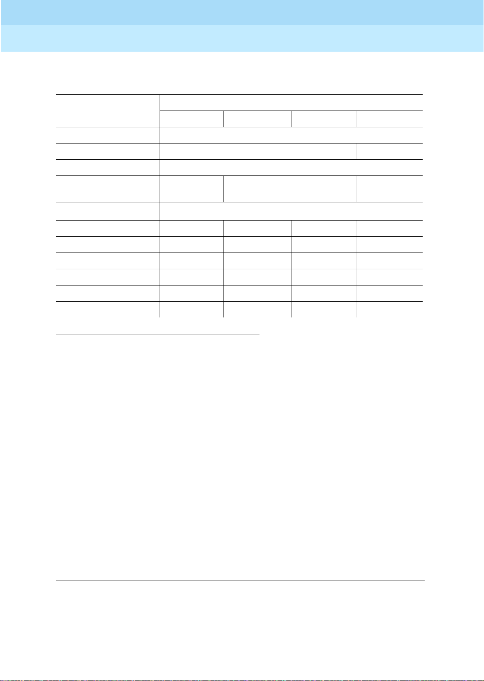
DEFINITYEnterpriseCommunicationsServerandSystem75andSystem85
Terminals and Adjuncts Reference
Administration
5
555-015-201
Table 5-1. DEFINITY G1 and G3, DEFINITY ECS, and System 75
Voice Terminal Administration — Continued
System
Voice Terminal S75 R1V1 S75 R1V2 S75 R1V3 G1 and G3
7410 7403D
7410 Plus 7403D 7410D
7434 7405D
7444 7405D
DD
8403
8405B/8405B Plus 7403 7410
8405D/8405D Plus 7403 7410
8410B 7403 7410
8410D 7403 7410
8411B 7403 7410
8411D 7403 7410
7405D
or 7407D
7405
‡
‡
§
§
¶
¶
*
†
Issue 11
December 1999
5-4Aliasing
7434D
or 7407D
*
* CAVEATS for administration of the 7444 voice terminal:
If the 7444 voice terminal is administered as a 7405D or a 7407D, the following caveats apply:
■ Only 10 call appearance buttons can be administered with two lights, a red and a green light.
■ If the voice terminal is administered as a 7407D, the S1 switch on the back of the 7444 voice terminal must
be in the OFF position.
When the 7444 voice terminal is administered as a 7405D or a 7434 voice terminal, the following caveats apply:
■ The S1 switch on the back of the 7444 voice terminal must be in the ON position.
■ Only one line of the display will show switch-related information.
When a 7444 is administered as a 7434, DEFINITY G1 allows a maximum of 10 appearances of the primary line
while DEFINITY G2 allows a maximum of 12 appearances. Each switch handles appearances of other lines (that
is, lines used in Bridging, Call Pickup, etc.) in a different manner. Information about administering these
appearances can be found in switch documentation and help screens.
† If the 8403 is connected to a DEFINITY G3V3 (and later), the 8403 can be administered as itself.
‡ Ifthe 8405B or 8405B Plus is connected to a DEFINITY G3i or G3r, it can be administered as a 7410 Plus. If the
8405B or 8405B Plus is connected to a DEFINITY G3V3 (or later), the set can be administered as an 8410B. If
the 8405D or 8405D Plus is connected to a DEFINITY G3V3 (or later), the set can be administered as an 8410D.
§ Ifthe 8410B is connected to aDEFINITY G3i or G3r, it can beadministered as a 7410 Plus. If the 8410B or 8410D
is connected to a DEFINITY G3V3 (or later), the set can be administered as itself.
¶ If the 8411B is connected to a DEFINITY G3i or G3r, it can be administered as a 7410 Plus. If the 8411B is
connected to a DEFINITY G3V3 (or later), the set can be administered as an 8410B. If the 8411D is connected
to a DEFINITY G3V3 (or later), the set can be administered as an 8410D.
DD = Digital Display Module
Continued on Next Page
Page 79

DEFINITYEnterpriseCommunicationsServerandSystem75andSystem85
Terminals and Adjuncts Reference
Administration
5
555-015-201
December 1999
Issue 11
Table 5-1. DEFINITY G1 and G3, DEFINITY ECS, and System 75
Voice Terminal Administration — Continued
System
Voice Terminal S75 R1V1 S75 R1V2 S75 R1V3 G1 and G3
8434/8434DX (for extra features)
8434/8434DX (for additional coverage)
602 CALLMASTER X X S
CALLMASTER II and III X X 602 CALLMASTER
7505 ISDN X S
7506 ISDN X S
7507 ISDN X S
8503T X S
8510T X S
8520T X S
MDC 9000 7303S Hybrid
MDW 9000 7303S Hybrid
MDW 9031DCP 8410D
*
*
7405+D+F
X 7434+D
‡
‡
5-5Aliasing
†
* CAVEATS for administration of the 8434 voice terminal:
The 8434 and 8434DX may be aliased as a 7405+D+F to support all system features. However, in this case, while all the call
appearance/feature buttons AND the softkey features will be functional, there can be a maximum of only 10 call appearances.
On the 7405, the Display Module is a 1-line display, and thus the 1-line display option should be selected. On some systems,
the 8434 and 8434DX can be aliased as a 7434+D or a 7444 to support coverage. In this case, there can be up to 34 call
appearances (including bridged call appearances), but the 15 softkey features will NOT be functional because the Feature Key
Module is not allowed with the 7434 or 7444. On the 7434, the Display Module is a 1-line display, and thus the 1-line display
option should be selected. If the set is administered as a 7444, it can be optioned for a 2-line display.
An 8434 or 8434DX connected to a DEFINITY G3V2 can be administered as a 7444; an 8434 or 8434DX connected to a
DEFINITY G3V3 (or later) can be administered as itself.
† An 8510T voice terminal connected to a DEFINITY G1 or G3 can be administered as itself, but an 8510 data terminal must be
administered as a 7507.
‡ A MDC 9000 Cordless Telephone or a MDW 9000 Wireless Telephone connected to a DEFINITY G3V3 (or later) can be
administered as itself.
S = Administered as Self
X = Not Allowed
+D = with Display Module
+F = with Feature Key Module
Page 80

DEFINITYEnterpriseCommunicationsServerandSystem75andSystem85
Terminals and Adjuncts Reference
Administration
5
555-015-201
December 1999
Table 5-2. DEFINITY G1 and G3, DEFINITY ECS, and System 75 Terminal
and Module Administration
System
PCs and
Digital Modules S75 R1V1 S75 R1V2 S75 R1V3 G1 and G3
PC/PBX Platform 7405D
DD and DM
MPDM S
MTDM S
7400A DM PDM or TDM (modem pool only) S
7400Band 7400B Plus DM PDM (data only) or DM (voice and data) S
High Speed Link PDM
3270A DCP PDM
3270C DCP PDM
3270T DCP PDM
PC/ISDN Platform X X X X
PC
Issue 11
5-6Aliasing
S = Administered as Self
X = Not Allowed
PC = Personal Computer
DD = Digital Display Module
DM = Data Module
TDM=TrunkDataModule
PDM = Processor Data Module
Page 81

DEFINITYEnterpriseCommunicationsServerandSystem75andSystem85
Terminals and Adjuncts Reference
Administration
5
555-015-201
December 1999
Table 5-3. DEFINITY G2 and System 85 Voice Terminal Administration
System
Voice Terminal S85 R2V1 S85 R2V2 S85 R2V3 S85 R2V4 G2
500 A
2500 A
2500 YMGK A
8101/8102/8110 A
6201/6210/6220/6230
7101A A
7102A A
7102 Plus A
7103A A
7104A A
10 MET 7203H
20 MET 7205H
30 MET 7205H
“MERLIN” SMALL X
“MERLIN” MEDIUM 7303S
“MERLIN” LARGE 7305S
7401D 7403D S
7401 Plus 7403D 7401D
7402 Plus 7403D 7410D
7404 7403D DM S
7406D 7405D DD S
7406BIS 7405D DD S
7406 Plus 7405D DD 7406D or 7406BIS
7407D 7405
DD
Enhanced 7407D 7405D
DD
7407 Plus 7405D
DD
S
7407D
7407D
Issue 11
5-7Aliasing
X = Not Allowed
A = Administered as Analog On-premises or Off-premises
S = Administered as Self
DD = Digital Display Module
DM = Data Module (DTDM or ADS)
Continued on Next Page
Page 82

DEFINITYEnterpriseCommunicationsServerandSystem75andSystem85
Terminals and Adjuncts Reference
Administration
5
555-015-201
December 1999
Issue 11
Table 5-3. DEFINITY G2 and System 85 Voice Terminal Administration — Continued
System
Voice Terminal S85 R2V1 S85 R2V2 S85 R2V3 S85 R2V4 G2
7410D 7403D S
7410 Plus 7403D 7410D
7434D 7405D S
7444 7405DDD 7405D DD
or 7407D
*
8403 7405
8405B/8405B Plus 7403 7410D
8405D/8405D Plus 7405+D
8410B 7403 7410D
8410D 7405+D
8411B 7403 7410D
8411D 7405+D
7434D
or 7407D
5-8Aliasing
*
* CAVEATS for administration of the 7444 voice terminal:
If the 7444 voice terminal is administered as a 7405D or a 7407D, the following caveats apply:
■ Only 10 call appearance buttons can be administered with two lights, a red and a green light.
■ If the voice terminal is administered as a 7407D, the S1 switch on the back of the 7444 voice terminal must be in the OFF
position.
When the 7444 voice terminal is administered as a 7405D or a 7434 voice terminal, the following caveats apply:
■ The S1 switch on the back of the 7444 voice terminal must be in the ON position.
■ Only one line of the display will show switch-related information.
When a7444 isadministered as a 7434, DEFINITY G1 allows a maximum of 10 appearances of the primary line while DEFINITY
G2 allows a maximum of 12 appearances. Each switch handles appearances of other lines (that is, lines used in Bridging, Call
Pickup, etc.) in a different manner. Information about administering these appearances can be found in switch documentation
and help screens.
S = Administered as Self
DD = Digital Display Module
Continued on Next Page
Page 83

DEFINITYEnterpriseCommunicationsServerandSystem75andSystem85
Terminals and Adjuncts Reference
Administration
5
555-015-201
December 1999
Issue 11
Table 5-3. DEFINITY G2 and System 85 Voice Terminal Administration — Continued
System
Voice Terminal S85 R2V1 S85 R2V2 S85 R2V3 S85 R2V4 G2
8434/8434DX
(for extrafeatures)
8434/8434DX (for
additional coverage)
602 CALLMASTER X S
CALLMASTER II and III X 602 CALLMASTER
7505 ISDN X S
7506 ISDN X S
7507 ISDN X S
8503T X 7505
8510T X 7507
8520T X 7507
MDC 9000 7303SHybrid
MDW 9000 7303S Hybrid
MDW 9031 8410D
*
*
7405+D+F
X 7434+D
5-9Aliasing
* CAVEATS for administration of the 8434 voice terminal:
The 8434 may be aliased as a 7405+D+F to support all system features. However, in this case, while all the call
appearance/feature buttons AND the softkey features will be functional, there can be a maximum of only 10 call appearances.
On the 7405, the Display Module is a 1-line display, and thus the 1-line display option should be selected.
On some systems, the 8434 can be aliased as a 7434+D or a 7444 to support coverage. In this case, there can be up to 34 call
appearances (including bridged call appearances), but the 15 softkey features will NOT be functional because the Feature Key
Module is not allowed with the 7434 or 7444. On the 7434, the Display Module is a 1-line display, and thus the 1-line display
option should be selected. If the set is administered as a 7444, it can be optioned for a 2-line display.
X = Not Allowed
A = Administered as Analog On-premises or Off-premises
S = Administered as Self
Page 84

DEFINITYEnterpriseCommunicationsServerandSystem75andSystem85
Terminals and Adjuncts Reference
Administration
5
555-015-201
December 1999
Table 5-4. DEFINITY G2 and System 85 Terminal and Module Administration
System
Display Terminals
and Digital Modules S85 R2V1 S85 R2V2
PC/PBX Platform 7405D
DD and DM
BCT 513 X EIA PORT
MPDM PDM
MTDM TDM
7400A DM PDM or TDM (modem pool only) S
7400B and 7400B Plus DM PDM (data only) or DM (voice and data) S
7500B DM X S
High Speed Link PDM
3270A DCP PDM
3270C DCP PDM
3270T DCP PDM
PC/ISDN Platform X GTA
S85
R2V3
PT 510D PC
S85
R2V4 G2
Issue 11
5-10Aliasing
S = Administered as Self
X = Not Allowed
PC = Personal Computer
DD = Digital Data Module
DM = Data Module
PDM = Processor Data Module
TDM=TrunkDataModule
GTA = Generalized Terminal Administration (see System 85 and DEFINITY G2
Button and FeatureCaveats section)
Page 85

DEFINITYEnterpriseCommunicationsServerandSystem75andSystem85
Terminals and Adjuncts Reference
Administration
5
555-015-201
December 1999
Button and Feature Caveats
System 75, DEFINITY G1 and G3, and DEFINITY ECS
Table 5-5. Button and Feature Caveats for DEFINITY G1 and G3 and System 75
Issue 11
5-11Button and Feature Caveats
Buttons
that Do
NOT
Terminal Aliased As Switch Release
7401D 7403D R1V1—R1V3 10 —
7406D01A—
7406D04A
7406D05A,
7406D06A
8405
(callappearance/
feature buttons)
CALLMASTER II and III 602 CALLMASTER R1V3 (See Note 3) 7—10 22 and 28
* Do not assign features to these buttons.
Note 1:
7406D02A, 7406D04A, and 7406D06A aliased as 7405D;
7406D02A, 7406D04A, and 7406D06A with 7400B Plus aliased as 7405D with DM;
7406D01A, 7406D03A, and 7406D05A aliased as 7405D with DD;
7406D01A, 7406D03A, and 7406D05A with 7400B Plus aliased as 7405D with DM and DD;
7406D01A and 7406D02A with Z703A DSU aliased as 7405D with DM and DD.
Note 2:
Reserved for Speaker and Mute.
Note 3:
Not supported in earlier releases.
Note 4:
These buttons are used for the Log in and Release features.
7405D
(SeeNote1)
7405D
(SeeNote1)
Self R1V2—R1V3,
8410 DEFINITY
G3V3 or later
R1V1 6—10,
R1V1 6—10,
G1
*
Exist
19—24
19—24
—2,3
6—10 —
Do NOT
Assign
Features to
Button(s)
—
2, 3
(See Note 2)
(See Note 2)
Page 86

DEFINITYEnterpriseCommunicationsServerandSystem75andSystem85
Terminals and Adjuncts Reference
Administration
5
555-015-201
December 1999
System 85 and DEFINITY G2
Table 5-6. Button and Feature Caveats for DEFINITY G2 and System 85
Buttons
that Do
NOT
Terminal Aliased As Switch Release
7401D 7403D R2V1—R2V3 12 —
7406D01A—
7406D04A
7406D05A,
7406D06A
CALLMASTER II and
III
7405D
(See Note 1)
7405D
(See Note 1)
Self R2V4—G2 — 14, 15
602 CALLMASTER R2V2—R2V4
R2V1—R2V3 8—12,
R2V1—R2V3 8—12,
(SeeNote3)
*
Exist
31—36
31—36
9—12 24 and 30
Do NOT
Assign Features
to Button(s)
(See Note 2)
(See Note 2)
(See Note 4)
Issue 11
5-12Button and Feature Caveats
—
14, 15
* Do not assign features to these buttons.
Note 1:
7406D02A, 7406D04A, and 7406D06A aliased as 7405D;
7406D02A, 7406D04A, and 7406D06A with 7400B Plus aliased as 7405D with DM;
7406D01A, 7406D03A, and 7406D05A aliased as 7405D with DD;
7406D01A, 7406D03A, and 7406D05A with 7400B Plus aliased as 7405D with DM and DD;
7406D01A and 7406D02A with Z703A DSU aliased as 7405D with DM and DD.
Note 2:
Reserved for Speaker and Mute.
Note 3:
Not supported in R2V1.
Note 4:
These buttons are used for the Log In and Release features.
PC/ISDN Platform (DEFINITY G2). To administer the PC/ISDN Platform, the
Generalized T erminal Administration (GTA) capability of DEFINITY G2 must be
used. Below is an overview of how to administer it. See the
and Reference Manual
for detailed instructions.
PC/ISDN Administration on DEFINITY G2. Ordinary BRI terminals usedwith
DEFINITY G2 require initialization. They also support Maintenance Information
Messages (MIMs). Because PC/ISDN supports neither MIMs nor terminal
initialization, the system administrator must have created a
type of terminal being used with PC/ISDN. If the terminal is to have an associated
display, the display type must be changed to
6
for
personal computer
terminal thus created is simply a copy of the ter minal type f or the terminal at hand
with the ISDN-MIM feature set to
None
and the display type s et to6. For example,
if the terminal to be administered is an AT&T model 7507, the system
PC/ISDN Installation
terminal type
for each
.Each
Page 87

DEFINITYEnterpriseCommunicationsServerandSystem75andSystem85
Terminals and Adjuncts Reference
Administration
5
555-015-201
administrator mi ght copy the 7507 termi nal (type 57) to a new ter minal type (that
is, type 157) and modify it to exclude sup port of the ISDN-MIM f eat ure.
Issue 11
December 1999
5-13Button and Feature Caveats
Page 88

DEFINITYEnterpriseCommunicationsServerandSystem75andSystem85
Terminals and Adjuncts Reference
Administration
5
555-015-201
Issue 11
December 1999
5-14Button and Feature Caveats
Page 89

DEFINITYEnterpriseCommunicationsServerandSystem75andSystem85
Terminals and Adjuncts Reference
Voice Terminal Features
6
555-015-201
Voice Terminal Features
The voice terminals connected to the DEFINITY Communications System
Generic 1, Generic 2, and Generic 3, the DEFINITY Enterprise Communications
Server (ECS), System 75, and System 85 provide a wide range of features. The
following tables provide information on the major features of a particular type of
telephone or voice terminal.
Issue 11
December 1999
6-1
6
■ Tables 6-1, 6-2, 6-3, 6-4, and 6-5 show the features that are available with
single-line telephones and voice te rminals, and the 6402 and 640 2D
telephones, and the 7401D and 7401 Plus Voice Terminals.
■ Tables 6-6 shows the feat ures that are available with
multiple-appearance hybrid voice terminals.
■ Tables 6-7, 6-8, 6-9, 6-1, and 6-11 shows the features that are available
with multiple-appearance digital voice termin als.
■ Table 6-12 shows the feat ures available with the ISDN voice terminals.
Page 90

DEFINITYEnterpriseCommunicationsServerandSystem75andSystem85
Terminals and Adjuncts Reference
Voice Terminal Features
6
555-015-201
December 1999
Issue 11
6-2
Table 6-1. Single-Line and 7401 Voice Terminal Features
(500 Telephone and 2500 Series Telephones)
Te le ph o ne s
Physical Features
500
2500/
2554
2500
DMGC
2500
YMGK
2500 MMGL
and 2500/2554
MMGM and
MMGN
2500 YMGL
and 2500/2554
YMGM and
YMGP
Analog XX X X X X
Digital
Touch-Tone Dial XX X X X
Rotary Dial X
Message Li ght XX X
Dial Access to
XX X X X X
Features
Built-in Digital
Display
Recall Button XX
Mute Button X
Flash Button X
Redial Button X
Hold Button X
Personalized
Ringing
Tone Ringing XX X X
Optional
Enhancements:
Message Waiting
Adjunct
Headset Adapter
External
Speakerphone
X
Page 91

DEFINITYEnterpriseCommunicationsServerandSystem75andSystem85
Terminals and Adjuncts Reference
Voice Terminal Features
6
555-015-201
December 1999
Table 6-2. Single-Line Telephones and 7401 Voice Terminal Features
(6200 Series Telephones)
Te le ph o ne s
Physical Features 6210 6218 6220
Analog XXX
Digital
Touch-Tone Dial XXX
Message Li ght XXX
Dial Access to F eatu res XXX
Built-in Digital Display X
Hold Button XXX
Flash Button XXX
Redial Button XXX
Issue 11
6-3
Personalized Ringing XX
User Programming Button XX
Programmable D ialing Buttons 10 10
Lower Button
Pause Button X
(Set) Clock Button
Timer Button
Built-in Speakerphone X
Mute Button X
Tone Ringing XXX
Ringer Volume Control XXX
Data Jack XXX
Power Jack
Adjunct Equipment Jack
Page 92

DEFINITYEnterpriseCommunicationsServerandSystem75andSystem85
Terminals and Adjuncts Reference
Voice Terminal Features
6
555-015-201
December 1999
Table 6-3. Single-Line Telephones and 7401 Voice Terminal Features
(8100 Series Telephones)
Te l e p h on e s
Physical Features 8101/8101M 8102/8102M 8110/8110M
Analog XXX
Digital
Touch-Tone Dial XXX
Message Li ght XXX
Dial Access to F eatu res XXX
Built-in Digital Display
Hold Button XXX
Flash Button XXX
Issue 11
6-4
Redial Button XXX
One-Way Li sten-Only
Speaker
Persona lized Ringing XXX
User Programm ing Button XX
Pause Butto n XX
Auto Answer Button X
Built-in Speakerphone X
Tone Ringing XXX
Adjunct Equipment Jack X
Optional Equipment
Headset Adapter
X
Page 93

DEFINITYEnterpriseCommunicationsServerandSystem75andSystem85
Terminals and Adjuncts Reference
Voice Terminal Features
6
555-015-201
December 1999
Issue 11
6-5
Table 6-4. Single-Line and 7401 Voice Terminal Features
(7101A through the 7104A Voice Terminals)
Voice Terminals
Physical Features
7101A 7102A
7102
Plus
7103A
Fixed
7103A
Prog. 7104A
Analog XXXX X X
Digital
Touch-Tone Dial XXX X X X
Message Li ght XXX X X
Dial Access to F eatu res XXX X X X
Built-in Digital D isplay X
Feature-only Buttons 8 10 16
Recall Button XXX X X X
One-Way Listen-Only Speaker X
Disconnect Butto n XXX
Personalized Ringing XXX
Last Number Dialed
X
(or Redial) Button
User Programming Button XX
Built-in Speakerphone
Tone Ringing XXXX X X
Optional Enhancements:
XX X
Headset Adapter
External Speakerphone XX X
Page 94

DEFINITYEnterpriseCommunicationsServerandSystem75andSystem85
Terminals and Adjuncts Reference
Voice Terminal Features
6
555-015-201
December 1999
Issue 11
Table 6-5. Single-Line Telephone and 7401 Voice Terminal Features
(6402 Telephones and the 7401 Voice Terminals)
Telephones/Voice Terminals
7401 Plus
(See Note 1)
Physical Features
6402 6402D
7401D
(See Note 1)
Analog
Digital XX X X
Touch-Tone Dial XX X X
Message Light XX X X
Dial Access to Features XX X X
Built-in Digital Display X
6-6
Hold, Conferenc e, Transfer,
XX
and Redial Button
Feature (Directory) Button XX X X
Shiftable Dial Pad Features 12 12 12 12
One-Way Listen-Only Speaker XX
Message Li ght XX X X
Volume Control Button XX
Personalized Ringing XX X X
Adjunct Equipment Jack X
Optional Equipment
Headset Adapter
XX
X
External Speakerphone X
Note 1:
This model has two “virtual” appearances, but no call appearance buttons.
Page 95

DEFINITYEnterpriseCommunicationsServerandSystem75andSystem85
Terminals and Adjuncts Reference
Voice Terminal Features
6
555-015-201
December 1999
Table 6-6. Multi-Appearance Hybrid Voice Terminal Features
(The 7200 Series and the 7300 Series Voice Terminals)
Voice Terminals
Physical Features 7203H 7205H 7303S 7305S
Issue 11
6-7
Call Appearance Feature Buttons
10 10 10 10
with In-Use and Status Lights
Feature-only But tons 24 24
Dial and Buttons Access to Features XXXX
Conference, Tra nsfer, Hold, and
XXXX
Drop Buttons
Disconnect Butto n XX
Recall Button XXXX
Self-Test Switch XX
Message Li ght XXXX
One-Way Li sten Only Speaker XX
Built-in Digital Display
Built-in Speakerphone
Persona lized Ringing
AC Powered
DC Powered XXXX
Optional Enhancements:
XXXX
Headset Ad apte r
External Speakerphone XXXX
Call Coverage Module X
Function Key M odule X
Page 96
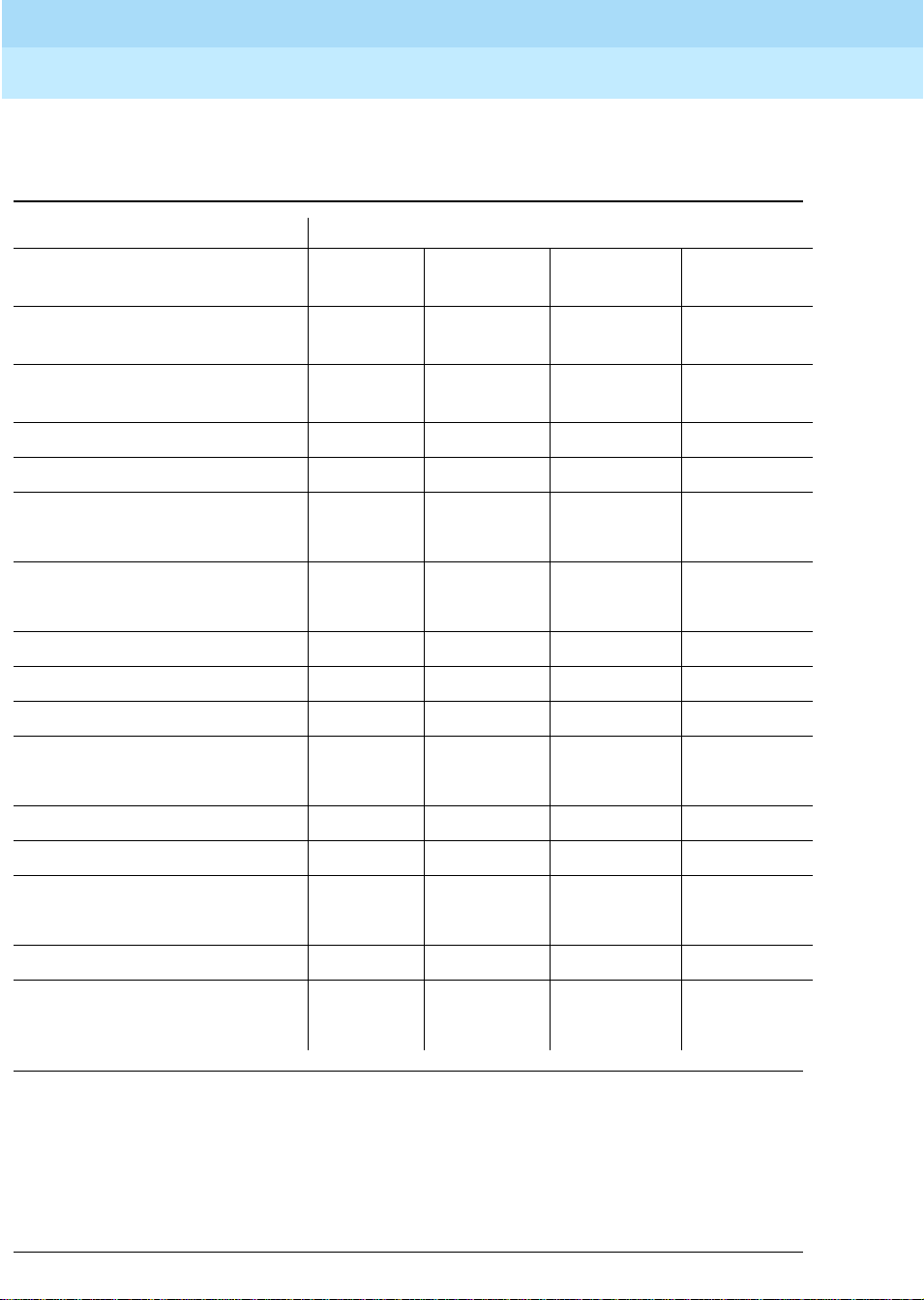
DEFINITYEnterpriseCommunicationsServerandSystem75andSystem85
Terminals and Adjuncts Reference
Voice Terminal Features
6
555-015-201
Table 6-7. Multi-Appearance Digital Voice Terminal Features
(The 6400 Series Voice Terminals)
Physical Features Voice Terminals
Issue 11
December 1999
6-8
Call Appearance / Feature
Buttons
Dial and Button Access to
6408 and
6408+
6408D and
6408D+
6416D+ and
6416D+M
6424D+ and
6424D+M
XX X X
Features
Conference, Transfer, Hold,
XX X X
and Redial Buttons
Self-Test Capability XX X X
Message Light XX X X
Built-in Speakerphone XX X X
(See Note 2) (See Note 2)
One-Way Listen-Only Speaker XX
(See Note 2) (See Note 2)
Mute Button XX X X
Personalized Ringing XX X X
Built-In Digital Display XXX
Headset Jack XX
(See Note 3) (See Note 3)
AC Powered
DC Powered (supplied by PBX) XX X X
Optional Enhancements:
Headset Adapter XX X X
XM24 Expansion Module XX
100A Tip/Ring Interface Module XX
(See Note 3) (See Note 3)
Note 2:
The 6408+ and 6408D+ voice terminals have a two-way speakerphone. The 6408 and 6408D have a one-way
listen-only speaker.
Note 3:
Only the Modular 6416D+M and 6424D+M have a Headset jack and a Modular interface in the desktop stand which
willaccommodate the Tip/RingModule.
Page 97

DEFINITYEnterpriseCommunicationsServerandSystem75andSystem85
Terminals and Adjuncts Reference
Voice Terminal Features
6
555-015-201
Table 6-8. Multi-Appearance Digital Voice Terminal Features
(The 7402 Plus through the 7406 Plus Voice Terminals)
Issue 11
December 1999
6-9
Physical
Features
Call
Appearance/
Feature
Buttons
Feature-Only
Buttons
Shiftable
Feature Buttons
DialandButtons
Access to
Features
Conference,
Transfer, Hold,
and Drop
Buttons
Disconnect
Button
Self-Test
Capability
Voice Terminals
7402 Plus 7403D 7404D 7405D 7406D 7406BIS 7406 Plus
6 10610 5 5 5
24 X 1
889
X XXX X X X
X XXX X X X
XX
X XXX X X
Message Li ght X XXX X X X
Built-in
Speakerphone
Reset
X
(SeeNote4)
X
(SeeNote4)
XX
X
Speakerphone
Capability
Mute Button XX
Built-in Digital
Display
Personalized
XXXX
X
(SeeNote5)X(SeeNote5)X(SeeNote5)
Ringing
Built-in Data
X
Module and
Data Call in
Progress Light
Continued on Next Page
Page 98

DEFINITYEnterpriseCommunicationsServerandSystem75andSystem85
Terminals and Adjuncts Reference
Voice Terminal Features
6
555-015-201
Table 6-8. Multi-Appearance Digital Voice Terminal Features
(The 7402 Plus through the 7406 Plus Voice Terminals) — Continued
Issue 11
December 1999
6-10
Physical
Features
7402 Plus 7403D 7404D 7405D 7406D 7406BIS 7406 Plus
AC Powered X
DC Powered
XX XX X X
(supplied by
PBX)
Optional
XX XX X X
Enhancements:
Headset
Adapter
External
XX XX X X
Speakerphone
Digital
XX
Terminal
Data Modu le
Data Modu le
Base
Call Coverage
Module
Function Key
Module
Voice Terminals
X
X
X
Digital Display
X
Module
Messaging
X
Cartridge
7400B+ Data
X XXX X X X
Module
Note 4:
The 7402 Plus and 7406D01A — 7406D04A voice terminals have a one-way listen-only speaker.
Note 5:
The following 7406 sets have built-in displays: 7406D01A, 7406D03A, 7406D05A, and 7406D07A.
Page 99

DEFINITYEnterpriseCommunicationsServerandSystem75andSystem85
Terminals and Adjuncts Reference
Voice Terminal Features
6
555-015-201
Table 6-9. Multi-Appearance Digital Voice Terminal Features
(The 7407 through the 7444 Voice Terminals)
Voice Terminals
Physical Features
7407D
Enhanced
7407D
7407
Plus 7410 7410 Plus 7434 7444
Issue 11
December 1999
6-11
Call Appearance/
10 10 10 10 10 34 34
Feature Buttons
Feature-only Buttons 11 24 24
Dual-Function
11
Feature Buttons
Display Control Buttons 7 7 7
Dial and Button Access
XXXXXXX
to Features
Conference, Transfer,
XXXXXXX
Hold, and Drop Buttons
Self-Test Capability XXXXXXX
Message Light XXXXXXX
Built-in Speakerphone XXX X
(SeeNote6)
Reset Speakerphone
XX
X
Capability
Mute Button XX X
Built-in Digital Display XXX X
Personalized Ringing XXXXXXX
Continued on Next Page
Page 100

DEFINITYEnterpriseCommunicationsServerandSystem75andSystem85
Terminals and Adjuncts Reference
Voice Terminal Features
6
555-015-201
Table 6-9. Multi-Appearance Digital Voice Terminal Features
(The 7407 through the 7444 Voice Terminals) — Continued
Voice Terminals
Physical Features
7407D
Enhanced
7407D
7407
Plus 7410 7410 Plus 7434 7444
AC Powered X
Issue 11
December 1999
6-12
DC Powered
XXXX XX
(supplied by PBX)
Optional Enhancements:
X X X X XX
Headset Adapter
External Speakerphone XXXX X X
Data M odule Base X
Call Coverage Module X
Digital Display Module X
7400B+ Data M odule XXXXXXX
Note 6:
The 7410D02A voice terminal has a one-way listen-only speaker.
 Loading...