

Page 1
SUPERPIPE 95/155
HARDWARE INSTALL GUIDE
Lucent Technologies
Part Number: 7820-0257-002
For software version 7.4.10
March 2000
1
Page 2
Before You Begin
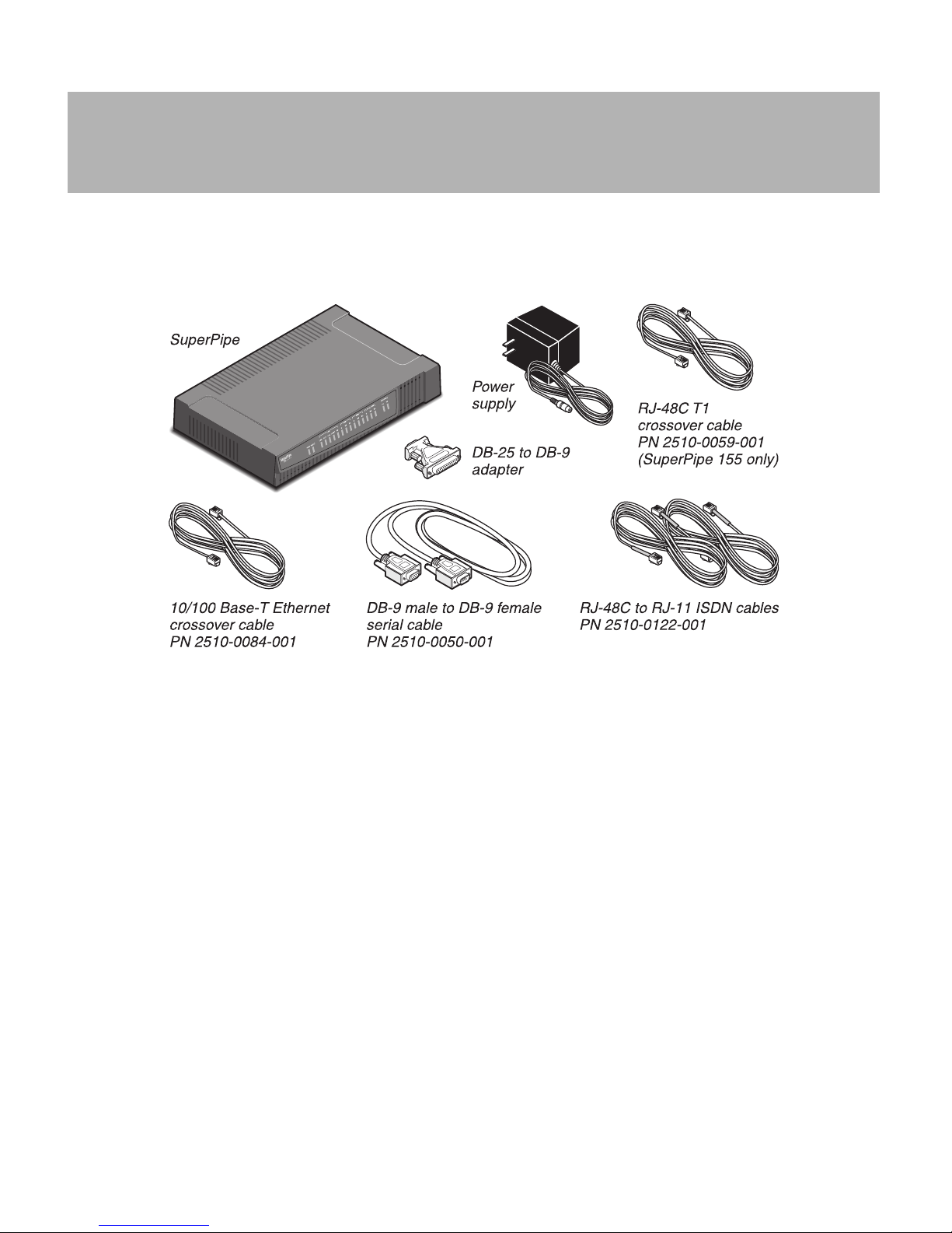
Review Package Contents
The SuperPipe package also contains:
• Hardw are Install Gu ide and Quick
Configuration Guide.
• Pipeline Companion CD-ROM.
• Warranty card.
• For SuperPipe155 only, one RJ-48C T1
crossover cable (part num ber 2510 -00 59-001).
• Power plug adapters for international units.
Also, please ensure that you have the following.
• WAN interface(s)
–ISDN
– T1 or E1 service (SuperPipe 155 only)
• A computer with a serial port and a 10/100
Base-T Ethernet interface.
• If you have the V.35 version of the SuperPipe
155, you will need a V.35/X.21 cable.
2
Page 3
1
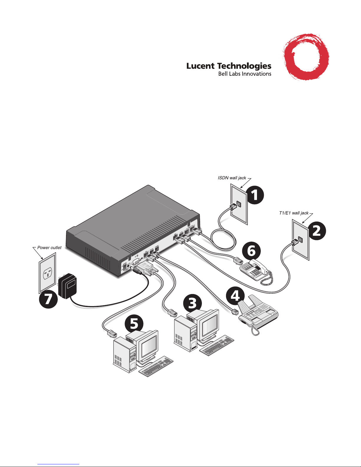
Connect ISDN BRI Line(s)
This section describe s how to connect an IS DN BRI
line to the SuperPipe. If you are not connecting an
ISDN line go on to step 2. Otherwise, refer to the
section that applies to you:
• Connect an ISDN BRI line with a U interface
• Connect an ISDN BRI line with an S interface
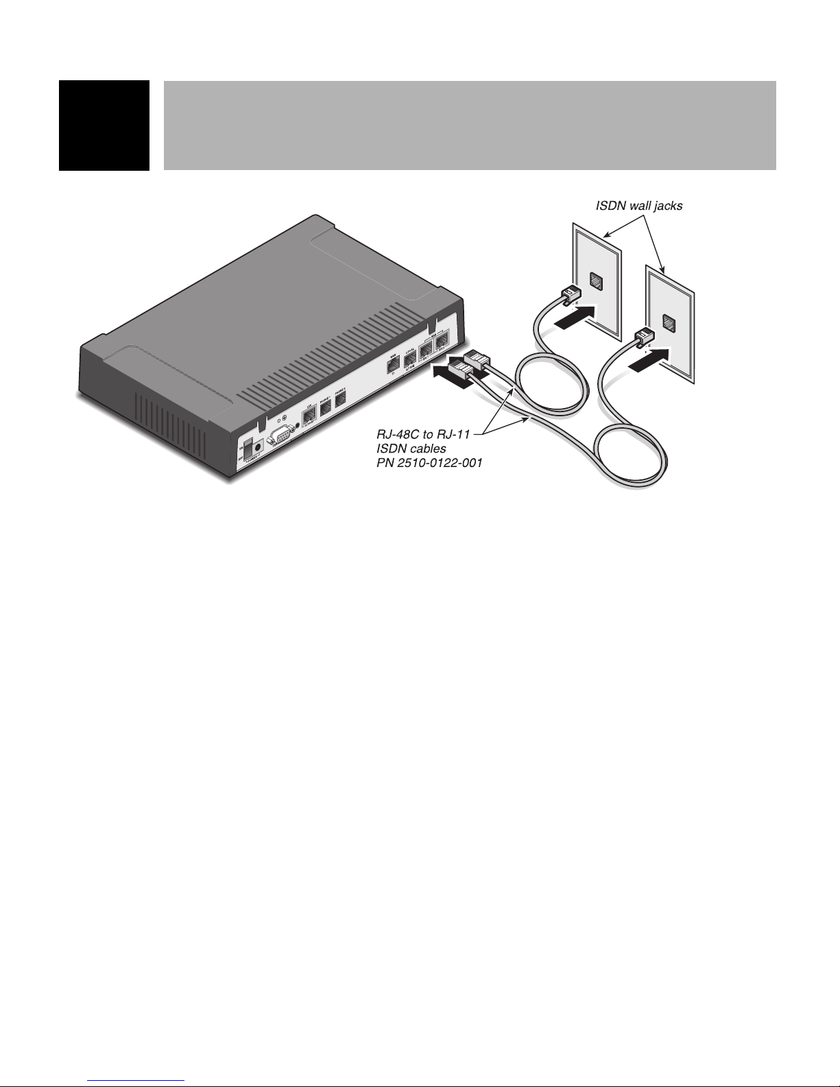
Connect an ISDN BRI line with
a U interface
Cable needed: RJ-48C to RJ-11 ISDN cable (provided, has blue ends).
T o connect an ISDN BRI line with a U interface, do
the following:
1 Insert the larger jack of the cable with the blue
ends (RJ-48C to RJ-11 ISDN) into one of the
WAN-BRI jacks on the back of the SuperPipe.
2 Insert the other end of the cable into the ISDN
wall jack.
Connect an ISDN BRI line with
an S interface
To connect an ISDN BRI line with an S interface,
do the followi ng:
Cable needed: RJ-48C to RJ-11 ISDN cable
(provided , has blue en ds).
1 Insert the larger jack of the cable with the blue
ends (RJ-48C to RJ-11 ISDN) into one of the
WAN-BRI jacks on the back of the SuperPipe.
2 Insert the other end of the cable into an NT-1 o r
an ISDN wall jack with an integrated NT-1.
3 T o connect an additional ISDN BRI line, r epeat
steps 1 and 2.
3 T o connect an additional ISDN BRI line, repeat
steps 1 and 2.
3
Page 4

2
Connect T1, E1 or V .35
(Model 155)
If you are not connectin g a T1 or E1 or s eri al WAN
line, go on to Step 3. Otherwise, refer to the appropriate section.
T1 or E1 Connection
Cable needed: RJ-48C T1/E1 crossover cabl e (provided with Su perPipe 155 only).
1 Connect your leased line to the port labeled
WAN T1 or E1 on the SuperPipe’s back panel.
2 Connect the other end either d irectly to the wall
jack or through other network interface equipment.
3 After you inform your service provider that
your equipment is connected and ready for service, you are ready to start up the unit.
CAUTION: The RJ-48C cable provided
!
with your SuperPipe is for devices that
transmit on pins 4 and 5 and receive on
pins 1 and 2. Ask yo ur carrier w hat type
of cable to use, a straight-through or
crossover.
V.35 Connection
Cable needed: DB44-to-DB25 cable (not provided).
1 Connect the DB-44 end into the S-WAN port
on the back of the SuperPipe unit.
2 Connect the DB25 end into the V.35 port of the
other device.
4
Page 5

33
Connect Superpipe to Computer(s)
Refer to the section that applies to your network:
• Connect a single computer to a SuperPipe
• Connect your Superpipe to an existing 10/100
Base-T Ethernet network using a hub
Connect to a single computer
Cable Needed: Yellow-ended 10/100 Base-T
Ethernet crossover cable (provided).
1 Insert one end of the 10/100 Base-T cable into
the 10/100 Base-T jack on the back of the
SuperPipe.
2 Insert the other end of the cable into the 10/100
Base-T Ethernet jack on the computer.
Connect to an Ethernet hub
Cable Needed: 10/100 Base-T Ethernet cable (you
provide).
CAUTION: Do not use the 10/100 Base-
!
T crossover cable included with the
SuperPipe (part number 2510-0084-001)
to connect the SuperPipe to a 10/100
Base-T hub.
Connect Analog Equipment
4
The SuperPipe has two analog ports providing you
with the option of using “regular” telephones or fax
machines over your SuperPipe.
To connect a telephone or other analog telephone
equipment:
1 Connect one end of a modular telephone
hookup cable to a conventional telephone or
other telephone device.
2 Connect the other end of the cable to the Phone
port 1 on the SuperPipe. International
customers may need to insert an analog port
adapter into the SuperPipe analog port.
Note: You cannot place or receive calls until you
connect the power cable to the SuperPipe, configure
the ISDN line and configure one or both of the
SuperPipe Phone ports to use the ISDN WAN
channels.
5
Page 6

5
Connect to the Terminal Port
Connecting to the terminal (serial) port is one of
two methods by which you can enter settings and
run diagnostics using the on-board software of the
SuperPipe. Using the Ethernet connection is the
other method.
For PC Users
Cable needed: Serial cable (provided) and, possibly, a DB-9-to-DB25 serial cable adapter (provided).
For Unix Users
Cable needed: Serial cable (provided).
1 Connect a modem cable for the computer to the
Terminal port on the back of the SuperPipe.
2 Connect the other end of the cable to the serial
port on the computer.
For Macintosh U sers
1 Connect a modem cable to a serial connector
on your computer and note the serial port number.
2 If the plug at the other end of the modem cable
has 25 pins, connect the 25-to-9 pin adapter
included with the SuperPipe to the plug.
3 Connect the cable to the Terminal port on the
back of the SuperPipe unit.
Cable needed: Serial cable (you provide) and a 25pin-to-9 pin adapter (provided).
1 Connect the 25-to-9 pin adapter to the DB-25
end of a Macintosh modem cable.
2 Connect the cable to the Terminal port on the
back of the SuperPipe.
3 Connect the other end of the cable to a serial
port (either the Modem or Printer port) on the
computer.
6
Page 7

6
Connect ISDN BRI Equipment
The local BRI port allows you to support an ISDN
telephone, desktop CODEC video conferencing, or
other ISDN desktop equipment.
Cable needed: RJ-48C to RJ-11 ISDN cable.
If the two ISDN cables provided are already in use,
you must provide this cable.
1 Connect one end of the ISDN cable into the
line jack on the ISDN telephone or other ISDN
device.
Connect the Power Cable
7
1 Plug the end of the cord on the power supply
to the power jack of the SuperPipe.
2 Connect the other end of the cable to the local
ISDN S/T BRI port on the SuperPipe.
WARNING: Models with AC power
inputs are intended for use with a threewire grounding type plug--that is, a plug
that has a grounding pin. This is a safety
feature. Eq uipment groun ding is vita l to
ensure safe operation. Do not defeat the
purpose of the grounding type plug by
modifying the plug or using an adapter.
2 Connect the opposite end of the power unit
into the appropriate power cord provided.
3 Insert the opposite end of the power plug into
an electrical outlet.
4 Turn the power switch on the back panel to
“ON.” The PWR status light on the front panels illuminates indicating that the power is on.
If the power supply is fed from a power source
with no ground path, connect the unit chassis stud
to the power supply chassis ground via a solid
copper 12 AWG wire. If the power supply is fed
from an isolated power source, the chassis ground
must be connected directly to earth v ia a solid copper 12 AWG wire.
7
Page 8

Understanding the SuperPipe LEDs
Refer to the following illustration to understand the func tionality of the SuperPipe 155 and SuperPipe 95
front panel LEDs.
Power
ON (green)=
Power is being
supplied to the
unit.
OFF
=Power is
not being
supplied to
the unit.
ISDN BRI LEDs
--------------------------------B1/B2 Channel Activity
GREEN = data call
in progress.
AMBER = voice call
in progress.
Flashes when call is
initiated.
D Channel Activity
ON (green) =active ISDN line.
OFF = ISDN line inactive.
Flashes when line activation
is in progress.
Fault
OFF=
Functioning
correctly.
ON (red)
Problem
detected.
=
LAN LEDs
----------------------------------------------------------------LNK
ON (green)=Link active.
OFF=
Link inactive.
ACT
Flashes (green)
are transmitted or received.
COL
Flashes (amber)
collisions are taking place
on the Ethernet LAN.
when packets
when
T1/E1/V.35 Status
(SuperPipe 155)
------------------------ACT
ON=
Active link.
FLASHING=
OFF= Port
disabled
.
10/100BT
ON (green)
at 100 Mbps.
OFF
=Link running at 10 Mbps.
FD
ON (green)
simultaneous communication (full
duplex link).
OFF
=Information is carried in one
direction at a time (half duplex link).
Phone Port Status
--------------------------
ON (amber)=
is in use.
OFF=
Error.
for use.
Flashing
telephone port is ringing.
= Link running
= Allows bidirectional,
Telephone port
Telephone port is available
=Device connected to
8
 Loading...