

Page 1

Lucent Technologies
Bell Labs Innovations
PARTNER® II
Communications System
Release 4.1
Installation
518-455-333
Comcode 107879223
Issue 2
August 1996
Page 2

Copyright © 1996 Lucent Technologies
All Rights Reserved
Printed in U.S.A.
Lucent Technologies 518-455-333
Issue 2
August 1996
Notice
Every effort was made to ensure that the information in this book was complete and accurate at the
time of printing. However, information is subject to change.
Federal Communications Commission (FCC) Interference Notice
This equipment has been tested and found to comply with the limits of a Class A digital device,
pursuant to Part 15 of FCC rules. For additional FCC information, see Appendix C of the PARTNER
Communications System Programming and Use guide.
II
Canadian Emmissions Requirements
This digital apparatus does not exceed the Class A limits for radio noise emissions from digital
apparatus set out in the Radio Interference Regulations of the Industry Canada (lC). For additional
IC information, see Appendix C of the PARTNER
guide.
Le present appareil numerique n’emet pas de bruits radioelectriques depassant Ies Iimites
applicables aux appareils numeriques de la classe A prescrites dans Ie Reglement sur Ie brouillage
radioelectrique edicte par Ie ministere des Industrie Canada. Vous trouverez des renseignements
complémitaires à la annexe C de PARTNER
manuel.
II
Communications System Programming and Use
II
Communications System Programming and Use
Security
Toll fraud, the unauthorized use of your telecommunications system by an unauthorized party (for
example, persons other than your company’s employees, agents, subcontractors, or persons
working on your company’s behalf) can result in substantial additional charges for your
telecommunications services. You are responsible for the security of your system. There may be a
risk of toll fraud associated with your telecommunications system. You are responsible for
programming and configuring your equipment to prevent unauthorized use. Your system manager
should read all documents provided with this product to fully understand the features that can
introduce the risk of toll fraud and the steps that can be taken to reduce that risk. Lucent
Technologies does not warrant that this product is immune from or will prevent unauthorized use of
common-carrier telecommunication services or facilities accessed through or connected to it.
Lucent Technologies will not be responsible for any charges that result from such unauthorized use.
Trademarks
PARTNER MAIL, PARTNER MAIL VS, Magic on Hold, MLS-34D, MLS-18D, MLS-12D, MLS-12,
MLS-6, PARTNER, and SYSTIMAX are registered trademarks of Lucent Technologies.
Warranty
Lucent Technologies provides a limited warranty to this product. See Appendix B of the PARTNER II
Communications System Programming and Use guide.
Ordering Information
The order number for this book is 518-455-333. To order additional books, call 1 800 457-1235 in
the continental U.S. or 1 317 361-5353 outside the continental U.S. For information about ordering
other system reference materials, replacement parts, accessories, and other compatible equipment,
see “Product Ordering Information” in Appendix B of the PARTNER
Programming and Use guide.
II
Communications System
Support Telephone Number
In the continental U.S., Lucent Technologies provides a toll-free hotline 24 hours a day.
Call the hotline at
Outside the continental U.S., contact your Lucent Technologies Representative or local
Authorized Dealer.
1 800 628-2888
if you need assistance when installing your system.
Page 3

Installing the Hardware
Contents
Important Safety Instructions
Overview
An Example System Setup
Required Parts
Installation Guidelines
■
Telephones and Devices
■
Combination Extensions
Using a Direct Connection
Using a Bridging Adapter
Installation Procedures
■
Installing the Control Unit and Modules
■
Connecting Lines and Extensions
■
Connecting Caller ID Display Devices
■
Assembling System Phones
Desk Mounting
Wall Mounting
■
Connecting and Testing Telephones
■
Connecting Paging, Call Reporting (SMDR), and
Music-On-Hold Devices
Paging System
Call Reporting (SMDR) Printer
Music-on-Hold Audio Source
■
Connecting a PARTNER-CA48 Intercom Autodialer
Equipment Upgrades
■
Adding New Modules
■
Replacing System Modules
Specifications
ii
1
2
4
5
5
6
7
7
8
8
10
12
13
13
14
15
16
16
16
17
18
19
19
20
22
i
Page 4

Important Safety Instructions
The following list provides basic safety precautions that should always be
followed when using your telephone equipment:
1.
Read and understand all instructions.
2.
Follow all warnings and instructions marked on the product.
3.
Unplug all telephone connections before cleaning. DO NOT use liquid
cleaners or aerosol cleaners. Use a damp cloth for cleaning.
4.
This product should be serviced by (or taken to) a qualified repair center
when service or repair work is required.
5.
DO NOT use this product near water, for example, in a wet basement location.
6.
DO NOT place this product on an unstable cart, stand, or table.
7.
Never push objects of any kind into slots or openings as they may touch
dangerous voltage points or short out parts that could result in a risk of fire
or electric shock. Never spill liquid of any kind on the product.
8.
Avoid using the telephone during an electrical storm. There may be a remote
risk of electric shock from lightning.
DO NOT use the telephone to report a gas leak in the vicinity of the leak.
9.
10.
The product is provided with a three-wire grounding type plug. This is a
safety feature. DO NOT defeat the safety purpose of the grounding type
plug. DO NOT staple or otherwise attach the power supply cord to building
surfaces.
CAUTION:
DO NOT block or cover the ventilation slots and openings. They prevent the
product from overheating. DO NOT place the product in a separate enclosure
unless proper ventilation is provided.
Additional Safety Instructions for
Installation Personnel
1.
DO NOT install telephone wiring during a lightning storm.
2.
DO NOT install telephone jacks in a wet location unless the jack is specifically
designed for wet locations.
Never touch uninsulated telephone wires or terminals, unless the telephone
3.
line has been disconnected at the network interface.
4.
Use caution when installing or modifying telephone lines.
5.
The control unit must be securely wall mounted.
CAUTION:
If any wiring from the extension jacks leaves the building premises, you must
install Lucent Technologies IROB protectors (see “Requirements for
Out-of-Building Extensions” on page 24).
CAUTION:
Use only Lucent Technologies-manufactured PARTNER modules in the
PARTNER II Communications System.
CAUTION:
Environmental and electrical conditions must meet the specifications as listed
on pages 23 and 24.
SAVE THESE INSTRUCTIONS
ii
Page 5

Installing the Hardware
Overview
This guide explains how to install the PARTNER®
It begins with an example system setup, then shows the components you need
to install the system and gives general guidelines to consider before installation.
Next, it provides step-by-step instructions for connecting and testing the
components for initial installation and upgrades. Finally, it lists important system
specifications. Make sure that your installation meets all electrical and
environmental requirements.
If your company already has modular jacks for all outside lines and extensions,
you may be able to use the existing wiring to install the system hardware and
connect telephones to the system yourself. To have a Lucent Technologies
service technician install and customize your system or change existing wiring,
call 1 800 247-7000 (in the continental U.S.) or call your Lucent Technologies
Representative or local Authorized Dealer.
After installation, refer to the PARTNER
Programming and Use guide for programming instructions.
II
Communications System
II
Communications System.
Overview
1
Page 6

An Example System Setup
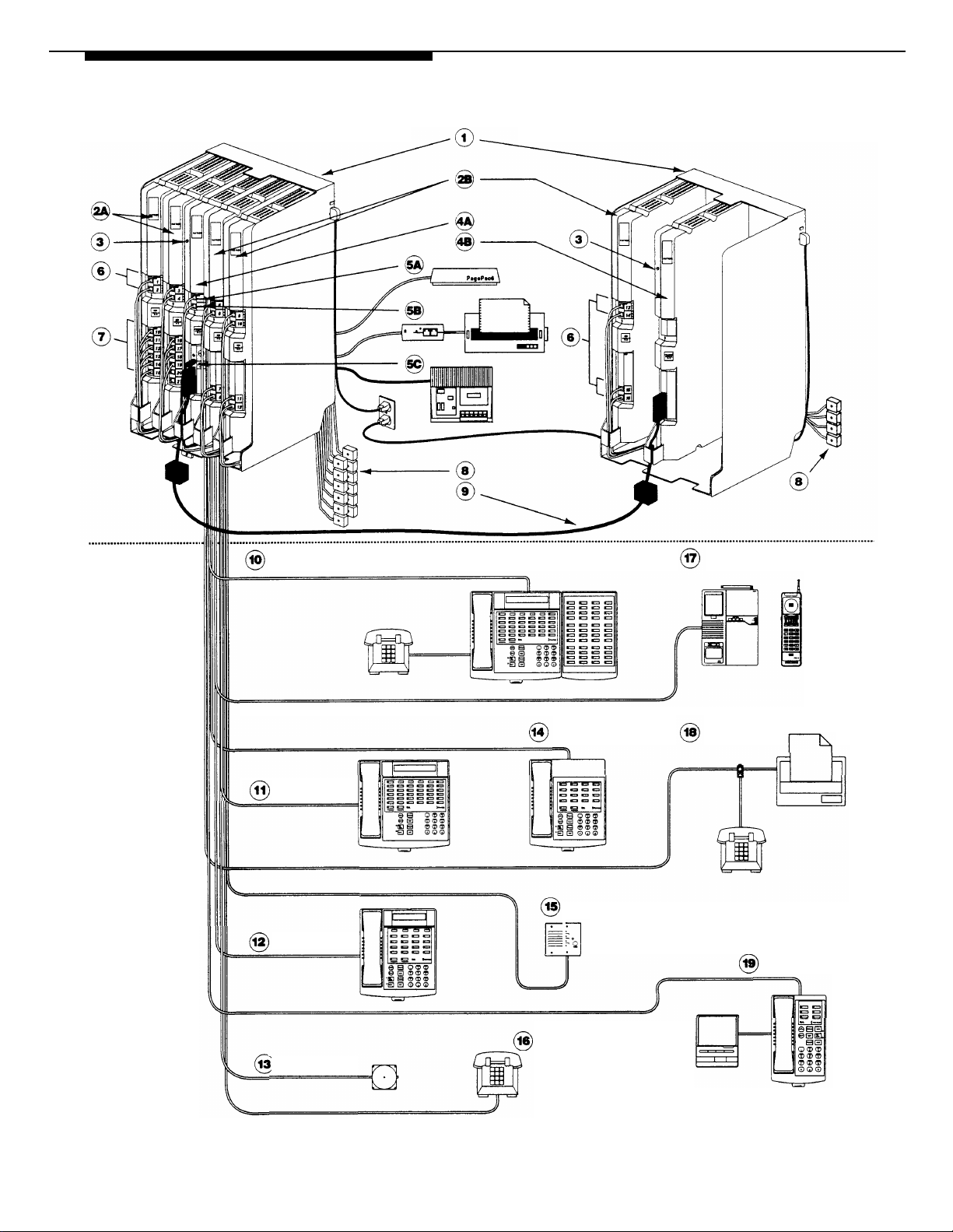
The next page shows a control unit with two 206 modules and
three 400 modules, giving the system a capacity of 16 outside lines and 12 extensions. Although your system may
differ, this example will give you an idea of the types of
equipment you can connect to it. System phones and
standard devices are connected to ten extensions. The
circled numbers in the figure refer to the following list, which
gives a brief description of the system’s components.
Control Unit
The control unit shows both the primary and the expansion
carriers, including these components:
Backplanes. The backplanes channel power to the
system and connect the system modules.
206 Modules. Each 206 module has jacks for two lines
and six extensions.
400 Modules. Each 400 module provides four line jacks
but no extensions. Notice that the 400 modules are
installed to the right of the 206 modules.
Grounding Screw.
solid copper wire to an approved earth ground.
Primary Processor Module. The primary processor
module contains the software that provides the system’s
features. It also has PAGE, SMDR, and MUSIC ON
HOLD jacks. (See 5 below.)
Expansion Processor Module.
processor module extends the primary processor
module’s software intelligence to the modules in the
expansion carrier.
PAGE Jack. A loudspeaker paging system plugs
directly into this modular jack. The system is compatible
with any Lucent Technologies paging system, including
the Lucent Technologies PagePac6® shown here.
SMDR Jack. A call reporting (or SMDR—Station
Message Detail Recording) device connects directly to
this jack. Lucent Technologies’ Call Accounting Terminal
is shown here.
MUSIC ON HOLD Jack. Lucent Technologies’ Magic on
Hold® is connected to this jack to provide customized
music and messages for callers on hold. Other types of
audio equipment* (including a CD player, cassette
player, or stereo receiver) can be connected using an
audio cord with an RCA phono plug (not supplied).
Line Jacks. The top two jacks on each 206 module, and
all four jacks on each 400 module, connect to outside
telephone lines.
Extension Jacks.
module connect inside wiring for telephones and other
telecommunications equipment.
Network Interface Jacks. These jacks provide access
to telephone lines from the local telephone company.
Each outside line is connected to the system by
plugging one end of the line cord into one of these jacks,
and the other end into a line jack on a 206 or 400 module.
Expansion Cable. The expansion cable connects the
primary processor module to the expansion processor
module.
* If you use equipment that rebroadcasts music or other copy-
righted materials, you may be required to obtain a license from
a third party such as ASCAP or BMI. The Magic on Hold system
does not require such a license. For more information, see
"Music-on-Hold Audio Source" later in this guide.
Attaches #12 AWG or #14 AWG
The expansion
The bottom six jacks on each 206
Extensions
Various devices—including system phones and industrystandard devices—can be connected to the modular wall
jacks. The modular wall jacks connect to the extension jacks
in the control unit by way of the building’s inside wiring.
Extension 10: These devices are connected:
■
PARTNER-34D Display Phone. Typically, the
receptionist at extension 10 has a PARTNER-34D
display phone like the one shown here. The display
shows the time, dialed numbers, the duration of calls,
and programming messages.
A display phone is required for system programming
at extension 10 or 11, or both. You can use an
18-button display phone only if there are no 34-button
display phones in the system.
■
PARTNER-CA48 Call Assistant™ Intercom
Autodialer. An Intercom Autodialer is connected to
the phone to dial extensions and transfer calls to them
with one touch and to see which extensions are busy.
■
Standard Touch-Tone Phone. During a power
failure, the PARTNER-34D phone on extension 10 will
not work, but the receptionist can use the standard
phone to place and receive calls on line 1.
Extension 11: PARTNER-34D Display Phone. Another
PARTNER-34D is connected to programming extension
11. You can program the system from this extension
while the receptionist at extension 10 is free to handle
calls.
Extension 12: PARTNER-18D Display Phone. This
display phone can handle 16 outside lines.
Extension 13: Bell. A loud bell is connected directly to
this extension jack. Any line programmed to ring on
extension 13 activates the loud bell—to alert users of an
incoming call in a large area, such as a warehouse.
Extension 14: PARTNER-18 Phone. This phone is
similar to the PARTNER-18D phone (see Extension 12),
but it has no display.
Extension 15: Doorphone. A doorphone is installed at
the building entrance. When someone at the entrance
presses the button on the doorphone, the designated
extensions in the office signal automatically. (Any
number of extensions can be designated as doorphone
alert extensions.)
Extension 16: Standard Phone. A standard touch-tone
phone (such as you might have in your home) is
connected directly to the extension jack.
Extension 17: MDC 9000 Cordless Phone. This
cordless phone works like the corded PARTNER-6 phone.
Extension 18: Fax Machine and Standard Phone. A
fax machine and standard phone share this extension.
This lets you have the use of another phone when the fax
machine is idle. (You can use a system phone at
another extension to monitor fax machine activity—see
“Fax Management Feature” under “Using Fax Machines”
in Chapter 4 of the PARTNER
Programming and Use guide.)
Extension 19: PARTNER-6 Phone and Answering
Machine.
A PARTNER-6 phone and an answering
machine are connected to this extension.
II
Communications System
2
An Example System Setup
Page 7
CONTROL
UNIT
Primary Carrier
Expansion Carrier
EXTENSIONS
Extension 10
Extension 11
Extension 12
Extension 14
Extension 15
Extension 17
Extension 18
Extension 19
Extension 13
Extension 16
An Example System Setup 3
Page 8
Required Parts
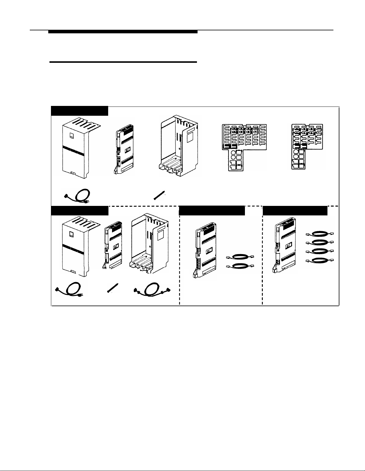
You will have up to four types of system component packages; Figure 1 shows
the contents of each package in the area marked by a dashed line. Check your
packages to be sure you have the parts shown here (if not, call for support as
instructed on the inside front cover of this guide).
Primary Carrier
Cover
AC Power Cord
Expansion Carrier
Cover
AC Power Cord
Figure 1. Required Parts
Processor Module
Long Screw
You will need to obtain four #12 screws of the appropriate type for the wall and
weight of each carrier (a carrier with four 206 modules and a processor module
weighs approximately 27.5 pounds or 12.3 kilograms.) You also need two
lengths of #12 AWG or #14 AWG solid copper wire (not to exceed 25 feet or 7.6
meters each) for grounding.
Primary
Processor
Module
Expansion
Backplane
Long Screw
Backplane
Expansion Cable
PARTNER-34D
Programming
Overlay
206E/206EC Module
7-foot
206E/206EC
Module
Telephone
Line Cords
PARTNER-18D
Programming
Overlay
400E/400EC Module
7-foot
400E/400EC
Module
Telephone
Line Cords
4
Required Parts
In addition, if you need modular telephone cords to connect the extension jacks
on the control unit to the modular connecting blocks for extensions in the
equipment room, short telephone cords or wall plates to wall mount
PARTNER-model phones, or a 355A/355AF adapter and D8W telephone cord to
connect a call reporting device, order them before installation. Refer to
“Product Ordering Information” in Appendix B of the PARTNER II
Communications System Programming and Use guide for ordering instructions.
Page 9

The 206EC and 400EC modules support the Caller ID feature. These modules
are required to provide Caller ID information on system display phones. You
must subscribe to Caller ID service from your local telephone company (if it is
available), and connect any lines associated with this service to the line jacks on
the 206EC and/or 400EC modules. Hereafter, references to 206 modules
include 206E, 206EC, and all 206 modules used with previous releases of the
product. Similarly, references to 400 modules include 400E, 400EC, and all 400
modules used with previous releases of the product.
NOTE:
A system display phone is required for programming at extension 10 and/or 11.
If you have any 34-button phones in the system, you must use a 34-button
display phone to program since an 18-button phone cannot be used to program
a 34-button phone. Also, if your system has both PARTNER-model and
MLS-model phones, it is recommended that you use a PARTNER-model display
phone at the programming extension.
Installation Guidelines
Telephones and Devices
You can connect the following telephones and devices to the system:
■
PARTNER-model, MLS-modeI, MDC 9000, and MDW 9000 System
Phones. System phones require at least two-pair wiring and are
compatible with Lucent Technologies 4-pair SYSTIMAX® wiring.
■
Call Assistant Intercom Autodialers with Busy Indication
(PARTNER-CA48 for PARTNER-model phones or MLS-CA24 for
MLS-model phones). You can connect an Intercom Autodialer to the
system phone at extension 10 and 11. The Intercom Autodialer connects
to the system phone using an adapter that is shipped with the autodialer.
■
Industry-Standard Devices. Industry-standard devices (including
standard phones) require one-pair mounting cords; Lucent Technologies
D2R mounting cords are recommended.
–
Standard Phones. Connect standard touch-tone or rotary dial
phones to the system for:
–
Power Failure Operation. During a power failure, system phones
will not work because they require power to operate. However, if
you connect standard phones to extensions 10, 16, 22, 28, 34,
40, 46, and 52, users can place and answer outside calls on lines
1, 3, 5, 7, 9, 11, 13, and 15, respectively. You can connect a
standard phone either alone or combined with a system phone.
For more information, see “Combination Extensions” on the next
page.
Installation Guidelines 5
Page 10

–
Hotlines. A hotline extension should have a standard phone,
rather than a system phone, but can ring any type of phone. An
internal hotline phone can also be set up to ring the paging
system, so announcements can be made over the loudspeaker.
Do not connect a hotline phone to extension 10, 16, 22, 28, 34, 40,
46, or 52, to keep them available for power failure use.
NOTE:
For message waiting capability, you must connect standard phones with
message waiting lights to Release 3.1 (R3.1) or later 206 modules, and
equip the system with an R3.1 or later processor module. This message
waiting capability does not apply to standard phones with neon-type
message waiting lights.
–
Auxiliary Equipment. There are a variety of ways to set up fax
machines, modems, and answering machines to work with the system.
To connect a telephone and a standard device on the same
extension, see “Combination Extensions” below.
■
Doorphones. You can connect up to two doorphones to the system. Do
not connect doorphones to extension 10, 11, 16, 17, 22, 23, 28, 29, 34,
35, 40, 41, 46, 47, 52, or 53.
■
Voice Messaging Systems. The system supports either of the following
voice messaging systems:
–
The PARTNER MAIL® System. This device connects to the system
through extension jacks. Do not connect PARTNER MAIL to extension
10, 16, 22, 28, 34, 40, 46, or 52, to keep them available for power
failure use.
–
The PARTNER MAIL VS® System. This device, which physically
resembles a 206 module, resides in the control unit.
■
Call Reporting Devices. You can connect either a serial printer or a call
accounting device, such as Lucent Technologies Call Accounting
Terminal, to the SMDR jack on the primary processor module to record
and/or analyze call activity.
■
In-Range Out-of-Building Protectors. Installing phones or other
standard devices (such as a doorphone) in a location other than the
building where the control unit is installed requires Lucent Technologies
In-Range Out-of-Building (IROB) protectors, to prevent damage due to
lightning. (IROBS must be installed by a qualified technician.)
Combination Extensions
You can connect a standard device (such as a standard phone or an answering
machine) on an extension by itself, or so that it shares an extension with another
piece of equipment (either another standard device or a system phone). An
extension with two devices connected to it is called a combination extension.
(If you combine a standard phone and a system phone on one extension, you
may want to turn off the standard phone’s ringer during normal use.)
6
Installation Guidelines
Page 11
You cannot install two system phones on the same extension, and the combined
REN (Ringer Equivalence Number) of two devices on one extension cannot
exceed 2.0. (The REN for a system phone is 0.0.)
NOTE:
The Call Assistant Intercom Autodialer is not regarded as a standard device.
This means you can connect a standard device to a system phone that also has
an Intercom Autodialer installed.
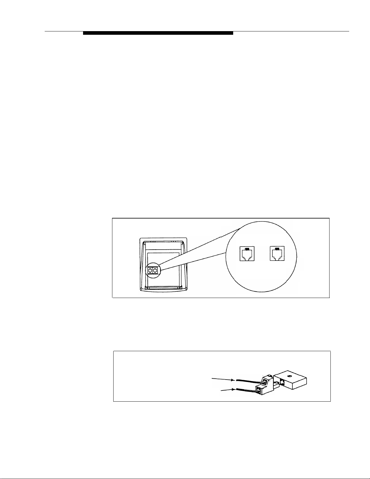
PARTNER-model system phones have a built-in auxiliary jack so you can
connect a standard device directly to the phone without using a bridging
adapter—see “Using a Direct Connection” below. If your system phone does
not have a built-in auxiliary jack or if you want to connect two standard devices
together, you must use a Lucent Technologies 267F2 Bridging Adapter—see
“Using a Bridging Adapter” below.
Using a Direct Connection
Figure 2 shows how to connect a standard device directly to a system phone,
using the phone’s built-in auxiliary jack. (Figure 2 is for illustration purposes
only; the placement of the jacks on your phone may differ.)
System Phone
Figure 2. Combination Extension Using Direct Connection
Using a Bridging Adapter
Figure 3 shows how to connect a system phone and a standard device or two
standard devices using a Lucent Technologies 267F2 Bridging Adapter.
Standard Device Only
System Phone or Standard Device
Figure 3. Combination Extension Using Bridging Adapter
Plug line into
jack labeled LINE
Plug standard device
into jack labeled
AUX
Lucent Technolologies
267F2
Adapter
Wall Jack
Installation Guidelines 7
Page 12
Installation Procedures
Before installing the system, be sure you read the safety
instructions on page ii.
WARNING:
There are no customer-serviceable components
inside the system modules or backplane. There are
hazardous voltages within that can cause severe or
fatal personal injury. DO NOT OPEN THE MODULES.
Installing the Control Unit and Modules
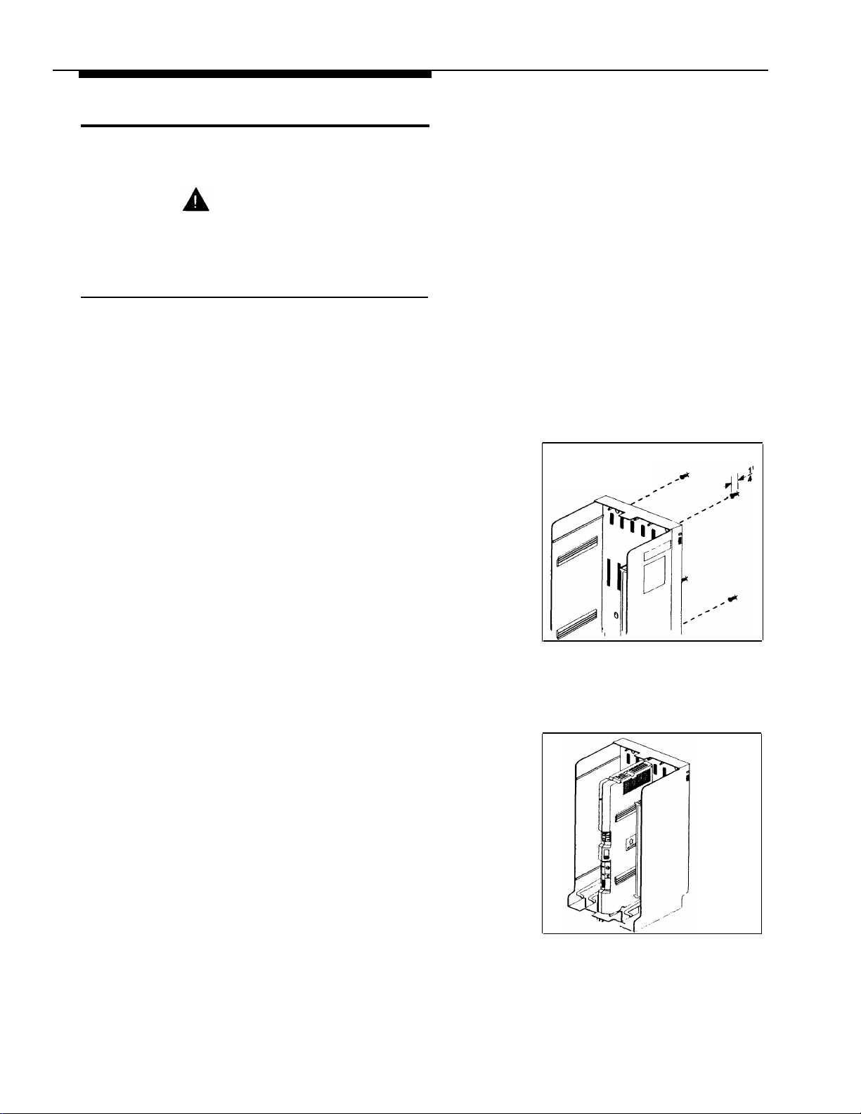
Install the control unit’s backplane within five feet (1.5
meters) of a properly grounded electrical outlet (not
controlled by a switch) and the network interface jacks.
In addition, when you mount the backplane on the wall,
leave at least six inches (15.2 cm) of clearance at the top
and sides, and two feet (0.6 meters) at the front and
bottom to ensure proper ventilation.
A)
1
Hold the backplane against the wall. (If you
are also installing the expansion carrier, plan
to install it to the right of the primary carrier,
leaving 6" to 24" (15.2 to 61 cm) between the
carriers.)
B)
Using the four screw keyholes in the backplane
as a template, mark screw locations on the
wall.
Backplane
2
Start four #12 screws, leaving the screw heads
C)
approximately 1/4" (.64 cm) away from the
wall.
D)
Slip the backplane onto the screws, then
tighten them.
If you are mounting the expansion carrier,
E)
repeat this step.
A)
Slide the primary processor module into the
center slot of the primary carrier. Push slowly
but firmly in the center of the module until the
module locks into place, and is attached to
the rear of the backplane. Do not force the
module. If it does not insert easily, remove
the module, clear any obstruction, and
reinsert it.
If you have an expansion carrier, slide the
B)
expansion processor module into its center
slot until the module locks into place.
8
Installation Procedures
Page 13
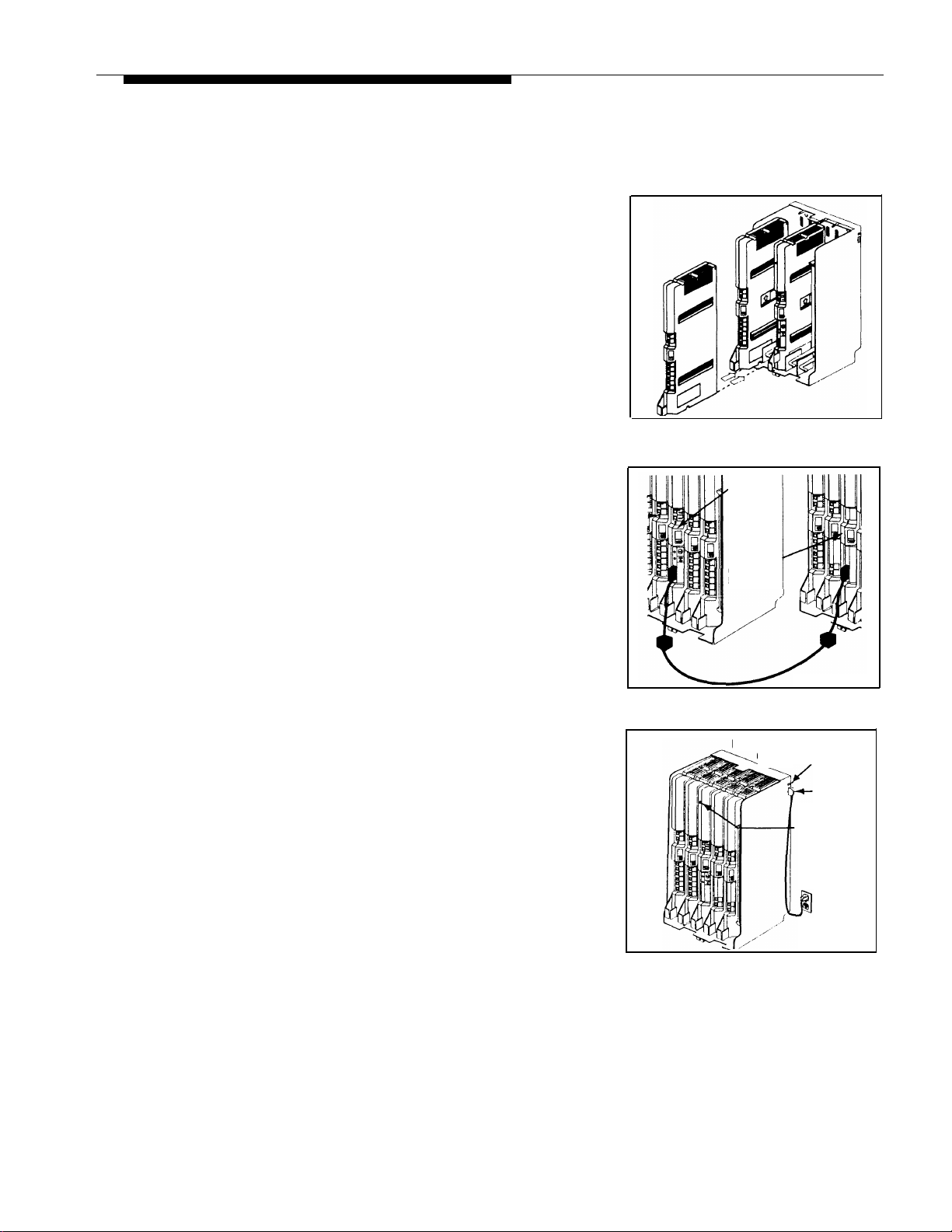
Before installing any modules, check to make
3
sure the clear, plastic cover has been removed from
the connector area on the rear of each module.
Slide the first 206 module into the leftmost
A)
4
slot of the primary carrier. (The system will
not work if a 206 module is not installed in this
slot.)
From left to right, install 206 modules, then
B)
any 400 (or 200) modules. The 400 modules
should always be to the right of all 206
modules, so the extensions will be numbered
consecutively. Also, you must install 206EC
and/or 400EC modules for any lines with
Caller ID service.
Do not force the modules. If a module does not
insert easily, remove it, clear any obstruction,
then reinsert it by pushing slowly, but firmly in
the center of the module.
If you installed both carriers, plug the ends
A)
5
of the expansion cable into the two processor
modules and tighten the screws.
Route both ends of the cable through the hooks
B)
on the fronts of the modules. The colored
plastic filters on the expansion cable should
rest just below the bottom edge of the carriers.
Primary
Processor
Module
Expansion
Processor
Module
6
Pull out the main circuit breakers on both
A)
carriers or move the on/off switch to the “off”
position (“O”), depending upon which
hardware configuration you have.
Attach one end of a #12 AWG or #14 AWG
B)
solid copper wire to the grounding screw on
the primary processor module. Note that the
length of the wire must not exceed 25 feet (7.6
meters).
Route the wire through the hook on the front of
C)
the module.
Attach the other end of the wire to an approved
D)
earth ground, such as building steel or a cold
water pipe.
If you installed both carriers, repeat Steps 6B–6D
E)
for the expansion processor module.
Main Circuit Breaker or
On/Off Switch
Power
Jack
Grounding
Screw
Installation Procedures
9
Page 14
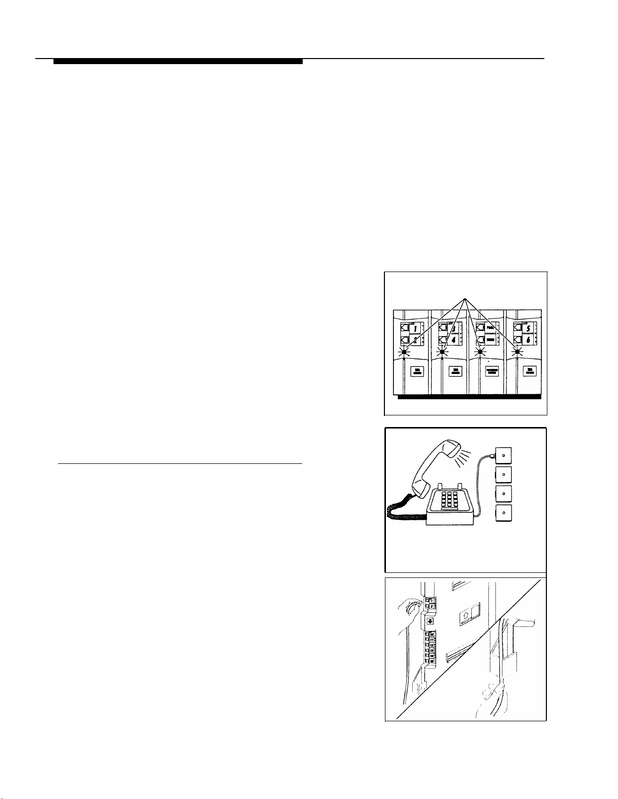
7
8
Press the power cord firmly into the power
A)
jack on the top right side of the primary
carrier’s backplane until it locks into place.
Plug the other end of the power cord into a
B)
properly grounded three-prong wall outlet not
controlled by a switch.
Repeat Steps 7A and 7B for the expansion
C)
carrier, plugging its cord into the same wall
outlet as the primary carrier’s cord.
To power up the control unit, push in the main
D)
circuit breaker on the expansion carrier first,
then push in the main circuit breaker on the
primary carrier, or move the on/off switch to
the “on” position (“l”).
Check all green lights on the fronts of the modules.
If all lights are lit, you can go to the next section;
otherwise:
If a single light is out, power down the control
A)
unit, reseat the module, then power up the
control unit.
If multiple lights are out, power down the
control unit, reseat the leftmost module that
has a light out, then power up the control unit.
Lights
If the lights are still out, call for support as
B)
instructed on the inside front cover of this
guide.
Connecting Lines and Extensions
If extensions are not wired to any modular jacks, call a
qualified service technician.
A)
1
2
Test for dial tone at the network interface jacks
before connecting outside lines to the control
unit. For the test, connect a standard phone
to the first network interface jack.
B)
Lift the handset and listen for dial tone. (If there
is no dial tone, contact your local telephone
company before continuing.)
Repeat for each network interface jack.
C)
A)
Connect line cords to the line jacks on 206 and
400 modules, starting with the top line jack on
the leftmost 206 module.
Route each cord through the hook on the front of
B)
the module.
Network
Interface
Jacks
555-1343
555-1344
555-1345
555-1346
10
Installation Procedures
Page 15
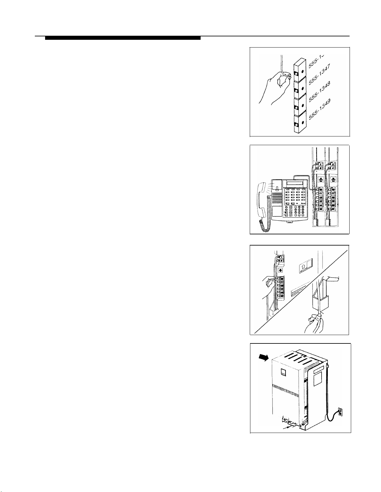
Connect the free end of each line cord to the
3
appropriate network interface jack.
4
5
Test the lines—plug a system phone into
A)
extension jack 10. Press the line buttons for
each outside line and listen for dial tone.
Repeat for extensions 16, 22, 28, 34, 40, 46
B)
and 52 (if available).
Connect modular telephone cords to 206
A)
module extension jacks, starting at the top
extension jack on the leftmost module.
Route each cord through the hook on the front
B)
of the module.
Connect the free end of each modular
C)
telephone cord to the modular connecting
blocks for system extensions.
Dress the wires. Gather the line and extension
D)
cords hanging below the hooks of the first two
modules and twist tie or wire wrap them.
Repeat for the remaining cords. Place each
bundle of wires in the indentations cut out of
the bottom edge of the backplanes.
6
Before installing the cover, make sure all modules
A)
are seated properly in the carrier. The cover
will not fit if the modules are not seated
properly.
To cover the modules, grasp the upper edges of
B)
the cover and hold it squarely over the control
unit. It is important to install the cover to keep
the modules dust-free and the system working
efficiently.
Place the cover over the modules and make sure
C)
it fits firmly in place.
D)
Insert the screw into the tab on the lower front of
the cover. Tighten the screw.
Screw
Installation Procedures
11
Page 16
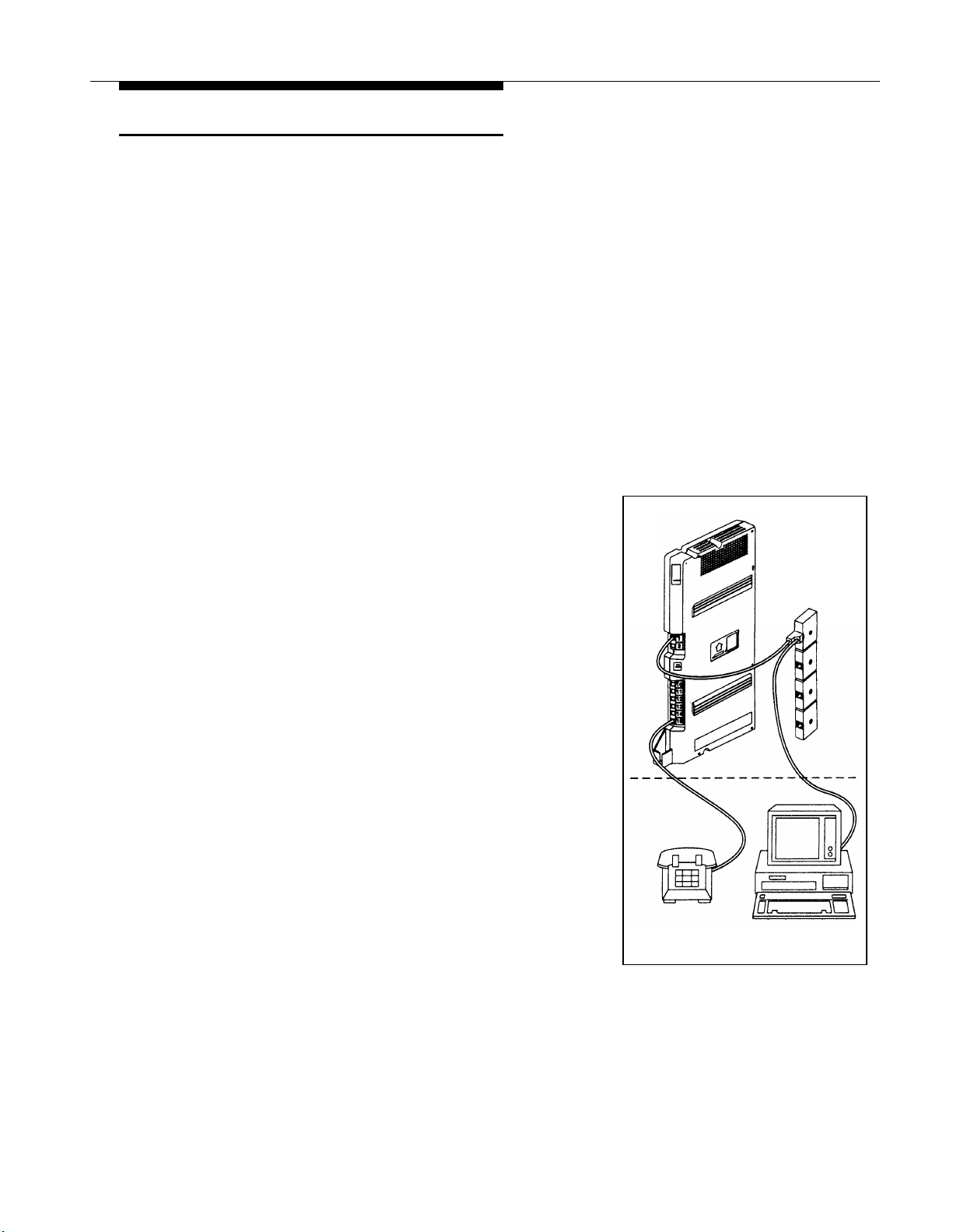
Connecting Caller ID Display Devices
The system provides multi-line Caller ID on system
display phones without having to install additional
devices. (See “Caller ID” in Chapter 5 of the PARTNER
II Communications System Programming and Use guide
for more information.) However, if you want to display or
process Caller ID information for other applications—for
example, on a PC that displays call records—you must
connect the devices as described here. First, you must
subscribe to Caller ID service from your local phone
company, then connect the Caller ID display device
directly to the line that supports Caller ID at the network
interface jack. Additionally, you must provide a separate
wiring run for the device to the appropriate location. To
process Caller ID information for multiple lines, you must
provide a separate device and a separate wiring run for
each line. To have additional wiring runs installed, call a
qualified technician.
1
Insert a Lucent Technologies 267F2 Bridging Adapter
into the network interface jack associated with the line
that has Caller ID service.
2
3
A)
Plug one end of a line cord into a jack in the
bridging adapter.
Plug the free end of the line cord into the
B)
appropriate line jack in the control unit.
Route the cord as you did for other line and
C)
extension cords.
Plug one end of a second line cord into the other
A)
jack in the bridging adapter.
B)
Plug the free end of the cord into the appropriate
modular connecting block in the equipment
room.
C)
Plug the Caller ID display device into the
additional modular jack provided at the
appropriate location.
D)
Place the Caller ID display device next to a
phone.
Make sure the Caller ID line is assigned to the
E)
extension where the Caller ID display device
is located. Refer to “Line Assignment (#301)”
in Chapter 5 of the PARTNER
Communications System Programming and
Use guide for programming instructions.
II
Phone
Network
Interface
Jacks
PC
12
Installation Procedures
Page 17
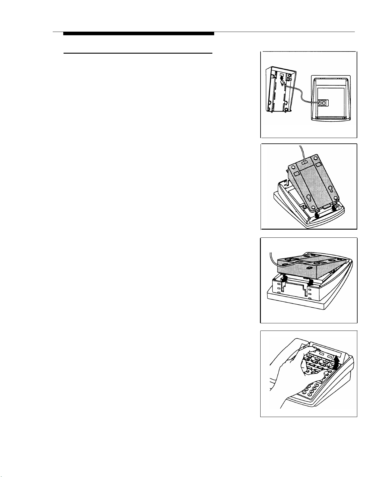
Assembling System Phones
All PARTNER-model system phones are shipped with a
stand for either desk mounting or wall mounting the
phone.
Desk Mounting
Gently place the phone upside down.
A)
1
Route the telephone cord through the hole in the
B)
top center of the stand.
Insert the tabs on the narrow end of the stand into
2
the slots on the inside bottom edge of the phone.
While pressing in the tabs that protrude from the
A)
3
wide end of the stand, lower the stand to the
phone.
Release the tabs to lock the stand into one of the
B)
three positions provided by the openings in
the back of the phone.
The height of the stand is adjustable to three
C)
positions: low, medium, and high. The phone
height can be adjusted by moving the locking
tabs to a different position.
4
A)
Turn the phone over.
Remove the plastic cover from the phone.
B)
Label the button sheet to show any.
programmed lines or button features, then
place the button sheet on the phone so the
holes fit over the buttons. Carefully replace
the plastic cover.
Adjust the swivel display to the desired angle
C)
(low, medium, or high).
D)
To access the User Instruction Cards, pull out
the tray located under the front of the phone.
Installation Procedures
13
Page 18
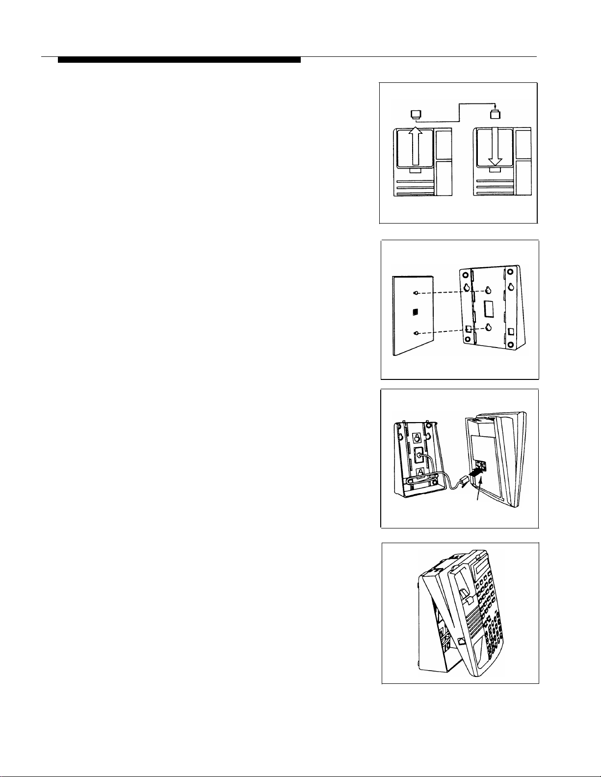
Wall Mounting
Wall mounting instructions apply only to PARTNERmodel phones. To wall mount an MDC 9000 cordless
phone, follow the instructions in the booklet provided with
the phone.
A)
1
B) Turn the phone upside down and remove the
Holding the stand with the wide edge down,
2
mount the stand on the wall plate using the
keyholes on the base of the stand. For proper
mounting, the wall plate must be a Lucent
Technologies 630B connecting block.
Reverse the plastic hook that sits in the
earpiece part of the handset cradle.
tray that holds the User Instruction cards:
press the tabs on both sides of the tray near
the pull out tab while you slide the tray straight
out.
A) Plug one end of the telephone cord into
3
the jack in the center of the wall plate.
B) Plug the other end of the telephone cord into
the LINE jack on the bottom of the telephone.
C)
Wrap any excess cord around the cord wrap
posts on the bottom inside of the stand.
A) To mount the phone on the stand, insert the
4
tabs on the top of the stand into the first set of
notches on the top edge of the phone.
B)
Make sure the telephone cord is neatly wrapped
inside the phone, then rotate the phone down
until the bottom edge snaps into position.
To
LINE
Jack
14
Installation Procedures
Page 19
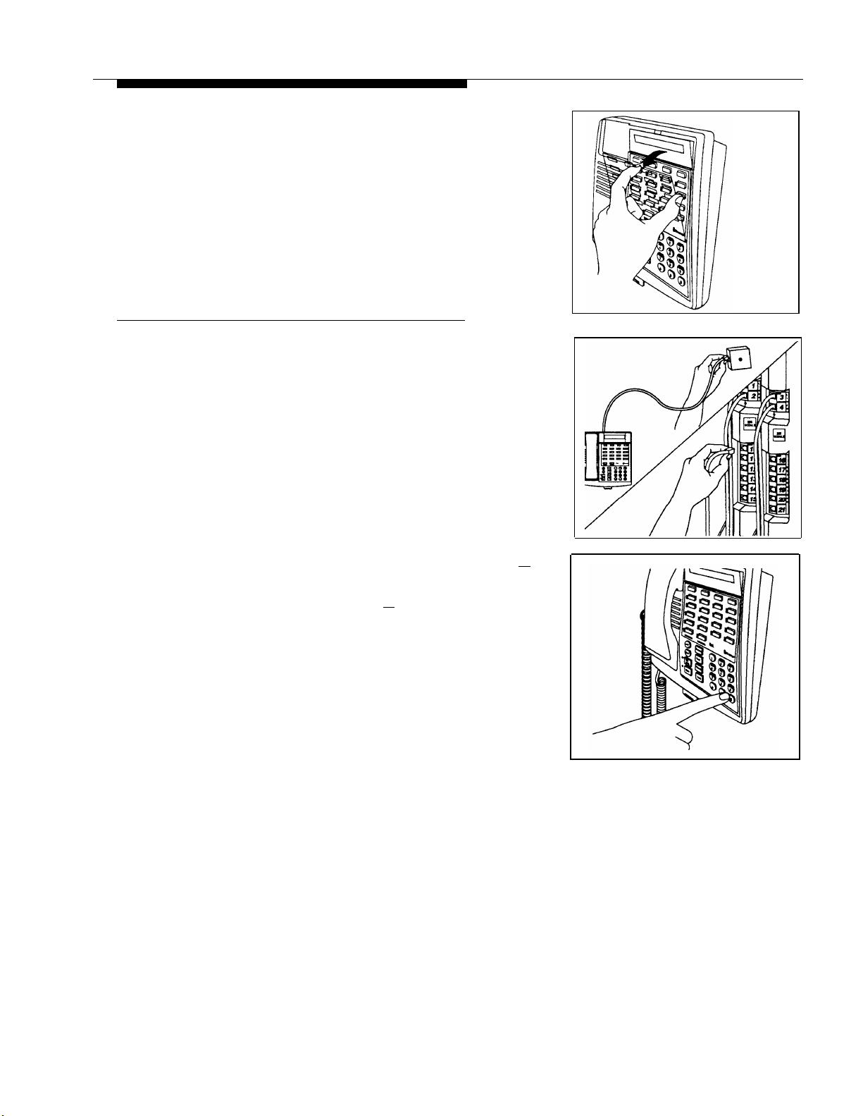
A)
5
Remove the plastic cover from the phone.
Label the button sheet to show any
programmed lines or button features, then
place the button sheet on the phone so the
holes fit over the buttons. Carefully replace
the plastic cover.
B Make sure the swivel display is set to the lowest
position.
Connecting and Testing Telephones
1 To connect a phone, plug the modular telephone
mounting cord into a modular wall jack or directly
into a 206 module extension jack. (If you are
connecting a standard phone and its mounting cord
is loose, use a Lucent Technologies D2R mounting
cord instead.)
To install two phones (or other devices) on a single
extension jack, see “Combination Extensions” earlier
in this guide.
2
Test the telephone for proper operation. To
A)
test the power and lights on a system phone:
while the phone is idle, press and hold the [
button for five seconds.
Before releasing the [
B)
All lights should light, the ringer should sound,
and (on system display phones only) a test
pattern should appear on the display. (If not,
call for support as instructed on the inside
front cover of this guide.)
Replace the handset; the phone is now in
C)
normal operating mode.
#
] button, lift the handset.
# ]
Installation Procedures
15
Page 20
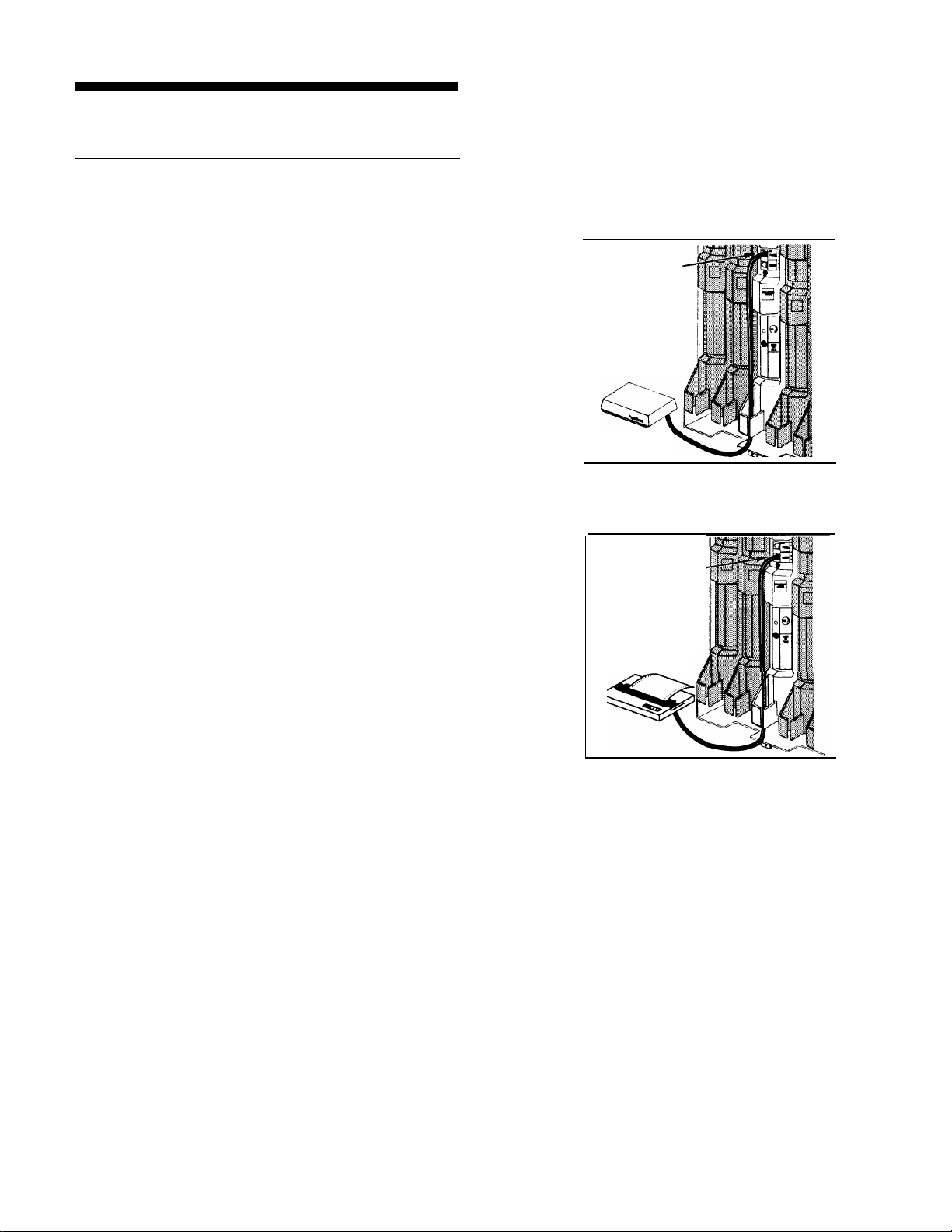
Connecting Paging, Call Reporting (SMDR), and Music-On-Hold Devices
Only steps for connection to the processor module are
provided here. See the manufacturer’s instructions for
more information on installing and using these devices.
Paging System
If you connect a paging system from a manufacturer
other than Lucent Technologies, a paging interface may
be required.
1 Insert the modular plug into the PAGE jack on the
primary processor module.
2
Route the cord as you did for line and extension
cords, then connect it to the paging system.
Call Reporting (SMDR) Printer
Insert one end of a D8W modular cord into the SMDR
1
jack on the primary processor module.
2
Plug the other end into a 355A adapter, then plug the
adapter into the printer’s RS-232C serial port.
PAGE Jack
Paging System
(optional)
SMDR Jack
Call Accounting
Terminal Printer
(optional)
16
Installation Procedures
Page 21
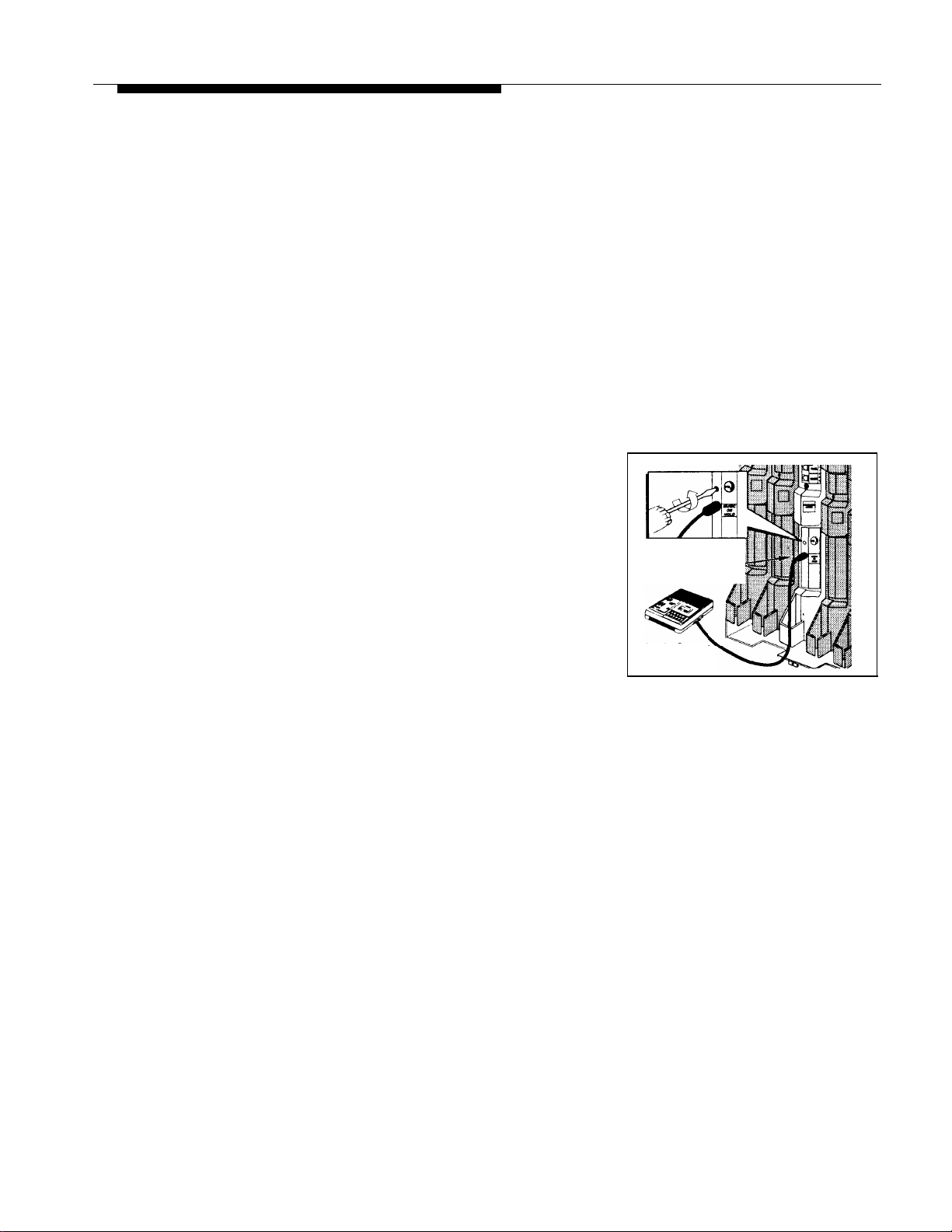
Music-on-Hold Audio Source
If you use equipment to broadcast certain copyrighted
music or material, including songs or other material from
radio broadcasts, you may be required to obtain the
permission of the copyright owner. One way to obtain
permission is to contact ASCAP, BMI, and/or similar
performing rights organizations, to obtain a license.
Lucent Technologies disclaims any liability arising out of
the failure to obtain such a license, if required.
For alternative (usually pre-licensed) sources of music to
use with this feature, you may wish to contact
Telephonetics International, Inc. at 1 800 446-5366. Or,
you can purchase a Magic On Hold system from Lucent
Technologies, which does not require you to obtain a
license.
First set the unit’s volume to the lowest setting.
1
Use a flathead screwdriver to turn the volume
control on the processor module counterclockwise
until it stops.
Insert an RCA phono plug into the MUSIC ON HOLD
2
jack on the primary processor module.
Route the cord as you did for line and extension
3
cords, then connect it to the audio source.
Volume Control
MUSIC ON HOLD
Jack
Place a call on hold and listen while adjusting the
4
volume, clockwise. If you do not hear music at any
setting, check “Music On Hold (#602)” in Chapter 5
of the PARTNER
Programming and Use guide.
II
Communications System
Audio Source
(optional)
Installation Procedures
17
Page 22
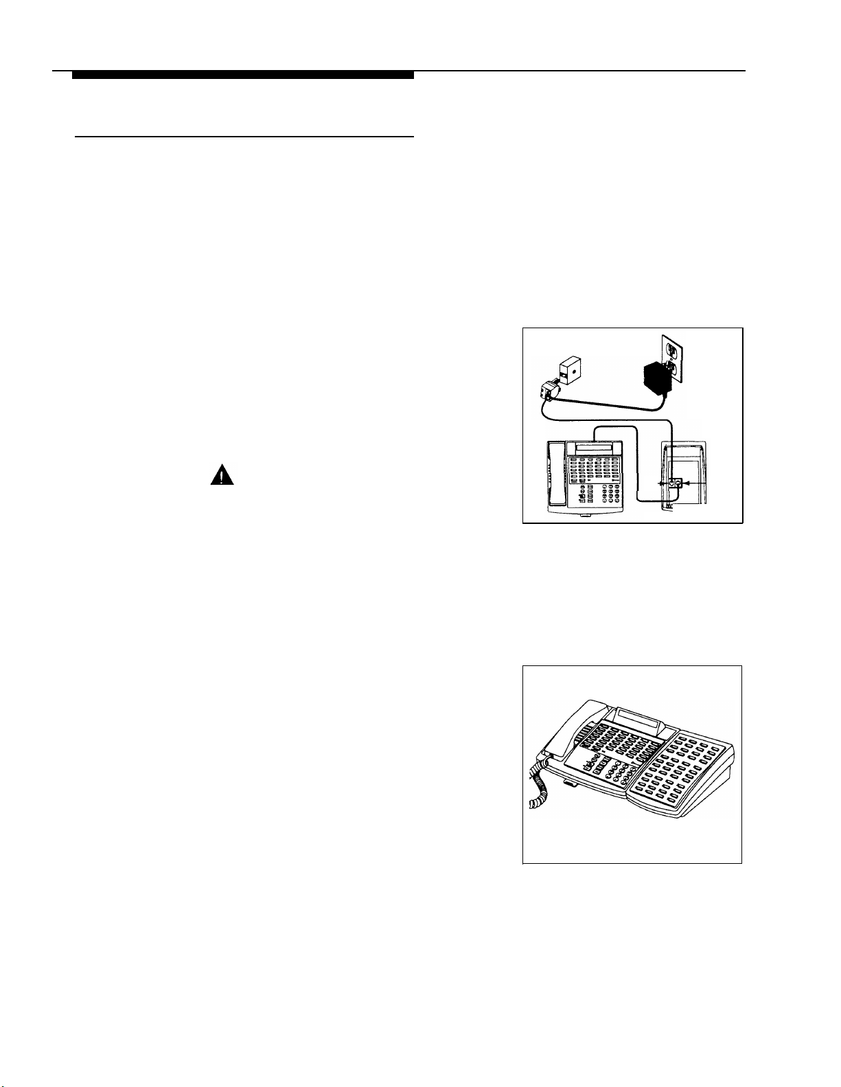
Connecting a PARTNER-CA48
Intercom Autodialer
The PARTNER-CA48 Intercom Autodialer is shipped with
an adapter, a D8W line cord, a power cord, a power unit,
and a button labeling sheet.
NOTE:
The PARTNER-CA48 Intercom Autodialer can be wall
mounted to work next to a wall-mounted system phone.
Plug the adapter into the wall jack.
1
2
A)
Plug one end of the D8W line cord into the J1 jack
on the adapter.
B)
Plug the other end of the D8w line cord into the
IN jack on the bottom of the autodialer.
3
A)
Plug the blue-tinted connector (labeled D8AC)
of the power cord into the jack on the power
unit.
Wall Jack
Power
Outlet
CAUTION:
Use only the power unit supplied with
the PARTNER-CA48 Intercom Autodialer.
B)
Plug the other end (clear tinted) of the power
cord into the J2 jack on the adapter.
Plug the power unit into an electrical outlet.
C)
4
Plug the phone’s modular telephone cord
into the OUT jack on the bottom of the
autodialer.
A)
5
IMPORTANT:
If you unplug the system phone that is connected to an
autodialer, you must reset the autodialer. To do so,
unplug the D8W line cord (connected to the IN jack on
the bottom of the autodialer) from the J1 jack on the
adapter, then plug it back in.
Arrange the autodialer on the desk next to the
phone.
Remove the plastic cover from the autodialer
B)
and label the button sheet with employee
names. Place the button sheet on the
autodialer, then carefully replace the plastic
cover.
Adjust the height of the autodialer to match the
C)
system phone.
IN
OUT
18
Installation Procedures
Page 23
Equipment Upgrades
Adding New Modules
WARNING:
Before starting, disconnect the power cord from the
power jack on the backplane.
A)
1
2
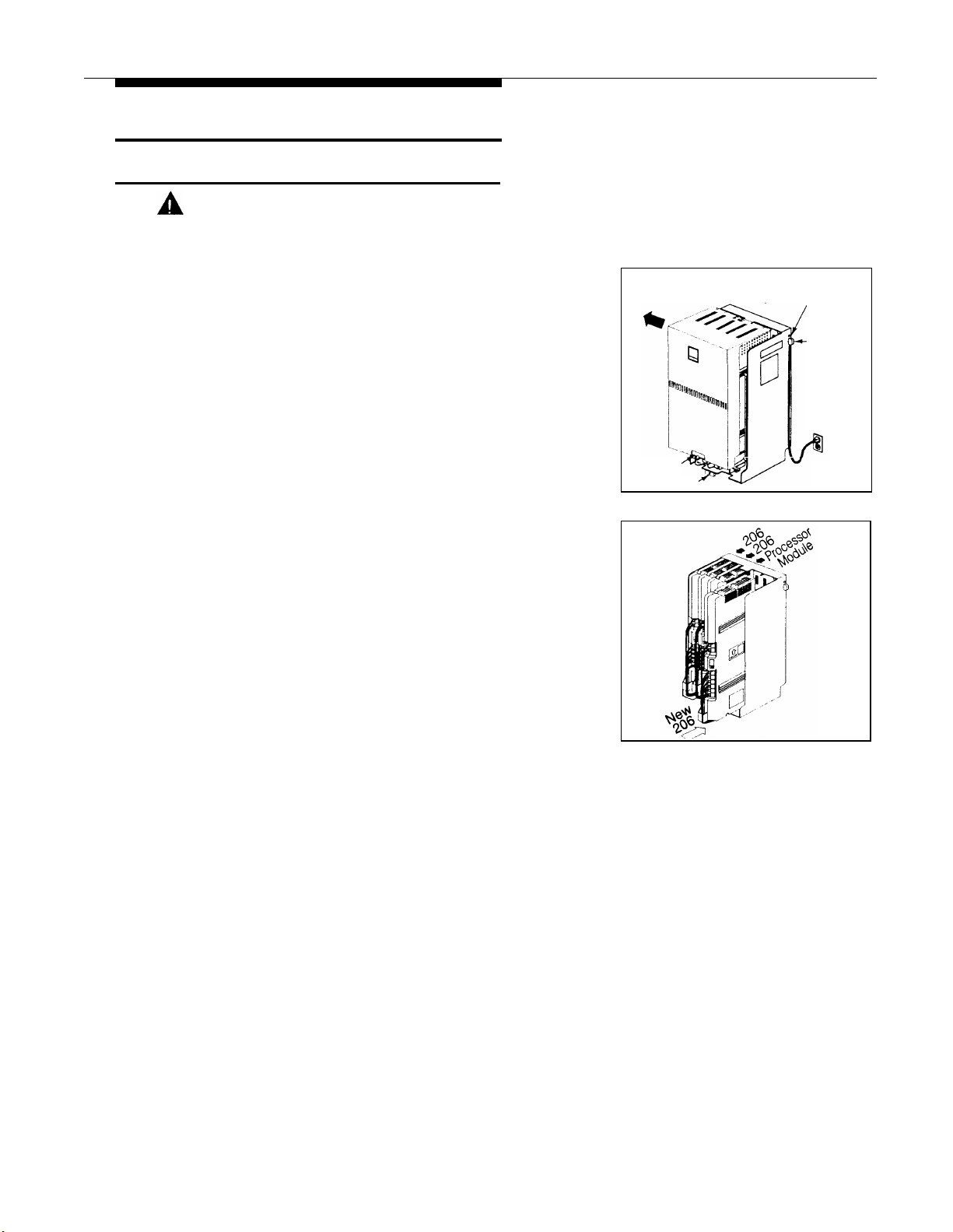
Pull out the main circuit breakers on both
carriers or move the on/off switch to the
“off” position (“O”), depending upon which
hardware configuration you have.
B)
To remove the cover, loosen the screw on the
lower front of the cover. Then place one hand
on the handle on the bottom front of the cover
and place your other hand on the top of the
cover.
Gently pull the cover up and away from the
C)
backplane—be careful not to break the tabs
that attach the cover to the backplane.
A)
Before you insert the new module, make sure
that all 400 (or 200) modules are installed to
the right of all 206 modules.
Push slowly but firmly in the center of the module
B)
until the module locks into place, and is
attached to the rear of the backplane. Do not
force the module. If the module does not
insert easily, remove it, clear any obstruction,
and reinsert it.
Handle
Screw
Main Circuit Breaker or
On/Off Switch
Power
Jack
3
See “Connecting Lines and Extensions” for
A)
instructions on connecting line and/or
extension jack cords to the new module.
B)
Reconnect the power cord.
To power up the control unit, push in the main
C)
circuit breakers, or move the on/off switch to
the “on” position (“l”).
Equipment Upgrades
19
Page 24
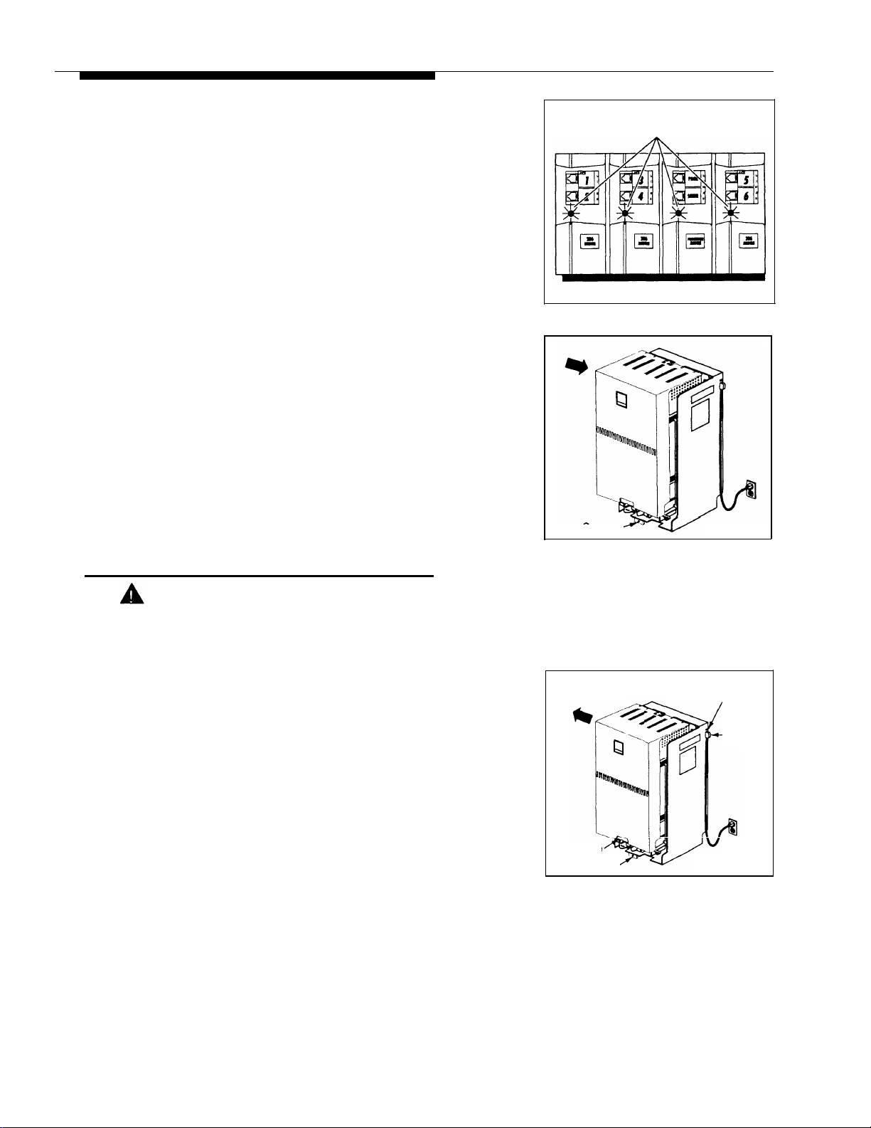
Check all green lights on the fronts of the modules.
4
If all the lights are lit, installation is complete;
otherwise:
If a single light is out, power down the control
A)
unit, reseat the module, then power up the
control unit.
If multiple lights are out, power down the
control unit, reseat the leftmost module that
has a light out, then power up the control unit.
If the lights are still out, call for support as
B)
instructed on the inside front cover of this
guide.
Lights
5
Before replacing the cover, make sure all
A)
modules are seated properly. The cover will
not fit if the modules are not seated properly.
To replace the cover, grasp it by its upper
B)
edges and hold it squarely over the control
unit.
C)
Place the cover over the modules and make
sure it fits firmly in place.
Tighten the screw on the lower front of the
D)
cover.
Replacing System Modules
WARNING:
Before starting, disconnect the power cord from the
power jack on the backplane.
A)
1
To power down the control unit, pull out the
the main circuit breakers on both carriers or
move the on/off switch to the “off” position (“O”),
depending upon which hardware configuration
you have.
To remove the cover, loosen the screw on the
B)
lower front of the cover. Then place one hand
on the handle on the bottom front of the cover
and place your other hand on the top of the
cover.
C)
Gently pull the cover up and away from the
backplane—be careful not to break the tabs
that attach the cover to the backplane.
Screw
Handle
Screw
Main Circuit Breaker or
On/Off Switch
Power
Jack
20
Equipment Upgrades
Page 25
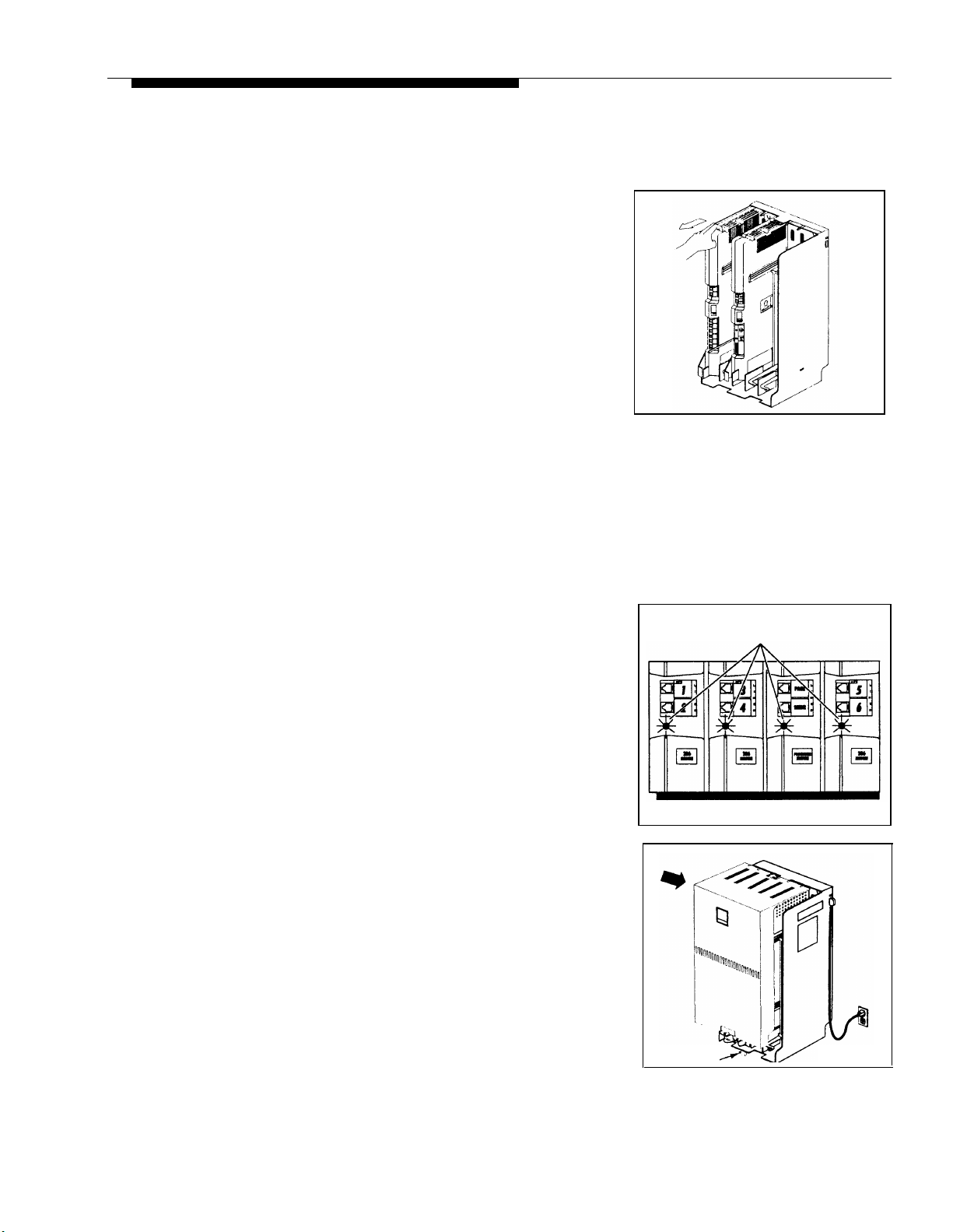
2
3
A)
Check the slack in the wires. If there is not
enough slack to remove the module without
pulling the line and extension cords free,
label and disconnect the wires before
continuing with Step 2B.
Place one hand on top of the module. With
B)
your other hand, grip the plastic bracket on
the bottom front of the module, and pull out
the old module.
To insert the replacement, push slowly but
C)
firmly in the center of the module until the
module locks into place, and is attached to
the rear of the backplane. Do not force the
module. If the module does not insert easily,
remove it, clear any obstruction, and reinsert it.
A)
Connect the line and extension cords one at a
time, making sure to place the correct cords
into their corresponding jacks on the new
module.
Reconnect the power cord.
B)
To power up the control unit, push in the main
C)
circuit breakers, or move the on/off switch to
the “on” position (“l”).
Check all green lights on the fronts of the modules. If
4
all the lights are lit, installation is complete; otherwise:
If a single light is out, power down the control
A)
unit, reseat the module, then power up the
control unit.
If multiple lights are out, power down the
control unit, reseat the leftmost module that
has a light out, then power up the control unit.
B)
If the lights are still out, call for support as
instructed on the inside front cover of this
guide.
Before replacing the cover, make sure all
A)
5
modules are seated properly. The cover will
not fit if the modules are not seated properly.
B)
To replace the cover, grasp it by its upper edges
and hold it squarely over the control unit.
C)
Place the cover over the modules and make sure
it fits firmly in place.
Tighten the screw on the lower front of the cover.
D)
Lights
Screw
Equipment Upgrades
21
Page 26

Specifications
Capacities
Dimensions
and Weights
(approx.)
System
■
12 outside lines via line jacks on
two 206 plus two 400 modules
■
24 extensions via extension jacks
on four 206 modules
■
1 loudspeaker paging system
via PAGE jack on processor
module
■
1 audio source via MUSIC ON
HOLD jack on processor module
(RCA phono plug required)
■
1 call reporting device via SMDR
206 Module
■
2 outside lines
■
6 extensions jack, total REN on jack not to
400 Module
4 outside lines
Extension Jack
■
Maximum 2 devices per extension
exceed 2.0* (System phone
REN is 0.0 (zero))
■
No more than one system phone
per jack
For programming, a system display
phone must be connected to
extension 10 or 11.
jack on processor module (355A/F
adapter required)
■
2 doorphones, using 2 extension
jacks
■
1 voice messaging system—
PARTNER MAIL VS, which
occupies a slot in the control unit or
PARTNER MAIL, which connects
to either 3 or 5 extension jacks.
■
Processor Module
■
206 module
■
400 module
■
Backplane & cover
■
PARTNER-34D phone 9.8"(D) x 3.75"(H) x 9.3"(W) or 24.9 x 9.5 x 23.6 cm
■
PARTNER-18D phone 9.8"(D) x 3.75"(H) x 7.9"(W) or 24.9 x 9.5 x 20.1 cm 2.4 Ibs or 1.1 kgs
■
PARTNER-18 phone
■
PARTNER-6 phone 9.8"(D) x 3.75"(H) x 6.1"(W) or 24.9 x 9.5 x 15.5 cm 1.9 Ibs or 0.9 kgs
■
MDC 9000 phone
■
MDW 9000 phone 9.75"(D) x 6"(H) x 4"(W) or 24.8 x 15.2 x 10.1 cm
■
PARTNER-CA48 9.8"(D) x 3.75"(H) x 6.1"(W) or 24.9 x 9.5 x 15.5 cm 1.5 Ibs or 0.7 kgs
11"(D) x 17"(H) x 1.5"(W) or 27.9 x 43.2 x 3.8 cm
11"(D) x 17"(H) x 1.5"(W) or 27.9 x 43.2 x 3.8 cm
11"(D) x 17"(H) x 1.5"(W) or 27.9 x 43.2 x 3.8 cm
12"(D) x 19"(H) x 11"(W) or 30.5 x 48.3 x 27.9 cm
9.8"(D) x 3.75"(H) x 7.9"(W) or 24.9 x 9.5 x 20.1 cm 2.3 Ibs or 1.0 kgs
9.4"(D) x 3.4"(H) x 7"(W) or 23.9 x 8.6 x 17.8 cm
4.0 Ibs or 1.8 kgs
4.5 Ibs or 2.0 kgs
4.0 Ibs or 1.8 kgs
5.5 Ibs or 2.5 kgs
2.7 lbs or 1.2 kgs
2.8 Ibs or 1.3 kgs
2.25 Ibs or 1.0 kgs
Autodialer
Switch Fabric
*
The two devices combined on an extension jack can be a system phone with a standard device, or two standard devices; DO NOT
■
Full digital, nonblocking
connect two system phones to the same extension jack. If a device lists two RENs, use the higher number when adding up RENs.
22
Specifications
Page 27

Electrica1
Specifications
Processor Module
Specifications
Extension Jack
Specifications
■
10 Watts (35 BTUs/hour) per 400 module, normal and maximum power consumption
■
65 Watts (225 BTUs/hour) per 206 module during normal operation
■
100 Watts (350 BTUs/hour) per 206 module during maximum power consumption
■
U.S., Canada, and other 110V countries: 4 Amps maximum current at full system capacity
(processor module and four 206 modules)
Countries using 220V: 2.2 Amps maximum current (processor module and four 206 modules)
■
4-day memory backup (96 hours)
■
68000 microprocessor, 128Kbytes RAM, 512Kbytes ROM
■
Ringing voltage: +5VDC, -140 VDC peak to peak; trapezoidal wave shaping
■
35- to 38-Volt talk battery
■
Ringing frequency: 20 Hz
PAGE Jack
Specifications
SMDR Output
Format
Environmental
Requirements—
Control Unit
Electrical
Requirements
■
Draws current on inner wire pair
■
Provides contact closure on outer wire pair
■
600 Ohm impedance
■
1200 baud
■
No parity
■
8 data bits
■
2 stop bits
■
XON/XOFF protocol
■
Carriage return
■
Line feeds
■
Mount on a wall at least 2 feet (0.6 meters) from the floor (wall mounting required)
■
Locate within 5 feet (1.5 meters) of the network interface jacks and a properly grounded
electrical outlet not controlled by a switch, using supplied 7-foot (2.1-meter) cords
■
For proper ventilation and easy replacement of modules, provide at least 6" (15.2cm) clearance
at the top and sides and 2 feet (0.6 meters) at the front and bottom of the control unit.
■
Operating temperature 32° to + 104°F (0° to +40°C), not in direct sunlight
■
Humidity 15%–90%, noncondensing
■
Locate in an area free of excess moisture, corrosive gases, dust, and chemicals
■
U.S. and Canada: 90–130 VAC, 50–60 Hz, 3-prong outlet separate ground, separately fused at
15 Amps
Other countries: 90–264 VAC, fused at 10 Amps
■
Outlet must not be controlled by an on/off switch
■
Grounding to comply with Underwriters Laboratories (UL) 1459:
An insulated grounding conductor that is not smaller in size and equivalent in insulation
A.
material and thickness to the grounded and ungrounded branch circuit supply conductors,
except that it is green with or without one or more yellow stripes, is to be installed as part of the
circuit that supplies the product or system.
The grounding conductor mentioned in item A is to be connected to ground at the service
B.
equipment.
The attachment-plug receptacles in the vicinity of the product or system are all to be of a
C.
grounding type, and the grounding conductors serving these receptacles are to be connected
to earth ground at the service equipment.
Specifications
23
Page 28

Requirements for
Out-of-Building
Extensions
■
Installation of a telephone or other standard (tip/ring) device in another building requires the
following In-Range Out-of-Building (IROB) protectors to protect the control unit and device from
electrical surges:
■
System phone: two Lucent Technologies IROB protectors
■
Standard device: one Lucent Technologies IROB protector plus one carbon block protector
Wiring
Safety
Requirements
Government
Approvals and
Local Phone
Company
Information
■
System phones: Lucent Technologies SYSTIMAX® Bulk Nonplenum (DIW) cable, Lucent
Technologies SYSTIMAX Bulk Plenum (HALAR/HALAR) cable, or at least 2-pair (4-wire) star
(“home run” not “loop”)
■
Other standard telecommunications equipment (single-line phones, fax machines, answering
machines, etc.): 1-pair (2-wire) mounting cords (Lucent Technologies D2R mounting cords
recommended)
■
Bridging adapter: Lucent Technologies 267F2
■
Range: 1,000 feet (305 meters) for system phones; 3,000 feet (915 meters) for standard devices
■
U.S.: Meets UL 1459 Issue 2
■
Canada: Meets CSA C22.2, 225
■
All other countries: Meets IEC950 Second Edition and EN60950 Second Edition
■
U.S.:
FCC Part 68
FCC registration number (U.S.): AS5 USA-61630-KF-E
FCC Part 15 Class A
REN (outside line jack): 0.9A per line jack
Jack type: RJ11 C
Loop start lines
■
Canada: IC CP01, Issue 7
IC registration number (Canada): 230 3756A
IC CS03, Issues 6 & 7
Load Number = 7
Loop start lines
24
Specifications
Page 29

Lucent Technologies 518-455-333
Comcode 107879223
Issue 2
August 1996
 Loading...