

Page 1

PacketStar®
PSAX 1250 Multiservice Media Gateway
User Guide
Issue 2, September 2002
System Software Release 8.0.0
Doc. No.: 255-700-247
Page 2

Copyright © 2002 by Lucent Technologies. All rights reserved.
For trademark, regulatory compliance, and related legal information, see
the "Legal Notices, Safety, and Regulatory Information" section.
Page 3

Legal Notices, Safety, and Regulatory
Copyright
Trademarks
Information
Copyright © 2002 by Lucent Technologies. All rights reserved.
This material is protected by the copyright laws of the United States and
other countries. It may not be reproduced, distributed, or altered in any fashion by any entity (either internal or external to Lucent Technologies), except
in accordance with applicab le agreements , contracts o r licensing, wi thout the
express written consent of the originating organization and the business
management owner of the material.
This document was prepared by the Information Des ign and Development
T eam of Lucent Technologies, PacketStar PSAX product s. Offi ces ar e locate d in
Landover, Maryland, USA.
PacketStar, AQueView, Lucent, Lucent Technologies, and the Lucent Technologies logo are register ed tradema rks of Lucent Technol ogies in the USA. Other
product and brand names mentioned in this guide are trademarks or registered trademarks of their respective owners.
Notices
The information in this document is for informational use only, is subject to
change without notice, and should not be construed as a commitment by
Lucent Technologies, Inc. This document is without warranty of any kind,
either expressed or implied. Lucent Technologies, Inc. assumes no responsibility for any errors, inaccuracies, or omissions. Neither is any liability
assumed for damages resulting from the use of the information or instructions contained herein. Lucent Technologies, Inc. is not responsible for any
damage or loss to your data or equipment resulting either directly or indirectly from use of this document.
Warranty Information
Software and Hardware Limited Warranties
Lucent Technologies provides a 90-day limited software warranty, and a oneyear limited hardware warranty on this product. Refer to the Software License
and Limited Warranty Agreement and the Lucent Technologies InterNetworking Systems Global Warranty that accompanied your package for more information.
PacketStar® PSAX 1250 Multiservice Media Gateway User Guide, Issue 2 Release 8.0.0
255-700-247 iii
Page 4

Legal Notices, Safety, and Regulatory Information
Warranty Information
Warr anty Warnings
!
WARNING:
Modifying or tampering with PSAX chassis components will void your
warranty. Any modification to this equipment not expressly authorized
by Lucent Technologies will void your granted authority to operate such
equipment.
!
WARNING:
Air filters in the PSAX chassis should be inspected for accumulated dust
and replaced as needed. At a minimum, quarterly inspection of the air filter is recommended. However, depending on the environmental quality
of the facility more or less frequent inspections may be warranted.
Equipment failure due to inadequate maintenance will void your equipment warranty.
!
WARNING:
Use only air filters supplied by Lucent Technologies in your PSAX chassis.
Use of other air filters will void your equipment warranty.
!
WARNING:
Using excessive force to install modules that causes damage to the module and/or the chassis will void your equipment warranty.
!
WARNING:
Shipping the chassis with any modules installed may cause damage to
the chassis and the modules. Damage to any of the components in the
system resulting from improper shipping methods will void your warranty.
!
WARNING:
Proper ventilation above and below the chassis must be maintained to
prevent overheating. Air vents in the PSAX chassis must be regularly
inspected and cleared of dust and blockage. Equipment failure associated with improper maintenance or suspected failure to adhere to
proper ventilation procedures will void your warranty.
!
WARNING:
If a PSAX 1250 Fan Tray or heat deflector is not installed above the
PSAX 1250 chassis, a minimum of 4.45 cm (1.75 in.) clearance above the
chassis must be maintained for adequate airflow to prevent equipment
failure due to overheating. Failure to provide this clearance between the
chassis and any other device/structure will void your warranty.
PacketStar® PSAX 1250 Multiservice Media Gateway User Guide, Issue 2 Release 8.0.0
iv 255-700-247
Page 5

Legal Notices, Safety, and Regulatory Information
Regulatory Standards Compliance
The PacketStar PSAX 1250 Multiservice Media Gateway , models 20S00 (19 in.
chassis with AC or DC power) and 20S10 (23 in. chassis with DC power), is
compliant with the listed Safety, Electromagnetic Compatibility (EMC) and
Telecommunications standards. Applicable statements appear in the next
subsection.
Safety
• UL 1950, Third Edition (USA)
• CSA 22.2 No. 950, Third Edition (Canada)
• EN 60950:1992+A1:1993+A2:1993+A3:1995+A4:1997 +A11:1997
(Europe) (-48 V dc and 220 V ac)
• S-Mark (Argentina)
• NOM (Mexico)
• AS/NZS 3260:1993+S1:1996 (Australia/New Zealand)
• ACA TS 001:1997 (Australia)
• CB-Scheme – IEC 60950:1991+A1:1992+A2:1993+A3:1995+A4:1996
(International)
Regulatory Standard s Compli an c e
Electromagnetic Compatibility
• FCC Part 15 Class A (USA)
• ICES-003, Issue 3:1998 Class A/NMB-003 Version 3:1998 classe A
(Canada)
• EN 55022:1998 Class A (Europe) (-48 V dc and 220 Vac)
• EN 55024:1998 (Europe) (-48 V dc and 220 V ac)
• EN 300 386-2:1997 (Europe) (-48 V dc and 220 V ac)
• EN 61000-3-2:2000 (Europe)
• EN 61000-3-3:1995 (Europe)
• AS/NZS 3548:1995+A1:1997+A2:1997 (Australia/New Zealand)
• VCCI Class A (Japan)
• CISPR 22:1993+A1:1995+A2:1996 Class A (International), with AC power
only
• CISPR 22:1997 Class A (International) (-48 V dc and 220 V ac)
• CISPR 24:1997 Class A (International) (-48 V dc and 220 V ac)
Telecommunications
• FCC Part 68 (USA)
• CS-03 Issue 8/SH-03 Version 8 (Canada)
• ETSI TBR 12:1993+A1:1996 (Europe) (-48 V dc and 220 Vac)
• ETSI TBR 13:1996 (Europe) (-48 V dc and 220 V ac)
• ETSI TBR 24:1997 (Europe) (-48 V dc and 220 V ac)
• TS 016:1997 (Aust ralia )
• TS 026:1997 (Aust ralia )
• JATE (Japan)
PacketStar® PSAX 1250 Multiservice Media Gateway User Guide, Issue 2 Release 8.0.0
255-700-247 v
Page 6

Legal Notices, Safety, and Regulatory Information
Regulatory Statements
Regulatory Statements
USA Regulatory State ments
FCC Part 15 This equipment has been tested and found to comply with the limits for a
Class A digital device, pursuant to Part 15 of the FCC rules. These limits are
designed to provide reasonable protection against harmful interference when
the equipment is operated in a commercial environment. This equipment
generates, uses, and can radiate radio frequency energy, and, if not installed
and used in accordance with this guide, may cause harmful interference to
radio communications. Operation of this equipment in a residential area is
likely to cause harmful interference; in this case, you would be required to
correct the interfer ence at your own expense.
All cables used to connect to peripherals must be shielded and grounded.
Operation with cables, connected to peripherals, that are not shielded and
grounded may result in interference to radio and television reception.
The user is cautioned that any changes or modifications not expressly
approved by the party responsible for compliance could void the user’s
authority to operate the equipment.
FCC Part 68 This equipment complies with Part 68 of the FCC rules. On the back of the
PSAX chassis is a label that contains the FCC registration number, in addition
to other information. You must provide this information to the telephone
company, if they request it. The FCC requires Lucent Technologies to provide
you with the following information:
1. This equipment has digital service interface capabilities using RJ-48C and
RJ-48H connectors. The facility interface codes with which this equipment complies for digital services are as follows: 04DU9-BN, 04DU9-DN,
04DU9-1KN, and 04DU9-1SN. This equipment has loop start interface
capabilities using an RJ-11C connector. The facility interface code with
which this equipment complies for service is 02LS2. The service order
codes for this equipment are 6.0F for the T1 interface and 9.0Y for the
loop start interface.
2. An FCC-compliant telephone network interface jack is built into this
equipment and is compatible with interconnections that are Part 68 compliant.
3. The REN for the Voice 2-Wire Office module when used in this equipment is 0.7B.
4. If this equipment causes harm to the telephone network, the telephone
company will notify you in advance that temporary discontinuance of
service might be required. But if advance notice is not practical, the telephone company will notify you as soon as possible. Also, you will be
advised of your right to file a complaint with the FCC if you believe this
is necessary.
PacketStar® PSAX 1250 Multiservice Media Gateway User Guide, Issue 2 Release 8.0.0
vi 255-700-247
Page 7

Legal Notices, Safety, and Regulatory Information
Regulatory Statements
5. The telephone company might make changes in its facilities, equipment,
operations, or procedures that could affect the operation of this equipment. If this happens, the telephone company will provide advance
notice for you to make necessary mo difications to maintain uninterrupted service.
6. If you experience trouble with this equipment, or need repairs or warranty information, please refer to the Lucent Technologies InterNetworking
Systems G lobal Warranty that accompanied your PSAX product shipment
for instructions on obtaining technical support in your area.
If this equipment is causing harm to the telephone network, the telephone company might request that you disconnect the equipment until
the problem is resolved.
7. This equipment has no user-serviceable parts.
This equipment cannot be used on public coin telephone service provided by
the telephone company. Connection to party line service is subject to state
tariffs. Contact your state public utility commission, public service commission, or corporation commission for information.
Canadian Regulatory Statements
ICES-003 This Class A digital apparatus complies with Canadian ICES-003.
NMB-003 Cet appareil numérique de la classe A est conforme à la norme NMB-003 du
Canada.
CS-03 Issue 8 NOTICE: This equipment meets applicable Industry Canada Termi-
nal Equipment Tec hnica l Speci fica tions. This is confir med by th e reg istration number. The abbreviation, IC, before the registration number signifies that registration was performed based on a Declaration
of Conformity indicating that Industry Canada technical specifications were met. It does not imply that Industry Canada approved the
equipment.
The Ringer Equivalence Number (REN) assigned to the Voice 2-Wire Office
module denotes the percentage of the total load to be connected to a telephone loop, which is used by the device, to prevent overloading. The termination on a loop may consist of any combination of devices subject only to
the requirement that the total of the REN of all devices does not exceed 5.
The REN for the Voice 2-Wire Office module when used in the PSAX system
is 0.7B.
SH-03 Version 8 A VIS: Le présent matériel est conforme aux spécifications techniques
d’Industrie Canada applicables au matériel terminal. Cette conformité est confirmée par le numéro d’enregistrement. Le sigle, IC,
placé devant le numéro d’enregistrement, signifie que l’enregistrement s’est effectué conformément à une déclaration de conformité
PacketStar® PSAX 1250 Multiservice Media Gateway User Guide, Issue 2 Release 8.0.0
255-700-247 vii
Page 8

Legal Notices, Safety, and Regulatory Information
Regulatory Statements
et indique que les spécifications techniques d’Industrie Canada ont
été respectées. Il n’implique pas qu’Industrie Canada a approuvé le
matériel.
Le nombre équivalent de sonnerie (REN) attr ibué au module central bifilaire
(Voice 2-Wire Office) correspond au pourcentage de la charge totale à connecter à un circuit téléphonique bifilaire; il est utilisé par l’appareil pour
prévenir la surcharge. Le circuit peut être terminé par n’importe quelle combinaison d’appareils, à la seule condition que le total des REN de ces derniers
ne dépasse pas cinq.
Lorsqu’il est utilisé dans le système PSAX, le module central bifilaire possède
un REN de 0,7 B.
European Union Regulatory Statement
CE Marking Hereby, Lucent Technologies declares that the PacketStar PSAX 1000
(-48 V dc and 220 Vac), PSAX 1250 (-48 V dc and 220 Vac), PSAX 2300,
and PSAX 4500 Multiservice Media Gateways are in compliance with the
essential requirements and other relevant provisions of the following Council
Directives:
• Low Voltage 72/23/EEC
• Electromagnetic Compatibility (EMC) 89/336/EEC
• Radio Equipment and Telecommunications Ter minal Equipment
1999/5/EC
The Lucent PacketStar PSAX Multiservice Media Gateways deployed in the
European Economic Area (EEA) are intended for connection to E1, E3,
STM-1, and STM-4c networks. The EC Declarations of Conformity may be
viewed or printed at the following public-access Internet site:
http://www.lucent.com/ins/doclibrary
EU-regulativer
CE-mærkning Lucent Technologies erklærer hermed at PacketStar PSAX 1000 (-48 V dc og
220 v vekselstrøm), PSAX 1250 (-48 V dc og 220 v vekselstrøm), PSAX 2300,
and PSAX 4500 Multiservice Media Gateways overholder kravene i følgende
EU-direktiver:
• Lavspændingsdirektivet 72/23/EEC
• EMC-direktivet 89/336/EEC
• Direktivet om radio og teleterminaludstyr 1999/5/EC
Lucent PacketStar PSAX Multiservice Media Gateways, anvendt i EØS
(Europæiske Økonomiske Samarbejde) skal forbindes med E1, E3 STM-1 og
STM-4c netværk. EU-overensstemmelseserklæringen er at finde på følgende
internet side hvorfr a den også kan udskrive s:
http://www.lucent.com/ins/doclibrary
PacketStar® PSAX 1250 Multiservice Media Gateway User Guide, Issue 2 Release 8.0.0
viii 255-700-247
Page 9

Legal Notices, Safety, and Regulatory Information
Regulatory Statements
Behördliche Standard-CE-Kennzeichnung für die Europäische Gemeinschaft
CE-Markierung Hiermit erklärt Lucent Technologies, dass die PacketStar PSAX 1000
(-48 V DC und 220 V~), PSAX 1250 (-48 V DC und 220 V~), PSAX 2300,
und PSAX 4500 Multiservice Media Gateways die notwendigen Anforderungen und anderen relevanten Vorschriften der folgenden Council-Direktiven
einhalten:
• Niederspannungsdirektive 72/23/EEC
• Elektromagnetische Verträglichkeit (EMC) 89/336/EEC
• Funkgeräte und Funkverkehr-Endeinrichtungen 1 999/5/EC
Die Lucent PacketStar PSAX Multiservice Media Gateways, die in der
Europäischen Gemeinschaft im Einsatz stehen, dienen zum Anschluss an folgende Netztypen: E1, E3, STM-1 und STM-4c. Die Konformitätserklärung für
die Europäische Gemeinschaft kann auf folgendem, öffentlich zugänglichem
Internet-Site eingesehen oder ausgedruckt werden:
http://www.lucent.com/ins/doclibrary
¥²³²·¸¯¢q¶¢¸½´³¸¬»}½¶º´¥¿¯»²º·¬»
tÄ¥²·¬&( ©¸³´¥¶¢²¬/XFHQW7HFKQRORJLHV¨¬°µ²©¢¸¸¥PacketStarPSAX1000 (-48Vdc
¯¥9DF), PSAX1250 (
VHUYLFH0HGLD*DWHZD\V©²¥¶±³²¡¾³²¸¥±©¸»¦¥·¯»¥´¥¸·©»¯¥°³´»
·¼©¸¯»¨¥¸®©»¸º²¨¬«µ²¸³½t½±¦³½°¡³½
• ¥±¬°¸·¬(2.
• +°©¯¸¶³±¥«²¬¸¯·½±¦¥¸¢¸¬¸¥(0&(2.)
• ¥¨³ªº²¯¢»©®³´°·±¢»¯¥}®³´°·±¢»¸©¶±¥¸¯³¤¸¬°©´¯³²º²µ²(.
¥/XFHQW3DFNHW6WDU36$;0XOWLVHUYLFH0HGLD*DWHZD\V´³½¼³½²¸³´³¹©¸¬¹©¡
·¸³²}½¶º´¥¿¯¢¯³²³±¯¢µ¶³}}y´¶³³¶¡¾³²¸¥«¥·¤²¨©·¬±©¸¥¨¡¯¸½¥
((670¯¥670F m¬°µ·©»}²¥¶±¢²·¬»¸¬»}±´³¶³¤²²¥
´¶³¦°¬¹³¤²²¥¸½´º¹³¤²¥´¢¸¬²´¥¶¥¯¸º´¶³·¸·¸³¯³²¢¸³´³¹©·¡¥¸³½
²¸©¶²©¸
KWWSZZZOXFHQWFRPLQVGRFOLEUDU\
-48Vdc¯ ¥ 9DF), PSAX2300, ¯¥ PSAX0XOWL
Euroopan unionin sääntelystandardi
CE-merkintä Lucent Technologies vakuuttaa täten, että PacketStar PSAX 1000 (-48 V dc ja
220 V vaihtovirtaa), PSAX 1250 (-48 V dc ja 220 V vaihtovirtaa), PSAX 2300,
ja PSAX 4500 Multiservice Media Gatewayt täyttävät seuraavien neuvoston
direktiivien keskeiset vaatimukset ja asiaankuuluvat määräykset:
• Pienjännite 72/23/EY
• Sähkömagneettinen yhteensopivuus (EMC) 89/336/EY
• Radiolaitteet ja telepäätelaitteet 1999/5/EY
PacketStar® PSAX 1250 Multiservice Media Gateway User Guide, Issue 2 Release 8.0.0
255-700-247 ix
Page 10

Legal Notices, Safety, and Regulatory Information
Regulatory Statements
Lucent PacketStar PSAX Multiservice Media Gatewayt, joita käytetään
Euroopan talousalueella, on tarkoitettu liitettäväksi E1-, E3-, STM-1- ja
STM-4c-verkkoihin. EU:n vaatimustenmukaisuusvakuutus voidaan nähdä
tai tulostaa seuraavalta julkiselta Internet-sivulta:
http://www.lucent.com/ins/doclibrary
Norme réglementaire de l’Union européenne
Label CE Lucent Technologies déclare en ceci que les passerelles de média multiser-
vices PacketStar PSAX 1000 (-48 V c.c. et 220 V ca), PSAX 1250 (-48 V c.c. et
220 V ca), PSAX 2300, et PSAX 4500 sont conformes aux exigences essentielles et autres dispositions pertinentes des directives suivantes du Conseil:
• Basse tensio n 72/23/ CEE
• Compatibilité électromagnétique (CEM) 89/336/CEE
• Matériel radio et terminaux de télécommunications 1999/5/CE
Les passerelles de média multiservices PacketStar PSAX de Lucent, commercialisées dans l’Espace économique européen sont destinées aux connexions
à des réseaux E1, E3, STM-1 et STM-4c. Les déclarations de conformité CE
peuvent être consultées ou imprimées à partir du s ite In tern et d’accès public:
http://www.lucent.com/ins/doclibrary
Normativa dell’Unione Europea
Apposizione del
marchio CE
La Lucent Technologies dichiara che i gateway multiservizio PacketStar
PSAX 1000 (-48 V dc e 220 V c.a.), PSAX 1250 (-48 V dc e 220 V c.a.),
PSAX 2300, e PSAX 4500, rispondono ai requisiti essenziali ed ad altre
norme rilevanti delle seguenti direttive del Consiglio:
• Direttiva 72/23/CEE “Basse tensioni”
• Direttiva 89/336/CEE sulla compatibilità elettromagnetica
• Direttiva 1999/5/CE riguardante le apparecchiature radio e le apparecchia-
ture terminali di telecomunicazione
I gateway multiservizio Lucent PacketStar PSAX impiegati nell’area economica europea (EEA), sono concepiti per il collegamento con reti E1, E3, STM-1
e STM-4c. Le dichiarazioni di conformità CE possono essere stampate o
visionate presso il seguente sito Internet di pubblico accesso:
http://www.lucent.com/ins/doclibrary
Norm van de Europese Unie
CE-markering Lucent Technologies verklaart hierbij dat de PacketStar PSAX 1000 (-48 V dc
en 220V wisselstroom), PSAX 1250 (-48 V dc en 220V wisselstroom),
PSAX 2300, en PSAX 4500 Multi Service Media Gateways voldoen aan de
essentiële vereisten en andere relevante bepalingen van de volgende Richtlijnen van de Raad:
• Laagspanning 72/23/EEG
PacketStar® PSAX 1250 Multiservice Media Gateway User Guide, Issue 2 Release 8.0.0
x 255-700-247
Page 11

Legal Notices, Safety, and Regulatory Information
Regulatory Statements
• Elektromagnetische compatibiliteit (EMC) 89/336/EEG
• Radioapparatuur en telecommunicatie-eindapparatuur 1999/5/EG
De Lucent PacketStar PSAX Multi Service Media Gateways die in de Europese
Economische Ruimte (EER) zijn ingezet, zijn bestemd voor aansluiting op E1,
E3, STM-1 en STM-4c netwerken. DE EU-verklaringen van overe enstemming kunnen worden bekek en of afgedrukt o p de volgende Internet -site met
openbare toeg a ng :
http://www.lucent.com/ins/doclibrary
Padrão Regulador da União Europeia
Marca CE A Lucent Technologies vem por este meio declarar que os Concentradores de
Acesso PacketStar PSAX 1000 (-48 V dc e 220V CA), PSAX 1250 (-48 V dc e
220V CA), PSAX 2300, e PSAX 4500 obedecem aos requisitos essenciais e a
outras disposições relevantes das seguintes Directivas do Conselho:
• Baixa Voltagem 72/23/EEC
• Compatibilidade Electromagnética (EMC) 89/336/EEC
• Equipamento de Rádio e Equipamento Terminal de Telecomunicações
1999/5/EC
Os Concentradores de Acesso PacketStar PSAX da Lucent instalados na Área
Económica Europeia (EEA) foram concebidos para serem ligados a redes do
tipo E1, E3, STM-1 e STM-4c. As Declarações de Conf orm i dad e CE pode m
ser vistas ou impressas no seguinte sítio de acesso público da Internet:
http://www.lucent.com/ins/doclibrary
Norma reguladora de la Unión Europea
Marcas de la CE Por el presente, Lucent Technologies declara que las pasarelas de medios
multiservicio PacketStar PSAX 1000 (-48 V cc y 220 V ca), PSAX 1250
(-48 V cc y 220 V ca), PSAX 2300, y PSAX 4500 Multiservice Media Gateways están en conformidad con los requisitos esenciales y otras disposiciones
pertinentes de las siguientes dire ct rice s de l consejo :
• Bajo voltaje 72/23/EEC
• Compatibilidad electromagnética (EMC) 89/336/EEC
• Equipo de radio y equipo de terminales de telecomunicaciones 1999/5/EC
Las pasarelas de medios multiservicio Lucent PacketStar PSAX Multiservice
Media Gateways desplegadas en el área económica europea (European Economic Area, EEA) están destinadas a conectarse en redes E1, E3, STM-1 y
STM-4c. Las declaraciones de conformidad de la CE pueden verse o
imprimirse en el siguiente sitio Internet de acceso público:
http://www.lucent.com/ins/doclibrary
PacketStar® PSAX 1250 Multiservice Media Gateway User Guide, Issue 2 Release 8.0.0
255-700-247 xi
Page 12
Legal Notices, Safety, and Regulatory Information
Regulatory Statements
Europeiska unionens standardförordning
CE-märkning Lucent Technologies deklarerar härmed att PacketStar PSAX 1000
(-48 V likström och 220 V växelström), PSAX 1250 (-48 V likström och
220 V växelström), PSAX 2300, och PSAX 4500 Multiservice Media Gateways uppfyller de väsentliga kraven och andra relevanta bestämmelser som
gäller enligt följande Europarådsdirektiv:
• Lågspänning 72/23/EEC
• Elektromagnetisk kompatibilitet (EMC) 89/336/EEC
• Radioutrustning och telekommunikationskopplingsutrustning 1999/5/EC
Lucent PacketStar PSAX Multiservice Media Gateways, som är placerad i EEA
(European Economic Area), är avsedd för att anslutas till E1, E3, STM-1 och
STM-4c nätverk. Europarådets Konformitetsdeklarationer kan ses på bildskärm eller skrivas ut på följande, för allmänheten tillgängliga Internet-ställe:
http://www.lucent.com/ins/doclibrary
EN 300 386-2 This equipment is a Class A digital device, intended for installation only
within telecommunication centers.
Note: This regulatory statement applies to the PacketStar PSAX 1250 Mul-
tiservice Media Gateway, with DC power only, models 20S00 and
20S10.
Japanese Regulatory Statements
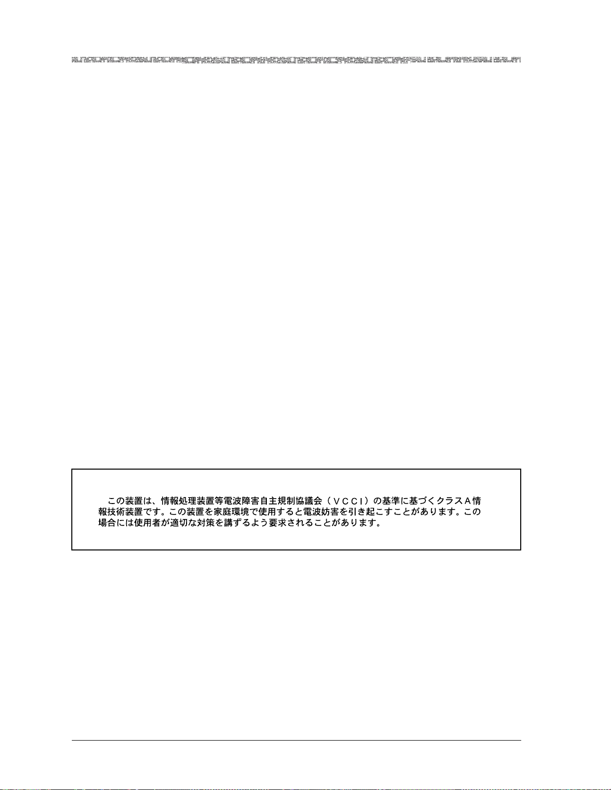
VCCI This is a Class A product based on the standard of the Voluntary Control
Council for Interference by Information Technology Equipment (VCCI). If
this equipment is used in a domestic environment, radio disturbance may
occur, in which case, the user may be required to take corrective actions.
JATE This equipment complies with the Japan Approvals Institute for Telecommu-
nication Equipment (JA TE) requirem ents when used in conjunct ion with the
I/O modules listed in Table 1.
PacketStar® PSAX 1250 Multiservice Media Gateway User Guide, Issue 2 Release 8.0.0
xii 255-700-247
Page 13

Legal Notices, Safety, and Regulatory Information
Regulatory Statements
Table 1. JATE Approved Modules
Module
Model
Number
20N33
20N36
20N62
20N63
20N64
20N65
20N92
20N93
Module Description
6-Port DS1 IMA (
6-Port Enhanced DS1/T1 Multiservice (
1-Port STM-1 Multimode with AQueMan (
1-Port ST M-1 Single-Mode with AQueMan (
IMA DS1)
DS1/T1 Enh)
STM-1 (MM AQ))
STM-1 (SM AQ))
1-Port STM-1 Multimode with Traffic Shaping (
1-Port STM-1 Single-Mode with Traffic Shaping (
1-Port STM-1 1+1 MSP Multimode (
1-Port STM-1 1+1 MSP Single-Mode (
STM-1 MM MSP)
STM-1 SM MSP)
STM-1 (MM TS))
STM-1 (SM TS))
Jate
Approval
Number
D00-0807
D00-0807
L00-0198
L00-0198
L00-0198
L00-0198
L00-0230
L00-0230
CISPR 22, EN 55022, AS/NZS-3548 Class A Electromagnetic Compatibility (EMC)
Regulatory Statement
This is a Class A product. In a domestic environment, this product may cause
radio interference, in which case the user may be required to take adequate
measures.
PacketStar® PSAX 1250 Multiservice Media Gateway User Guide, Issue 2 Release 8.0.0
255-700-247 xiii
Page 14

Legal Notices, Safety, and Regulatory Information
Regulatory Statements
PacketStar® PSAX 1250 Multiservice Media Gateway User Guide, Issue 2 Release 8.0.0
xiv 255-700-247
Page 15

Contents
Legal Notices, Safety, and Regulatory Information . . . . . . . . . . . . . . . . . iii
Copyright . . . . . . . . . . . . . . . . . . . . . . . . . . . . . . . . . . . . . . . . . . . . . . . . . . . . . . . . . . . . . iii
Trademarks . . . . . . . . . . . . . . . . . . . . . . . . . . . . . . . . . . . . . . . . . . . . . . . . . . . . . . . . . . . . iii
Notices . . . . . . . . . . . . . . . . . . . . . . . . . . . . . . . . . . . . . . . . . . . . . . . . . . . . . . . . . . . . . . . iii
Warranty Information . . . . . . . . . . . . . . . . . . . . . . . . . . . . . . . . . . . . . . . . . . . . . . . . . . . . . iii
Software and Hardware Limited Warranties . . . . . . . . . . . . . . . . . . . . . . . . . . . . . . . . . iii
Warranty Warnings . . . . . . . . . . . . . . . . . . . . . . . . . . . . . . . . . . . . . . . . . . . . . . . . . . . iv
Regulatory Standards Compliance . . . . . . . . . . . . . . . . . . . . . . . . . . . . . . . . . . . . . . . . . . . v
Safety . . . . . . . . . . . . . . . . . . . . . . . . . . . . . . . . . . . . . . . . . . . . . . . . . . . . . . . . . . . . . v
Electromagnetic Compatibility . . . . . . . . . . . . . . . . . . . . . . . . . . . . . . . . . . . . . . . . . . . v
Telecommunications . . . . . . . . . . . . . . . . . . . . . . . . . . . . . . . . . . . . . . . . . . . . . . . . . . v
Regulatory Statements . . . . . . . . . . . . . . . . . . . . . . . . . . . . . . . . . . . . . . . . . . . . . . . . . . . . vi
USA Regulatory Statements . . . . . . . . . . . . . . . . . . . . . . . . . . . . . . . . . . . . . . . . . . . . . vi
FCC Part 15 . . . . . . . . . . . . . . . . . . . . . . . . . . . . . . . . . . . . . . . . . . . . . . . . . . . . . vi
FCC Part 68 . . . . . . . . . . . . . . . . . . . . . . . . . . . . . . . . . . . . . . . . . . . . . . . . . . . . . vi
Canadian Regulatory Statements . . . . . . . . . . . . . . . . . . . . . . . . . . . . . . . . . . . . . . . . .vii
ICES-003 . . . . . . . . . . . . . . . . . . . . . . . . . . . . . . . . . . . . . . . . . . . . . . . . . . . . . . . .vii
NMB-003 . . . . . . . . . . . . . . . . . . . . . . . . . . . . . . . . . . . . . . . . . . . . . . . . . . . . . . .vii
CS-03 Issue 8 . . . . . . . . . . . . . . . . . . . . . . . . . . . . . . . . . . . . . . . . . . . . . . . . . . . .vii
SH-03 Version 8 . . . . . . . . . . . . . . . . . . . . . . . . . . . . . . . . . . . . . . . . . . . . . . . . . .vii
European Union Regulatory Statement . . . . . . . . . . . . . . . . . . . . . . . . . . . . . . . . . . . viii
CE Marking . . . . . . . . . . . . . . . . . . . . . . . . . . . . . . . . . . . . . . . . . . . . . . . . . . . . . viii
EN 300 386-2 . . . . . . . . . . . . . . . . . . . . . . . . . . . . . . . . . . . . . . . . . . . . . . . . . . . .xii
Japanese Regulatory Statements . . . . . . . . . . . . . . . . . . . . . . . . . . . . . . . . . . . . . . . . .xii
VCCI . . . . . . . . . . . . . . . . . . . . . . . . . . . . . . . . . . . . . . . . . . . . . . . . . . . . . . . . . . .xii
JATE . . . . . . . . . . . . . . . . . . . . . . . . . . . . . . . . . . . . . . . . . . . . . . . . . . . . . . . . . . .xii
CISPR 22, EN 55022, AS/NZS-3548 Class A Electromagnetic Compatibility (EMC) Regula-
tory Statement . . . . . . . . . . . . . . . . . . . . . . . . . . . . . . . . . . . . . . . . . . . . . . . . . . . . xiii
List of Figures . . . . . . . . . . . . . . . . . . . . . . . . . . . . . . . . . . . . . . . . . . . . . xxvii
List of Tables . . . . . . . . . . . . . . . . . . . . . . . . . . . . . . . . . . . . . . . . . . . . . . xxxi
1 Getting Started. . . . . . . . . . . . . . . . . . . . . . . . . . . . . . . . . . . . . . . . . . . . . . 1-1
Purpose of This Guide . . . . . . . . . . . . . . . . . . . . . . . . . . . . . . . . . . . . . . . . . . . . . . . . . . . .1-1
Audience for This Guide . . . . . . . . . . . . . . . . . . . . . . . . . . . . . . . . . . . . . . . . . . . . . . . . . .1-1
PacketStar® PSAX 1250 Multiservice Media Gateway User Guide, Issue 2 Release 8.0.0
255-700-247 xv
Page 16

Contents
What You Should Know . . . . . . . . . . . . . . . . . . . . . . . . . . . . . . . . . . . . . . . . . . . . . . . . . .1-1
Related Reading . . . . . . . . . . . . . . . . . . . . . . . . . . . . . . . . . . . . . . . . . . . . . . . . . . . . . . . .1-2
Product Information Library . . . . . . . . . . . . . . . . . . . . . . . . . . . . . . . . . . . . . . . . . . . .1-2
Printed Documents. . . . . . . . . . . . . . . . . . . . . . . . . . . . . . . . . . . . . . . . . . . . . . . . . . .1-2
Other Publications . . . . . . . . . . . . . . . . . . . . . . . . . . . . . . . . . . . . . . . . . . . . . . . . . . .1-2
Conventions . . . . . . . . . . . . . . . . . . . . . . . . . . . . . . . . . . . . . . . . . . . . . . . . . . . . . . . . . . .1-2
Text Types Used in This Document. . . . . . . . . . . . . . . . . . . . . . . . . . . . . . . . . . . . . . . .1-2
Icons and Symbols . . . . . . . . . . . . . . . . . . . . . . . . . . . . . . . . . . . . . . . . . . . . . . . . . . .1-3
Command Description Tables . . . . . . . . . . . . . . . . . . . . . . . . . . . . . . . . . . . . . . . . . . .1-3
Field Description Tables. . . . . . . . . . . . . . . . . . . . . . . . . . . . . . . . . . . . . . . . . . . . . . . .1-4
Selecting Options, Fields, and Commands. . . . . . . . . . . . . . . . . . . . . . . . . . . . . . . . . .1-4
Help Information. . . . . . . . . . . . . . . . . . . . . . . . . . . . . . . . . . . . . . . . . . . . . . . . . . . . . . . .1-5
Technical Support . . . . . . . . . . . . . . . . . . . . . . . . . . . . . . . . . . . . . . . . . . . . . . . . . . . . . . .1-7
About Lucent Technologies . . . . . . . . . . . . . . . . . . . . . . . . . . . . . . . . . . . . . . . . . . . . . . . .1-7
History . . . . . . . . . . . . . . . . . . . . . . . . . . . . . . . . . . . . . . . . . . . . . . . . . . . . . . . . . . . .1-7
For More Information . . . . . . . . . . . . . . . . . . . . . . . . . . . . . . . . . . . . . . . . . . . . . . . . .1-7
About the PacketStar PSAX Product Family . . . . . . . . . . . . . . . . . . . . . . . . . . . . . . . . . . . .1-7
PSAX 1000 Multiservice Media Gateway. . . . . . . . . . . . . . . . . . . . . . . . . . . . . . . . . . .1-7
PSAX 1250 Multiservice Media Gateway. . . . . . . . . . . . . . . . . . . . . . . . . . . . . . . . . . .1-8
PSAX 2300 Multiservice Media Gateway. . . . . . . . . . . . . . . . . . . . . . . . . . . . . . . . . . .1-8
PSAX 4500 Multiservice Media Gateway. . . . . . . . . . . . . . . . . . . . . . . . . . . . . . . . . . .1-9
Comments on This Guide . . . . . . . . . . . . . . . . . . . . . . . . . . . . . . . . . . . . . . . . . . . . . . . . .1-9
2 Hardware Description . . . . . . . . . . . . . . . . . . . . . . . . . . . . . . . . . . . . . . . . 2-1
Overview of This Chapter . . . . . . . . . . . . . . . . . . . . . . . . . . . . . . . . . . . . . . . . . . . . . . . . .2-1
System Features . . . . . . . . . . . . . . . . . . . . . . . . . . . . . . . . . . . . . . . . . . . . . . . . . . . . . . . .2-1
System Hardware Components . . . . . . . . . . . . . . . . . . . . . . . . . . . . . . . . . . . . . . . . . . . . .2-1
Functional Description. . . . . . . . . . . . . . . . . . . . . . . . . . . . . . . . . . . . . . . . . . . . . . . . . . . .2-3
Chassis. . . . . . . . . . . . . . . . . . . . . . . . . . . . . . . . . . . . . . . . . . . . . . . . . . . . . . . . . . . .2-3
Module Slot Locations . . . . . . . . . . . . . . . . . . . . . . . . . . . . . . . . . . . . . . . . . . . . . . . .2-3
Backplane. . . . . . . . . . . . . . . . . . . . . . . . . . . . . . . . . . . . . . . . . . . . . . . . . . . . . . . . . .2-4
Power Supply Modules . . . . . . . . . . . . . . . . . . . . . . . . . . . . . . . . . . . . . . . . . . . . . . . .2-5
Stratum 3–4 Module . . . . . . . . . . . . . . . . . . . . . . . . . . . . . . . . . . . . . . . . . . . . . . . . .2-6
CPU2 Module. . . . . . . . . . . . . . . . . . . . . . . . . . . . . . . . . . . . . . . . . . . . . . . . . . . . . . .2-7
Hardware Specifications . . . . . . . . . . . . . . . . . . . . . . . . . . . . . . . . . . . . . . . . . . . . . . . . . .2-7
Chassis Specifications. . . . . . . . . . . . . . . . . . . . . . . . . . . . . . . . . . . . . . . . . . . . . . . . .2-7
System Environmental Specifications. . . . . . . . . . . . . . . . . . . . . . . . . . . . . . . . . . . . . .2-8
Power Supply Module Specifications. . . . . . . . . . . . . . . . . . . . . . . . . . . . . . . . . . . . . .2-8
110 V ac Power Supply . . . . . . . . . . . . . . . . . . . . . . . . . . . . . . . . . . . . . . . . . . . .2-9
PacketStar® PSAX 1250 Multiservice Media Gateway User Guide, Issue 2 Release 8.0.0
255-700-247 xvi
Page 17

Contents
220 V ac Power Supply . . . . . . . . . . . . . . . . . . . . . . . . . . . . . . . . . . . . . . . . . . . .2-9
-48 V dc Power Supply. . . . . . . . . . . . . . . . . . . . . . . . . . . . . . . . . . . . . . . . . . . .2-10
Stratum 3–4 Module Specifications. . . . . . . . . . . . . . . . . . . . . . . . . . . . . . . . . . . . . .2-10
CPU2 Module Specifications. . . . . . . . . . . . . . . . . . . . . . . . . . . . . . . . . . . . . . . . . . .2-11
PacketStar I/O and Server Module Hardware Specifications . . . . . . . . . . . . . . . . . . . .2-11
Module Performance and Power Specifications. . . . . . . . . . . . . . . . . . . . . . . . . . . . .2-11
3 System Features. . . . . . . . . . . . . . . . . . . . . . . . . . . . . . . . . . . . . . . . . . . . . 3-1
Overview of This Chapter . . . . . . . . . . . . . . . . . . . . . . . . . . . . . . . . . . . . . . . . . . . . . . . . .3-1
System Capabilities . . . . . . . . . . . . . . . . . . . . . . . . . . . . . . . . . . . . . . . . . . . . . . . . . . . . . .3-1
PSAX System User Benefits . . . . . . . . . . . . . . . . . . . . . . . . . . . . . . . . . . . . . . . . . . . . .3-1
PSAX System Feature Highlights . . . . . . . . . . . . . . . . . . . . . . . . . . . . . . . . . . . . . . . . .3-1
Interface Architecture . . . . . . . . . . . . . . . . . . . . . . . . . . . . . . . . . . . . . . . . . . . . . . . . . . . .3-2
Connections Support . . . . . . . . . . . . . . . . . . . . . . . . . . . . . . . . . . . . . . . . . . . . . . . . . . . .3-3
Soft Permanent Virtual Circuit (SPVC) Connections . . . . . . . . . . . . . . . . . . . . . . . . . . .3-3
SPVC Reconnection Prioritization . . . . . . . . . . . . . . . . . . . . . . . . . . . . . . . . . . . . . . . .3-4
Switched Virtual Circuit (SVC) Connections. . . . . . . . . . . . . . . . . . . . . . . . . . . . . . . . .3-6
SVC Functional Description . . . . . . . . . . . . . . . . . . . . . . . . . . . . . . . . . . . . . . . . .3-7
Call States . . . . . . . . . . . . . . . . . . . . . . . . . . . . . . . . . . . . . . . . . . . . . . . . . . . . . .3-7
User Interfaces . . . . . . . . . . . . . . . . . . . . . . . . . . . . . . . . . . . . . . . . . . . . . . . . . . . . . . . .3-10
Circuit Emulation Service . . . . . . . . . . . . . . . . . . . . . . . . . . . . . . . . . . . . . . . . . . . . .3-10
SPVC Support for CES . . . . . . . . . . . . . . . . . . . . . . . . . . . . . . . . . . . . . . . . . . . .3-10
Circuit Emulation Service for the Multiserial Module. . . . . . . . . . . . . . . . . . . . . .3-10
Dynamic Bandwidth Circuit Emulation Service. . . . . . . . . . . . . . . . . . . . . . . . . . . . . .3-11
Dynamic CAC. . . . . . . . . . . . . . . . . . . . . . . . . . . . . . . . . . . . . . . . . . . . . . . . . . . . . .3-11
DS1 Service . . . . . . . . . . . . . . . . . . . . . . . . . . . . . . . . . . . . . . . . . . . . . . . . . . . . . . .3-11
DS3 Service . . . . . . . . . . . . . . . . . . . . . . . . . . . . . . . . . . . . . . . . . . . . . . . . . . . . . . .3-12
HDLC Passthrough Bit Inversion . . . . . . . . . . . . . . . . . . . . . . . . . . . . . . . . . . . . . . . .3-12
Interim Interswitch Signaling Protocol (IISP) Interface. . . . . . . . . . . . . . . . . . . . . . . . .3-12
Private Network-Network Interface (PNNI) 1.0. . . . . . . . . . . . . . . . . . . . . . . . . . . . . .3-12
Overview . . . . . . . . . . . . . . . . . . . . . . . . . . . . . . . . . . . . . . . . . . . . . . . . . . . . . .3-12
PNNI Features Supported by the PSAX Systems. . . . . . . . . . . . . . . . . . . . . . . . . .3-13
PNNI Peer Group Dynamics . . . . . . . . . . . . . . . . . . . . . . . . . . . . . . . . . . . . . . . .3-13
PNNI Topology State Element (PTSE) Information . . . . . . . . . . . . . . . . . . . . . . . .3-14
PNNI Hierarchies. . . . . . . . . . . . . . . . . . . . . . . . . . . . . . . . . . . . . . . . . . . . . . . . .3-14
ATM Maintenance . . . . . . . . . . . . . . . . . . . . . . . . . . . . . . . . . . . . . . . . . . . . . . .3-16
Integrated Link Management Interface (ILMI) . . . . . . . . . . . . . . . . . . . . . . . . . . . . . .3-17
ILMI over PNNI Overview . . . . . . . . . . . . . . . . . . . . . . . . . . . . . . . . . . . . . . . . . .3-17
Load Balancing for IISP and PNNI . . . . . . . . . . . . . . . . . . . . . . . . . . . . . . . . . . . .3-18
PacketStar® PSAX 1250 Multiservice Media Gateway User Guide, Issue 2 Release 8.0.0
255-700-247 xvii
Page 18

Contents
ATM Terminal Emulation. . . . . . . . . . . . . . . . . . . . . . . . . . . . . . . . . . . . . . . . . . . . . .3-18
UNI 4.0 Signaling . . . . . . . . . . . . . . . . . . . . . . . . . . . . . . . . . . . . . . . . . . . . . . . . . . .3-18
Inverse Multiplexing for ATM (IMA). . . . . . . . . . . . . . . . . . . . . . . . . . . . . . . . . . . . . .3-18
Automatic Use of IMA Links . . . . . . . . . . . . . . . . . . . . . . . . . . . . . . . . . . . . . . . . . . .3-19
IMA Configuration Considerations . . . . . . . . . . . . . . . . . . . . . . . . . . . . . . . . . . . . . .3-19
Frame Relay-to-ATM Interworking . . . . . . . . . . . . . . . . . . . . . . . . . . . . . . . . . . . . . .3-20
FRF.5 Encapsulating Frames . . . . . . . . . . . . . . . . . . . . . . . . . . . . . . . . . . . . . . . .3-20
FRF.8 Converting Frames . . . . . . . . . . . . . . . . . . . . . . . . . . . . . . . . . . . . . . . . . .3-20
Frame Relay-to-Frame Relay Interworking . . . . . . . . . . . . . . . . . . . . . . . . . . . . . . . . .3-20
GR-303 Interface . . . . . . . . . . . . . . . . . . . . . . . . . . . . . . . . . . . . . . . . . . . . . . . . . . .3-20
Network Management . . . . . . . . . . . . . . . . . . . . . . . . . . . . . . . . . . . . . . . . . . . . . . . . . .3-23
AQueView
®
Element Management System. . . . . . . . . . . . . . . . . . . . . . . . . . . . . . . .3-24
Multiservice Media Gateway Software Features. . . . . . . . . . . . . . . . . . . . . . . . . . . . . . . .3-25
Connection Gateway API . . . . . . . . . . . . . . . . . . . . . . . . . . . . . . . . . . . . . . . . . . . . .3-25
Connection Gateway API Overview . . . . . . . . . . . . . . . . . . . . . . . . . . . . . . . . . .3-25
The PSAX 1250 As a TCP Client/Server for the Connection Gateway API . . . . . .3-26
DS1 ANI In-line Codes for Loopbacks . . . . . . . . . . . . . . . . . . . . . . . . . . . . . . . . . . . .3-27
DS0A Non-Latched Loop Codes . . . . . . . . . . . . . . . . . . . . . . . . . . . . . . . . . . . . . . . .3-27
PSAX 1250 System Traffic Protection Capabilities . . . . . . . . . . . . . . . . . . . . . . . . . . .3-28
APS/MSP Protection on the Optical Modules . . . . . . . . . . . . . . . . . . . . . . . . . . .3-28
Interface Protection Group Feature. . . . . . . . . . . . . . . . . . . . . . . . . . . . . . . . . . .3-29
Alternate Rerouting Using Dual-Homed PVCs. . . . . . . . . . . . . . . . . . . . . . . . . . .3-30
Firmware Release Control . . . . . . . . . . . . . . . . . . . . . . . . . . . . . . . . . . . . . . . . . . . . .3-32
H.248 Media Gateway Access Protocol. . . . . . . . . . . . . . . . . . . . . . . . . . . . . . . . . . .3-33
Forward Error Correction . . . . . . . . . . . . . . . . . . . . . . . . . . . . . . . . . . . . . . . . . . . . .3-33
Internet Protocol (IP) Throttling . . . . . . . . . . . . . . . . . . . . . . . . . . . . . . . . . . . . . . . . .3-35
LANET Protocol. . . . . . . . . . . . . . . . . . . . . . . . . . . . . . . . . . . . . . . . . . . . . . . . . . . . .3-35
Operations, Administration, and Maintenance (OAM). . . . . . . . . . . . . . . . . . . . . . . .3-38
Overview of OAM . . . . . . . . . . . . . . . . . . . . . . . . . . . . . . . . . . . . . . . . . . . . . . .3-38
OAM Cell Characteristics . . . . . . . . . . . . . . . . . . . . . . . . . . . . . . . . . . . . . . . . . .3-38
OAM ATM Layer Flows. . . . . . . . . . . . . . . . . . . . . . . . . . . . . . . . . . . . . . . . . . . .3-39
OAM F4 Flows . . . . . . . . . . . . . . . . . . . . . . . . . . . . . . . . . . . . . . . . . . . . . . . . . .3-40
OAM F5 Flows . . . . . . . . . . . . . . . . . . . . . . . . . . . . . . . . . . . . . . . . . . . . . . . . . .3-40
ATM Layer OAM Functions. . . . . . . . . . . . . . . . . . . . . . . . . . . . . . . . . . . . . . . . .3-41
Packet Pipe AAL5-to-AAL2 Wireless Trunking for Mobile Voice. . . . . . . . . . . . . . . . .3-42
Reduction in Post-Dial Delay . . . . . . . . . . . . . . . . . . . . . . . . . . . . . . . . . . . . . . . . . . .3-43
Trap Descriptions . . . . . . . . . . . . . . . . . . . . . . . . . . . . . . . . . . . . . . . . . . . . . . . . . . .3-43
Traffic Management Using the AQueMan Algorithm. . . . . . . . . . . . . . . . . . . . . . . . .3-43
ATM Traffic Management (UPC Support) . . . . . . . . . . . . . . . . . . . . . . . . . . . . . . . . .3-47
PacketStar® PSAX 1250 Multiservice Media Gateway User Guide, Issue 2 Release 8.0.0
255-700-247 xviii
Page 19

Contents
Cell Bus Traffic Shaping . . . . . . . . . . . . . . . . . . . . . . . . . . . . . . . . . . . . . . . . . . . . . .3-47
ATM Traffic Shaping . . . . . . . . . . . . . . . . . . . . . . . . . . . . . . . . . . . . . . . . . . . . . . . . .3-50
Overview of ATM Traffic Shaping . . . . . . . . . . . . . . . . . . . . . . . . . . . . . . . . . . . .3-50
Configuring ATM Traffic Shaping for HDLC, Frame Relay, and Ethernet Virtual
Channels . . . . . . . . . . . . . . . . . . . . . . . . . . . . . . . . . . . . . . . . . . . . . . . . . . . .3-50
Task Summary for Implementing ATM Traffic Shaping. . . . . . . . . . . . . . . . . . . . .3-51
VBR ATM Traffic Shaping Priorities . . . . . . . . . . . . . . . . . . . . . . . . . . . . . . . . . . .3-51
ATM Traffic Shaping for CBR and VBR-rt. . . . . . . . . . . . . . . . . . . . . . . . . . . . . . .3-51
Maximum Number of ATM Traffic-Shaped Connections . . . . . . . . . . . . . . . . . . .3-52
How the ATM Traffic Shaping Algorithm Works . . . . . . . . . . . . . . . . . . . . . . . . .3-52
Formula for Determining the PCR of an ATM Traffic-Shaped Connection . . . . . .3-53
V5.2 European IDLC . . . . . . . . . . . . . . . . . . . . . . . . . . . . . . . . . . . . . . . . . . . . . . . . .3-54
Virtual Interfaces . . . . . . . . . . . . . . . . . . . . . . . . . . . . . . . . . . . . . . . . . . . . . . . . . . .3-54
Voice Compression. . . . . . . . . . . . . . . . . . . . . . . . . . . . . . . . . . . . . . . . . . . . . . . . . .3-54
Voice Processing. . . . . . . . . . . . . . . . . . . . . . . . . . . . . . . . . . . . . . . . . . . . . . . . . . . .3-55
Echo Cancellation. . . . . . . . . . . . . . . . . . . . . . . . . . . . . . . . . . . . . . . . . . . . . . . . . . .3-55
Wireless Mobile Voice Backhaul . . . . . . . . . . . . . . . . . . . . . . . . . . . . . . . . . . . . . . . .3-55
Virtual Routing . . . . . . . . . . . . . . . . . . . . . . . . . . . . . . . . . . . . . . . . . . . . . . . . . . . . .3-56
PSAX Module Features . . . . . . . . . . . . . . . . . . . . . . . . . . . . . . . . . . . . . . . . . . . . . . . . . .3-58
4 Site-Specific Configuration . . . . . . . . . . . . . . . . . . . . . . . . . . . . . . . . . . . . 4-1
Overview of This Chapter . . . . . . . . . . . . . . . . . . . . . . . . . . . . . . . . . . . . . . . . . . . . . . . . .4-1
Logging onto the System . . . . . . . . . . . . . . . . . . . . . . . . . . . . . . . . . . . . . . . . . . . . . . . . .4-1
Changing the System Password and Other User Options . . . . . . . . . . . . . . . . . . . . . . . . . .4-4
Console Interface Main Menu Options . . . . . . . . . . . . . . . . . . . . . . . . . . . . . . . . . . . . . . .4-8
Site-Specific Configuration Menu Options. . . . . . . . . . . . . . . . . . . . . . . . . . . . . . . . . . . . .4-8
Configuring the System for Your Site . . . . . . . . . . . . . . . . . . . . . . . . . . . . . . . . . . . . . . . .4-9
Accessing the Site-Specific Menu . . . . . . . . . . . . . . . . . . . . . . . . . . . . . . . . . . . . . . .4-10
Configuring System Identification Information . . . . . . . . . . . . . . . . . . . . . . . . . . . . .4-13
Rules for Configuring IP Addresses . . . . . . . . . . . . . . . . . . . . . . . . . . . . . . . . . . . . . .4-15
Rules for Configuring IP Address Masks . . . . . . . . . . . . . . . . . . . . . . . . . . . . . . . . . .4-16
Configuring System Identification. . . . . . . . . . . . . . . . . . . . . . . . . . . . . . . . . . . . . . .4-16
ATM Addresses and OAM Properties . . . . . . . . . . . . . . . . . . . . . . . . . . . . . . . . .4-16
Configuring System Date and Time. . . . . . . . . . . . . . . . . . . . . . . . . . . . . . . . . . . . . .4-19
Configuring the PSAX System as a TCP Server or a TCP Client . . . . . . . . . . . . . . . . .4-20
Configuring SNMP Trap Destinations . . . . . . . . . . . . . . . . . . . . . . . . . . . . . . . . . . . .4-23
Configuring Call Control Resource Allocation . . . . . . . . . . . . . . . . . . . . . . . . . . . . . . . . .4-25
Setting the Configuration Values . . . . . . . . . . . . . . . . . . . . . . . . . . . . . . . . . . . . . . .4-25
Saving the Configuration and Rebooting the System . . . . . . . . . . . . . . . . . . . . . . . .4-30
PacketStar® PSAX 1250 Multiservice Media Gateway User Guide, Issue 2 Release 8.0.0
255-700-247 xix
Page 20

Contents
Backing Up Configuration Data . . . . . . . . . . . . . . . . . . . . . . . . . . . . . . . . . . . . . . . .4-32
Configuring GR-303 . . . . . . . . . . . . . . . . . . . . . . . . . . . . . . . . . . . . . . . . . . . . . . . . . . . .4-32
Configuring TAS Module System-Wide Use. . . . . . . . . . . . . . . . . . . . . . . . . . . . . . . . . . .4-32
Configuring H.248 (Media Gateway Control Protocol). . . . . . . . . . . . . . . . . . . . . . . . . . .4-32
Configuring DSP Resource Use . . . . . . . . . . . . . . . . . . . . . . . . . . . . . . . . . . . . . . . . . . . .4-33
Enabling and Disabling System-Wide Features. . . . . . . . . . . . . . . . . . . . . . . . . . . . . . . . .4-33
Rebooting Redundant or Non-Redundant PSAX System CPUs . . . . . . . . . . . . . . . . . . . . .4-36
Configuring Interface Protection Groups . . . . . . . . . . . . . . . . . . . . . . . . . . . . . . . . . . . . .4-40
Setting Up an Interface Protection Group ID . . . . . . . . . . . . . . . . . . . . . . . . . . . . . . .4-40
Creating an Interface Protection Group. . . . . . . . . . . . . . . . . . . . . . . . . . . . . . . . . . .4-45
Internet Protocol (IP) Throttling . . . . . . . . . . . . . . . . . . . . . . . . . . . . . . . . . . . . . . . . . . . .4-48
SNMP Trap Activation/Deactivation . . . . . . . . . . . . . . . . . . . . . . . . . . . . . . . . . . . . . . . . .4-53
Enabling and Disabling SNMP Trap Messages . . . . . . . . . . . . . . . . . . . . . . . . . . . . . .4-54
Trap Activation Table Window . . . . . . . . . . . . . . . . . . . . . . . . . . . . . . . . . . . . . . . . .4-54
Using the Equipment Configuration Window . . . . . . . . . . . . . . . . . . . . . . . . . . . . . . . . .4-56
Configuring the Stratu m 3–4 Module . . . . . . . . . . . . . . . . . . . . . . . . . . . . . . . . . . . . . . .4-61
Setting the Stratum Configuration Values. . . . . . . . . . . . . . . . . . . . . . . . . . . . . . . . .4-61
Switching the Line Timing Source . . . . . . . . . . . . . . . . . . . . . . . . . . . . . . . . . . . . . . .4-68
Alarm Status Values . . . . . . . . . . . . . . . . . . . . . . . . . . . . . . . . . . . . . . . . . . . . . . . . .4-68
Saving the Equipment Configuration Values and Logging Off . . . . . . . . . . . . . . . . . . . . .4-69
5 Configuring PNNI . . . . . . . . . . . . . . . . . . . . . . . . . . . . . . . . . . . . . . . . . . . . 5-1
PNNI System-Wide Configuration . . . . . . . . . . . . . . . . . . . . . . . . . . . . . . . . . . . . . . . . . . .5-1
Configuring the PNNI Node . . . . . . . . . . . . . . . . . . . . . . . . . . . . . . . . . . . . . . . . . . . .5-1
Modifying PNNI Configurations . . . . . . . . . . . . . . . . . . . . . . . . . . . . . . . . . . . . . . . . .5-9
Configuring the PNNI Node Peer Group Leader (PGL) . . . . . . . . . . . . . . . . . . . . . . . . .5-9
Configuring the PNNI Node Timer. . . . . . . . . . . . . . . . . . . . . . . . . . . . . . . . . . . . . . .5-13
Configuring the PNNI Node SVCC . . . . . . . . . . . . . . . . . . . . . . . . . . . . . . . . . . . . . .5-16
Configuring the PNNI Node Scope Mapping . . . . . . . . . . . . . . . . . . . . . . . . . . . . . . .5-18
Configuring the PNNI Route Addresses. . . . . . . . . . . . . . . . . . . . . . . . . . . . . . . . . . .5-20
Configuring PNNI Metrics. . . . . . . . . . . . . . . . . . . . . . . . . . . . . . . . . . . . . . . . . . . . .5-25
Configuring PNNI Route TNS . . . . . . . . . . . . . . . . . . . . . . . . . . . . . . . . . . . . . . . . . .5-30
Viewing PNNI Map TNS Information . . . . . . . . . . . . . . . . . . . . . . . . . . . . . . . . . . . . .5-35
Configuring Summary Addresses . . . . . . . . . . . . . . . . . . . . . . . . . . . . . . . . . . . . . . .5-39
Viewing the PNNI Map Information . . . . . . . . . . . . . . . . . . . . . . . . . . . . . . . . . . . . .5-42
Viewing PNNI Map Node Information . . . . . . . . . . . . . . . . . . . . . . . . . . . . . . . . . . . .5-46
Viewing PNNI Map Address Information . . . . . . . . . . . . . . . . . . . . . . . . . . . . . . . . . .5-51
Viewing the PNNI Link Table . . . . . . . . . . . . . . . . . . . . . . . . . . . . . . . . . . . . . . . . . . .5-54
Viewing the PNNI SVCC RCC Information. . . . . . . . . . . . . . . . . . . . . . . . . . . . . . . . .5-60
PacketStar® PSAX 1250 Multiservice Media Gateway User Guide, Issue 2 Release 8.0.0
255-700-247 xx
Page 21

Contents
Viewing the PNNI Neighbor Peer Table . . . . . . . . . . . . . . . . . . . . . . . . . . . . . . . . . . .5-64
Viewing the PNNI Neighbor Peer Port Table. . . . . . . . . . . . . . . . . . . . . . . . . . . . . . . .5-68
Viewing PNNI Topology State Element (PTSE) Information . . . . . . . . . . . . . . . . . . . . .5-70
Viewing PNNI System Statistics . . . . . . . . . . . . . . . . . . . . . . . . . . . . . . . . . . . . . . . . .5-74
6 Using VT100 Terminal Emulation . . . . . . . . . . . . . . . . . . . . . . . . . . . . . . . 6-1
Overview of This Chapter . . . . . . . . . . . . . . . . . . . . . . . . . . . . . . . . . . . . . . . . . . . . . . . . .6-1
Setting Up The Windows HyperTerminal Emulator. . . . . . . . . . . . . . . . . . . . . . . . . . . . . . .6-1
Connecting a Dialup Modem to the Chassis . . . . . . . . . . . . . . . . . . . . . . . . . . . . . . . . . . .6-3
7 Configuring ATM Trunking . . . . . . . . . . . . . . . . . . . . . . . . . . . . . . . . . . . . 7-1
Overview of This Chapter . . . . . . . . . . . . . . . . . . . . . . . . . . . . . . . . . . . . . . . . . . . . . . . . .7-1
Configuring the Local IWF Node. . . . . . . . . . . . . . . . . . . . . . . . . . . . . . . . . . . . . . . . .7-1
Configuring a Remote IWF Node . . . . . . . . . . . . . . . . . . . . . . . . . . . . . . . . . . . . . . . .7-4
Adding a Signaling VCC Identifier. . . . . . . . . . . . . . . . . . . . . . . . . . . . . . . . . . . . . . . .7-9
Adding a Bearer VCC Identifier. . . . . . . . . . . . . . . . . . . . . . . . . . . . . . . . . . . . . . . . .7-14
Adding a Narrowband Address. . . . . . . . . . . . . . . . . . . . . . . . . . . . . . . . . . . . . . . . .7-23
Adding a Broadband Address . . . . . . . . . . . . . . . . . . . . . . . . . . . . . . . . . . . . . . . . . .7-25
Viewing ATM Trunking Information . . . . . . . . . . . . . . . . . . . . . . . . . . . . . . . . . . . . .7-27
8 Configuring V5.2 European IDLC . . . . . . . . . . . . . . . . . . . . . . . . . . . . . . . 8-1
Overview of the V5.2 European IDLC . . . . . . . . . . . . . . . . . . . . . . . . . . . . . . . . . . . . . . . .8-1
V5.2 PSTN Implementation on the PSAX System . . . . . . . . . . . . . . . . . . . . . . . . . . . . . . . .8-1
V5.2 ISDN Implementation on the PSAX System . . . . . . . . . . . . . . . . . . . . . . . . . . . . . . . .8-4
PSTN Configuration . . . . . . . . . . . . . . . . . . . . . . . . . . . . . . . . . . . . . . . . . . . . . . . . . . . . .8-4
Setting Call Control Resource Allocation Values. . . . . . . . . . . . . . . . . . . . . . . . . . . . . . . . .8-8
9 Using System Diagnostics . . . . . . . . . . . . . . . . . . . . . . . . . . . . . . . . . . . . . 9-1
Overview of This Chapter . . . . . . . . . . . . . . . . . . . . . . . . . . . . . . . . . . . . . . . . . . . . . . . . .9-1
Viewing System Status . . . . . . . . . . . . . . . . . . . . . . . . . . . . . . . . . . . . . . . . . . . . . . . . . . .9-2
Running Cell Test Diagnostics . . . . . . . . . . . . . . . . . . . . . . . . . . . . . . . . . . . . . . . . . . . . . .9-6
Rebooting PSAX Hardware Components. . . . . . . . . . . . . . . . . . . . . . . . . . . . . . . . . . . . .9-11
Removing Configuration Files . . . . . . . . . . . . . . . . . . . . . . . . . . . . . . . . . . . . . . . . . . . . .9-14
Unlocking a T elnet Session . . . . . . . . . . . . . . . . . . . . . . . . . . . . . . . . . . . . . . . . . . . . . . .9-15
Operations Administration and Maintenance (OAM) . . . . . . . . . . . . . . . . . . . . . . . . . . . .9-16
Enabling OAM Loopback Functions. . . . . . . . . . . . . . . . . . . . . . . . . . . . . . . . . . . . . . . . .9-17
OAM Activation and Deactivation. . . . . . . . . . . . . . . . . . . . . . . . . . . . . . . . . . . . . . .9-21
10 Backing Up and Restoring PSAX System Files . . . . . . . . . . . . . . . . . . . . 10-1
Overview of This Chapter . . . . . . . . . . . . . . . . . . . . . . . . . . . . . . . . . . . . . . . . . . . . . . . .10-1
Database Configuration Save and Restore Feature. . . . . . . . . . . . . . . . . . . . . . . . . . . . . .10-1
PacketStar® PSAX 1250 Multiservice Media Gateway User Guide, Issue 2 Release 8.0.0
255-700-247 xxi
Page 22

Contents
Backing Up System Database Files. . . . . . . . . . . . . . . . . . . . . . . . . . . . . . . . . . . . . . . . . .10-2
Remote Database Operation. . . . . . . . . . . . . . . . . . . . . . . . . . . . . . . . . . . . . . . . . . .10-2
Backing Up Database Files Using FTP. . . . . . . . . . . . . . . . . . . . . . . . . . . . . . . . . . . . .10-5
Backing Up Database Files Using XModem/YModem Transfer. . . . . . . . . . . . . . . . . .10-6
Setting Up for the File Transfer Process. . . . . . . . . . . . . . . . . . . . . . . . . . . . . . . .10-7
Copying the Database Files to a Storage Medium. . . . . . . . . . . . . . . . . . . . . . . .10-7
Restoring System Database Files . . . . . . . . . . . . . . . . . . . . . . . . . . . . . . . . . . . . . . . . . .10-13
Configuration and Connection Data Files . . . . . . . . . . . . . . . . . . . . . . . . . . . . .10-13
Restoring Database Files Using FTP . . . . . . . . . . . . . . . . . . . . . . . . . . . . . . . . . . . . .10-14
Restoring Database Files Using FTP. . . . . . . . . . . . . . . . . . . . . . . . . . . . . . . . . .10-14
Rebooting the PSAX System. . . . . . . . . . . . . . . . . . . . . . . . . . . . . . . . . . . . . . .10-15
Restoring Database Files Using XModem/YModem File Transfer . . . . . . . . . . . . . . .10-16
Setting Up for the File Transfer Process. . . . . . . . . . . . . . . . . . . . . . . . . . . . . . .10-16
Copying the Backup Files to the System . . . . . . . . . . . . . . . . . . . . . . . . . . . . . .10-17
Rebooting the PSAX System. . . . . . . . . . . . . . . . . . . . . . . . . . . . . . . . . . . . . . .10-23
Restoring Backup Files to the Standby CPU Module. . . . . . . . . . . . . . . . . . . . .10-23
11 Upgrading PSAX System Software. . . . . . . . . . . . . . . . . . . . . . . . . . . . . 11-1
Overview of This Chapter . . . . . . . . . . . . . . . . . . . . . . . . . . . . . . . . . . . . . . . . . . . . . . . .11-1
Directory Structures. . . . . . . . . . . . . . . . . . . . . . . . . . . . . . . . . . . . . . . . . . . . . . . . . . . . .11-1
Saving Your Modified System Configuration . . . . . . . . . . . . . . . . . . . . . . . . . . . . . . . . . .11-2
Preparing to Install a New Software Release . . . . . . . . . . . . . . . . . . . . . . . . . . . . . . . . . .11-3
Upgrading Using the File Transfer Protocol Method . . . . . . . . . . . . . . . . . . . . . . . . . . . . .11-5
Setting Up a Windows FTP Server . . . . . . . . . . . . . . . . . . . . . . . . . . . . . . . . . . . . . . .11-5
Upgrading the PSAX System Software Using FTP. . . . . . . . . . . . . . . . . . . . . . . . . . . .11-6
Upgrading Using the XModem/YModem File Transfer Method . . . . . . . . . . . . . . . . . . .11-16
Setting Up for the File Transfer Process . . . . . . . . . . . . . . . . . . . . . . . . . . . . . . . . . .11-16
Downloading Software Files Using XModem/YModem . . . . . . . . . . . . . . . . . . . . . .11-17
Upgrading the PSAX System Software Using XModem/YModem Transfer . . . . . . . .11-22
Upgrading Firmware . . . . . . . . . . . . . . . . . . . . . . . . . . . . . . . . . . . . . . . . . . . . . . . . . . .11-23
System Updating of Firmware Drivers . . . . . . . . . . . . . . . . . . . . . . . . . . . . . . . . . . .11-24
Selecting Firmware Drivers . . . . . . . . . . . . . . . . . . . . . . . . . . . . . . . . . . . . . . . . . . .11-24
Upgrading I/O and Server Module Firmware . . . . . . . . . . . . . . . . . . . . . . . . . . . . . .11-25
Falling Back to the Previous Software Release . . . . . . . . . . . . . . . . . . . . . . . . . . . . . . . .11-28
Appendix A SNMP Trap Messages. . . . . . . . . . . . . . . . . . . . . . . . . . . . . . . . . A-1
Overview of This Appendix . . . . . . . . . . . . . . . . . . . . . . . . . . . . . . . . . . . . . . . . . . . . . . . A-1
Viewing Trap Log Information . . . . . . . . . . . . . . . . . . . . . . . . . . . . . . . . . . . . . . . . . . . . . A-1
Definitions of MIB Objects Used for Trap Messages . . . . . . . . . . . . . . . . . . . . . . . . . . . . A-53
PacketStar® PSAX 1250 Multiservice Media Gateway User Guide, Issue 2 Release 8.0.0
255-700-247 xxii
Page 23

Contents
Appendix B Pin Configurations. . . . . . . . . . . . . . . . . . . . . . . . . . . . . . . . . . . B-1
Overview of This Appendix . . . . . . . . . . . . . . . . . . . . . . . . . . . . . . . . . . . . . . . . . . . . . . . .B-1
CONSOLE Connector . . . . . . . . . . . . . . . . . . . . . . . . . . . . . . . . . . . . . . . . . . . . . . . . . . . .B-1
. . . . . . . . . . . . . . . . . . . . . . . . . . . . . . . . . . . . . . . . . . . . . . . . . . . . . . . . . . . . . . . . . . . . .B-2
Configuration for the Stratum 3–4 Connector. . . . . . . . . . . . . . . . . . . . . . . . . . . . . . . . . .B-2
Appendix C Configuring In-Band Management. . . . . . . . . . . . . . . . . . . . . . C-1
Overview of In-band Management Configurations . . . . . . . . . . . . . . . . . . . . . . . . . . . . . C-1
Using the Direct Connection Configuration. . . . . . . . . . . . . . . . . . . . . . . . . . . . . . . . . . . C-2
Setting Up the FORE Card on the SUN Workstation . . . . . . . . . . . . . . . . . . . . . . . . . C-2
Setting Up ATM ARP Table Entries. . . . . . . . . . . . . . . . . . . . . . . . . . . . . . . . . . . . . . . C-3
Using the Routed Connection Configuration. . . . . . . . . . . . . . . . . . . . . . . . . . . . . . . . . . C-4
Setting Up Connections for a Routed Connection Configuration . . . . . . . . . . . . . . . C-5
Setting PVC Connections for Routed Connection Configuration . . . . . . . . . . . . . . . . C-7
Using the Hybrid Connection Configuration . . . . . . . . . . . . . . . . . . . . . . . . . . . . . . . . . C-10
Setting Up Connections for Hybrid Connection Configuration . . . . . . . . . . . . . . . . C-11
Appendix D Reference Information. . . . . . . . . . . . . . . . . . . . . . . . . . . . . . . . D-1
Overview of This Appendix . . . . . . . . . . . . . . . . . . . . . . . . . . . . . . . . . . . . . . . . . . . . . . . D-1
ATM Traffic Descriptors . . . . . . . . . . . . . . . . . . . . . . . . . . . . . . . . . . . . . . . . . . . . . . . . . . D-1
Purpose of Traffic Descriptors . . . . . . . . . . . . . . . . . . . . . . . . . . . . . . . . . . . . . . . . . . D-1
Connections Supporting Traffic Descriptors. . . . . . . . . . . . . . . . . . . . . . . . . . . . . . . . D-1
AT M UNI Specification Cause Codes, Version 3.1 . . . . . . . . . . . . . . . . . . . . . . . . . . . . . . D-3
Industry Compliance Specifications . . . . . . . . . . . . . . . . . . . . . . . . . . . . . . . . . . . . . . . . . D-7
Interface Type by Connection Type Table . . . . . . . . . . . . . . . . . . . . . . . . . . . . . . . . . . . . D-27
Interface Type by Input/Output Module Type Table. . . . . . . . . . . . . . . . . . . . . . . . . . . . . D-28
Module Alarm Status Table . . . . . . . . . . . . . . . . . . . . . . . . . . . . . . . . . . . . . . . . . . . . . . D-33
Quality of Service (QOS) Class Tables . . . . . . . . . . . . . . . . . . . . . . . . . . . . . . . . . . . . . . . D-34
Appendix E PSAX Modules . . . . . . . . . . . . . . . . . . . . . . . . . . . . . . . . . . . . . . E-1
Overview of This Appendix . . . . . . . . . . . . . . . . . . . . . . . . . . . . . . . . . . . . . . . . . . . . . . . .E-1
I/O, Optical, and Server Modules. . . . . . . . . . . . . . . . . . . . . . . . . . . . . . . . . . . . . . . . . . . .E-1
Alarm Module. . . . . . . . . . . . . . . . . . . . . . . . . . . . . . . . . . . . . . . . . . . . . . . . . . . . . . . . . .E-3
Software Features. . . . . . . . . . . . . . . . . . . . . . . . . . . . . . . . . . . . . . . . . . . . . . . . . . . .E-3
Hardware Features . . . . . . . . . . . . . . . . . . . . . . . . . . . . . . . . . . . . . . . . . . . . . . . . . . .E-4
1-Port Channelized DS3 Module . . . . . . . . . . . . . . . . . . . . . . . . . . . . . . . . . . . . . . . . . . . .E-4
Software Features. . . . . . . . . . . . . . . . . . . . . . . . . . . . . . . . . . . . . . . . . . . . . . . . . . . .E-4
Hardware Features . . . . . . . . . . . . . . . . . . . . . . . . . . . . . . . . . . . . . . . . . . . . . . . . . . .E-5
3-Port Channelized DS3/STS-1e CES Module. . . . . . . . . . . . . . . . . . . . . . . . . . . . . . . . . . .E-5
Hardware Features . . . . . . . . . . . . . . . . . . . . . . . . . . . . . . . . . . . . . . . . . . . . . . . . . . .E-6
PacketStar® PSAX 1250 Multiservice Media Gateway User Guide, Issue 2 Release 8.0.0
255-700-247 xxiii
Page 24

Contents
1-Port Channelized STS-1e T1 Module . . . . . . . . . . . . . . . . . . . . . . . . . . . . . . . . . . . . . . .E-7
Software Features. . . . . . . . . . . . . . . . . . . . . . . . . . . . . . . . . . . . . . . . . . . . . . . . . . . .E-7
Hardware Features . . . . . . . . . . . . . . . . . . . . . . . . . . . . . . . . . . . . . . . . . . . . . . . . . . .E-8
6-Port DS1 IMA Module . . . . . . . . . . . . . . . . . . . . . . . . . . . . . . . . . . . . . . . . . . . . . . . . . .E-8
Software Features. . . . . . . . . . . . . . . . . . . . . . . . . . . . . . . . . . . . . . . . . . . . . . . . . . . .E-8
Hardware Features . . . . . . . . . . . . . . . . . . . . . . . . . . . . . . . . . . . . . . . . . . . . . . . . . . .E-8
3-Port Channelized DS3/STS-1e CES Protection Module . . . . . . . . . . . . . . . . . . . . . . . . . .E-9
Software Features. . . . . . . . . . . . . . . . . . . . . . . . . . . . . . . . . . . . . . . . . . . . . . . . . . . .E-9
Hardware Features . . . . . . . . . . . . . . . . . . . . . . . . . . . . . . . . . . . . . . . . . . . . . . . . . . .E-9
2-Port DS3 ATM Module. . . . . . . . . . . . . . . . . . . . . . . . . . . . . . . . . . . . . . . . . . . . . . . . .E-10
Software Features. . . . . . . . . . . . . . . . . . . . . . . . . . . . . . . . . . . . . . . . . . . . . . . . . . .E-10
Hardware Features . . . . . . . . . . . . . . . . . . . . . . . . . . . . . . . . . . . . . . . . . . . . . . . . . .E-10
1-Port Unchannelized DS3 Frame Relay Module . . . . . . . . . . . . . . . . . . . . . . . . . . . . . . .E-11
Software Features. . . . . . . . . . . . . . . . . . . . . . . . . . . . . . . . . . . . . . . . . . . . . . . . . . .E-11
Hardware Features . . . . . . . . . . . . . . . . . . . . . . . . . . . . . . . . . . . . . . . . . . . . . . . . . .E-11
1-Port DS3 IMA Module . . . . . . . . . . . . . . . . . . . . . . . . . . . . . . . . . . . . . . . . . . . . . . . . .E-12
Software Features. . . . . . . . . . . . . . . . . . . . . . . . . . . . . . . . . . . . . . . . . . . . . . . . . . .E-12
Hardware Features . . . . . . . . . . . . . . . . . . . . . . . . . . . . . . . . . . . . . . . . . . . . . . . . . .E-12
6-Port E1 IMA Module . . . . . . . . . . . . . . . . . . . . . . . . . . . . . . . . . . . . . . . . . . . . . . . . . .E-12
Software Features. . . . . . . . . . . . . . . . . . . . . . . . . . . . . . . . . . . . . . . . . . . . . . . . . . .E-13
Hardware Features . . . . . . . . . . . . . . . . . . . . . . . . . . . . . . . . . . . . . . . . . . . . . . . . . .E-13
2-Port E3 ATM Module . . . . . . . . . . . . . . . . . . . . . . . . . . . . . . . . . . . . . . . . . . . . . . . . . .E-13
Software Features. . . . . . . . . . . . . . . . . . . . . . . . . . . . . . . . . . . . . . . . . . . . . . . . . . .E-13
Hardware Features . . . . . . . . . . . . . . . . . . . . . . . . . . . . . . . . . . . . . . . . . . . . . . . . . .E-13
6-Port Enhanced DS1 Module . . . . . . . . . . . . . . . . . . . . . . . . . . . . . . . . . . . . . . . . . . . . .E-14
Software Features. . . . . . . . . . . . . . . . . . . . . . . . . . . . . . . . . . . . . . . . . . . . . . . . . . .E-14
Hardware Features . . . . . . . . . . . . . . . . . . . . . . . . . . . . . . . . . . . . . . . . . . . . . . . . . .E-15
6-Port Enhanced E1 Module . . . . . . . . . . . . . . . . . . . . . . . . . . . . . . . . . . . . . . . . . . . . . .E-15
Software Features. . . . . . . . . . . . . . . . . . . . . . . . . . . . . . . . . . . . . . . . . . . . . . . . . . .E-16
Hardware Features . . . . . . . . . . . . . . . . . . . . . . . . . . . . . . . . . . . . . . . . . . . . . . . . . .E-16
4-Port Ethernet Module . . . . . . . . . . . . . . . . . . . . . . . . . . . . . . . . . . . . . . . . . . . . . . . . .E-16
Software Features. . . . . . . . . . . . . . . . . . . . . . . . . . . . . . . . . . . . . . . . . . . . . . . . . . .E-16
Hardware Features . . . . . . . . . . . . . . . . . . . . . . . . . . . . . . . . . . . . . . . . . . . . . . . . . .E-17
Ethernet Module. . . . . . . . . . . . . . . . . . . . . . . . . . . . . . . . . . . . . . . . . . . . . . . . . . . . . . .E-18
Software Features. . . . . . . . . . . . . . . . . . . . . . . . . . . . . . . . . . . . . . . . . . . . . . . . . . .E-18
Hardware Features . . . . . . . . . . . . . . . . . . . . . . . . . . . . . . . . . . . . . . . . . . . . . . . . . .E-19
21-Port High-Density E1 Multiservice Module . . . . . . . . . . . . . . . . . . . . . . . . . . . . . . . . .E-19
Software Features. . . . . . . . . . . . . . . . . . . . . . . . . . . . . . . . . . . . . . . . . . . . . . . . . . .E-20
Hardware Features . . . . . . . . . . . . . . . . . . . . . . . . . . . . . . . . . . . . . . . . . . . . . . . . . .E-21
PacketStar® PSAX 1250 Multiservice Media Gateway User Guide, Issue 2 Release 8.0.0
255-700-247 xxiv
Page 25

Contents
21-Port High-Density E1 IMA Module . . . . . . . . . . . . . . . . . . . . . . . . . . . . . . . . . . . . . . .E-21
Software Features. . . . . . . . . . . . . . . . . . . . . . . . . . . . . . . . . . . . . . . . . . . . . . . . . . .E-21
Hardware Features . . . . . . . . . . . . . . . . . . . . . . . . . . . . . . . . . . . . . . . . . . . . . . . . . .E-22
2-Port High-Speed Module . . . . . . . . . . . . . . . . . . . . . . . . . . . . . . . . . . . . . . . . . . . . . . .E-22
Software Features. . . . . . . . . . . . . . . . . . . . . . . . . . . . . . . . . . . . . . . . . . . . . . . . . . .E-22
Hardware Features . . . . . . . . . . . . . . . . . . . . . . . . . . . . . . . . . . . . . . . . . . . . . . . . . .E-23
12-Port Medium-Density DS1 Multiservice Module . . . . . . . . . . . . . . . . . . . . . . . . . . . . .E-23
Software Features. . . . . . . . . . . . . . . . . . . . . . . . . . . . . . . . . . . . . . . . . . . . . . . . . . .E-24
Hardware Features . . . . . . . . . . . . . . . . . . . . . . . . . . . . . . . . . . . . . . . . . . . . . . . . . .E-24
12-Port Medium-Density DS1 IMA Module . . . . . . . . . . . . . . . . . . . . . . . . . . . . . . . . . . .E-25
Software Features. . . . . . . . . . . . . . . . . . . . . . . . . . . . . . . . . . . . . . . . . . . . . . . . . . .E-25
Hardware Features . . . . . . . . . . . . . . . . . . . . . . . . . . . . . . . . . . . . . . . . . . . . . . . . . .E-25
12-Port Medium-Density DS1/E1/DS0A CES Module . . . . . . . . . . . . . . . . . . . . . . . . . . . .E-26
Software Features. . . . . . . . . . . . . . . . . . . . . . . . . . . . . . . . . . . . . . . . . . . . . . . . . . .E-26
Hardware Features . . . . . . . . . . . . . . . . . . . . . . . . . . . . . . . . . . . . . . . . . . . . . . . . . .E-26
6-Port Multiserial Module . . . . . . . . . . . . . . . . . . . . . . . . . . . . . . . . . . . . . . . . . . . . . . . .E-27
Bit Stuffing and CES Conversion. . . . . . . . . . . . . . . . . . . . . . . . . . . . . . . . . . . . .E-27
Interfaces. . . . . . . . . . . . . . . . . . . . . . . . . . . . . . . . . . . . . . . . . . . . . . . . . . . . . .E-28
Software Features. . . . . . . . . . . . . . . . . . . . . . . . . . . . . . . . . . . . . . . . . . . . . . . . . . .E-28
Frame Relay . . . . . . . . . . . . . . . . . . . . . . . . . . . . . . . . . . . . . . . . . . . . . . . . . . . .E-29
Circuit Emulation . . . . . . . . . . . . . . . . . . . . . . . . . . . . . . . . . . . . . . . . . . . . . . . .E-29
Terminal Emulation. . . . . . . . . . . . . . . . . . . . . . . . . . . . . . . . . . . . . . . . . . . . . . .E-29
HDLC Pass-through . . . . . . . . . . . . . . . . . . . . . . . . . . . . . . . . . . . . . . . . . . . . . .E-29
ATM. . . . . . . . . . . . . . . . . . . . . . . . . . . . . . . . . . . . . . . . . . . . . . . . . . . . . . . . . .E-29
Hardware Features . . . . . . . . . . . . . . . . . . . . . . . . . . . . . . . . . . . . . . . . . . . . . . . . . .E-29
Quadserial Module . . . . . . . . . . . . . . . . . . . . . . . . . . . . . . . . . . . . . . . . . . . . . . . . . . . . .E-30
Software Features. . . . . . . . . . . . . . . . . . . . . . . . . . . . . . . . . . . . . . . . . . . . . . . . . . .E-30
Hardware Features . . . . . . . . . . . . . . . . . . . . . . . . . . . . . . . . . . . . . . . . . . . . . . . . . .E-31
3-Port Unstructured DS3/E3 CES Module. . . . . . . . . . . . . . . . . . . . . . . . . . . . . . . . . . . . .E-31
Software Features. . . . . . . . . . . . . . . . . . . . . . . . . . . . . . . . . . . . . . . . . . . . . . . . . . .E-31
Hardware Features . . . . . . . . . . . . . . . . . . . . . . . . . . . . . . . . . . . . . . . . . . . . . . . . . .E-32
2-Port Voice 2-Wire Office Module . . . . . . . . . . . . . . . . . . . . . . . . . . . . . . . . . . . . . . . . .E-32
Software Features. . . . . . . . . . . . . . . . . . . . . . . . . . . . . . . . . . . . . . . . . . . . . . . . . . .E-32
Hardware Features . . . . . . . . . . . . . . . . . . . . . . . . . . . . . . . . . . . . . . . . . . . . . . . . . .E-32
8-Port Voice 2-Wire Station Module . . . . . . . . . . . . . . . . . . . . . . . . . . . . . . . . . . . . . . . .E-33
Software Features. . . . . . . . . . . . . . . . . . . . . . . . . . . . . . . . . . . . . . . . . . . . . . . . . . .E-33
Hardware Features . . . . . . . . . . . . . . . . . . . . . . . . . . . . . . . . . . . . . . . . . . . . . . . . . .E-33
Optical-Type I/O Modules . . . . . . . . . . . . . . . . . . . . . . . . . . . . . . . . . . . . . . . . . . . . . . . .E-33
1-Port Channelized OC-3/STM-1 CES Module . . . . . . . . . . . . . . . . . . . . . . . . . . . . . . . . .E-33
PacketStar® PSAX 1250 Multiservice Media Gateway User Guide, Issue 2 Release 8.0.0
255-700-247 xxv
Page 26

Contents
Software Features. . . . . . . . . . . . . . . . . . . . . . . . . . . . . . . . . . . . . . . . . . . . . . . . . . .E-34
Hardware Features . . . . . . . . . . . . . . . . . . . . . . . . . . . . . . . . . . . . . . . . . . . . . . . . . .E-34
1-Port OC-12c/STM-4c 1+1 APS/MSP Multimode and Single-Mode Modules. . . . . . . . . .E-35
Software Features. . . . . . . . . . . . . . . . . . . . . . . . . . . . . . . . . . . . . . . . . . . . . . . . . . .E-36
Hardware Features . . . . . . . . . . . . . . . . . . . . . . . . . . . . . . . . . . . . . . . . . . . . . . . . . .E-36
1-Port OC-3c Multimode and Single-Mode Modules . . . . . . . . . . . . . . . . . . . . . . . . . . . .E-37
Software Features. . . . . . . . . . . . . . . . . . . . . . . . . . . . . . . . . . . . . . . . . . . . . . . . . . .E-37
Hardware Features . . . . . . . . . . . . . . . . . . . . . . . . . . . . . . . . . . . . . . . . . . . . . . . . . .E-37
1-Port OC-3c Multimode and Single-Mode 1+1 APS Modules. . . . . . . . . . . . . . . . . . . . .E-38
Software Features. . . . . . . . . . . . . . . . . . . . . . . . . . . . . . . . . . . . . . . . . . . . . . . . . . .E-39
Hardware Features . . . . . . . . . . . . . . . . . . . . . . . . . . . . . . . . . . . . . . . . . . . . . . . . . .E-39
1-Port STM-1 Multimode and Single-Mode Modules . . . . . . . . . . . . . . . . . . . . . . . . . . . .E-40
Software Features. . . . . . . . . . . . . . . . . . . . . . . . . . . . . . . . . . . . . . . . . . . . . . . . . . .E-40
Hardware Features . . . . . . . . . . . . . . . . . . . . . . . . . . . . . . . . . . . . . . . . . . . . . . . . . .E-40
1-Port STM-1 Multimode and Single-Mode 1+1 MSP Modules . . . . . . . . . . . . . . . . . . . .E-41
Software Features. . . . . . . . . . . . . . . . . . . . . . . . . . . . . . . . . . . . . . . . . . . . . . . . . . .E-42
Hardware Features . . . . . . . . . . . . . . . . . . . . . . . . . . . . . . . . . . . . . . . . . . . . . . . . . .E-42
Server Modules. . . . . . . . . . . . . . . . . . . . . . . . . . . . . . . . . . . . . . . . . . . . . . . . . . . . . . . .E-43
DSP2x Voice Server Modules . . . . . . . . . . . . . . . . . . . . . . . . . . . . . . . . . . . . . . . . . . . . . .E-43
Software Features. . . . . . . . . . . . . . . . . . . . . . . . . . . . . . . . . . . . . . . . . . . . . . . . . . .E-44
Hardware Features . . . . . . . . . . . . . . . . . . . . . . . . . . . . . . . . . . . . . . . . . . . . . . . . . .E-45
Route Server Module . . . . . . . . . . . . . . . . . . . . . . . . . . . . . . . . . . . . . . . . . . . . . . . . . . .E-46
Software Features. . . . . . . . . . . . . . . . . . . . . . . . . . . . . . . . . . . . . . . . . . . . . . . . . . .E-47
Hardware Features . . . . . . . . . . . . . . . . . . . . . . . . . . . . . . . . . . . . . . . . . . . . . . . . . .E-47
Tones and Announcements Server Module . . . . . . . . . . . . . . . . . . . . . . . . . . . . . . . . . . .E-47
Software Features. . . . . . . . . . . . . . . . . . . . . . . . . . . . . . . . . . . . . . . . . . . . . . . . . . .E-48
Special Information Tones (SIT). . . . . . . . . . . . . . . . . . . . . . . . . . . . . . . . . . . . . .E-48
Channel Associated Signaling (CAS). . . . . . . . . . . . . . . . . . . . . . . . . . . . . . . . . .E-48
Tones . . . . . . . . . . . . . . . . . . . . . . . . . . . . . . . . . . . . . . . . . . . . . . . . . . . . . . . . .E-48
Hardware Features . . . . . . . . . . . . . . . . . . . . . . . . . . . . . . . . . . . . . . . . . . . . . . . . . .E-48
PacketStar® PSAX 1250 Multiservice Media Gateway User Guide, Issue 2 Release 8.0.0
255-700-247 xxvi
Page 27

List of Figures
1-1 Main Menu Help Window . . . . . . . . . . . . . . . . . . . . . . . . . . . . . . . . . . . . . . . . . . . . . . . . . . . .1-6
®
2-1 PacketStar
2-2 PacketStar
2-3 PSAX 1250 48.26-cm (19-in.) Chassis Backplane . . . . . . . . . . . . . . . . . . . . . . . . . . . . . . . . . . .2-4
2-4 PSAX 1250 58.42-cm (23-in.) Chassis Backplane . . . . . . . . . . . . . . . . . . . . . . . . . . . . . . . . . . .2-5
2-5 PSAX 1250 110 Vac, 220 Vac, and -48 V dc Power Supply Modules . . . . . . . . . . . . . . . . . . . .2-6
3-1 Sample SPVC Reconnection Prioritization Scheme . . . . . . . . . . . . . . . . . . . . . . . . . . . . . . . . . .3-5
3-2 PNNI Hierarchical Topology Showing Three Node Levels. . . . . . . . . . . . . . . . . . . . . . . . . . . . .3-16
3-3 PSAX System as a TCP Client Device . . . . . . . . . . . . . . . . . . . . . . . . . . . . . . . . . . . . . . . . . . .3-26
3-4 PSAX System as a TCP Server Device . . . . . . . . . . . . . . . . . . . . . . . . . . . . . . . . . . . . . . . . . . .3-27
3-5 Typical Interface Protection Group Configuration. . . . . . . . . . . . . . . . . . . . . . . . . . . . . . . . . .3-30
3-6 Automatic Rerouting With Dual-Homed PVCs . . . . . . . . . . . . . . . . . . . . . . . . . . . . . . . . . . . .3-32
3-7 The Relationship Between LANET and the OSI Model. . . . . . . . . . . . . . . . . . . . . . . . . . . . . . .3-36
3-8 LANET Frame Structure . . . . . . . . . . . . . . . . . . . . . . . . . . . . . . . . . . . . . . . . . . . . . . . . . . . . . 3 -37
3-9 OAM Cell Fields. . . . . . . . . . . . . . . . . . . . . . . . . . . . . . . . . . . . . . . . . . . . . . . . . . . . . . . . . . .3-39
3-10 OAM Hierarchy . . . . . . . . . . . . . . . . . . . . . . . . . . . . . . . . . . . . . . . . . . . . . . . . . . . . . . . . . . .3-40
3-11 OAM Activation/Deactivation Cells . . . . . . . . . . . . . . . . . . . . . . . . . . . . . . . . . . . . . . . . . . . .3-42
3-12 Cell Bus Traffic Shaping Happens on Egress to the Backplane . . . . . . . . . . . . . . . . . . . . . . . .3-48
3-13 Cell Bus Traffic Shaping Using the Input Cell-Selection Algorithm . . . . . . . . . . . . . . . . . . . . .3-49
3-14 ATM Traffic Shaping table Sample Queue 1 Values . . . . . . . . . . . . . . . . . . . . . . . . . . . . . . . .3-52
3-15 Packet Pipe AAL5-to-AAL2 Wireless Trunking from Cell Site to MSC for Mobile Voice . . . . . .3-56
3-16 Traffic Flow Description . . . . . . . . . . . . . . . . . . . . . . . . . . . . . . . . . . . . . . . . . . . . . . . . . . . . .3-57
3-17 Virtual Router Concept . . . . . . . . . . . . . . . . . . . . . . . . . . . . . . . . . . . . . . . . . . . . . . . . . . . . .3-57
3-18 Route Server Module and Example Configuration . . . . . . . . . . . . . . . . . . . . . . . . . . . . . . . . .3-58
4-1 PSAX 1250 Multiservice Media Gateway System Logon Window . . . . . . . . . . . . . . . . . . . . . . .4-2
4-2 Console Interface Main Menu Window . . . . . . . . . . . . . . . . . . . . . . . . . . . . . . . . . . . . . . . . . .4-3
4-3 User Options Window . . . . . . . . . . . . . . . . . . . . . . . . . . . . . . . . . . . . . . . . . . . . . . . . . . . . . . .4-5
4-4 Site-Specific Menu Window (No System Options Configured) . . . . . . . . . . . . . . . . . . . . . . . .4-10
4-5 Site-Specific Configuration Window . . . . . . . . . . . . . . . . . . . . . . . . . . . . . . . . . . . . . . . . . . .4-14
4-6 TCP Server Configuration Window (PSAX System as a TCP Client) . . . . . . . . . . . . . . . . . . . . .4-21
4-7 TCP Server Configuration Window (PSAX System as a TCP Server). . . . . . . . . . . . . . . . . . . . .4-22
4-8 Site-Specific Menu Window. . . . . . . . . . . . . . . . . . . . . . . . . . . . . . . . . . . . . . . . . . . . . . . . . .4-26
4-9 Call Control Resource Allocation Configuration Window. . . . . . . . . . . . . . . . . . . . . . . . . . . .4-27
4-10 Diagnostics Menu . . . . . . . . . . . . . . . . . . . . . . . . . . . . . . . . . . . . . . . . . . . . . . . . . . . . . . . . .4-31
4-11 Remote Reboot Configuration Window. . . . . . . . . . . . . . . . . . . . . . . . . . . . . . . . . . . . . . . . .4-32
4-12 Site-Specific Menu Window (Feature Turn On/Off Option Selected) . . . . . . . . . . . . . . . . . . . .4-34
4-13 Feature Turn On/Off Window . . . . . . . . . . . . . . . . . . . . . . . . . . . . . . . . . . . . . . . . . . . . . . . .4-34
PacketStar® PSAX 1250 Multiservice Media Gateway User Guide, Issue 2 Release 8.0.0
255-700-247 xxvii
PSAX Multiservice Media Gateways (19-in.) . . . . . . . . . . . . . . . . . . . . . . . . . . . . .2-2
®
PSAX Multiservice Media Gateways (23-in.) . . . . . . . . . . . . . . . . . . . . . . . . . . . . .2-2
Page 28

List of Figures
4-14 Console Interface Main Menu Window (Save Configuration Option Selected) . . . . . . . . . . . .4-37
4-15 Remote Reboot Configuration Window (Primary Switchover Option Selected) . . . . . . . . . . . .4-38
4-16 Remote Reboot Configuration Window (Reboot Primary CPU Option Selected) . . . . . . . . . . .4-40
4-17 Interface Protection Feature Configuration Window . . . . . . . . . . . . . . . . . . . . . . . . . . . . . . .4-41
4-18 Protection Group Table Window. . . . . . . . . . . . . . . . . . . . . . . . . . . . . . . . . . . . . . . . . . . . . .4-42
4-19 Protection Group Configuration Window . . . . . . . . . . . . . . . . . . . . . . . . . . . . . . . . . . . . . . .4-43
4-20 Interface Protection Table Window . . . . . . . . . . . . . . . . . . . . . . . . . . . . . . . . . . . . . . . . . . . .4-45
4-21 Interface Protection Configuration Window. . . . . . . . . . . . . . . . . . . . . . . . . . . . . . . . . . . . . .4-46
4-22 Site-Specific Menu (IP Throttling Configuration Option Selected) . . . . . . . . . . . . . . . . . . . . . .4-49
4-23 The IP Throttling Window (Disabled) . . . . . . . . . . . . . . . . . . . . . . . . . . . . . . . . . . . . . . . . . . .4-49
4-24 The IP Throttling Window (Enabled). . . . . . . . . . . . . . . . . . . . . . . . . . . . . . . . . . . . . . . . . . . .4-50
4-25 Trap Activation Table. . . . . . . . . . . . . . . . . . . . . . . . . . . . . . . . . . . . . . . . . . . . . . . . . . . . . . .4-55
4-26 Sample Equipment Configuration Window on a PSAX 1250 System (Page 1). . . . . . . . . . . . .4-57
4-27 Sample Equipment Configuration Window on a PSAX 1250 System (Page 2). . . . . . . . . . . . .4-58
4-28 Stratum Configuration Window (Freerun) . . . . . . . . . . . . . . . . . . . . . . . . . . . . . . . . . . . . . . .4-62
4-29 Stratum Configuration Window (LineTiming Synchronization) . . . . . . . . . . . . . . . . . . . . . . . .4-63
5-1 PNNI System-Wide Configuration Window . . . . . . . . . . . . . . . . . . . . . . . . . . . . . . . . . . . . . . .5-2
5-2 PNNI Node Table Window . . . . . . . . . . . . . . . . . . . . . . . . . . . . . . . . . . . . . . . . . . . . . . . . . . . .5-4
5-3 PNNI Node Configuration Window . . . . . . . . . . . . . . . . . . . . . . . . . . . . . . . . . . . . . . . . . . . . .5-5
5-4 PNNI Node PGL Configuration. . . . . . . . . . . . . . . . . . . . . . . . . . . . . . . . . . . . . . . . . . . . . . . .5-10
5-5 PNNI Node Timer Configuration. . . . . . . . . . . . . . . . . . . . . . . . . . . . . . . . . . . . . . . . . . . . . . .5-14
5-6 PNNI Node SVCC Configuration . . . . . . . . . . . . . . . . . . . . . . . . . . . . . . . . . . . . . . . . . . . . . .5-17
5-7 PNNI Scope Mapping Configuration . . . . . . . . . . . . . . . . . . . . . . . . . . . . . . . . . . . . . . . . . . .5-19
5-8 PNNI Route Address Table Window . . . . . . . . . . . . . . . . . . . . . . . . . . . . . . . . . . . . . . . . . . . .5-21
5-9 PNNI Route Address Configuration Window . . . . . . . . . . . . . . . . . . . . . . . . . . . . . . . . . . . . .5-22
5-10 PNNI Metrics Table Window . . . . . . . . . . . . . . . . . . . . . . . . . . . . . . . . . . . . . . . . . . . . . . . . .5-26
5-11 PNNI Metrics Configuration Window . . . . . . . . . . . . . . . . . . . . . . . . . . . . . . . . . . . . . . . . . . .5-27
5-12 PNNI Route TNS Table Window . . . . . . . . . . . . . . . . . . . . . . . . . . . . . . . . . . . . . . . . . . . . . . .5-30
5-13 PNNI Route TNS Configuration Window . . . . . . . . . . . . . . . . . . . . . . . . . . . . . . . . . . . . . . . .5-32
5-14 PNNI Map TNS Table . . . . . . . . . . . . . . . . . . . . . . . . . . . . . . . . . . . . . . . . . . . . . . . . . . . . . . .5-36
5-15 PNNI Route TNS Table Window . . . . . . . . . . . . . . . . . . . . . . . . . . . . . . . . . . . . . . . . . . . . . . .5-38
5-16 PNNI Summary Address Table Window . . . . . . . . . . . . . . . . . . . . . . . . . . . . . . . . . . . . . . . . .5-40
5-17 PNNI Summary Address Configuration Window. . . . . . . . . . . . . . . . . . . . . . . . . . . . . . . . . . .5-41
5-18 PNNI Map Table Window. . . . . . . . . . . . . . . . . . . . . . . . . . . . . . . . . . . . . . . . . . . . . . . . . . . .5-44
5-19 PNNI Map Information Window. . . . . . . . . . . . . . . . . . . . . . . . . . . . . . . . . . . . . . . . . . . . . . .5-45
5-20 PNNI Map Node Table Window . . . . . . . . . . . . . . . . . . . . . . . . . . . . . . . . . . . . . . . . . . . . . . .5-47
5-21 PNNI Map Node Information Window . . . . . . . . . . . . . . . . . . . . . . . . . . . . . . . . . . . . . . . . . .5-48
5-22 PNNI Map Address Table Window . . . . . . . . . . . . . . . . . . . . . . . . . . . . . . . . . . . . . . . . . . . . .5-52
5-23 PNNI Map Address Information Window . . . . . . . . . . . . . . . . . . . . . . . . . . . . . . . . . . . . . . . .5-53
5-24 PNNI Link Table . . . . . . . . . . . . . . . . . . . . . . . . . . . . . . . . . . . . . . . . . . . . . . . . . . . . . . . . . . .5-55
5-25 PNNI Link Information Window . . . . . . . . . . . . . . . . . . . . . . . . . . . . . . . . . . . . . . . . . . . . . . .5-56
PacketStar® PSAX 1250 Multiservice Media Gateway User Guide, Issue 2 Release 8.0.0
255-700-247 xxviii
Page 29

List of Figures
5-26 PNNI SvccRcc Table . . . . . . . . . . . . . . . . . . . . . . . . . . . . . . . . . . . . . . . . . . . . . . . . . . . . . . . .5-61
5-27 PNNI SvccRcc Information Window . . . . . . . . . . . . . . . . . . . . . . . . . . . . . . . . . . . . . . . . . . . .5-62
5-28 PNNI Neighbor Peer Table Window . . . . . . . . . . . . . . . . . . . . . . . . . . . . . . . . . . . . . . . . . . . .5-65
5-29 PNNI Neighbor Peer Information Window . . . . . . . . . . . . . . . . . . . . . . . . . . . . . . . . . . . . . . .5-66
5-30 PNNI Neighbor Peer Port Table. . . . . . . . . . . . . . . . . . . . . . . . . . . . . . . . . . . . . . . . . . . . . . . .5-69
5-31 PNNI PTSE Table . . . . . . . . . . . . . . . . . . . . . . . . . . . . . . . . . . . . . . . . . . . . . . . . . . . . . . . . . .5-71
5-32 PNNI PTSE Information Window. . . . . . . . . . . . . . . . . . . . . . . . . . . . . . . . . . . . . . . . . . . . . . .5-72
5-33 PNNI System Statistics Window . . . . . . . . . . . . . . . . . . . . . . . . . . . . . . . . . . . . . . . . . . . . . . .5-75
6-1 Connection Description Window . . . . . . . . . . . . . . . . . . . . . . . . . . . . . . . . . . . . . . . . . . . . . . .6-2
6-2 Connect To Window . . . . . . . . . . . . . . . . . . . . . . . . . . . . . . . . . . . . . . . . . . . . . . . . . . . . . . . . 6- 2
6-3 COM 1 Properties Window . . . . . . . . . . . . . . . . . . . . . . . . . . . . . . . . . . . . . . . . . . . . . . . . . . .6-3
7-1 Site-Specific Menu Window—ATM Trunking Configuration Option Selected . . . . . . . . . . . . . .7-2
7-2 ATM Trunking Local Node Configuration Window. . . . . . . . . . . . . . . . . . . . . . . . . . . . . . . . . .7-3
7-3 ATM Trunking Remote IWF Table Window . . . . . . . . . . . . . . . . . . . . . . . . . . . . . . . . . . . . . . .7-5
7-4 ATM Trunking Remote IWF Configuration Window . . . . . . . . . . . . . . . . . . . . . . . . . . . . . . . . .7-7
7-5 ATM Trunking Sig VCC Table Window . . . . . . . . . . . . . . . . . . . . . . . . . . . . . . . . . . . . . . . . . .7-9
7-6 ATM Trunking Sig VCC Configuration Window . . . . . . . . . . . . . . . . . . . . . . . . . . . . . . . . . . .7-11
7-7 ATM Trunking Bearer VCC Table Window . . . . . . . . . . . . . . . . . . . . . . . . . . . . . . . . . . . . . . .7-15
7-8 ATM Trunking Bearer VCC Configuration Window . . . . . . . . . . . . . . . . . . . . . . . . . . . . . . . .7-16
7-9 ATM Trunking NarrowBand Routing Table Window. . . . . . . . . . . . . . . . . . . . . . . . . . . . . . . .7-24
7-10 ATM Trunking Broadband Routing Table Window . . . . . . . . . . . . . . . . . . . . . . . . . . . . . . . . .7-26
7-11 ATM Trunking Data Channel Table . . . . . . . . . . . . . . . . . . . . . . . . . . . . . . . . . . . . . . . . . . . .7-28
8-1 Site-Specific Menu Window (Feature Turn On/Off Option Selected) . . . . . . . . . . . . . . . . . . . . .8-5
8-2 Feature Turn On/Off Window . . . . . . . . . . . . . . . . . . . . . . . . . . . . . . . . . . . . . . . . . . . . . . . . .8-6
8-3 Site-Specific Menu Window. . . . . . . . . . . . . . . . . . . . . . . . . . . . . . . . . . . . . . . . . . . . . . . . . . .8-8
8-4 Call Control Resource Allocation Configuration Window. . . . . . . . . . . . . . . . . . . . . . . . . . . . .8-9
8-5 V5 Interface Configuration Window . . . . . . . . . . . . . . . . . . . . . . . . . . . . . . . . . . . . . . . . . . .8-13
8-6 V5 Resource Allocation Configuration Window . . . . . . . . . . . . . . . . . . . . . . . . . . . . . . . . . . .8-15
8-7 V5 Resource Allocation Configuration Window . . . . . . . . . . . . . . . . . . . . . . . . . . . . . . . . . . .8-18
8-8 V5 Interface Configuration Window . . . . . . . . . . . . . . . . . . . . . . . . . . . . . . . . . . . . . . . . . . .8-19
8-9 V5 Resource Allocation Configuration Window . . . . . . . . . . . . . . . . . . . . . . . . . . . . . . . . . . .8-22
8-10 V5 Resource Allocation Configuration Window . . . . . . . . . . . . . . . . . . . . . . . . . . . . . . . . . . .8-24
8-11 V5 Data Link Configuration Table . . . . . . . . . . . . . . . . . . . . . . . . . . . . . . . . . . . . . . . . . . . . .8-27
8-12 V5 Data Link Configuration Window . . . . . . . . . . . . . . . . . . . . . . . . . . . . . . . . . . . . . . . . . . .8-29
8-13 V5 Physical C-Channel Configuration Table . . . . . . . . . . . . . . . . . . . . . . . . . . . . . . . . . . . . . .8-31
8-14 V5 Physical C-Channel Configuration Window . . . . . . . . . . . . . . . . . . . . . . . . . . . . . . . . . . .8-33
8-15 V5 E1 Link Configuration Table . . . . . . . . . . . . . . . . . . . . . . . . . . . . . . . . . . . . . . . . . . . . . . .8-36
8-16 V5 E1 Link Configuration Window. . . . . . . . . . . . . . . . . . . . . . . . . . . . . . . . . . . . . . . . . . . . .8-38
8-17 The V5 E1 Interface Configuration Window Is Entirely Display-Only Fields . . . . . . . . . . . . . . .8-41
8-18 V5 Time Slot Table. . . . . . . . . . . . . . . . . . . . . . . . . . . . . . . . . . . . . . . . . . . . . . . . . . . . . . . . .8-43
8-19 V5 Data Link Configuration Table . . . . . . . . . . . . . . . . . . . . . . . . . . . . . . . . . . . . . . . . . . . . .8-44
PacketStar® PSAX 1250 Multiservice Media Gateway User Guide, Issue 2 Release 8.0.0
255-700-247 xxix
Page 30

List of Figures
8-20 V5 Data Link Configuration Window . . . . . . . . . . . . . . . . . . . . . . . . . . . . . . . . . . . . . . . . . . .8-46
8-21 V5 User Port Table. . . . . . . . . . . . . . . . . . . . . . . . . . . . . . . . . . . . . . . . . . . . . . . . . . . . . . . . .8-49
8-22 V5 User Port Configuration Window for PSTN as Port Type . . . . . . . . . . . . . . . . . . . . . . . . . .8-51
8-23 V5 User Port Configuration Window, Port Type ISDN Selected. . . . . . . . . . . . . . . . . . . . . . . .8-58
9-1 Console Interface Main Menu Window (Diagnostics Option Selected) . . . . . . . . . . . . . . . . . . .9-3
9-2 Diagnostics Menu Window . . . . . . . . . . . . . . . . . . . . . . . . . . . . . . . . . . . . . . . . . . . . . . . . . . .9-3
9-3 System Information Window . . . . . . . . . . . . . . . . . . . . . . . . . . . . . . . . . . . . . . . . . . . . . . . . . .9-4
9-4 Cell Test Diagnostics Window . . . . . . . . . . . . . . . . . . . . . . . . . . . . . . . . . . . . . . . . . . . . . . . . .9-7
9-5 Cell Test Payload Configuration Window. . . . . . . . . . . . . . . . . . . . . . . . . . . . . . . . . . . . . . . . .9-9
9-6 Remote Reboot Configuration Window. . . . . . . . . . . . . . . . . . . . . . . . . . . . . . . . . . . . . . . . .9-12
9-7 Unlock Shell / Ping Window. . . . . . . . . . . . . . . . . . . . . . . . . . . . . . . . . . . . . . . . . . . . . . . . . .9-16
9-8 OAM Loopback Table Window . . . . . . . . . . . . . . . . . . . . . . . . . . . . . . . . . . . . . . . . . . . . . . .9-17
9-9 OAM Loopback Window . . . . . . . . . . . . . . . . . . . . . . . . . . . . . . . . . . . . . . . . . . . . . . . . . . .9-18
9-10 OAM Activate & Deactivate Table Window . . . . . . . . . . . . . . . . . . . . . . . . . . . . . . . . . . . . . .9-22
9-11 OAM Activation –Deactivation Window. . . . . . . . . . . . . . . . . . . . . . . . . . . . . . . . . . . . . . . . .9-23
10-1 Remote Database Operation Window . . . . . . . . . . . . . . . . . . . . . . . . . . . . . . . . . . . . . . . . . .10-2
10-2 Software Version Configuration window (XMODEM/YMODEM File Transfer Selected) . . . . . .10-8
10-3 XMODEM/YMODEM File Transfer Window (Send Options Panel Selected) . . . . . . . . . . . . . . .10-9
10-4 XMODEM/YMODEM File Transfer Window (Receive Options Panel Selected) . . . . . . . . . . . .10-17
11-1 Migration of the Files During the PSAX System Upgrade . . . . . . . . . . . . . . . . . . . . . . . . . . . .11-5
11-2 Console Interface Main Menu Window . . . . . . . . . . . . . . . . . . . . . . . . . . . . . . . . . . . . . . . . .11-7
11-3 Software Version Configuration Window. . . . . . . . . . . . . . . . . . . . . . . . . . . . . . . . . . . . . . . .11-8
11-4 SRD Download Configuration Window . . . . . . . . . . . . . . . . . . . . . . . . . . . . . . . . . . . . . . . . .11-8
11-5 Software Version Configuration Window (XMODEM/YMODEM File Transfer Selected). . . . .11-17
11-6 XMODEM/YMODEM File Transfer Window (Receive Options Panel Selected) . . . . . . . . . . . .11-18
11-7 Firmware Version Control Window . . . . . . . . . . . . . . . . . . . . . . . . . . . . . . . . . . . . . . . . . . .11-23
11-8 Console Interface Main Menu Window (Software Version Configuration Option Selected). .11-25
11-9 The Software Version Configuration Window (Firmware Version Control Option Selected) .11-26
11-10 Firmware Version Control Window . . . . . . . . . . . . . . . . . . . . . . . . . . . . . . . . . . . . . . . . . . .11-26
11-11 Software Version Configuration Window (Fallback to Previous Version Selected) . . . . . . . . .11-29
B-1 ETHERNET Connector Pin Locations. . . . . . . . . . . . . . . . . . . . . . . . . . . . . . . . . . . . . . . . . . . . .B-2
E-1 Example Configuration with the Alarm Module . . . . . . . . . . . . . . . . . . . . . . . . . . . . . . . . . . . .E-3
PacketStar® PSAX 1250 Multiservice Media Gateway User Guide, Issue 2 Release 8.0.0
255-700-247 xxx
Page 31

List of Tables
1 JATE Approved Modules . . . . . . . . . . . . . . . . . . . . . . . . . . . . . . . . . . . . . . . . . . . . . . . . . . . -xiii
1-1 Text Conventions. . . . . . . . . . . . . . . . . . . . . . . . . . . . . . . . . . . . . . . . . . . . . . . . . . . . . . . . . 1-2
1-2 Command Description Table Example . . . . . . . . . . . . . . . . . . . . . . . . . . . . . . . . . . . . . . . . . 1-4
1-3 Field Description Table Example . . . . . . . . . . . . . . . . . . . . . . . . . . . . . . . . . . . . . . . . . . . . . . 1-4
1-4 System Responses to Selecting Options, Fields, or Commands . . . . . . . . . . . . . . . . . . . . . . . 1-5
1-5 Shortcut Keys for Navigating Console Interface Windows . . . . . . . . . . . . . . . . . . . . . . . . . . 1-5
2-1 Chassis Hardware Specifications . . . . . . . . . . . . . . . . . . . . . . . . . . . . . . . . . . . . . . . . . . . . . 2-8
2-2 System Environmental Specifications . . . . . . . . . . . . . . . . . . . . . . . . . . . . . . . . . . . . . . . . . . 2-8
2-3 110 V ac Power Supply Module Specifications . . . . . . . . . . . . . . . . . . . . . . . . . . . . . . . . . . . 2-9
2-4 220 V ac Power Supply Module Specifications . . . . . . . . . . . . . . . . . . . . . . . . . . . . . . . . . . . 2-9
2-5 -48 V dc Power Supply Module Specifications . . . . . . . . . . . . . . . . . . . . . . . . . . . . . . . . . . 2-10
2-6 Stratum 3–4 Module Specifications . . . . . . . . . . . . . . . . . . . . . . . . . . . . . . . . . . . . . . . . . . 2-10
2-7 CPU2 Module Specifications . . . . . . . . . . . . . . . . . . . . . . . . . . . . . . . . . . . . . . . . . . . . . . . 2-11
2-8 Physical Hardware Specifications for the PacketStar PSAX I/O and the Server Modules . . . . 2-11
2-9 Performance and Power Specifications for the PSAX Modules . . . . . . . . . . . . . . . . . . . . . . 2-12
3-1 Sample User-Defined Priority Scheme for Reconnecting SPVC ATM IMA Links . . . . . . . . . . . 3-5
3-2 Rate Options . . . . . . . . . . . . . . . . . . . . . . . . . . . . . . . . . . . . . . . . . . . . . . . . . . . . . . . . . . . 3-34
3-3 Multiservice Media Gateway System-Supported Service Classes . . . . . . . . . . . . . . . . . . . . . 3-44
3-4 Class of Service Descriptions . . . . . . . . . . . . . . . . . . . . . . . . . . . . . . . . . . . . . . . . . . . . . . . 3-44
3-5 Cell Loss and Cell Delay Characteristics of ATM Service Classes . . . . . . . . . . . . . . . . . . . . . 3-45
3-6 Mapping ATM Service Classes to Multiservice Media Gateway System Priority Levels . . . . . 3-46
3-7 CBR and VBR Service-Level Priorities . . . . . . . . . . . . . . . . . . . . . . . . . . . . . . . . . . . . . . . . . 3-46
4-1 Field Descriptions for the Logon Window. . . . . . . . . . . . . . . . . . . . . . . . . . . . . . . . . . . . . . . 4-3
4-2 Field Descriptions for the User Options Window . . . . . . . . . . . . . . . . . . . . . . . . . . . . . . . . . 4-6
4-3 Console Interface Main Menu Options. . . . . . . . . . . . . . . . . . . . . . . . . . . . . . . . . . . . . . . . . 4-8
4-4 Site-Specific Options Documented in the PSAX Multiservice Media Gateways Product Information
Library. . . . . . . . . . . . . . . . . . . . . . . . . . . . . . . . . . . . . . . . . . . . . . . . . . . . . . . . . . . . . . . . . 4-9
4-5 Field Descriptions for Master ATM Address and OAM Related Data Panel. . . . . . . . . . . . . . 4-15
4-6 Field Descripti on s for Master ATM Address and OAM Rel ated Data Panel on the Site-Specific
Configuration Window . . . . . . . . . . . . . . . . . . . . . . . . . . . . . . . . . . . . . . . . . . . . . . . . . . . 4-17
4-7 Field Descriptions for the System Identification Panel of the Site-Specific Configuration
Window . . . . . . . . . . . . . . . . . . . . . . . . . . . . . . . . . . . . . . . . . . . . . . . . . . . . . . . . . . . . . . 4-18
4-8 Field Descriptions for the System Date and Time Panel on the Site-Specific Configuration
Window . . . . . . . . . . . . . . . . . . . . . . . . . . . . . . . . . . . . . . . . . . . . . . . . . . . . . . . . . . . . . . 4-20
4-9 Field Descriptions for the TCP Server Configuration Window . . . . . . . . . . . . . . . . . . . . . . . 4-23
4-10 Field Descriptions for the SNMP Trap Destinations Panel . . . . . . . . . . . . . . . . . . . . . . . . . . 4-24
4-11 Field Descriptions for the Call Control Resource Allocation Configuration Window . . . . . . 4-28
PacketStar® PSAX 1250 Multiservice Media Gateway User Guide, Issue 2 Release 8.0.0
255-700-247 xxxi
Page 32

List of Tables
4-12 PSAX System Performance Capabilities Per Node for Release 8.0.0 . . . . . . . . . . . . . . . . . . 4-30
4-13 Field Descriptions for the Feature Turn On/Off Table . . . . . . . . . . . . . . . . . . . . . . . . . . . . . 4-35
4-14 Field Descriptions for the Protection Group Configuration Window. . . . . . . . . . . . . . . . . . 4-43
4-15 Field Descriptions for the Interface Protection Configuration Window. . . . . . . . . . . . . . . . 4-47
4-16 Field Descriptions for the IP Throttling Configuration Window . . . . . . . . . . . . . . . . . . . . . 4-51
4-17 Field Descriptions for the Trap Activation Table Window . . . . . . . . . . . . . . . . . . . . . . . . . . 4-56
4-18 Field Descriptions for the Equipment Configuration Window . . . . . . . . . . . . . . . . . . . . . . 4-59
4-19 Alarm Status Descriptions for Modules on the Equipment Configuration Window. . . . . . . 4-61
4-20 Field Descriptions for the Stratum Configuration Window. . . . . . . . . . . . . . . . . . . . . . . . . 4-64
5-1 Field Descriptions for the PNNI Node Configuration Window . . . . . . . . . . . . . . . . . . . . . . . 5-6
5-2 Steps to Modify a Configured PNNI Node . . . . . . . . . . . . . . . . . . . . . . . . . . . . . . . . . . . . . . 5-9
5-3 Field Descriptions for the PNNI Node PGL Configuration Window . . . . . . . . . . . . . . . . . . . 5-10
5-4 Field Descriptions for the PNNI Node Timer Configuration Window. . . . . . . . . . . . . . . . . . 5-14
5-5 Field Descriptions for the PNNI Node SVCC Configuration Window. . . . . . . . . . . . . . . . . . 5-17
5-6 Field Descriptions for the PNNI Scope Mapping Configuration Window. . . . . . . . . . . . . . . 5-19
5-7 Field Descriptions for the PNNI Route Address Configuration Window . . . . . . . . . . . . . . . 5-23
5-8 Field Descriptions for the PNNI Metrics Configuration Window . . . . . . . . . . . . . . . . . . . . . 5-28
5-9 Field Descriptions for the PNNI Route TNS Table Window . . . . . . . . . . . . . . . . . . . . . . . . . 5-31
5-10 Field Descriptions for the PNNI Route TNS Configuration Window . . . . . . . . . . . . . . . . . . 5-33
5-11 Field Descriptions for the PNNI Map TNS Table . . . . . . . . . . . . . . . . . . . . . . . . . . . . . . . . . 5-37
5-12 Field Descriptions for the PNNI Map TNS Configuration Window. . . . . . . . . . . . . . . . . . . . 5-38
5-13 Field Descriptions for the PNNI Summary Address Configuration Window . . . . . . . . . . . . 5-42
5-14 Field Descriptions for the PNNI Map Information Window . . . . . . . . . . . . . . . . . . . . . . . . 5-45
5-15 Field Descriptions for the PNNI Map Node Table Window . . . . . . . . . . . . . . . . . . . . . . . . . 5-48
5-16 Field Descriptions for the PNNI Map Node Information Window . . . . . . . . . . . . . . . . . . . . 5-49
5-17 Field Descriptions for the PNNI Map Address Table Window . . . . . . . . . . . . . . . . . . . . . . . 5-53
5-18 Field Descriptions for the PNNI Map Address Entry Window . . . . . . . . . . . . . . . . . . . . . . . 5-54
5-19 Field Descriptions for the PNNI Link Configuration Window . . . . . . . . . . . . . . . . . . . . . . . 5-57
5-20 Field Descriptions for the PNNI SVCC RCC Table Window . . . . . . . . . . . . . . . . . . . . . . . . . 5-62
5-21 Field Descriptions for the PNNI SVCC RCC Configuration Window . . . . . . . . . . . . . . . . . . 5-63
5-22 Field Descriptions for the PNNI Neighbor Peer Configuration Window . . . . . . . . . . . . . . . 5-66
5-23 Field Descriptions for the PNNI Neighbor Peer Port Table Window . . . . . . . . . . . . . . . . . . 5-70
5-24 Field Descriptions for the PNNI PTSE Table Window. . . . . . . . . . . . . . . . . . . . . . . . . . . . . . 5-72
5-25 Field Descriptions for the PNNI PTSE Information Window . . . . . . . . . . . . . . . . . . . . . . . . 5-73
5-26 Field Descriptions for the PNNI System Statistics Window. . . . . . . . . . . . . . . . . . . . . . . . . 5-76
6-1 Windows HyperTerminal Settings . . . . . . . . . . . . . . . . . . . . . . . . . . . . . . . . . . . . . . . . . . . . 6-3
7-1 Field Descriptions for the ATM Trunking Local Node Configuration Window. . . . . . . . . . . . 7-4
7-2 Field Descriptions for the ATM Trunking Remote IWF Configuration Window. . . . . . . . . . . 7-8
7-3 Field Descriptions for the ATM Trunking Sig VCC Configuration Window . . . . . . . . . . . . . 7-12
7-4 Field Descriptions for the ATM Trunking Bearer VCC Table Window . . . . . . . . . . . . . . . . . 7-15
7-5 Field Descriptions for the ATM Trunking Bearer VCC Configuration Window. . . . . . . . . . . 7-17
PacketStar® PSAX 1250 Multiservice Media Gateway User Guide, Issue 2 Release 8.0.0
xxxii 255-700-247
Page 33

List of Tables
7-6 Field Descriptions for the ATM Trunking Narrowband Routing Table Window . . . . . . . . . . 7-25
7-7 Field Descriptions for the ATM Trunking Broadband Routing Table Window . . . . . . . . . . . . 7-26
8-1 Field Descriptions for the Feature Tu rn On/Off Table. . . . . . . . . . . . . . . . . . . . . . . . . . . . . . . 8-7
8-2 Field Descriptions for the Call Control Resource Allocation Configuration Window . . . . . . 8-10
8-3 PSAX System Performance Capabilities Per Node for Release 8.0.0 . . . . . . . . . . . . . . . . . . 8-12
8-4 V5 Interface Configuration Menu Window . . . . . . . . . . . . . . . . . . . . . . . . . . . . . . . . . . . . 8-14
8-5 Field Descriptions for the V5 Resource Allocation Configuration Window . . . . . . . . . . . . . 8-15
8-6 Field Descriptions for the V5 Interface Configuration Window . . . . . . . . . . . . . . . . . . . . . 8-20
8-7 Field Descriptions for the V5 Interface Variant Configuration Window . . . . . . . . . . . . . . . . 8-23
8-8 Field Descriptions for the V5 Interface Variant Configuration Window . . . . . . . . . . . . . . . . 8-25
8-9 Field Descriptions for the V5 Data Link Configuration Window. . . . . . . . . . . . . . . . . . . . . 8-29
8-10 Field Descriptions for the V5 Physical C Channel Configuration Window . . . . . . . . . . . . . . 8-34
8-11 Field Descriptions for the V5 E1 Link Configuration Window. . . . . . . . . . . . . . . . . . . . . . . 8-39
8-12 Field Descriptions for the V5 E1 Interface Configuration Window . . . . . . . . . . . . . . . . . . . 8-41
8-13 Field Descriptions for the V5 Data Link Configuration Window. . . . . . . . . . . . . . . . . . . . . 8-46
8-14 Field Descriptions for the V5 User Port Configuration Window . . . . . . . . . . . . . . . . . . . . . 8-52
9-1 Menu Option Descriptions for the Diagnostics Menu Window . . . . . . . . . . . . . . . . . . . . . . . 9-1
9-2 Field Descriptions for the System Information Window . . . . . . . . . . . . . . . . . . . . . . . . . . . . 9-5
9-3 Field Descriptions for the Cell Test Diagnostics Window. . . . . . . . . . . . . . . . . . . . . . . . . . . . 9-8
9-4 Field Descriptions for the Cell Test Payload Window. . . . . . . . . . . . . . . . . . . . . . . . . . . . . . 9-10
9-5 Field Descriptions for the OAM Loopback Window . . . . . . . . . . . . . . . . . . . . . . . . . . . . . . 9-19
9-6 Field Descriptions for the OAM Activation-Deactivation Window . . . . . . . . . . . . . . . . . . . . 9-23
10-1 Field Descriptions for the Remote Database Operation Window. . . . . . . . . . . . . . . . . . . . . 10-3
10-2 Field Descriptions for the XMODEM/YMODEM File Transfer Window . . . . . . . . . . . . . . . . 10-10
10-3 Field Descriptions for the XMODEM/YMODEM File Transfer Window . . . . . . . . . . . . . . . . 10-18
10-4 Connecting a Cable to the Standby (Backup) CPU Module. . . . . . . . . . . . . . . . . . . . . . . . 10-23
11-1 Tasks for Transferring Files to Your PSAX System . . . . . . . . . . . . . . . . . . . . . . . . . . . . . . . . 11-4
11-2 Field Descriptions for the SRD Download Configuration Window. . . . . . . . . . . . . . . . . . . . 11-9
11-3 Error Status Code Values for the [Error Status] Field on the SRD Download Configuration Window
11-11
11-4 Determining Whether to Proceed with System Upgrade. . . . . . . . . . . . . . . . . . . . . . . . . . 11-14
11-5 Determining Whether to Save Your Current System Configuration Before Upgrade . . . . . 11-15
11-6 Setting Up the Connection Between the PC Workstation, the Local Modem, and the Telephone
Jack. . . . . . . . . . . . . . . . . . . . . . . . . . . . . . . . . . . . . . . . . . . . . . . . . . . . . . . . . . . . . . . . . 11-16
11-7 Setting Up the Connection Between the Modem and the PSAX System. . . . . . . . . . . . . . 11-17
11-8 Field Descriptions for the XMODEM/YMODEM File Transfer Window . . . . . . . . . . . . . . . . 11-19
11-9 Field Descriptions for the Firmware Version Control Window . . . . . . . . . . . . . . . . . . . . . 11-27
A-1 System Indicators. . . . . . . . . . . . . . . . . . . . . . . . . . . . . . . . . . . . . . . . . . . . . . . . . . . . . . . . . A-3
A-2 SNMP Trap Names and Descriptions with Associated MIB Object Names . . . . . . . . . . . . . . . A-4
A-3 AAL2 Configure Failure Codes. . . . . . . . . . . . . . . . . . . . . . . . . . . . . . . . . . . . . . . . . . . . . . A-53
A-4 Active Stratum Codes . . . . . . . . . . . . . . . . . . . . . . . . . . . . . . . . . . . . . . . . . . . . . . . . . . . . A-55
A-5 Alarm Module Reason Codes. . . . . . . . . . . . . . . . . . . . . . . . . . . . . . . . . . . . . . . . . . . . . . . A-55
PacketStar® PSAX 1250 Multiservice Media Gateway User Guide, Issue 2 Release 8.0.0
255-700-247 xxxiii
Page 34

List of Tables
A-6 APS Failure Reason Codes. . . . . . . . . . . . . . . . . . . . . . . . . . . . . . . . . . . . . . . . . . . . . . . . . A-56
A-7 ARP Status Codes . . . . . . . . . . . . . . . . . . . . . . . . . . . . . . . . . . . . . . . . . . . . . . . . . . . . . . . A-56
A-8 A TM IMA Interface Status Codes . . . . . . . . . . . . . . . . . . . . . . . . . . . . . . . . . . . . . . . . . . . A-58
A-9 ATM Trunking Configuration Failure Codes. . . . . . . . . . . . . . . . . . . . . . . . . . . . . . . . . . . . A-61
A-10 Module Operational Status Codes. . . . . . . . . . . . . . . . . . . . . . . . . . . . . . . . . . . . . . . . . . . A-65
A-11 Module Protection Status Codes . . . . . . . . . . . . . . . . . . . . . . . . . . . . . . . . . . . . . . . . . . . . A-65
A-12 Module Type Codes . . . . . . . . . . . . . . . . . . . . . . . . . . . . . . . . . . . . . . . . . . . . . . . . . . . . . A-65
A-13 Chassis Over Temperature Alarm Reason Codes . . . . . . . . . . . . . . . . . . . . . . . . . . . . . . . . A-68
A-14 Firmware Download Reason Codes. . . . . . . . . . . . . . . . . . . . . . . . . . . . . . . . . . . . . . . . . . A-70
A-15 LMI Operational Status Codes. . . . . . . . . . . . . . . . . . . . . . . . . . . . . . . . . . . . . . . . . . . . . . A-73
A-16 GR-303 Interface Group Backup EOC Status Codes . . . . . . . . . . . . . . . . . . . . . . . . . . . . . A-74
A-17 GR-303 Interface Group Backup TMC Status Codes . . . . . . . . . . . . . . . . . . . . . . . . . . . . . A-75
A-18 GR-303 Interface Group Primary EOC Status Codes . . . . . . . . . . . . . . . . . . . . . . . . . . . . . A-75
A-19 GR-303 Interface Group Primary TMC Status Codes . . . . . . . . . . . . . . . . . . . . . . . . . . . . . A-76
A-20 GR-303 PPS Reason Codes . . . . . . . . . . . . . . . . . . . . . . . . . . . . . . . . . . . . . . . . . . . . . . . . A-76
A-21 GR-303 PPS Source Codes . . . . . . . . . . . . . . . . . . . . . . . . . . . . . . . . . . . . . . . . . . . . . . . . A-77
A-22 IMA GRP Channel End State Codes. . . . . . . . . . . . . . . . . . . . . . . . . . . . . . . . . . . . . . . . . . A-77
A-23 IMA GRP Channel Failure Status Codes. . . . . . . . . . . . . . . . . . . . . . . . . . . . . . . . . . . . . . . A-78
A-24 IMA GRP Channel End State Codes. . . . . . . . . . . . . . . . . . . . . . . . . . . . . . . . . . . . . . . . . . A-79
A-25 IMA Group Channel Status Codes . . . . . . . . . . . . . . . . . . . . . . . . . . . . . . . . . . . . . . . . . . A-79
A-26 IMA GRP Channel Symmetry Codes . . . . . . . . . . . . . . . . . . . . . . . . . . . . . . . . . . . . . . . . . A-80
A-27 Interface Failure Reason Codes . . . . . . . . . . . . . . . . . . . . . . . . . . . . . . . . . . . . . . . . . . . . . A-80
A-28 Interface Type Codes. . . . . . . . . . . . . . . . . . . . . . . . . . . . . . . . . . . . . . . . . . . . . . . . . . . . . A-86
A-29 IP Interface Status Codes . . . . . . . . . . . . . . . . . . . . . . . . . . . . . . . . . . . . . . . . . . . . . . . . . A-88
A-30 IPT Result Codes . . . . . . . . . . . . . . . . . . . . . . . . . . . . . . . . . . . . . . . . . . . . . . . . . . . . . . . . A-89
A-31 IP Type Reason Codes . . . . . . . . . . . . . . . . . . . . . . . . . . . . . . . . . . . . . . . . . . . . . . . . . . . . A-89
A-32 IUA Application Server Process State Codes . . . . . . . . . . . . . . . . . . . . . . . . . . . . . . . . . . . A-91
A-33 IUA Association State Codes. . . . . . . . . . . . . . . . . . . . . . . . . . . . . . . . . . . . . . . . . . . . . . . A-92
A-34 Client/Server Option Codes. . . . . . . . . . . . . . . . . . . . . . . . . . . . . . . . . . . . . . . . . . . . . . . . A-92
A-35 IUA Heartbeat Codes . . . . . . . . . . . . . . . . . . . . . . . . . . . . . . . . . . . . . . . . . . . . . . . . . . . . A-93
A-36 Lim Status Codes . . . . . . . . . . . . . . . . . . . . . . . . . . . . . . . . . . . . . . . . . . . . . . . . . . . . . . . A-93
A-37 Enhanced DS1 Line Status Codes . . . . . . . . . . . . . . . . . . . . . . . . . . . . . . . . . . . . . . . . . . . A-94
A-38 DS0A Line Status Codes . . . . . . . . . . . . . . . . . . . . . . . . . . . . . . . . . . . . . . . . . . . . . . . . . . A-94
A-39 DS1 Line Status Alarms. . . . . . . . . . . . . . . . . . . . . . . . . . . . . . . . . . . . . . . . . . . . . . . . . . . A-94
A-40 2-Port DS3 ATM Module Line Status Codes. . . . . . . . . . . . . . . . . . . . . . . . . . . . . . . . . . . . A-95
A-41 Enhanced E1 Line Status Codes . . . . . . . . . . . . . . . . . . . . . . . . . . . . . . . . . . . . . . . . . . . . A-96
A-42 2-Port E3 ATM Module Line Status Codes. . . . . . . . . . . . . . . . . . . . . . . . . . . . . . . . . . . . . A-97
A-43 Ethernet Module Line Status Codes . . . . . . . . . . . . . . . . . . . . . . . . . . . . . . . . . . . . . . . . . A-98
A-44 Optical Modules Line Status Codes. . . . . . . . . . . . . . . . . . . . . . . . . . . . . . . . . . . . . . . . . . A-99
A-45 Voice 2 Wire Office and Voice 2 Wire Station Line Status Codes . . . . . . . . . . . . . . . . . . . A-100
A-46 LMI DLCI Operational Status Codes. . . . . . . . . . . . . . . . . . . . . . . . . . . . . . . . . . . . . . . . . A-100
PacketStar® PSAX 1250 Multiservice Media Gateway User Guide, Issue 2 Release 8.0.0
xxxiv 255-700-247
Page 35

List of Tables
A-47 ntom Protection Reason Codes . . . . . . . . . . . . . . . . . . . . . . . . . . . . . . . . . . . . . . . . . . . . A-101
A-48 OAM Activation Deactivation Result Codes . . . . . . . . . . . . . . . . . . . . . . . . . . . . . . . . . . . A-102
A-49 OAM Test Failure Reason Codes. . . . . . . . . . . . . . . . . . . . . . . . . . . . . . . . . . . . . . . . . . . . A-108
A-50 OC-3c APS Protection Line Signal Status Codes . . . . . . . . . . . . . . . . . . . . . . . . . . . . . . . . A-109
A-51 OC-3c APS Reason Codes . . . . . . . . . . . . . . . . . . . . . . . . . . . . . . . . . . . . . . . . . . . . . . . . A-109
A-52 OC-3c APS Selector State Codes . . . . . . . . . . . . . . . . . . . . . . . . . . . . . . . . . . . . . . . . . . . A-111
A-53 OC-3c APS Working Line Signal Status Codes . . . . . . . . . . . . . . . . . . . . . . . . . . . . . . . . . A-111
A-54 PGT Result Codes . . . . . . . . . . . . . . . . . . . . . . . . . . . . . . . . . . . . . . . . . . . . . . . . . . . . . . A-112
A-55 Ping Status Reason Codes . . . . . . . . . . . . . . . . . . . . . . . . . . . . . . . . . . . . . . . . . . . . . . . . A-113
A-56 PNNI Codes . . . . . . . . . . . . . . . . . . . . . . . . . . . . . . . . . . . . . . . . . . . . . . . . . . . . . . . . . . . A-113
A-57 Port Failure Reason Codes . . . . . . . . . . . . . . . . . . . . . . . . . . . . . . . . . . . . . . . . . . . . . . . . A-114
A-58 Power Supply Reason Codes . . . . . . . . . . . . . . . . . . . . . . . . . . . . . . . . . . . . . . . . . . . . . . A-115
A-59 PVC Failure Reason Codes . . . . . . . . . . . . . . . . . . . . . . . . . . . . . . . . . . . . . . . . . . . . . . . . A-116
A-60 Remote Database Operation Error Status. . . . . . . . . . . . . . . . . . . . . . . . . . . . . . . . . . . . . A-134
A-61 Remote Database Operation Status . . . . . . . . . . . . . . . . . . . . . . . . . . . . . . . . . . . . . . . . . A-134
A-62 Remote Reboot Reason Codes. . . . . . . . . . . . . . . . . . . . . . . . . . . . . . . . . . . . . . . . . . . . . A-135
A-63 Remove Configuration Files Codes. . . . . . . . . . . . . . . . . . . . . . . . . . . . . . . . . . . . . . . . . . A-137
A-64 Routing Status Codes . . . . . . . . . . . . . . . . . . . . . . . . . . . . . . . . . . . . . . . . . . . . . . . . . . . A-137
A-65 Sapphire Interface Address Fail Reason Codes . . . . . . . . . . . . . . . . . . . . . . . . . . . . . . . . . A-138
A-66 Save Configuration Reason Codes . . . . . . . . . . . . . . . . . . . . . . . . . . . . . . . . . . . . . . . . . . A-138
A-67 SPVC Configuration Failure Codes. . . . . . . . . . . . . . . . . . . . . . . . . . . . . . . . . . . . . . . . . . A-139
A-68 Static Route Codes . . . . . . . . . . . . . . . . . . . . . . . . . . . . . . . . . . . . . . . . . . . . . . . . . . . . . A-141
A-69 Stratum Configuration Modification Failure Reason Codes. . . . . . . . . . . . . . . . . . . . . . . . A-142
A-70 Stratum 3–4 Module Mode Codes. . . . . . . . . . . . . . . . . . . . . . . . . . . . . . . . . . . . . . . . . . A-142
A-71 Subchannel Status Codes . . . . . . . . . . . . . . . . . . . . . . . . . . . . . . . . . . . . . . . . . . . . . . . . A-142
A-72 Switch Alarm Status Codes . . . . . . . . . . . . . . . . . . . . . . . . . . . . . . . . . . . . . . . . . . . . . . . A-143
A-73 Switch Fan Status Codes . . . . . . . . . . . . . . . . . . . . . . . . . . . . . . . . . . . . . . . . . . . . . . . . . A-144
A-74 TAS Module Compression Announcement Reason Codes . . . . . . . . . . . . . . . . . . . . . . . . A-144
A-75 TAS Module Continuity Check Reason Codes . . . . . . . . . . . . . . . . . . . . . . . . . . . . . . . . . A-145
A-76 TAS Module Cache Memory Allocation Reason Codes . . . . . . . . . . . . . . . . . . . . . . . . . . . A-145
A-77 TAS Module Control Block Memory Reason Codes. . . . . . . . . . . . . . . . . . . . . . . . . . . . . . A-145
A-78 TAS Module Memory Reason Codes . . . . . . . . . . . . . . . . . . . . . . . . . . . . . . . . . . . . . . . . A-146
A-79 TAS Module Test Line Request Codes. . . . . . . . . . . . . . . . . . . . . . . . . . . . . . . . . . . . . . . . A-146
A-80 Timing Reason Codes . . . . . . . . . . . . . . . . . . . . . . . . . . . . . . . . . . . . . . . . . . . . . . . . . . . A-147
A-81 Tone Announcement FTP Err o r Status Codes . . . . . . . . . . . . . . . . . . . . . . . . . . . . . . . . . . A-147
A-82 Tone Announcement FTP Status Codes . . . . . . . . . . . . . . . . . . . . . . . . . . . . . . . . . . . . . . A-148
A-83 Upgrade Software Copy Status Codes . . . . . . . . . . . . . . . . . . . . . . . . . . . . . . . . . . . . . . . A-148
A-84 Upgrade Software Error Status Codes . . . . . . . . . . . . . . . . . . . . . . . . . . . . . . . . . . . . . . . A-149
A-85 V5 Data Link Communication Path ID Codes . . . . . . . . . . . . . . . . . . . . . . . . . . . . . . . . . . A-150
A-86 V5 Interface User Port Type Codes. . . . . . . . . . . . . . . . . . . . . . . . . . . . . . . . . . . . . . . . . . A-151
A-87 Version Configuration Reason Codes. . . . . . . . . . . . . . . . . . . . . . . . . . . . . . . . . . . . . . . . A-154
PacketStar® PSAX 1250 Multiservice Media Gateway User Guide, Issue 2 Release 8.0.0
255-700-247 xxxv
Page 36

List of Tables
A-88 VPN Trap Status Codes . . . . . . . . . . . . . . . . . . . . . . . . . . . . . . . . . . . . . . . . . . . . . . . . . . A-157
B-1 CONSOLE Connector Pin Assignments . . . . . . . . . . . . . . . . . . . . . . . . . . . . . . . . . . . . . . . . B-1
B-2 RJ-12-to-DB9 Adapter Pin Assignments. . . . . . . . . . . . . . . . . . . . . . . . . . . . . . . . . . . . . . . . B-1
B-3 RJ-12-to-DB25 Adapter Pin Assignments. . . . . . . . . . . . . . . . . . . . . . . . . . . . . . . . . . . . . . . B-1
B-4 ETHERNET Connector Pin Assignments . . . . . . . . . . . . . . . . . . . . . . . . . . . . . . . . . . . . . . . . B-2
B-5 Pin Assignments for the RJ-45 Connector on the Stratum 3–4 Module . . . . . . . . . . . . . . . . B-3
D-1 Industry Compliance Specifications . . . . . . . . . . . . . . . . . . . . . . . . . . . . . . . . . . . . . . . . . . . D-7
D-2 Connection Type by Interface Type Table. . . . . . . . . . . . . . . . . . . . . . . . . . . . . . . . . . . . . . D-27
D-3 Interface Types by I/O Module Types . . . . . . . . . . . . . . . . . . . . . . . . . . . . . . . . . . . . . . . . . D-28
D-4 PSAX System-Supported Quality of Service Classes . . . . . . . . . . . . . . . . . . . . . . . . . . . . . . D-35
D-5 Class of Service Descriptions. . . . . . . . . . . . . . . . . . . . . . . . . . . . . . . . . . . . . . . . . . . . . . . D-35
D-6 Cell Loss and Cell Delay Characteristics of ATM Service Classes . . . . . . . . . . . . . . . . . . . . . D-36
D-7 Mapping ATM Service Classes to PSAX System Priority Levels . . . . . . . . . . . . . . . . . . . . . . D-36
E-1 PacketStar PSAX Modules. . . . . . . . . . . . . . . . . . . . . . . . . . . . . . . . . . . . . . . . . . . . . . . . . . E-1
E-2 1-Port Channelized OC-3/STM-1 CES Modules Hardware Specifications . . . . . . . . . . . . . . E-34
E-3 1-Port OC-12c/STM-4c 1+1 APS/MSP SM and MM Modules Hardware Specifications. . . . E-36
E-4 1-Port OC-3c MM and SM modules with AQueman or Traffic Shaping Hardware
Specifications . . . . . . . . . . . . . . . . . . . . . . . . . . . . . . . . . . . . . . . . . . . . . . . . . . . . . . . . . . E-38
E-5 1-Port OC-3c 1+1 APS Multimode and Single-Mode Modules Hardware Specifications . . E-39
E-6 1-Port STM-1 Multimode and Single-Mode Modules Hardware Specifications . . . . . . . . . . E-41
E-7 1-Port STM-1 1+1 MSP Multimode and Single-Mode Module Hardware Specifications . . . E-42
E-8 System Software Release 8.0 DSP2x Voice Server Module Configuration Modes . . . . . . . . E-44
PacketStar® PSAX 1250 Multiservice Media Gateway User Guide, Issue 2 Release 8.0.0
xxxvi 255-700-247
Page 37

Purpose of This Guide
The PacketStar® PSAX 1250 Multiser vice Media Gateway User Guide provides a
description of the PSAX 1250 system and its functions and features. It also
provides information about using the console interface to:
• Configure basic system parameters and managing the PSAX 1250 system
• Configure PNNI, ATM trunking, V5.2, and other system-wide functions
• Run system diagnostics
• Back up and restore system software
• Upgrade system software
• Access syst em tr ap definitions
For instructions on using the Navis™ AQueView
tem to perform the same functions, see the appropriate Navis™ AQueView
Element Management System User Guide.
Note: If you are setting configuration values for a new, unconfigured
PSAX device for the first time, you should read through this guide
before beginning the configuration process.
1 Getting Started
®
Element Management Sys-
®
Audience for This Guide
The information in this guide is intended for users who will configure and
maintain the basic PSAX 1250 system.
What You Should Know
Before you use this document or operate a PacketStar PSAX device, you
should already understand and have experience with the following:
• Ethernet network capabilities
• Internet Protocol capab ilitie s
• Data network design
• Telephony network design
• General network management practices
Only authorized personnel should install and use the PSAX Multiservice
Media Gateway systems.
PacketStar® PSAX 1250 Multiservice Media Gateway User Guide, Issue 2 Release 8.0.0
255-700-247 1-1
Page 38

Chapter 1 Getting Started
Related Reading
Related Reading
Product Information Library
T o install, operate, and configure your PSAX system and I/O and server modules, read the PSAX publications provided on your Lucent Technologies
PacketStar PSAX Multiservice Media Gateways Products, Product Information
Library CD-ROM.
Printed Documents
For your convenience, many of the documents included on the PacketStar
PSAX Multiservice Media Gateways Product Information Library CD-ROM
are also available in printed form. You can order these documents through
the Lucent Technologies Customer Information Center Web site at:
www.lucentdocs.com.
Other Publications
Numerous books ar e current ly a vail able on the s ubj ect of ba sic tele commu nications technology and specific protocols. In addition to such general reading,
you should also be familiar with the specifications identified in the appendix
entitled “Reference Information ” at the end of this guide.
Conventions
Text Types Used in This Document
This guide uses a different typeface to denote text displayed on console interface windows and equipment, as well as data you enter. Table 1-1 shows how
each typographical convention is used.
Table 1-1. Text Conventions
Appearance How it is used
SANS SERIF BOLD, ALL CAPS
Fixed-width normal Message text displayed on the user interface window
Serif bold • Button name (GUI interface) or command name
Fixed-width bold System prompts displayed on the user interface window
Serif italics • A variable name or string for which you will substi-
Labels on module panels , chassis fac eplates, or other
hardware
(console interface) on the user interface window
• Literal text for values that the user types or selects
from predefined sets of values for fields
• Commands or literal argument values
tute your own information
• An argument or parameter on a command line for
which you will substitute your own information
PacketStar® PSAX 1250 Multiservice Media Gateway User Guide, Issue 2 Release 8.0.0
1-2 255-700-247
Page 39
Icons and Symbols
Chapter 1 Getting Started
Conventions
Follow all safety guidelines in this document to help prevent personal injury
to you and damage to the PSAX 1250 Multiservice Media Gateway system.
Standard icons and symbols to alert you to dangers, warnings, cautions, and
notes are described as follows:
!
DANGER:
Warnings for a personal injury hazard are identified by this format.
!
WARNING:
Warnings relating to risk of equipment damage or failure are identified
by this format.
!
CAUTION:
Warnings relating to risk of data loss or other general precautionary
notes are identified by this format.
Note: Identifies additional information pertinent to the text preceding
this note.
Command Description Tables
All configuration screen illustrations (windows) in this guide for both the
console interface and for the AQueView EMS, are followed by a display or
command description table describing the window display-only, command,
or button functions displayed on the window. You are urged to read all the
information in the command description table, especially upon first use, as
commands may have special instructions or configuration constrai nts called
out in the Function column cells by use of the Note: text convention (see
Table 1-2).
Table 1-2. Command Description Table Example
Command Function
Bring All Interfaces
Into Service
Field Description Tables
Field description tables usually follow the command description tables. Field
description tables define the fields, their functions, configuration choices, and
constraints, if applicable. As in command description tables, the Note: text
convention is also used, where appropriate, in the field description tables to
alert the user to special instructions or configuration constraints (see
Table 1-3).
Brings the out-of-service configured interfaces to inservice status.
Note: In GR-303 configuration, it is critical to bring
into service only those channels actively configured
with DS1 ports.
PacketStar® PSAX 1250 Multiservice Media Gateway User Guide, Issue 2 Release 8.0.0
255-700-247 1-3
Page 40

Chapter 1 Getting Started
Conventions
Identifies editable fields
or display-only fields on
screens
Table 1-3. Field Description Table Example
Field Name Field Value Description
Interface Type
Default: 0
Range: 0–22
Format: Numeric
Identifies initial field
value default
The end-to-end connection protocol used.
For MD DS1 module configuration, select the X
value.
Note: DBCES is only available when channeliza-
tion and signalling are enabled on the X window.
Identifies available
range for field value
when applicable
Identifies field value format as
Numeric, Predefined,
Hexadecimal, Alphanumeric
Selecting Options, Fields, and Commands
Follow these guidelines to select an option, field, or command on the PSAX
console interface windows and to navigate through the windows:
• To select an option, field, or command, do one of the following:
~ Press the Up, Down, Left, or Right Arrow to highlight (reverse video
image) the option name, field name, or command you want to select and
press Enter.
~ Use the alternate keys, K=UP, H=LEFT, L=RIGHT to highlight (reverse
video image) the option name, field name, or command you want to
select and press Enter. (You can optionally redefine these alternate keys
from the User Options window, which is accessible from the Console
Interface Main Menu window.)
~ To quickly select a command, you can also simultaneously press Ctrl and
the letter underlined in the command.
Once an option name, field, or command is selected, the system responds
as described in Table 1-4.
Describes the function of the field
and special instructions for
configuring modules
Describes special instructions or
configuration constraints
PacketStar® PSAX 1250 Multiservice Media Gateway User Guide, Issue 2 Release 8.0.0
1-4 255-700-247
Page 41

Chapter 1 Getting Started
Table 1-4. System Responses to Selecting Options, Fields, or Commands
For a selected... the following occurs:
option name The window corresponding to the option name is displayed.
field The following variations occur:
• The field entry area is blank or contains the default or previously
entered value. Press Enter to enter or change data in this field. Press
Enter again to exit edit mode.
• The field entry area, like the field name, is displayed in reverse video
image and contains a predefined set of values, which you can view or
select by pressing Enter to navigate forward through these values. To
navigate backward through these field values, press Ctrl+H or the
Backspace key.
Read-only fields, which you cannot change, are enclosed in square brackets (example: [LineStatus]).
command The following variations occur:
• A message in the information line indicating an error or successful completion of the command is displayed.
• The next higher level or previous window (window name) is displayed.
• The next lower level or succeeding window (window name) is displayed.
Help Information
• To navigate through the Console windows, use the shortcuts listed in
Table 1-5.
Table 1-5. Shortcut Keys for Navigating Console Interface Windows
If you want to... press...
redisplay the previous window Ctrl+B on the window.
redisplay the Console Interface Main Menu
window
refresh the window Ctrl+R on the window .
On all the PSAX system windows, each command or menu option has an
underlined letter. The control key plus an underlined letter is a shortcut to
that command or menu option. You can use the navigation keys and hotkeys
with the Caps Lock key on or off. Always observe the status line at the bottom of the window for instructions and information.
Help Information
The Help windows are accessible from any window in the PSAX system console interface. To access the Help windows, press the ? (Question Mark) key
on any window. In addition to the Help windows, the Console Interface windows display contextual help in the information line at the bottom of each
window. Contextual help provides information about the command or field
currently highlighted on that window. The information line also displays
Ctrl+G on the window.
PacketStar® PSAX 1250 Multiservice Media Gateway User Guide, Issue 2 Release 8.0.0
255-700-247 1-5
Page 42
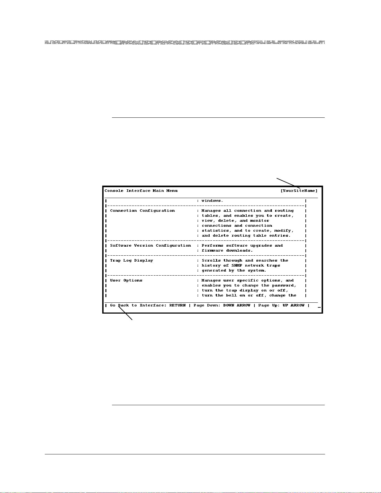
Chapter 1 Getting Started
Help Information
error codes and responses to commands. All responses and notifications are
recorded in a trap log. See Appendix A for details on displaying the trap log
and obtaining explanations of the trap messages.
To view the Help windows from the Console Interface Main Menu window,
perform the following procedure.
Viewing and Navigating the Help Windows
Begin
1 On the window for which help is desired, press the ? (question mark)
key.
The Help window for the current console window is displayed (see
Figure 1-1).
Your site name appears here
after initial conf igu r at io n
Information lin e
Figure 1-1. Main Menu Help Window
2 To display the remaining Help windows for the current console window,
press the Down Arrow key.
3 To scroll backward through the Help windows for the current console
window, press the Up Arrow key.
4 To exit Help and return to the current console window, press the Enter
key.
End
PacketStar® PSAX 1250 Multiservice Media Gateway User Guide, Issue 2 Release 8.0.0
1-6 255-700-247
Page 43

Technical Support
If you experience a problem with your PSAX 1250 system, refer to the Lucent
Technologies InterNetworking Systems Global Warranty, which accompanied your
shipment, for instructions on obtaining support in your area.
About Lucent Technologies
History
Lucent Technologies is the communications systems and technology company formed through the restructuring of AT&T. W e br ing with us a tra dition
of more than 125 years of experience and a dedication to superior customer
service.
Lucent Technologies manufactures, sells, and services a complete line of customer premises communications units, and commercial and multimedia
communications and messaging systems designed and supported by our
research and development unit, Bell Laboratories.
Our legacy and our spirit of innovation allow Lucent to provide our customers with the tools needed to communicate effectively, any time and anywhere, and to integrate the latest technologies into real-life solutions that
help make business work.
Chapter 1 Getting Started
Technical Support
For More Information
To learn more about the PacketStar PSAX family of Multiservice Media Gateways and the complete line of Lucent Technologies products, visit our Web
site at www.lucent.com.
About the PacketStar PSAX Product Family
Lucent Technologies provides a complete range of PSAX Multiservice Media
Gateways in the PacketStar PSAX family.
PSAX 1000 Multiservice Media Gateway
The PacketStar PSAX 1000 Multiservice Media Gateway is designed to provide
a full range of central office-based multiservice media gateway functions in a
small, competitively-priced package suitable for customer premise deployment. Ideal for central office, large enterprise, or wireless cell site multiservice media gateway applications, the PSAX 1000 system provides highly reliable network access for time-division multiplex voice, Frame Relay,
10/100Base-T Ethernet, and ATM data applications.
When it is functioning in a redundant operating mode and after it has experienced a single-point failure, the PSAX 1000 system provides up to 630 Mbps
of ATM cell bus capacity. The total ATM cell bus capacity of the system may
also be scaled to provide nonblocking, nonredundant chassis bandwidths
beyond 630 Mbps.
PacketStar® PSAX 1250 Multiservice Media Gateway User Guide, Issue 2 Release 8.0.0
255-700-247 1-7
Page 44

Chapter 1 Getting Started
About the PacketStar PSAX Product Family
Supporting four slots (19–inch chassis) for I/O and server modules—with a
full range of interfaces such as DS0A, DS1/E1, DS3/E3, OC-3, OC-3c/STM-1,
OC-12c/STM-4c, 10/100Base-T Ethernet, and serial—the PSAX 1000 system
is a cost-effective access switch solution for connecting to legacy equipment.
PSAX 1250 Multiservice Media Gateway
The PacketStar PSAX 1250 Multiservice Media Gateway is designed to provide
a full range of central office-based multiservice ATM access functions. Ideal
for the central office or a large enterprise’s multiservice media gateway, the
PSAX 1250 system provides highly reliable network access for time-division
multiplex voice, frame relay, 10/100Base-T Ethernet, and ATM data applications.
When it is functioning in a redundant operating mode and after it has experienced a single-point failure, the PSAX 1250 system provides up to 600 Mbps
of ATM cell bus capacity. The total ATM cell bus capacity of the system may
also be scaled to provide nonblocking, nonredundant chassis bandwidths
beyond 600 Mbps.
Supporting 10 slots (19-inch chassis) or 14 slots (23-inch chassis) for I/O and
server modules—with a full range of interfaces such as DS0A, DS1/E1,
DS3/E3, OC-3, OC-3c/STM-1, OC-12c/STM-4c, 10/100Base-T Ethernet, and
serial—the PSAX 1250 system is a cost-effective access switch solution for
interworking with legacy equipment.
PSAX 2300 Multiservice Media Gateway
The PacketStar PSAX 2300 Multiservice Media Gateway offers carrier-grade,
high-density multiserv ice A TM access functio ns. Designed a s the multi service
media gateway for the central office or for a large enterprise customer, the
PSAX 2300 system provides network access for time-division multiplex
voice, frame relay, 10/100Base-T Ethernet, and ATM data applications.
When it is functioning in a redundant operating mode and after it has experienced a single-point failure, the PSAX 2300 system provides up to 1.9 Gbps
of ATM cell bus capacity. The total ATM cell bus capacity of the system may
also be scaled to provide nonblocking, nonredundant chassis bandwidths
beyond 1.9 Gbps.
Supporting 15 slots for I/O and server modules—with provisions for OC-3,
OC-3c/STM- 1, and OC -1 2c /S TM -4 c in ter f ac es , N x T1/ E1 m o dul e pro te c ti o n
switching, and a full range of interfaces such as DS0A, DS1/E1, DS3/E3,
10/100Base-T Ethernet, and serial—the PSAX 2300 system solves demanding and diverse network design challenges with ease.
PSAX 4500 Multiservice Media Gateway
The PacketStar PSAX 4500 Multiservice Media Gateway provides carrier-class
reliability, with an unmatched range of service capabilities, end-to-end traffic
prioritization, “any-service, any-channel” flexibility, and breakthrough voice
technology. Ideal for the central office or a large enterprise multiservice
PacketStar® PSAX 1250 Multiservice Media Gateway User Guide, Issue 2 Release 8.0.0
1-8 255-700-247
Page 45

Chapter 1 Getting Started
Comments on This Guide
media gateway, the PSAX 4500 system provides highly reliable network
access for time-division multiplex voice, frame relay, 10/100Base-T Ethernet,
and ATM data applications.
When it is functioning in a redundant operating mode and after it has experienced a single-point failure, the PSAX 4500 system provides up to 4.2 Gbps
of ATM cell bus capacity. The total ATM cell bus capacity of the system may
also be scaled to provide nonblocking, nonredundant chassis bandwidths
beyond 4.2 Gbps.
The high-performance midplane design supports 15 interface slots. Module
protection for two groups of four or six multiport DS3, STS-1e, or E3 modules is provided via an N:1 protection scheme using rear access line interface
modules. The protection module provides backup so that on the failure of
any one of the modules in a group, traffic is maintained. A single PSAX 4500
system at the edge of the carrier network can transition traffic from a large
number of network customers over high-speed DS1/E1 IMA, DS3/E3, OC-3,
OC-3c/STM-4c, and OC-12c/STM-4c trunks into the ATM core, managing
the whole quickly and efficiently, down to the individual permanent virtual
circuit.
Through the use of the latest DSP voice technology, the PSAX 4500 system
supports advanced voice traffic over ATM (VToA) services for up to 6048 DS0
channels. As a multiservice media gateway—with H.248 call control, CAS,
PRI, GR-303, and V5.2 protocols, 3-Port DS3/STS-1e, 1-Port OC-3/STM-1
CES, and Tones and Announcements modules—the PSAX 4500 system provides packet solutions for voice over xDSL, trunking, tandem, and PRI offload
switching.
Comments on This Guide
To comment on the PacketStar® PSAX 1250 Multiser vice Media Gateway User
Guide, please complete the comment card that accompanied your shipment
and mail it to the following address:
Senior Manager, Information Design and Development Team
Lucent Technologies
PacketStar PSAX Products
8301 Professional Place
Landover, MD 20785
USA
You can also fax the comment card to us at: 301-809-4540.
PacketStar® PSAX 1250 Multiservice Media Gateway User Guide, Issue 2 Release 8.0.0
255-700-247 1-9
Page 46

Chapter 1 Getting Started
Comments on This Guide
PacketStar® PSAX 1250 Multiservice Media Gateway User Guide, Issue 2 Release 8.0.0
1-10 255-700-247
Page 47

2 Hardware Description
Overview of This Chapter
This chapter presents a description of the PacketStar PSAX 1250 Multiservice
Media Gateway system hardware.
System Features
The PacketStar PSAX 1250 Multiservice Media Gateway provides high-capacity, universal connectivity over an ATM wide area network (WAN).
Ideal for central office or large enterprise customer multi-services access concentration, the PSAX 1250 system provides highly reliable network access for
TDM voice, frame relay, and ATM data applications. The PSAX 1250 I/O
interfaces, which include 75 Bps to 30 Mbps serial, DS0A, T1/E1,
DS3/E3/STS-1e, OC-3, OC-3c/STM-1, Ethernet, and 2-Wire Station/Office,
are supported by a sophisticated package of features, such as PNNI (private
network-node interface), ILMI (integrated local management interface), 1+1
APS (automatic protection switching), trunk alarming, and a SS7 signaling
gateway interface. Echo cancellation and silence suppression features make
the PSAX 1250 system to a true multi-service platform. Featuring a 600 Mbps
ATM cell bus capacity, carrier-class reliability, the PSAX 1250 system is a costeffective access switch solution for connecting to legacy equipment.
System Hardware Components
The PSAX 1250 Multiservice Media Gateway base systems include the following hardware components:
• 19-inch chassis (see Figure 2-1):
~ Chassis—48.26-cm (19-in.) chassis with mounting brackets for 48.26 cm
(19 in.) or 58.2 cm (23 in.) equipment racks
~ Power Supply modules: 110 Vac, 220 V ac, or -48 V dc—two each for
redundant operation
For AC Power Supply modules, agency-approved AC power cordsets
must be ordered separately with the chassis.
~ Stratum 3–4 module—two each for redundant operation
PacketStar® PSAX 1250 Multiservice Media Gateway User Guide, Issue 2 Release 8.0.0
255-700-247 2-1
Page 48
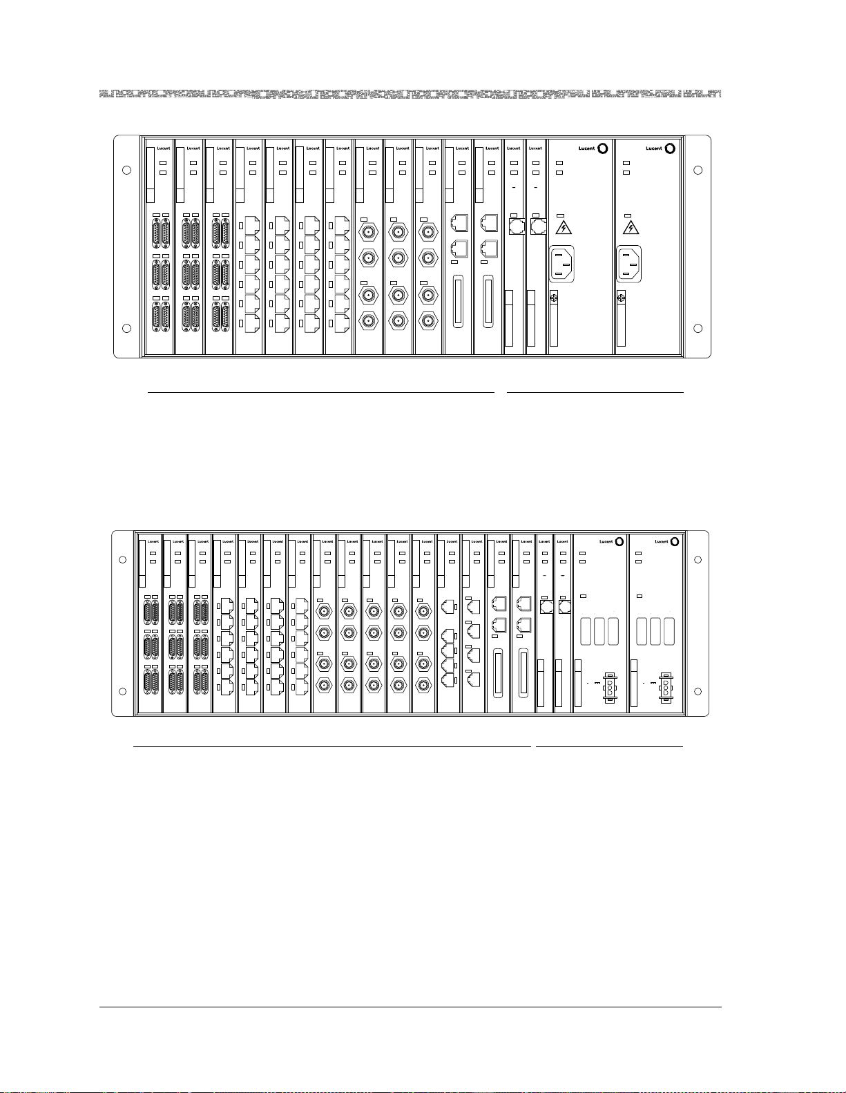
Chapter 2 Hardware Description
System Hardware Components
FAIL
FAIL
FAIL
ACTIVE
ACTIVE
ACTIVE
SERIAL SERIAL SERIAL
1
2
1
2
1
2
3
4
3
4
5
6
5
6
1
234567891011122122 23 24
LOS
1
2
3
4
3
4
5
6
5
6
FAIL
ACTIVE
DS1
IMA
FAIL
ACTIVE
DS1
IMA
LOS
1
1
2
2
3
3
4
4
5
5
6
6
FAIL
FAIL
ACTIVE
ACTIVE
DS1
DS1
IMA
IMA
LOS
LOS
1
2
3
4
5
6
FAIL
FAIL
ACTIVE
ACTIVE
E3
E3
ATM
ATM
LOS
LOS
TX
TX
RX
RX
LOS
LOS
TX
TX
RX
RX
FAIL
FAIL
ACTIVE
ACTIVE
CPU
E3
ATM
ETHERNET
LOS
TX
CONSOLE
RX
TX
RX
LOAD
KEY KEY
LOS
Slots for User-Selected I/O Modules
Figure 2-1. PacketStar® PSAX Multiservice Media Gateways (19-in.)
• 23-inch chassis (see Figure 2-2):
~ Chassis—58.42-cm (23-in.) chassis with mounting brackets for 58.2 cm
(23 in.) equipment racks (installation kit includes brackets)
~ Power Supply module: -48 V dc—two each for redundant operation
~ Stratum 3–4 module—two each for redundant operation
FAIL
ACTIVE
CPU
ETHERNET
CONSOLE
LOAD
FAIL
ACTIVE
STRATUM
3 4
CLK LOS
ACTIVE
STRATUM
3 4
CLK LOS
ACTIVE
Power Supply
( AC )
non-redundant
DANGER:
HIGH VOLTAGE
AC INPUT
50/60 Hz
100-127 V ~ 5.0 A
200-250 V ~ 2.5 A
FAIL
FAIL
Common Equipment Slots
WARNINGS:
SEE INSTALLATION
INSTRUCTIONS BEFORE
CONNECTING THIS MODULE
ENSURE FACILITY POWER
IS COMPATIBLE WITH
VOLTAGE RATING OF
THIS MODULE
ATTACH POWER
CORD ONLY
WHEN UNIT IS
FULLY SEATED
IN CHASSIS
UNPLUG POWER CORD
BEFORE REMOVING
THIS MODULE
MULTIPLE POWER
CONNECTIONS,
DISCONNECT TWO
POWER CORDS
BEFORE SERVICING
CHASSIS
FAIL
ACTIVE
Power Supply
( AC )
non-redundant
DANGER:
HIGH VOLTAGE
AC INPUT
50/60 Hz
100-127 V ~ 5.0 A
200-250 V ~ 2.5 A
WARNINGS:
SEE INSTALLATION
INSTRUCTIONS BEFORE
CONNECTING THIS MODULE
ENSURE FACILITY POWER
IS COMPATIBLE WITH
VOLTAGE RATING OF
THIS MODULE
ATTACH POWER
CORD ONLY
WHEN UNIT IS
FULLY SEATED
IN CHASSIS
UNPLUG POWER CORD
BEFORE REMOVING
THIS MODULE
MULTIPLE POWER
CONNECTIONS,
DISCONNECT TWO
POWER CORDS
BEFORE SERVICING
CHASSIS
FAIL
FAIL
FAIL
ACTIVE
SERIAL SERIAL
1
2
3
4
5
6
1
FAIL
1
3
5
FAIL
ACTIVE
ACTIVE
DS1
SERIAL
IMA
1
2
2
LOS
1
2
3
4
4
3
4
5
6
6
5
6
DS1
DS1
IMA
IMA
LOS
LOS
1
1
2
2
3
3
4
4
5
5
6
6
E3
DS1
ATM
IMA
LOS
LOS
TX
1
2
RX
3
LOS
4
TX
5
RX
6
ACTIVE
ACTIVE
ACTIVE
ACTIVE
ACTIVE
ACTIVE
ACTIVE
E3
E3
ATM
ATM
LOS
LOS
TX
TX
RX
RX
LOS
LOS
TX
TX
RX
RX
2 3 4 5 6 7 8 9 10 11 12 13 14 15
FAIL
FAIL
FAIL
FAIL
FAIL
FAIL
FAIL
ACTIVE
ACTIVE
E3
E3
ATM
ATM
LOS
LOS
TX
TX
RX
RX
LOS
LOS
TX
TX
RX
RX
FAIL
FAIL
ACTIVE
ACTIVE
VOICE
ENET
2WO
1
1
2
2
3
3
4
4
4
Slots for User-Selected I/O Modules
Figure 2-2. PacketStar® PSAX Multiservice Media Gateways (23-in.)
The following items are ordered separately to complete the configuration of
the PSAX 1250 system:
• Central processing unit (CPU2) module with the appropriately installed
system software release. One is required for nonredundant operation. Two
are required for active/standby operation. (see your Lucent Te chnologies
sales representative for ordering information)
• Input/output (I/O) and server modules (see your Lucent Technologies sales
representative for ordering information).
• Blank facepla te module s—re qu ire d for emp ty I/O and se rv er slot s
FAIL
ACTIVE
ETHERNET
CONSOLE
LOAD
LOAD
KEY
KEY
FAIL
FAIL
FAIL
ACTIVE
ACTIVE
CPUCPU
ETHERNET
CONSOLE
LOAD
KEY
16
Power Supply
STRATUM
STRATUM
( -48 VDC )
3 4
3 4
non-redundant
CLK LOS
CLK LOS
CAUTION:
DISCONNECT POWER BEFORE CHANGING FUSE.
REPLACE ONLY WITH SAME TYPE AND RATING OF FUSE.
ATTENTION:
COUPER LE COURANT AVANT DE REMPLACER
LE FUSIBLE. REMPLACER PAR UN FUSIBLE DE MEME TYPE
ET DE MEMES CARACTERISTIQUES NOMINALES.
7.5 A 7.5 A 7.5 A
ATTACH POWER CABLE
ONLY WHEN UNIT IS FULLY
SEATED IN CHASSIS
48V
RETURN
FRAME
21 22 23 24
Common Equipment Slots
FAILFAIL
ACTIVEACTIVEACTIVE
Power Supply
( -48 VDC )
non-redundant
CAUTION:
DISCONNECT POWER BEFORE CHANGING FUSE.
REPLACE ONLY WITH SAME TYPE AND RATING OF FUSE.
ATTENTION:
COUPER LE COURANT AVANT DE REMPLACER
LE FUSIBLE. REMPLACER PAR UN FUSIBLE DE MEME TYPE
ET DE MEMES CARACTERISTIQUES NOMINALES.
7.5 A 7.5 A 7.5 A
ATTACH POWER CABLE
ONLY WHEN UNIT IS FULLY
SEATED IN CHASSIS
48V
RETURN
FRAME
PacketStar® PSAX 1250 Multiservice Media Gateway User Guide, Issue 2 Release 8.0.0
2-2 255-700-247
Page 49

• PSAX 1250 Fan Tray chassis is required to maintain proper air flow
through the PSAX 1250 chassis. A 48.26-cm (19-in.) chassis with ac or dc
input power is available for the 48.26-cm (19-in.) PSAX 1250 chassis. A
58.42-cm (23-in.) chassis with dc input power is available for the 58.42-cm
(23-in.) PSAX 1250 chassis (see your Lucent Technologies sales representative for ordering information).
Functional Description
Chassis
The PSAX 1250 system can support either one or two Stratum 3–4 modules,
one or two power supply modules, and one or two CPU2 modules, to obtain
the desired redundancy of common system equipment.
The PSAX 1250 chassis consists of a slotted shelf, a backplane, two side
pieces, and two honeycomb-patterned, electromagnetic interference (EMI)
shields as the top and the bottom pieces. The chassis is available in 48.26-cm
(19-in.) or 58.42-cm (23-in.) widths to fit standard equipment racks or telco
frames. The 23-inch chassis supports only a -48 V dc power supply (not
110/220 V ac).
Chapter 2 Hardware Description
Functional Description
For mounting in a rack or frame, the chassis is shipped with mounting angle
brackets attached to the sides. These brackets can be attached at three different positions on the side pieces to mount the chassis in different horizontal
positions in a rack.
Module Slot Locations
The 48.26-cm (19-in.) PSAX 1250 chassis has 16 slots; the 58.42-cm (23-in.)
chassis has 20 slots. In both sizes, four slots are reserved for the optionally
redundant power supplies and the optionally redundant Stratum 3–4 modules. The remaining 12 or 16 slots can be filled with one or two CPU2 modules and various I/O and server modules, selected on the basis of access concentration requirements.
The module slots in the PSAX 1250 system are numbered from left to right:
• Slots 1 through 12 (48.26-cm/19-in. chassis) or slots 1 through 16 (58.42cm/23-in. chassis) are provided for the CPU2 modules and the userselected I/O and server modules
~ In the 48.26-cm (19-in.) chassis, the CPU2 modules can be placed in any
~ In the 58.42-cm (23-in.) chassis, the CPU2 modules can be placed in any
• Slots 21 and 22 contain the Stratum 3–4 modules
• Slots 23 and 24 contain the Power supply modules
unreserved (1 through 12) slot, but usually are placed in slots 11 and 12
(or just in slot 12 for a single-CPU2 configuration)
unreserved (1 through 16) slot, but usually are placed in slots 15 and 16
(or just in slot 16 for a single-CPU2 configuration, because I/O modules
cannot be used in slot 16)
PacketStar® PSAX 1250 Multiservice Media Gateway User Guide, Issue 2 Release 8.0.0
255-700-247 2-3
Page 50
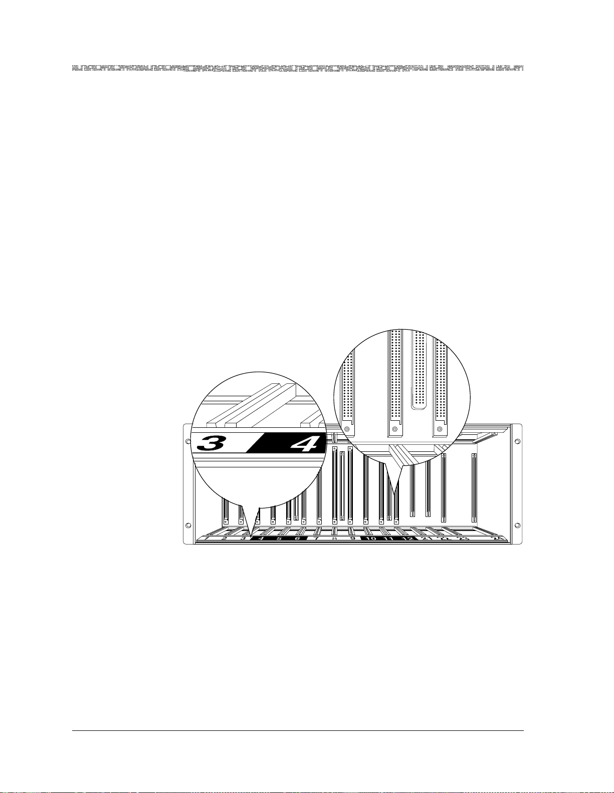
Chapter 2 Hardware Description
Functional Description
If redundant Stratum 3–4 and Power supply modules are not used, the slots
designated for these modules must remain empty. Blank faceplates are
required in all empty slots.
Backplane
The chassis backplane distributes data, clock signals, and power to the modules. The dual-bus (A/B) architecture of the backplane provides several layers of protection for system resources and functionality. In conjunction with
the Stratum 3–4 modules, this architecture provides the basic ATM concentration technologies of the PSAX 1250 system. The dual-bus design provides
1.2 Gbps total bandwidth and allows live (power-supplied) insertion of primary and redundant common equipment modules, and input/output and
server modules. The backplane is based entirely on switching ATM cells.
Figure 2-3 shows a 48.26-cm (19-in.) PSAX 1250 chassis with no modules
installed. Note the enlarged insets showing the backplane connectors for the
modules at the back of the chassis and the slot numbers at the front of the
chassis.
Figure 2-3. PSAX 1250 48.26-cm (19-in.) Chassis Backplane
Figure 2-4 shows a 58.42-cm (23-in.) PSAX 1250 chassis with no modules
installed.
PacketStar® PSAX 1250 Multiservice Media Gateway User Guide, Issue 2 Release 8.0.0
2-4 255-700-247
Page 51
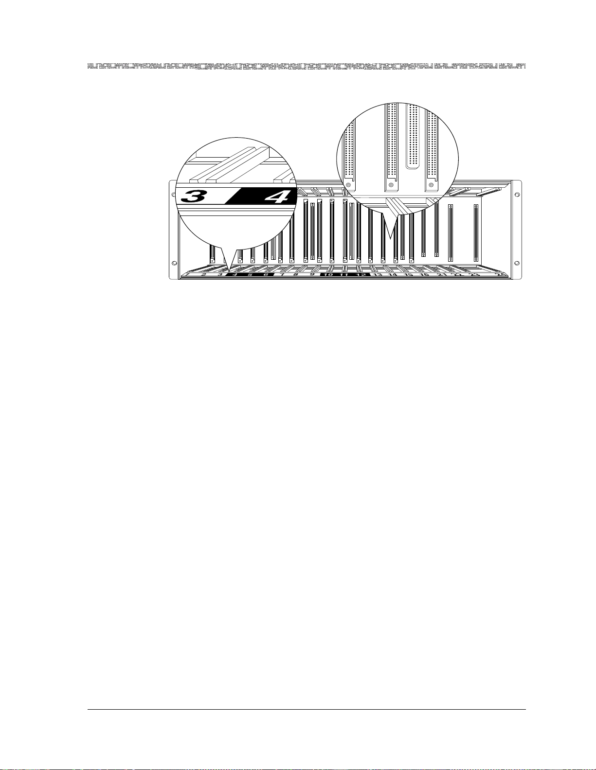
Figure 2-4. PSAX 1250 58.42-cm (23-in.) Chassis Backplane
Power Supply Modules
Chapter 2 Hardware Description
Functional Description
Three types of power supply modules are available for the PSAX 1250:
• 110 V ac Power Supply module (supports only the 19-inch chassis)
• 220 V ac Power Supply module (supports only the 19-inch chassis)
• -48 V dc Power Supply module (supports both chassis)
The Power Supply modules (see Figure 2-5) distribute power to the backplane and all of the modules in the chassis. Slots 23 and 24 are reserved for
the Power Supply modules. Each module includes status indicators and a
power connection. The -48 V dc Power Supply module includes inline circuit
protection on the faceplate. When using the AC Power Supply modules, circuit protection must be supplied by the customer.
Note: In order to u se the 22 0 Vac Power Supply module , you mus t orde r
a suitable AC power cordset for use in your geographic location.
For your convenience, Lucent Technologies has made a variety of
international cordsets available for ordering. See your Lucent Technologies representative for ordering details.
In a redundant configuration, two power supply modules operate in a loadsharing mode to increase system reliability . This configuration ensures that as
long as one power supply module is active, all other modules are fully powered. When two power supply modules are installed, each normally runs at
one-half of its capacity. If one fails, the other Power Supply module takes
over completely.
Note: A single 110 or 220 V ac power supply module may not fully
power the chassis, depending on which I/O modules are being
used.
PacketStar® PSAX 1250 Multiservice Media Gateway User Guide, Issue 2 Release 8.0.0
255-700-247 2-5
Page 52
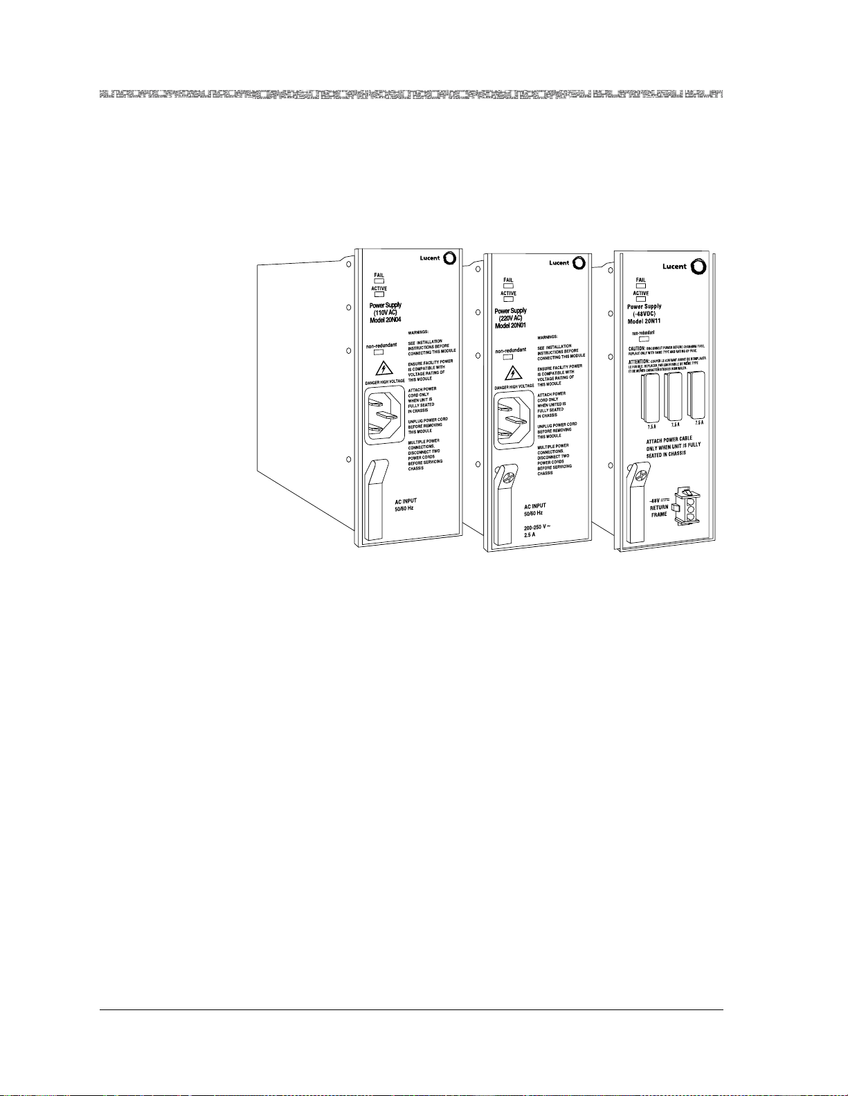
Chapter 2 Hardware Description
Functional Description
When the PSAX 1250 chassis is configured to operate in a -48 V dc environment, the -48 V dc power is supplied through the PSAX 1250 Fan Tray power
supply cabling.
Three LED indicators on the faceplate provide status indications of the mod-
®
ule. Refer to the PacketStar
PSAX 1250 Multiservice Media Gateway Installation
Guide for additional information.
Figure 2-5. PSAX 1250 110 Vac, 220 Vac, and -48 V dc Power Supply Modules
Stratum 3–4 Module
Two types of Stratum 3–4 modules are available: ITU-compliant Stratum 3–4
and ANSI-compliant Stratum 3–4. The difference in the modules is the level
of the composite clock input. The jack on the faceplate of the ITU-compliant
Stratum 3–4 accepts the signal level in the ITU spectrum. The jack on the
faceplate of the ANSI-compliant Stratum 3–4 accepts the signal level in the
ANSI mask.
The Stratum 3–4 modules provide synchronization and common equipment
monitoring for the PSAX 1250 system. Each Stratum 3–4 module supports a
single bus and furnishes 600 Mbps of ATM bandwidth. Although the system
can operate with one Stratum 3–4 module, two (in slots 21 and 22) yield the
maximum system throughput of 1.2 Gbps and offer redundancy to protect
service in case one module fails. With both Stratum 3–4 modules in service,
the I/O modules use both backplane buses. If one Stratum 3–4 module fails,
all the I/O modules use the bus from the remaining Stratum 3–4 module, but
system throughput is reduced by half, that is, to 600 Mbps.
In addition, the PSAX 1250 system can obtain network clock synchronization
from any of its interfaces except for the DSP2A Voice Server, DSP2B Voice
Server, DSP2C Voice Server, Voice 2-Wire Station, Voice 2-Wire Office and
Ethernet modules. With the ability to accept a timing reference from any
physical interface at low transmission rates, the system provides the network
PacketStar® PSAX 1250 Multiservice Media Gateway User Guide, Issue 2 Release 8.0.0
2-6 255-700-247
Page 53

CPU2 Module
Chapter 2 Hardware Description
Hardware Specifications
with a reliable transpor t and access infrastructure. The Stratum 3–4 module
is accurate to Stratum 3 requirements, allowing the PSAX 1250 system to run
even after losing external synchronization, for as long as 24 hours without
synchronization problems.
Operating in a nonload-sharing, active/standby mode, the CPU2 module provides the processing, switchi ng, and storage functions for the system. With a
RISC-based microprocessor, the module has the processing power to maintain data flow, perform numerical calculations, and manage the direct memory access (DMA) interfaces. The processor perfo rm s the int erfa c e- sp ec if ic
physical and link layer protocol functions, in addition to the queuing and
traffic manage ment func tion s bein g perf orme d on the vario us I/ O and ser ver
modules. The module has 128 MB of memory for routing and signaling functions, forward error correction, processing SVC connections, and managing
network capabilities.
SVC retention pr eserves ac tive ATM switched virtual conn ections (S VCs) and
switched permanent virtual connections (SPVCs). However, virtual connections on calls in a transient state will not be saved. To preserve active virtual
connections, do not remove the active module while it is synchronizing with
the redundant module.
In a redundant configuration, when you upgrade or remove the active module, the standby (backup) module now becomes the active module, and the
original active module becomes the standby module. This switchover is
designed to minimize the time the equipment is down.
The standby module supports complete console and SNMP interfaces, in the
same way the active module supports them, except that the standby module
blocks all set operations.
Hardware Specifications
Chassis Specifications
The specifications for the PSAX 1250 chassis are given in Table 2-1.
PacketStar® PSAX 1250 Multiservice Media Gateway User Guide, Issue 2 Release 8.0.0
255-700-247 2-7
Page 54

Chapter 2 Hardware Description
Hardware Specifications
Table 2-1. Chassis Hardware Specifications
Specification Description
Slot configuration 48.26-cm (19-in.) chassis: 16 slots total—12 slots for
Dimensions
Weight
Material Aluminum
Color Black
Cooling method Forced air through the PSAX 1250 Fan Tray
CPU modules and user-selected I/O and server
modules
58.42-cm (23-in.) chassis: 20 slots total—16 slots for
CPU modules and user-selected I/O and server
modules
Both chassis: 2 reserved slots for Stratum 3–4
modules
2 reserved slots for power supply modules
48.26-cm (19-in.) chassis: 48.26 cm (19 in.) wide x
26.67 cm (10.5 in.) deep x 17.78 cm (7 in.) high
58.42-cm (23-in.) chassis: 58.42 cm (23 in.) wide x
26.67-cm (10.5 in.) deep x 17.78 cm (7 in.) high
48.26-cm (19-in.) chassis: 4.09 kg (9 lb) empty and
approximately 13.62 kg (30 lb) fully populated
58.42-cm (23-in.) chassis: 5.4 5 kg (12 lb) empty and
approximately 15.89 kg (35 lb) fully populated
System Environmental Speci fica tions
The environmental specifications for the PSAX 1250 chassis are given in
Table 2-2.
Table 2-2. System Environmental Specifications
Specification Description
Operating temperature r ange 0° to 50° C (32° to 122° F)
Operating humidity range 5% to 85% relative humidity
Operating altitude range 197 feet below sea level to 13,123 feet above sea
level
Storage temperature range -40° to 70° C (-40° to 158° F)
Storage humidity range 0 to 90% noncondensing
Power Supply Module Specifications
Three Power Supply modules are available for the PSAX 1250 system:
• 110 V ac Power Supply module (supports only the 19-inch chassis)
• 220 V ac Power Supply module (supports only the 19-inch chassis)
• -48 V dc Power Supply module (supports both chassis)
PacketStar® PSAX 1250 Multiservice Media Gateway User Guide, Issue 2 Release 8.0.0
2-8 255-700-247
Page 55

Chapter 2 Hardware Description
Hardware Specifications
The specifications for each module are described in the following sections.
When preparing to install a chassis with redundant Power Supply modules,
the modules normally operate in a load-sharing mode. This means that the
maximum current required for the chassis is the maximum rated current
specified for one Power Supply module, not the combined total for both
modules.
110 V ac Power Supply
Table 2-3. 110 V ac Power Supply Module Specifications
The specifications for the PSAX 1250 110 V ac Power Supply module are
found in Table 2-3.
Specification Description
Slot configuration Slot 23 or 24 or both (for redundancy)
Input power Voltage range: 100 to 125 V ac at 50 to 60 Hz
Rated current: 5 A maximum per module
Maximum power: 300 W maximum per chassis
(1023.6 BTU/hr)
Circuit protection: Customer supplied
Dimensions 15.75 cm H x 24.13 cm D x 5.4 cm W
(6.2 in. H x 9.5 in. D x 2.125 in. W)
Weight 1.14 kg (2.5 lb.)
Units per system Two recommended for redundancy
Connector One recessed 3-pin connector on faceplate
(IEC 60320)
Wiring/Cabling Requires agency-approved AC power cordset
220 V ac Power Supply
The specifications for the PSAX 1250 220 V ac Power Supply module are
found in Table 2-4.
Table 2-4. 220 V ac Power Supply Module Specifications
Specification Description
Slot configuration Slot 23 or 24 or both (for redundancy)
Input power
Voltage range: 200 to 250 V ac at 50 to 60 Hz
Rated current: 2.5 A maximum per module
Maximum power: 300 W maximum per chassis
(1023.6 BTU/hr)
Circuit protection: customer supplied
Dimensions 15.75 cm H x 24.13 cm D x 5.4 cm W
(6.2 in. H x 9.5 in. D x 2.125 in. W)
Weight 1.14 kg (2.5 lb.)
Units per system Two recommended for redundancy
Connector One recessed 3-pin connector on faceplate
(IEC 60320)
Wiring/Cabling Requires agency-approved AC power cordset
PacketStar® PSAX 1250 Multiservice Media Gateway User Guide, Issue 2 Release 8.0.0
255-700-247 2-9
Page 56

Chapter 2 Hardware Description
Hardware Specifications
-48 V dc Power Supply
Table 2-5. -48 V dc Power Supply Module Specifications
The specifications for the PSAX 1250 -48 V dc Power Supply module are
found in Ta ble 2-5.
Specification Description
Slot configuration Slot 23 or 24 or both (for redundant configuration)
Input power
Voltage range: -48 V dc
Rated current: 7.0 A maximum per module for the
19 in. chassis and 9.0 A maximum per module for
the 23 in. chassis
Maximum power: 360 W maximum per 19 in.
chassis (1228.3 BTU/hr) and 430 W maximum per
23 in. chassis (1467.2 BTU/hr)
Circuit protection: Three 7.5 A, wire-type fast act-
ing black/white, alarm indicating, fuses
Dimensions 17.3 cm H x 23.3 cm D x 5.4 cm W
(6.8 in. H x 9.2 in. D x 2.126 in. W)
Weight 1.14 kg (2.5 lb)
Units per system Two recommended for redundancy
Connector One 3-pin female connector on the faceplate
Wiring/Cabling Supplied through the PSAX 1250 Fan Tray.
Stratum 3–4 Module Specifications
The specifications for the PSAX 1250 Stratum 3–4 module are given in
Table 2-6.
Table 2-6. Stratum 3–4 Module Specifications
Specification Description
Slot configuration Slot 21 or 22 or both (for redundant configuration)
Dimensions 15.75 cm H x 1.78 cm W x 24.13 cm D
(6.2 in. H x 0.7 in. W x 9.5 in. D)
Weight 0.02 k g (0.4 75 lb)
Units per system 2 recommended (redundant)
Power consumption 14 W per pair
Synchronization source Line, internal, or external
Accuracy Stratum 3 or 4, selectable
External clock input ANSI Composite (8 kHz), ITU-T Composite (8 kHz),
T1BITS (1.544 MHz), and E1ETSI (2.048 MHz).
Connector One RJ-12 (with either 120 ohm or 75 ohm termination)
PacketStar® PSAX 1250 Multiservice Media Gateway User Guide, Issue 2 Release 8.0.0
2-10 255-700-247
Page 57

CPU2 Module Specifications
The specifications for the CPU2 module are given in Table 2-7.
Table 2-7. CPU2 Module Specifications
Specification Description
Slot configuration Slots 11 and 12 (19-in.) or Slots 15 and 16 (23-in.)
Dimensions 17.3 cm H x 2.4 cm W x 24.1 cm D
Weight 0.45 kg (1 lb)
Units per system 1 for nonredundant operation and 2 for redundant
Power consumption 18 W, average
Processing RISC microprocessor
Memory 140 MB flash drive
Connectors One RJ-45 connector labeled
Chapter 2 Hardware Description
(6.8 in. H x 0.95 in. W x 9.5 in. D)
operation
128 MB RAM
ETHERNET and one
RJ-12 connector labeled
CONSOLE
Hardware Specifications
PacketStar I/O and Server Module Hardware Specifications
Table 2-8 shows the genera l physi c al hardware and environme n tal spec ifi cations for the PacketStar PSAX I/O and server modules.
Table 2-8. Physical Hardware Specifications for the PacketStar PSAX I/O and the Server Modules
Specification Description
Dimensions 17.3 cm H x 2.41 cm W x 23.2 cm D
(6.8 in. H x 0.95 in. W x 9.13 in. D)
Weight 0.45 kg (1.0 lb.)
Additional information can be found in the appropriate PacketStar PSAX
module user guides.
Module Performance and Power Specifications
Chassis speed, power consumption, and memory allocation specifications for
each PacketStar PSAX module are described in T able 2-9. A functional description for each I/O and server module can be found in Appendix E.
PacketStar® PSAX 1250 Multiservice Media Gateway User Guide, Issue 2 Release 8.0.0
255-700-247 2-11
Page 58

Chapter 2 Hardware Description
Hardware Specifications
Table 2-9. Performance and Power Specifications for the PSAX Modules
Module
6-Port DS1 IMA (IMA
DS1
)
6-Port Enhanced
DS1/T1 Multiservice
DS1/T1 Enh)
(
Total
Amount of
SDRAM
16 MB 8 MB 1 MB 7 MB
16 MB 8 MB 1 MB 7 MB
Module
Program and
Data Space
DS1/T1 Interface Modules
Maximum
Input
*
Buffer
(114,688)
(114,688)
Output
Buffer
Chassis
Speed
Low
Speed
Low
Speed
†
Power
Consumption
18 W
18 W
12-Port MediumDensity DS1
Multiservice (
MD DS1)
12-Port
Medium-Density
DS1/E1/DS0A CES
MD DS1/E1/DS0A CES)
(
12-Port
Medium-Density DS1
MD DS1 IMA)
IMA (
6-Port E1 IMA (IMA E1)
6-Port Enhanced E1
Multiservice (
E1 Enh)
21-Port High-Density
E1 Multiservice (HD E1)
21-Port High-Density
E1 IMA (HD E 1 IMA)
1-Port Channelized
DS3 Multiservice (
DS3
)
CH
24 MB 7 MB 4 MB 13 MB
(212,992)
8 MB 8 MB 2 cells/
port
16 cells/
port
24 MB 7 MB 4 MB 13 MB
(212,992)
E1 Interface Modules
16 MB 8 MB 1 MB 7 MB
(114,688)
16 MB 8 MB 1 MB 7 MB
(114,688)
24 MB 7 MB 4 MB 13 MB
(212,992)
24 MB 7 MB 4 MB 13 MB
(212,992)
DS3, E3, and STS-1e Interface Modules
24 MB 7 MB 4 MB 13 MB
(212,992)
Low
Speed
High
Speed
Low
Speed
Low
Speed
Low
Speed
Low
Speed
Low
Speed
Low
Speed
14.5 W
11.5 W
14.5 W
18 W
18 W
14.5 W
14.5 W
13 W
1-Port Channelized
DS3 CES (CH DS3)
1-Port DS3 IMA (
IMA
)
DS3
1-Port Unchannelized
DS3 Frame Relay (DS3
FR
)
2-Port DS3 ATM (
ATM
)
PacketStar® PSAX 1250 Multiservice Media Gateway User Guide, Issue 2 Release 8.0.0
2-12 255-700-247
DS3
24 MB 7 MB 4 MB 13 MB
(212,992)
24 MB 7 MB 4 MB 13 MB
(212,992)
8MB 4MB 1MB 4MB
(65,536)
8MB 3MB 1MB 4MB
(65,536)
Low
Speed
Low
Speed
Low
Speed
Low
Speed
13 W
13 W
13 W
15 W
Page 59

Chapter 2 Hardware Description
Table 2-9. Performance and Power Specifications for the PSAX Modules (Continued)
Hardware Specifications
Module
2-Port E3 ATM (E3
ATM
)
3-Port Channelized
DS3/STS-1e CES (CH
DS3/STS-1e
)
3-Port DS3/E3 ATM
(DS3/E3 ATM)
3-Port Unstructured
DS3/E3 CES (
DS3/E3 CES
UNSTR
)
1-Port Channelized
STS-1e, T1 Format (CH
STS-1e T1
)
1-Port Channelized
OC-3/STM-1 CES
Multimode (
OC-3/STM-1 CES MM
CH
)
Total
Amount of
SDRAM
Module
Program and
Data Space
Maximum
Input
*
Buffer
Output
Buffer
8MB 3MB 1MB 4MB
(65,536)
8 MB 8 MB 2 cells/
port
16 cells/
port
72MB 8MB 32MB 32MB
(524,288)
N/A 8 MB 2 cells/
port
16 cells/
port
24 MB 7 MB 4 MB 13 MB
(212,992)
Fiber-Optic Interface Modules
8MB 8MB 2cells/
port
16 cells/
port
Chassis
Speed
Low
Speed
High
Speed
High
Speed
High
Speed
Low
Speed
High
Speed
†
Power
Consumption
17 watts
15 W
17 W
12 W
7 W
13 W
1-Port OC-3c
Multimode with
AQueMan (
AQ)
)
OC-3c (MM
1-Port OC-3c
Single-Mode with
AQueMan (
AQ)
)
OC-3c (SM
1-Port OC-3c
Multimode with Traffic
Shaping (
TS)
OC-3c (MM
)
1-Port OC-3c
Single-Mode with
Traffic Shaping (
(SM TS)
)
OC-3c
1-Port OC-3c 1+1 APS
Multimode (OC-3c MM
APS
)
1-Port OC-3c 1+1 APS
Single-Mode (OC-3c SM
APS
)
8 MB 3 MB 2.5 MB 2.5 MB
(40,960)
8 MB 3 MB 2.5 MB 2.5 MB
(40,960)
8MB 3MB 3MB 2MB
(32,768)
8MB 3MB 3MB 2MB
(32,768)
32MB 8MB 12MB 12MB
(196,608)
32MB 8MB 12MB 12MB
(196,608)
Low
Speed
Low
Speed
Low
Speed
Low
Speed
Low
Speed
Low
Speed
15 W
15 W
15 W
15 W
11.5 W
11.5 W
PacketStar® PSAX 1250 Multiservice Media Gateway User Guide, Issue 2 Release 8.0.0
255-700-247 2-13
Page 60

Chapter 2 Hardware Description
Hardware Specifications
Table 2-9. Performance and Power Specifications for the PSAX Modules (Continued)
Module
1-Port STM-1
Multimode with
AQueMan (
AQ)
)
STM-1 (MM
1-Port STM-1
Single-Mode with
AQueMan (
AQ)
)
STM-1 (SM
1-Port STM-1
Multimode with Traffic
Shaping (
TS)
STM-1 (MM
)
1-Port STM-1
Single-Mode with
Traffic Shaping (
(SM TS)
)
STM-1
1-Port STM-1 1+1 MSP
Multimode (STM-1 MM
MSP
)
Total
Amount of
SDRAM
Module
Program and
Data Space
Maximum
Input
*
Buffer
Output
Buffer
8 MB 3 MB 2.5 MB 2.5 MB
(40,960)
8 MB 3 MB 2.5 MB 2.5 MB
(40,960)
8MB 3MB 3MB 2MB
(32,768)
8MB 3MB 3MB 2MB
(32,768)
32MB 8MB 12MB 12MB
(196,608)
Chassis
Speed
Low
Speed
Low
Speed
Low
Speed
Low
Speed
Low
Speed
†
Power
Consumption
15 W
15 W
15 W
15 W
11.5 W
1-Port STM-1 1+1 MSP
Single-Mode (STM-1
SM MSP
)
1-Port OC-12c/STM-4c
Multimode
OC-12c/STM-4c MM)
(
(not in 23” chassis,
conditional in 19”)
4-Port Voice 2-Wire
Office (
VOICE 2WO)
8-Port Voice 2-Wire
Station (
VOICE 2WS)
2-Port High Speed
HIGH SPEED)
(
Quadserial (
SERIAL
QUAD
)
6-Port Multiserial
SERIAL)
(
32MB 8MB 12MB 12MB
(196,608)
72 MB 8 MB
(SDRAM)
32 MB 32 MB
(524,288)
Low
Speed
High
Speed
1MB
(SRAM)
2-Wire Interface Modules
8MB 4MB N/A N/A Low
Speed
8MB 4MB N/A N/A Low
Speed
Serial Interface Modules
8MB 3MB 1MB 4MB
(65,536)
24 MB 7 MB 4 MB 13 MB
(212,992)
8MB 3MB 1MB 4MB
(65,536)
Low
Speed
Low
Speed
Low
Speed
11.5 W
13 W
14 W
15 W
20 W
15 W
15 W
PacketStar® PSAX 1250 Multiservice Media Gateway User Guide, Issue 2 Release 8.0.0
2-14 255-700-247
Page 61

Chapter 2 Hardware Description
Table 2-9. Performance and Power Specifications for the PSAX Modules (Continued)
Hardware Specifications
Module
4-Port Ethernet (ENET)
Etherne t (
ENET)
DSP2C Voice Server
DSP2C)
(
DSP2D Voice Server
DSP2D)
(
DSP2E Voice Server
DSP2E)
(
DSP2F Voice Server
DSP2F)
(
Route Server (ROUTE
SERVER
)
Tones and
Announcements
Server (
TAS)
Total
Amount of
SDRAM
Module
Program and
Data Space
Ethernet Interface Modules
Maximum
Input
*
Buffer
Output
Buffer
Chassis
Speed
32MB 8MB 24MB N/A High
Speed
64 MB 8 MB 4 MB 4 MB
(65,536)
DSP2 Voice Servers
1MB
(SRAM)
2MB
512 KB
N/A N/A Low
(SRAM)
2MB N/A N/A High
(SRAM)
2MB
2MB N/A N/A High
(SRAM)
2MB
2MB N/A N/A High
(SRAM)
Other Server Modules
Low
Speed
Speed
Speed
Speed
Speed
64 MB 8 MB N/A N/A Low
Speed
1MB
(SRAM)
512 KB
(SRAM)
N/A N/A Low
Speed
†
Power
Consumption
16–17 W
13 W
16 W
17 W
15 W
13 W
13 W
15 W
Common Equipment Modules
Alarm (ALARM)
* The I/O buffers carry 16,384 cells per megabyte for all PSAX modules except the 4-Port Voice 2-Wire
Office module, the 8-Port Voice 2-Wire Station module, and the DSP2
have no cells carried on the I/O buffers.
† This column relates only to the speed at which the modules communicate within the chassis. A high-
speed module will communicate at high speed (1.23 Gbps) in a chassis that has a high-speed bus
(PSAX 4500 chassis). High-speed modules will communicate at 650 Mbps in any other chassis. Lowspeed modules will always communicate at 650 Mbps in any chassis.
PacketStar® PSAX 1250 Multiservice Media Gateway User Guide, Issue 2 Release 8.0.0
255-700-247 2-15
N/A N/A N/A N/A N/A 3 W
x Voice Server modules, which
Page 62

Chapter 2 Hardware Description
Hardware Specifications
PacketStar® PSAX 1250 Multiservice Media Gateway User Guide, Issue 2 Release 8.0.0
2-16 255-700-247
Page 63

Overview of This Chapter
This chapter presents an overview of the PacketStar® PSAX Multiservice
Media Gateways system and software features. The following aspects of the
PacketStar
• Features and capabilitie s of the syste m
• Architecture, interfaces, and functions of the PacketStar
vice Media Gateways system
®
PSAX Multiservice Media Gateways system are discussed:
System Capabilities
PSAX System User Benef its
The PSAX 1250 system enables service providers, central offices, or end users
at customer premises to consolidate voice, video, and data traffic on a single
ATM network, and to extend the capabilities of embedded ATM-based equipment to voice and video traffic.
®
The PacketStar
user interfaces to support voice, video, and data applications. While voice,
video, and data traffic have traditionally been carried on separate overlay
networks, the PacketStar Multiservice Media Gateway systems aggregate all
traffic types into a common network infrastructure. Even though such consolidation means that traffic, in effect, competes for the same physical
resources, the traffic management and bandwidth utilization capabilities of
the Multiservice Media Gateway systems help to ensure that the required
quality-of-service (QoS) levels are satisfied within the available constraints of
the network.
PSAX Multiservice Media Gateways system offers a variety of
3 System Features
®
PSAX Multiser-
PSAX System Feature Highlights
Important features of the PSAX systems include:
• Variable-speed ATM access technology, implemented using the physical
layer protocol LANET (Limitless ATM Network Protocol), efficiently adapts
ATM to high-noise wireless and satellite environments.
• An advanced queuing and cell-switchin g algor ithm, provi ded by the AQueMan (adaptive queue management) firmware algorithm, a patented technology offered by Lucent Technologies to differentiate voice, video, and
data requirements. The AQueMan algorithm maximizes bandwidth efficiency while ensuring QoS on a congested network.
• A cell-counting capability to allow network data collection systems to generate ATM usage-based billing reports
PacketStar® PSAX 1250 Multiservice Media Gateway User Guide, Issue 2 Release 8.0.0
255-700-247 3-1
Page 64

Chapter 3 System Features
Interface Architecture
• A connection gateway application programming interface (API) that provides an interface to the PSAX 1250 by which an external workstation
(gateway) can control the PSAX 1250 ATM switching, using non-native
ATM networking protocols
Through the use of the API, the gateway and the PSAX 1250 can combine
to perform powerful interworking among ATM, Integrated Services Digital
Network (ISDN), Signaling System 7 (SS7), channel associated signal ing
(CAS), and other protocols
• Inverse multiplexing over ATM (IMA) to create virtual access lines that are
faster than E1 lines, but not as expensive as T3/E3 lines
• Live insertion and removal of modules
• An integrated local management interface (ILMI) feature that supports
bidirectional exchange o f ATM interface parameters between two connected ATM interface management entities (IMEs) using Simple Network
Management Protocol (SNMP) and an ATM interface management information base (MIB)
• An alternate rerouting feature, known as dual-homed permanent virtual
circuits (DHPVCs), that improves reliability of PVC connections and supports redundancy options to deliver near-zero downtime using circuit
emulation, terminal emulation, frame relay, Ethernet, and ATM interfaces
• A switched virtual circuit (SVC) feature that provides dynamic allocation of
connections by using Interim Interswitch Signaling Protocol (IISP) or Private Network-to-Network Interface (PNNI) for call setup and (automatic)
rerouting
• A soft PVC (SPVC) feature, which is a semipermanent virtual connection
used for call setup and (automatic) rerouting that has attributes of both a
switched virtual connection and a permanent virtual connection
• PNNI, which computes paths through a network by defining a method for
distributing topology information between switches and clusters of
switches. PNNI also provides a method for signaling used to establish pointto-point and point-to-multipoint connections across ATM networks
• An operations, administration, and maintenance (OAM) feature that
affects the system software and input/output (I/O) module firmware associated with generating, receiving, and inter preting F4 and F5 OAM flows.
The function types of the OAM cells include fault management, performance management, and syst em management
• A keep-alive/heartbeat timer to confirm that connections are live
• Unidirectional connection and path modification
• The Firmware Release Control feature that allows upgrading both CPU
software and I/O module firmware at a user site from either a CD-ROM or
a downloaded FTP software file
Interface Architecture
The PSAX 1250 interface architecture distinctly separates the ATM adaptation functions from the switching functions of the Multiservice Media Gateway system. The interface architecture has four distinct processes:
PacketStar® PSAX 1250 Multiservice Media Gateway User Guide, Issue 2 Release 8.0.0
3-2 255-700-247
Page 65

• Physical media access—The physical media access layer handles functions
specific to each physical interface, connecting each user port to other users
or network elements.
• Service protocol translation—The service protocol translation process per-
forms segmentation and reassembly (SAR) to adapt non-native ATM services to ATM-based services and back again. It ensures that the data stream
is mapped to standard ATM Adaptation Layer (AAL) protocols.
• ATM addressing—ATM addressing provides user-specified virtual path
identifier/virtual channel identifier (VPI/VCI) coding, bandwidth allocation, and quality of service (QoS) information.
• Queuing—Queuing provides a means through which ATM cells are placed
in input a n d o utp ut que u es b ase d o n t h ei r Qo S pa ra m ete rs . Em p lo yi n g the
AQueMan adaptive queue management algorithm, the PSAX 1250 Multiservice Media Gateway transports these cells from the ATM switching fabric to the I/O port.
Connections Support
The Multiservice Media Gateway system software uses permanent virtual circuits (PVCs) and switched virtual circuits (SVCs) to provide end-to-end connectivity for transmission over a network. Because virtual connections are
logical and not physical, multiple connections can be defined simultaneously
across a single network facility, with each connection having flexible bandwidth.
Chapter 3 System Features
Connections Support
Because PVCs establish end-to-end connections, a PVC eliminates the need
to establish a new route (call setup) each time a transmission is sent to a
remote location. When establishing a connection with a PVC, the user only
needs to select a class of service for each connection.
Soft Permanent Virtual Circuit (SPVC) Connections
The SPVC feature is a semipermanent virtual circuit enabled by management
action. It is a PVC circuit in which SVCs are used for call setup and (automatic) rerouting. Once either a PVC or a permanent VPC has been configured, an SPVC can be establ ished between the two network interfaces serving the PVC by using signaling procedures. Consequently, this type of
connection has attributes of both an SVC and a PVC.
Specifically, an SPVC is established and released between the two network
interfaces serv ing t he PVC. T he user assigns unique ATM addresses, incl uding
the SEL octet in the case of a private ATM address (see Section 3.1 of the UNI
4.0 signaling specification), to the corresponding NIs, thus identifying the
starting point and ending point of the SPVC.
This feature supports ATM-to-ATM VPC at both ends of a network interface.
It uses ATM UNI 4.0 or ATM PNNI 1.0 protocol to set up the SVC connection
depending on the egress route/protocol selected and based on the called
party number and TNS given by the NMS on initiation.
PacketStar® PSAX 1250 Multiservice Media Gateway User Guide, Issue 2 Release 8.0.0
255-700-247 3-3
Page 66

Chapter 3 System Features
Connections Support
Also offered are DSP2D Voice Server processing options (including voice
compression, silence detection, echo cancellation, tone detection, and PCM
translation) for voice traffic on SPVC connections between two or more
PacketStar PSAX systems.
This feature is available on all PSAX I/O modules supporting SPVCs for ATM.
The standard AAL2 SPVC connection types provide an alternate means of
achieving switched trunking of voice calls using PVCs. These connection
types are used in an API or in the H.248 feature and provide another means
for ConnectStar or third-party softswitch software to support switched trunking of voice calls. The VBR-to-ATM Standard AAL2 VCC SPVC connection
type supports the Packet Pipe functionality.
SPVC Reconnection Prioritization
The PSAX 1000 and the PSAX 4500 systems provide efficient transport of
traffic transport between cell sites and the mobile switching centers (MSCs).
In cellular phone transmissions, all traffic between the cell sites and the MSC
is wireless backhaul. In North America, due to historical reasons, a cell site
supports multiple radio access technologies such as AMPS, TDMA, CDMA,
and GSM. To provide efficient statistical multiplexing gain, multiple DS1s are
grouped together using IMA over ATM in one IMA group. Furthermore, IMA
provides 1 to N protection of the DS1 leased lines under many circumstances.
However, when one or more DS1s fail in th e IMA gr oup, enough bandw idth
might not be available t o carr y all cell si t e traf fic f rom ce ll si te to the MS C. In
the current dynamic CAC as implemented by the PSAX system, all SPVC and
SVC calls are cleared whenever one or more DS1s fail in an IMA group. PVC
connections are not affected; however, an IMA cell may get dropped but the
connection is reestablished immediately.
Nonprioritized SPVCs will be reconnected on a first-come-first-serve basis.
However, since legal requirements require that 911 emergency voice channels be the last connections to be dropped, 911 emergency calls must be
reconnected first. To ensure that 911 wireless SPVC connections are not
affected in the event of failure by any ATM IMA links, the SPVCs are reconnected according to a user-defined priority code 1 through 6. The userassigned reconnection priority 1 is the highest reconnection priority for
SPVCs. The priority code is assigned in the Priority field on all SPVC connection configuration windows except the Circuit Emulation-to-ATM Standard
AAL2 VCC SPVC connection and VBR-to-ATM Standard AAL2 VCC SPVC
connection. For these latter two connection types, the priority code is set o n
the ATM Trunking Bearer VCC Configuration window.
PacketStar® PSAX 1250 Multiservice Media Gateway User Guide, Issue 2 Release 8.0.0
3-4 255-700-247
Page 67
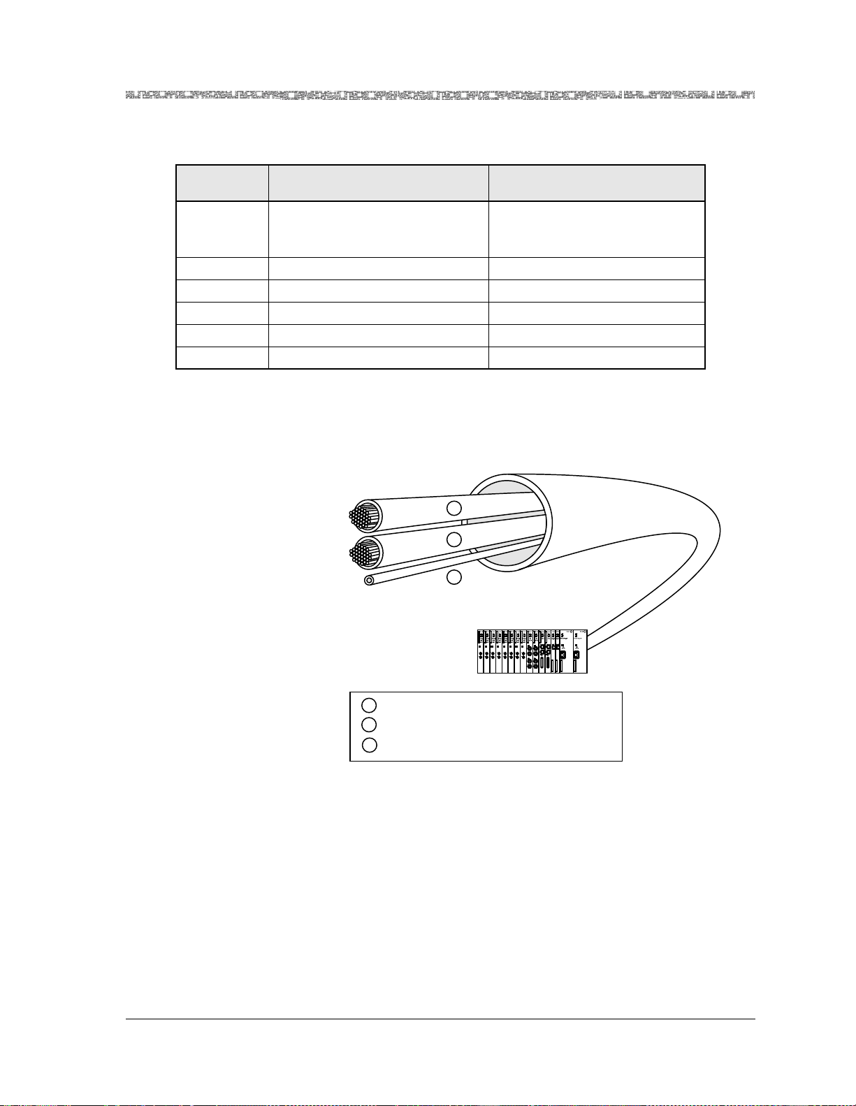
Chapter 3 System Features
Connections Support
Table 3-1. Sample User-Defined Priority Scheme for Reconnecti ng SPVC ATM IMA Links
User-Assigned
Priority Code
1 TDMA/CDMA control channels
AMPS channel reserved for 911
Traffic Type Typical ATM Service Type
CBR-1 or VBR-express
CBR-2
emergency calls
2 GSM control channels VBR-express
3 Digital voice channels VBR-express
4 GSM voice channels CBR-2
5 Most analog voice channels VBR-rt2 (will now try CBR-3)
6 Management data connections UBR
The SPVC Priority Reconnection feature supports all SPVC connection types.
All SPVCs compress voice when configured with the appropriate DSP2x Voice
Server module. SPVC connections are rerouted in the event of link failure.
Figure 3-1 shows some sample user-assigned priority SPVCs.
AAL2
CIDs
(max. 247)
AAL2
CIDs
(max. 247)
A
B
C
DS1/T1 IMA Link
PSAX System
Sample Priority 1,
A
Sample Priority 2,
B
Sample Priority 0,
C
AAL2 Trunk for HDLC SPVC
AAL2 Trunk for CE SPVC
PVC
Figure 3-1. Sample SPVC Reconnection Prioritization Scheme
The priority reconnection scheme is invoked by one of the following events:
• Chassis reboot
• IMA link failure followed by SPVC reconnection attempts
Upon IMA link failure, all SVC and SPVC calls are disconnected. SPVC calls
are then reconnected according to the priority scheme designated by the
user.
A PSAX system using the user-defined reconnection priority scheme must
meet the following requirements:
• Only active-side SPVCs are permitted in the configuration (no SVCs)
PacketStar® PSAX 1250 Multiservice Media Gateway User Guide, Issue 2 Release 8.0.0
255-700-247 3-5
Page 68

Chapter 3 System Features
Connections Support
• The maximum total number of AAL2 SPVC trunk connections in the chas sis must not exceed 32.
• The ATM uplink must be a 6-Port DS1 IMA module.
• The PSAX with the priority system enabled will work with a PSAX with
passive side SPVCs that has the priority system disabled.
Note: No preemption of existing connections is supported. Any existing
SVC, PVC, and SPVC connections will not be disconnected to
secure bandwidth for new connections.
Switched Virtual Circuit (SVC) Connections
Switched virtual circuit (SVC) connections are used for voice traffic over a
public ATM W AN or private line network. SVCs are supported on all the ATM
cell-bearing interfaces, including the DS3, E3, OC-3c, STM-1, Multi-Serial,
and High Speed modules. The Multiservice Media Gateway system software
supports the following features:
• Each ATM port on a single module ca n be indivi dually configured f or ATM
UNI 3.0, UNI 3.1, IISP user, IISP network, or PNNI interfaces.
• SVCs can be allocated on UNI (public and private), IISP, and PNNI interfaces.
• Point-to-point and point-to-multipoint VCC connections are supported.
• VCC connections support both symmetric and asymmetric bandwidth
requirements.
• An Multiservice Media Gateway system can process 60 calls per second.
Maximum limits include 100 UNIs per system; 5,000 simultaneous pointto-point SVC call originations, and 2,000 point-to-multipoint call originations.
• An Multiservice Media Gateway system (equipped with 64 MB of memory
on the CPU module) can process a maximum of 20,000 simultaneous SVC
calls in progress.
• The maximum individual call setup time is 16 milliseconds (ms). The minimum call setup time for SVCs is approximately 10 ms from the time the
call setup message enters the CPU module until the acknowledgment
leaves the CPU module.
PacketStar® PSAX 1250 Multiservice Media Gateway User Guide, Issue 2 Release 8.0.0
3-6 255-700-247
Page 69

Chapter 3 System Features
Connections Support
SVC Functional Description
SVC signaling, per ATM Forum UNI 3.0 and UNI 3.1, is selectable on a perport basis. Call control is performed on the CPU module, including management of the call-state transitions for each of the calls. This process allows ondemand allocation of bandwidth and connection resources. The signaling
protocol supports the following basic functions at the UNI interface:
Feature Description
Connection/Call Setup With this feature, calls originate and are
established.
Connection/Call Request With this feature, requests of resources for
connections to a certain destination are fulfilled. The Information Element (IE) field
contains resource information including
PCR, SCR, MBS, and QoS class.
Connection/Call Answer Wi th th is feat ure , the des tina tion p arty can
respond to a request with VPI/VCI and
other information related to the connection/call.
Connection/Call Clearing With this feature, the information associ-
ated with removing the call/connection
request is provided. This includes: 1) calls
removed because there weren’t enough
resources to meet the call request,
2) connections removed when call disconnect requests were received from either
party, and 3) calls removed due to link failure and other network failures.
Reason for Clearing With this feature, the clearing party can
indicate the cause for initiating its removal
from a connection/call.
Call States Call states exist o n both the user si de and the networ k side of the tr ansaction.
Call states define which messages can be accepted by the user or the ne twork
entity, and define how they are expected to react to those messages. As the
user or network entity moves from call state to call state, the call switching
process is accomplished.
In cases where the calling party is the user, and the called party is across the
network, the user-side interface (UNI) at the Multiservice Media Gateway
port presents a UNI to the user. The Multiservice Media Gateway port
receives these user-side messages from the user and—based on resource
availability, route determination, and other network factors—presents a network-side interface (NNI or IISP) to the called party or the network-side
Multiservice Media Gateway port.
PacketStar® PSAX 1250 Multiservice Media Gateway User Guide, Issue 2 Release 8.0.0
255-700-247 3-7
Page 70

Chapter 3 System Features
Connections Support
Both user-side and network-side interfaces undergo similar state transitions.
Transition messages trigger these call-state changes as follows:
#0—Null No call exists.
#1—Call initiated • User—The user has requested that the system
Call States Description
establish an outgoing call on the network.
• Network—The network has received the call
establishment request, but has not yet responded
to the outgoing call.
#3—Outgoing call
proceeding
• User—The user has received an acknowledgment
that all call information required for the outgoing
call to be established has been received from the
network.
• Network—The network has sent an acknowledg-
ment to the user that all call information has been
received.
#6—Call present • User—For incoming calls, the user has received
the call establishment request, but has not
responded yet.
• Network—For incoming calls, the user has sent
the call establishment request, but has not
received a satisfactory response.
#8—Connect request • User—For incoming calls, when the user has
answered the call and i s waiting to be a warded the
call.
• Network—For incoming calls, when the network
has received an answer but the network has not
yet awarded the call.
#9—Incoming call
proceeding
• User—For incoming calls, when the user has sent
acknowledgment that the user has received all call
information necessary to establish a call.
• Network—For incoming calls, when the network
has received acknowledgment that the user has
received all call information necessary to affect call
establishment.
PacketStar® PSAX 1250 Multiservice Media Gateway User Guide, Issue 2 Release 8.0.0
3-8 255-700-247
Page 71

Chapter 3 System Features
Connections Support
Call States Description
#10—Active • User—For incoming calls, when the user has been
awarded the call. For outgoing calls, when the
user has received an indication that the remote
user has answered the call.
• Network—For incoming calls, when the network
has awarded the call to the called user. For outgoing calls, when the network shows that the remote
user has answered the call.
#11—Release
request
• User—The user has requested that the network
clear the end-to-end connection and is waiting for
a response.
• Network—The network has requested a request
from the user to clear the end-to-end connection.
#12—Release indication
• User—The user has received an indication to dis-
connect because the netwo rk has disconne cted the
end-to-end connection.
• Network—The network has disconnected the end-
to-end connection and has sent an indication to
disconnect the user-to-network connection.
The following state transition messages are used for ATM point-to-point call
and connection control:
Call establishment messages:
• Call pro cee ding
• Connect
• Connect acknowledgment
• Setup
Call clearing messages: • Release
• Release complete
Miscellaneous messages: • Status
• Status inquiry
• The information elements used in the Call Establishment-Setup message
allow the user to request the called party number, specific PCR, SCR, MBS,
QoS class, forward and backward direction rates, performance, congestion
control parameters, and so on, from the Multiservice Media Gateway UNI.
The Call Establishment-Connect message allows the called party to respond
with available traffic parameters, such as PCR, SCR, MBS, QoS class, forward and backward direction rates, performance, congestion control
parameters, and so on. Usually this message also indicates the available
VPI/VCI allocated for the connection. The other state-transition messages
are specified by the ATM Forum UNI 3.0 and UNI 3.1 specifications and are
transparent to the user.
PacketStar® PSAX 1250 Multiservice Media Gateway User Guide, Issue 2 Release 8.0.0
255-700-247 3-9
Page 72

Chapter 3 System Features
User Interfaces
User Interfaces
The PSAX 1250 offers a variety of user interfaces to support voice, video, and
data applications.
Circuit Emulation Service
Circuit emulation service transports traffic over a virtual channel-based connection, providing service to the end user that is indistinguishable from a real
point-to-point, fixed-bandwith circuit. The PacketStar PSAX Multiservice
Media Gateways support structured circuit emulat ion (i ndividual DS0 circuit
emulation) of traditional voice-based and data services on the DS1 and E1
modules. Because voice services are essentially constant bit rate (CBR) data,
ATM Forum ATM Adaptation Layer 1 (AAL1) standards are used in circuit
emulation. The circuit emulation service also provides signaling bit transport
based on ATM Forum standards for c hannel-associated signaling (CAS).
The PacketStar Multiservice Media Gateways provide AAL1 circuit emulation
at the DS0 level. The individual DS0 modes of structured circuit emulation
allow service providers to switch time-division multiplexing (TDM) traffic
across the ATM network at individual subscriber levels; that is, each DS0 can
be assigned a separate virtual path identifier (VPI) or virtual channel identifier (VCI). This service transports ABCD signaling bits based on the ATM
Forum standard for G.704 CAS. M13 multiplexing capabilities are also supported, providing the ability to perform circuit emulation on a T1 or E1 link
connected to a TDM network and convert it into ATM cells, in accordance
with the ATM Forum CAS specification af-saa-0032.000. Each T1 or E1 carries all
of the Extended Super Frame (ESF) information required for a full T1 or E1
in cases where the interfaces to the service access multiplexer (SAM) are a
full T1 or E1. The Multiservice Media Gateways can convert superframe (SF)
format to ESF format. Signaling from any input interface (including customer
premises equipment [CPE] interfaces) is converted to the appropriate signaling on the output interface. Framing information is converted and assignments are made on an individual DS0 basis.
Voice frames are converted into ATM cells based on the ATM Forum Circuit
Emulation Service Interoperability S pe ci fication Version 2.0, af-vtm-0078.00. The
DS0 mode of structured circuit emulation transparently supports voice applications in a network environment.
SPVC Support for CES Also offered are DSP2C through DSP2F Voice Server processing options
(including voice compression, silence detection, echo cancellation, tone
detection, and PCM coding translation) for voice traffic on soft permanent
virtual circuit (SPVC) connections between two or more PacketStar PSAX
systems.
Circuit Emulation Service for the Multiserial Module
PacketStar® PSAX 1250 Multiservice Media Gateway User Guide, Issue 2 Release 8.0.0
3-10 255-700-247
Circuit emulation to ATM connections made through the Multi-Serial module now support 56 Kbps to 64 Kbps bit stuffing for SS7 link transport applications. Bit stuffing is selectable on a port basis by using the CPU software.
Page 73

Dynamic Bandwidth Circuit Emulation Service
The dynamic bandwidth circuit emulation service (DBCES) feature is used
with voice PVC connections to best utilize the available network bandwidth.
This feature allows channels to be allocated dynamically as needed, based on
ABCD signaling-bit information. The firmware supports 1x56 Kbps time-slot
trunking with channel-associated signaling (CAS) detection used, based on
ATM Forum Specification af-vtoa-0085.000. Note that this feature is not fully
compliant with the specificat ion and does not interopera te with other devices
that are fully compliant.
The DBCES feature, in essence, performs idle channel suppression for voice
traffic. PBX voice traffic uses DBCES to save some of the available T1 WAN
bandwidth for LAN traffic. On average, only 8 DS0s are used for voice traffic,
but at peak times, the number of DS0s used might approach the full 24 T1
channels. When channels are not being used for voice traffic, the available
bandwidth can be used for LAN UBR-class traffic.
Dynamic CAC
Connection Admission Control (CAC) is used to determine if a connection
set-up request can be supported by available resources. When a PSAX system
initializes, the CAC algorithm determines, in a static sense, the maximum
available bandwidth for each interface. As connections are created and
deleted, CAC keeps a running tally on available bandwidth so that it can
determine if new connections can be supported.
Chapter 3 System Features
User Interfaces
DS1 Service
DS3 Service
In general, since the maximum available bandwidth of an interface is fixed
(that is, DS1=1.536 Mbps), a static approach is usually sufficient. However,
there are exceptions. Dynamic CAC Phase 1 supports the potentially changing nature of inverse multiplexing for ATM (IMA) groups and accounts for
increases or decreases in the maximum available bandwidth of the interface
due to additions or deletions of component links. Phase 2 permits a user to
change DS3 ATM payload mapping from PLCP to direct mapping (which also
alters the maximum available band width) without ta king the interface o ut of
service or deleting existing connections.
With the channelized DS1 interface, service providers can concentrate and
adapt voice, video, and data traffic to an ATM network. The DS1 interface
can adapt any number of DS0 channels on the service access interface to
ATM virtual channels with individual virtual path identifiers (VPIs) and virtual channel identifiers (VCIs). Users can thus adapt traffic to ATM at the
individual DS0 level; that is, using structured circuit emulation, frame relay,
HDLC, and native ATM services. The PSAX 1250 system also offers unstructured circuit emulation on the service interface of the DS1 interface.
PacketStar® PSAX 1250 Multiservice Media Gateway User Guide, Issue 2 Release 8.0.0
255-700-247 3-11
Page 74

Chapter 3 System Features
User Interfaces
With the PSAX 1250 system, service providers can also now concentrate the
various ATM circuits onto an upstream interface to an ATM edge switch, typically at the DS3 rate. With the DS3 interface, service providers can concentrate various traffic types up to 45 Mbps. The DS3 ATM module, designed to
meet the ATM Forum UNI 3.0 specifications, serves as an interface to the service provider’s ATM edge switch. Each DS3 ATM module supports two 45Mbps DS3 ports.
HDLC Passthrough Bit Inversion
High-level data link control (HDLC) uses an ITU-TSS link layer protocol standard for point-to-point and point-to-multipoint communication. To reduce
errors, control information is always placed in the same position, and the bit
pattern is different from the data bit pattern. Providers are using this option
primarily in wireless TDMA applications with ATM, finding that it is possible
to save money by using ATM for backhauling calls from wireless cell sites to
mobile switching centers, instead of using time division multiplexing (TDM).
The process uses the new 5ESS switches that support a mixture of inverted
and standard HDLC passthrough interfaces. The HDLC Passthrough Bit Inversion option is enabled by a nondefault driver file to support the bit-inverted
mode.
Inversion will work for HDLC passthrough links at both 56 Kbps and
64 Kbps. Currently, bit inversion is available only with the Enhanced DS1
and STS-1e modules, by selecting a nondefault driver file.
Interim Interswitch Signaling Protocol (IISP) Interface
Interim Interswitch Signal ing Protocol (IISP) was formerly known as PNNI
Phase 0. Building on the ATM UNI 3.0/3.1 standard, IISP uses static routing
tables established by the network administrator to route connections aro und
link failures. IISP is meant to be used pending completion of the PNNI
Phase 1.
Private Network-Network Interface (PNNI) 1.0
Overview
The private network-to-network interface, known as PNNI, is a link state
protocol. This protocol enables extremely scalable, full function, dynamic
multivendor ATM switches to be integrated in a network. PNNI protocol
computes paths through a network by defining a method for distributing
topology information between switches and clusters of switches. This information is used to compute paths through the network, whether it is local or
worldwide. The hierarchy mechanism of PNNI ensures that this protocol
scales well for any size ATM network, and automatically configures itself in
networks in which the address structure reflects the topology.
PacketStar® PSAX 1250 Multiservice Media Gateway User Guide, Issue 2 Release 8.0.0
3-12 255-700-247
Page 75

PNNI Features Supported by the PSAX Systems
Chapter 3 System Features
User Interfaces
PNNI provides a method for signaling used to establish point-to-point and
point-to-multipoint connections across ATM networks. PNNI is based on the
ATM Forum UNI signaling, with mechanisms added to support source routing, crankback and alternate routing of all call setup requests in case of connection setup failure.
The path selections for specific calls are based on route options provided by
PNNI messages. Load sharing between parallel paths is addressed by the
route determination algorithm, which provides options for such factors as
load sharing, cost, and override options.
Phase 3 of the Private Network-Network Interface feature enhancement
includes the additions of functionality from the ATM Forum PNNI standard
af-pnni-00 55.000 Annex F, Hierarchy Configuration, and Appendix G, Minimum
Subsets (all border node capable switching systems fea tures). Ten hierarchal
levels are supported.
The following is a list of PNNI features supported for the PSAX systems:
• Alternate routing as a result of crankback
Blocked calls will be cranked back with an indication of the cause. Alter-
nate routes will be cons istent with the high er -level desig nated transit l ists
in the original call request, and will avoid the blocked part of the network.
• CBR, rt-VBR, nrt-VBR, and UBR service
• Hello protocol
• Peer group leader election algorithm
• Point-to-point SVC and SPVC connections
• Point-to-multipoint SVC and SPVC connections
• Transfer of incoming extended Quality of Service (QoS)
• End-to-end transit delay parameters to outgoing PNNI interfaces
• Single peer group hierarchy
• Topology database synchronization
• PNNI topology state element (PTSE) aging within topology databases
• Summation and advertising of reachable addresses
• Source path selection and generic connection admission control (GCAC)
PNNI Peer Group Dynamics
PNNI performs these functions:
• Simplifies the configuration of large networks because it allows ATM
switches to automatically learn about their neighbors and to distribute call
routing information dynamically.
• Allows switches to be arranged in a hierarchy, where each level represents
one or more switches. A cluster of switches at the same level is called a
peer group. Link-state topology updates circulate within a peer group.
• Allows up to 10 levels in a hierarchy but does not require them. It is also
possible to deploy PNNI with one peer group encompassing all switches
within a network.
PacketStar® PSAX 1250 Multiservice Media Gateway User Guide, Issue 2 Release 8.0.0
255-700-247 3-13
Page 76

Chapter 3 System Features
User Interfaces
• Sends hello packets across interswitch network-to-network interface (NNI)
links that enable switches in the same peer group to discover one another.
After a switch confirms that its neighbor at the other end of a link is a
member of the same peer group, both exchange PNNI topology state packets (PTSPs) to advise and update their call routing information. PTSPs carry
one or more PTSEs, describing the resources of the originating switch and
the outbound resources of each of that switch’s attached links.
PTSEs describe attributes, such as:
~ Traffic types each link can support (any of the various ATM QoS levels)
~ Maximum cell rate the link can sustain; cell delay variation (only for
~ Cell-loss ratio or cell-loss margin (CLM), a measure of the difference
~ Administrative weight (AW), a parameter that allows network architects
Switches make use of this resource information to assess which of the available paths will best ensure QoS parameters are met.
constant bit rate (CBR) and variable bit rate real-time circuits (VBRrt)
between effective bandwidth allocation and sustainable cell rate
to indicate relative link preference when deciding between alternative
routes
PNNI Topology State Element (PTSE) Information
PNNI Hierarchies
After the initial exchange of topology information among switches in a peer
group, regular broadcast topology updates are unnecessary. Each PTSE has a
finite lifetime. Since i ndividual elements age d ifferentl y, their refresh updates
occur at different times. This reduces the overhead associated with keeping
the topology of the group updated. The only time a PTSE is rebroadcast is
when there is a significant change in any of the key topology elements. For
example, any change in cell-delay performance on a link will trigger a PTSE
update from attached switches. Triggered updates further reduce network
overhead.
Every switch in a peer group is aware of the topology state of the entire
group. Thus it can build the entire call setup route from source to destination.
A topology showing three hierarchal node levels (grandparent, parent, and
child peer groups), peer group leader nodes, and peer group member nodes is
shown in Figure 3-2. Each node, at any level, has its address and rank on the
network described on the PNNI Node Configuration window.
As peer groups grow and incorporate more nodes, the state information in
each switch increases. PNNI supports hierarchies, which collapse the amount
of state information shared by all switches. (See Figure 3-2 for a topology
showing three hierarchal node levels (grandparent, parent, and child peer
groups), peer group leader nodes, and peer group member nodes.)
In networks that use a PNNI hierarchy, the switches at each level elect one
switch as a peer group leader (PGL). This PGL concurrently belongs to its
own level and to the next highest level, where it acts as a logical group no de
(LGN) that represents and summarizes topology information needed to reach
any of the lower-level switches. The higher-level peer group can mirror this
PacketStar® PSAX 1250 Multiservice Media Gateway User Guide, Issue 2 Release 8.0.0
3-14 255-700-247
Page 77

Chapter 3 System Features
User Interfaces
dual constituency, electing a PGL to represent it at the next highest level, up
to a maximum of 10 levels, in accordance with ATM Forum PNNI standard
af-pnni-00 55.000 Annex F, Hierarchy Configuration, and Appendix G, Minimum
Subsets (all border node capable switching systems feat ures). In addition,
PNNI does priority re-routing after RESET is done, or a lost link has occurred.
Each switch in a PNNI network has a unique 20-byte address that corre-
sponds to the network service access point (NSAP) schema. Much like IP subnet addresses, NSAP identifiers have a network part and a user part. The user
part is the last seven bytes, and is reserved for end-system identification
(insignificant to the PNNI). The network part is the first 13 bytes, and is used
to identify peer groups.
Each level in the PNNI hierarchy is also assigned a scope number. Similar to
an IP subnet mask, the scope specifies how much of the 13-byte network part
is common to the switch addresses at a particular level in the hierarchy. For
example, a scope of 72 (bits) masks the first 9 bytes of the network part as
being common in all switches at that level. Higher levels have shorter scopes
because they do not look as far into the NSAP; a level with a scope of 64
(masking the first 8 bytes) resides above a level with a scope of 72.
T o make the best use of PNNI’s capabilities, network architects must pay careful attention to the ATM addressing structure, allocating correct addresses to
switches at each level of the hierarchy.
PacketStar® PSAX 1250 Multiservice Media Gateway User Guide, Issue 2 Release 8.0.0
255-700-247 3-15
Page 78
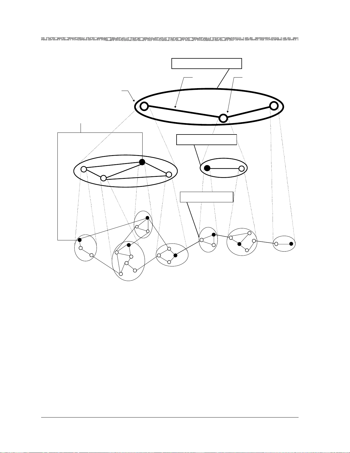
Chapter 3 System Features
User Interfaces
Grandparent Peer Group
Peer Group Leaders
A.1
PG(A.1)
A.1.3
A.1.2
A.1.1
Highest Level
Peer Group
A.4
PG(A.4)
PG
A.4.2
A.4.3
(A)
A.2
A.4.5
PG(A.2)
A.4.1
A.4.4
A.4.6
A.2.3
A.2.2
A.2.1
Logical Link
A
Logical Group Node
C
B
Parent Peer Group
PG (B)
A.3
PG(A.3)
A.3.4
Child Peer Groups
PG(B.1)
A.3.1
A.3.2
A.3.3
B.1.3
B.1
B.1.1
B.1.2
B.2
PG(B.2)
B.2.2
B.2.3
B.2.1
B.2.4
B.2.5
PG(C)
C.2
C.1
[ Source: Private Network-Network Interface (PNNI 1.0) Specification Version 1.0, af-pnni-0055.000 ]
Figure 3-2. PNNI Hierarchical Topology Showing Three Node Levels
ATM Maintenance
ATM Maintenance Mode is a way of rerouting SPVCs and SVCs from an ATM
port running PNNI. When a PNNI interface’s administrative weight is
changed, traffic on existing connections (PVC, SVC, SPVC) will not be disturbed. New SVCs and SPVCs are routed away from a PNNI link that has
high administrative weight.
ATM Maintenance Mode supports the following:
• PNNI interface on all ATM ports.
• PNNI administrative weights are configured at the PNNI interface level.
The administrative weight can be changed without taking the interface
down or disturbing existing traffic on that ATM port.
PacketStar® PSAX 1250 Multiservice Media Gateway User Guide, Issue 2 Release 8.0.0
3-16 255-700-247
Page 79

• The new administrative weight will be communicated to the ATM switch
on the other end of the PNNI link via PNNI link messages.
• Both SVCs and SPVCs from far end and near end ATM switch [n1]are
routed away from the PNNI link with high administrative weight.
• This procedure interoperates with Marconi/Fore and GX 550 ATM
switches.
Integrated Link Management Interface (ILMI)
The integrated link management interface (ILMI) is a network management
function that supports bidirectional exchange of ATM interface parameters
between two connected ATM Interface Management Entities (IMEs). These
entities are an end user and a public or private network, or a public network
and a private network.
Based on an ATM Forum-defined interim specification, ILMI uses a limited
subset of Simple Network Management Protocol (SNMP) capabilities. ILMI
provides status information and statistics using SNMP and a MIB to provide
any ATM device with status and configuration information about the following information available at its ATM interfaces:
• Virtual path connections (VPCs)
• Virtual channel connections (VCCs)
• Registered ATM network prefixes
• Registered ATM addresses
• Registered service s and capabilit ies
Chapter 3 System Features
User Interfaces
ILMI over PNNI Overview
With System Software Release 6.5.0, VPI and VCI range negotiation is supported. It also determines the operational status of the logical port. ILMI is
supported for all ATM UNI 3.0 and ATM UNI 3.1 interfaces.
The ILMI over PNNI feature supports VPI and VCI range negotiation using
automatic configuration procedures.
The automatic configuration procedure is the ability to automatically configure the following fields, found on the ATM PNNI Interface Configuration
window, based on the local VPI/VCI and the remote VPI/VCI ranges (VPI and
VCI range negotiation):
• Min/Max SV C VPI
• Min/Max SV C VCI
The PNNI ILMI Configuration window and PNNI ILMI Statistics window can
be accessed from the ATM PNNI Interface Configuration window. The PNNI
ILMI Configuration window is very similar to the ATM UNI ILMI Configuration window.
For more information on automatic configuration procedures, see ATM
Forum ILMI (Integrated Local Management Interface), 4.0, a f-i lm i-0065.000, Section
8.3.4.
PacketStar® PSAX 1250 Multiservice Media Gateway User Guide, Issue 2 Release 8.0.0
255-700-247 3-17
Page 80

Chapter 3 System Features
User Interfaces
Load Balancing for IISP and PNNI
Load balancing allows communications trunks connecting access and edge
switches to balance traffic between PNNI (dynamic source routing) and IISP
(static hop-by-hop routing) links. In addition to the existing parameters of
path and route selection, the PSAX devices consider the values of available
bandwidth and available cell rate associated with the interfaces. The PSAX
calculates routes b y u sin g av ai labl e ban dwidt h wi thin t he de faul t par ame ter s
for both IISP and PNNI r out ing. Load bala nci ng bet ween P NN I and IIS P li nks
uses available bandwidth more efficiently while strengthening the routing
function.
ATM Terminal Emulation
Terminal Emulation is an application that follows an intelligent computing
device to mimic the operation of a dumb terminal for communications with a
mainframe or minicomputer. This is made possible by inserting special
printed circuit boards into the motherboard of the emulating device, and/or
special software. The 6-Port Multiserial module is the only Multiservice
Media Gateway module that supports this interface.
UNI 4.0 Signaling
The UNI 4.0 Signaling feature supports the mandatory functions required by
the ATM Forum UNI Signaling Specification Version 4.0, as well as some of
its optional features. UNI 4.0 provides the signaling procedures for dynamically establishing, maintaining, and clearing ATM connections at the ATM
user-network interface. UNI 4.0 applies both to public and private UNI interfaces.
Major highlights of UNI 4.0 include:
1. Individual QoS parameters
2. Elements to support narrowband ISDN over ATM
3. Procedures,connection scope selection information element, and new
MIB object to support the ATM AnyCast capability.
4. Procedures and new information elements to support bandwidth modification
5. New virtual path indicator (VPI)/virtual channel indicator (VCI) options
6. Procedures to support multiple virtual UNIs on a physical UNI
7. Error handling for instruction ind icators
8. Using setup for adding part ies
Inverse Multiplexing for ATM (IMA)
PacketStar® PSAX 1250 Multiservice Media Gateway User Guide, Issue 2 Release 8.0.0
3-18 255-700-247
Page 81

Inverse multiplexing for ATM (IMA) creates virtual access pipes that are
faster than an E1 line, but not nearly as expensive as a T3/E3 line. This
allows customers to gain ATM capabilities without the costs associated with
broadband access. The 6-Port DS1 IMA, 12-Port Medium-Density DS1 IMA,
6-Port E1 IMA, 21-Port High-Density E1 IMA, and 1-Port DS3 IMA I/O
modules support the ATM IMA interface.
Automatic Use of IMA Links
In an IMA group, if one link is broken, the group can be configured to automatically use the other links. For example, if an IMA group has three DS1
links and one of the links fails, although the throughput will drop from 4.5
Mbps to 3.0 Mbps, the IMA group continues to work. If the slowest link fails,
there will be some cell loss on CBR connections as the other links speed up
their cell rate to eliminate excess delay, due to their buffering of cells.
IMA Configuration Considerations
Note: If your PSAX device will be interoperating with a device that has
implemented ATM Forum IMA ATM Specification Version 1.0
such that its equipment incorrectly reports link states to the farend of an IMA connection, you must configure IMA groups with
the compatibility mode turned on. This also causes the PSAX unit to
correctly report link states and interoperate with your ATM
Forum IMA ATM Specification Version 1.0 equipment.
Chapter 3 System Features
User Interfaces
The following is a list of operations considerations for the IMA interface:
• Once an IMA group has been deleted, its status is displayed as "Insufficient-
Links."
• Links may not be added or removed from a group that is configured. You
must delete any existing interfaces applied to the group before adding or
removing links.
• Operational Status refers to IMA group status, which can be viewed in the
port and channel configuration window.
~ You can restart an IMA group by taking it administratively out of service
and then bringing it back into service.
~ In order to change any group configuration parameters, t he group must
be completely unconfigured.
~ There may be difficulties if the IMA group is configured for symetric
operation but has asymetric link delays. For example, one end may consider links A, B, and C to have problems, while the other end considers
D, E, and F to have problems.
~ Four configurable transmit frame lengths are provided: 32, 64, 128, 256
cells. One ICP (IMA communication protocol) cell is sent over each link
once per IMA frame. If you select a larger frame length, there will be less
overhead. If you select a smaller frame length, the IMA group has better
response in communications with the far end, resulting in faster error
detection and recovery. The IMA specification only requires equipment
to support a frame length of 128. If a frame length other than 128 is configured and the far-end is connected to equipment that doesn’t support
it, the far-end group enters the config-abort state.
PacketStar® PSAX 1250 Multiservice Media Gateway User Guide, Issue 2 Release 8.0.0
255-700-247 3-19
Page 82

Chapter 3 System Features
User Interfaces
~ The IMA identifier (ID) is an 8-bit (0-255) identifier for this IMA group.
There is no significance to any particular values of IMA IDs. Since the
IMA ID is used to identify a group to the far-end, pick a unique value
instead of leaving it as the default of 0.
Frame Relay-to-ATM Interworking
Frame relay-to-ATM interworking is performed at the network level, Frame
Relay Implementation Agreement FRF.5, and at the service level, FRF.8. This
allows a PacketStar Multiservice Media Gateway to adapt a nd concentrate
traffic from one frame relay network and transmit it to other frame relay or
ATM networks. In this way, the Multiservice Media Gateway acts as a gateway between routers, remote-dial access servers, systems network architecture (SNA) equipment, and other devices configured for frame relay operation.
FRF.5 Encapsulating Frames
FRF.8 Converting Frames
With FRF.5 network level i nterw orkin g, fra mes a re en capsul ated wi thi n ATM
cells at the network ingre ss p oint a nd "tu nneled" thr ough t he ATM network.
At the network egress point, the ATM cell headers are removed and the
frames are reassembled for delivery to a frame relay device.
With FRF.8 service level interworking, frames are converted into one or more
ATM cells at the network ingress point. At the network egress point, the ATM
cells are delivered to an ATM device. This conversion is compliant with both
the FRF.8 implementation agreement and the IEFT multiprotocol encapsulation specifications (RFC 1490, RFC 1483). FRF .8 interworking is performed at
the end of the ATM network that connects to the frame relay device.
Note: FRF.5 and FRF.8 are not interoperable and cannot be used at both
sides of a network. You may wish to use an FRF.8 approach for
applications involving interconnectivity between two frame relay
devices because the capabilities of FRF.8 include those that are
available with FRF.5.
Frame Relay-to-Frame Relay Interworking
In addition to frame relay-to-ATM interworking, it is possible to configure a
Multiservice Media Gateway for strictly frame relay operation. A frame relayto-frame relay connection can be made between two ports of a Multiservice
Media Gateway if both ports have frame relay capacity. In this case, frame
relay data received by one of the ports is converted to ATM cells for transmission across the backplane of the Multiservice Media Gateway, and then converted back into frame relay for transmission from another port.
GR-303 Interface
The Telcordia Technologies General Requirements 303 standard provides for
both an open interface networ k architect ure and a digi tal loop carrier sy stem
that operates o n T 1 ci rcu it s. This s tan da rd al lows a remo te ter min al such as a
central office PacketStar PSAX Multiservice Media Gateway to flawlessly
PacketStar® PSAX 1250 Multiservice Media Gateway User Guide, Issue 2 Release 8.0.0
3-20 255-700-247
Page 83

Chapter 3 System Features
User Interfaces
interface with a Lucent Stinger™ DSLAM, a CellPipe™ IAD or AdTran
TA624.850, and a central office voice switch, such as the Luce nt Technologies
5ESS switch, or with Nortel’s DMS switch.
Operating on T1 circuits, the GR-303 digital loop carrier service has provisions for both an open interface network architecture and a digital loop carrier system. The performance standards of the GR-303 interface are derived
from the high-level internetworking capabilities established in Telcordia
T echnologies General Requirements 303, and allow a central office PacketStar
PSAX Multiservice Media Gateway to interface with central office voice
switching equipment as a remote terminal.
The interface assigns and manages connections on a time slot management
channel (TMC) and supports operating functions on an embedded operations
channel (EOC), with each channel configured on I/O modules that support
the GR-303 interface protocol. The user guide details a configuration for one
GR-303 group using the ratio concentration of 2048 CRVs to 668 DS0s,
approximately a 3:1 oversubscription rate per DSP2C/D voice processing
chip. (A CRV is a call reference value that the 5ESS switch will map to a
phone number). The GR-303 specifications recommend connection concentrations from 1:1 up to 3:1, expandability from 2 to 28 DS1 circuits for each
GR-303 group, and expandability from 1 to 2,048 subscriber channels per
GR-303 interface group.
The oversubscription factor you can achieve depends on what modules configuration is chosen. You can decide what ratio to oversubscribe the DS0/CE
resource. Higher channel densities per DSP chip resource and more AAL2
trunking groups are achieved by upgrading to the DSP2D Voice Server module from the DSP2C.
The maximum number of GR-303 interface groups supported on the PSAX is
84. Loop emulation services provide multiplexed AAL2 PVC support for the
PacketStar PSAX Multiservice Media Gateway central office product line.
Loop emulation services allow voice traffic, DTMF, and signaling to be handled over the packet network. The circuits can interwork with time division
multiplexing (TDM), ATM digital subscriber line (DSL), or GR-303 interfaces.
The PSAX Multiservice Media Gateway also supports these features:
• Caller ID
• Call forwarding
• Call transfer
• Call waiting
• Cancel call waiting
• Customer callback
• Speed dialing
• Three-way calling
• Loop start line
• Visual and audio message waiting indicator
Because GR-303 software requires a large amount of random access memory
(RAM), which exceeds the capacity of the original CPU module, full implementation of all GR-303 features requires using a CPU2 module (model
PacketStar® PSAX 1250 Multiservice Media Gateway User Guide, Issue 2 Release 8.0.0
255-700-247 3-21
Page 84

Chapter 3 System Features
User Interfaces
20P25). The CPU2 module has double the RAM capacity as the original CPU
module. Users can enable or disable the GR-303 feature as needed. If this feature is not needed, disabling it allows the system to allocate more RAM for
other system functions.
Phase 3 certifies the DSP2D Voice Server Module for interoperability with the
Stinger DSLAM, the 5ESS CO switch, the CellPipe™ IAD, and the PSAX 2300
Multiservice Media Gateway supporting GR-303 Loop Emulation Services.
For information on configuring GR-303 with the DSP2C and DSP2D Voice
Server modules, refer to Configuring the CellPipe
PSAX Multiservice Media Gateway as Interworking Functions Using the GR-303
Standard Appli cation Note, Issue 2, Release 7.1.0, Document No. 255-700-135.
This document is available for the Lucent Customer Information Center at
http://www.lucentdocs.com.
In System Software Release 8.0.0, the following enhancements have been
added to the DSP2D Voice Server module for connections using the GR-303
protocol:
Fax/Modem Master/Slave Support
The PSAX system supports fax/modem tone detection for the ATM downlink
side at 32 Kbps using ATM Forum profiles.When the DSP2D is configured as
a CP-IWF with an IAD in the CO-IWF, the module performs automatic algorithm switching to match the algorithm used on incoming AAL2 data streams
from CO-IWF devices, such as the Lucent CellPipe and the Adtran
TA624.850. This results in voice compression and echo cancellation being
turned off for the duration of the fax call. A form of master/slave device hierarchy , the PSAX s ystem func tions as the mas ter device a nd the IAD functions
as the slave. This feature has been added to the firmware on the DSP2D module and is not configured by the user.
™
IAD, Stinger DSLAM, and
CAS Refresh Rates in the On-Hook State
Refresh rates are fixed in the firmware for 5 minutes in the on-hook state,
and 5 seconds in the off-hook state, using the AlgoSet6 voice processing feature set. If you prefer the NOC to be notified sooner in case of connection
failure, turn the call logging feature on in the Stinger DSLAM. The Stinger
notifies the NOC by means of a trap message as soon as a DSL connection
fails and the Stinger port receives a LOS indication. For guidance on Stinger
configuration, see the Stinger Administration Guide, Part Number: 7820-0712-
002, Software Version 9.0-139, January 2001, and the Stinger Reference Guide, Part
Number: 7820-0713-003, Software Version 9.0-139, March 2001 for details.
Idle Channel Suppression Support for the CellPipe IAD
The CellPipe IAD is certified to not transmit silence cells between itself and
the PSAX when in the on-hook state if a channel is idle (supporting no active
connection).
PacketStar® PSAX 1250 Multiservice Media Gateway User Guide, Issue 2 Release 8.0.0
3-22 255-700-247
Page 85

Network Management
The Multiservice Media Gateway system provides all the telecommunications
management network (TMN) functions applicable to the system. The
PSAX 1250 system (which contains network elements) can be managed in
several ways using a network element management system or network management system. The Multiser vice Medi a Gateway s ystem so ftware f eatures a
Simple Network Management Protocol (SNMP)-compliant management
information base (MIB) that gives external management systems access to
the Multiservice Media Gateway system software.
In conjunction with the visual indicators displayed on the front panels of the
individual modules, the system offers a full complement of SNMP trap messages that alert the user to fault s i n the P SAX 1250 system. Usage- bas ed m essages collected on the CPU module allow a service provider to collect cell
counts for traffic and performance monitoring, and for fault detection.
The SNMP MIB provides an extensive series of configuration management
and provisioning features that allow the user to prepare the various components for supporting servic es.
The Multiservice Media Gateway system software supports the following
options for network management:
• Serial port interface with a direct connection to a standard VT100 terminal
emulator.
As the simplest option, the CPU module faceplate provides an EIA-232
serial port (RJ-11 connector labeled CONSOLE), to which a PC workstation
or a console monitor, running a standard VT100 terminal emulator, is connected.
The console interface provides access to the configuration, fault, network
data-collection, and security-management features of the system software.
The Multiservice Media Gateway system software lets users perform management tasks using a me nu-based interface.
This port is typically used for local management (using a direct serial connection), but it can also be use d for remote management. Remote management may be performed over a public switched telephone network (PSTN)
with the use of an external modem, or over an ATM network with the use
of a terminal emulation connection from a Multi-Serial module. The serial
port is also used for the configuration of Internet Protocol (IP) parameters,
which are necessary for IP-based man a g eme n t .
• Ethernet interface connection on a local-area network (LAN).
A 10BaseT Ethernet interface (RJ-45 connector labeled ETHERNET) on the
PSAX 1000, PSAX 1250, PSAX 2300, and PSAX 4500 CPU module faceplates allow the user to access the MIB, either using the AQueView application over a LAN or by telneting to the PSAX system. If a telnet session is
used to manage a PSAX device, then the console interface is displayed
(similar to that which is used for the serial interface, as explained above).
Only one person can have access to the console interface at a time; therefore, direct access using the serial port precludes telnet access using the
Ethernet port.
Chapter 3 System Features
Network Management
PacketStar® PSAX 1250 Multiservice Media Gateway User Guide, Issue 2 Release 8.0.0
255-700-247 3-23
Page 86

Chapter 3 System Features
Network Management
• In-band management by using a PVC connection over an ATM wide-area
network (WAN).
The in-band management feature on the CPU module allows a user to
access and manage one or more PSAX systems (managed targets) via a single PVC connection from a management workstation (management host)
running an SNMP client over an ATM WAN. This allows for IP-based functions (that is, telnet) and SNMP functions (that is, element and network
management software) to be performed remotely using ATM virtual circuits, which terminate within the managed node. The PVC/SVC connection is set up using an I/O module with an ATM cell bearing port (for
example, the OC-3c, STM-1, DS1, DS3, E1, and E3 modules). Three basic
types of configuration are possible:
• Direct connection
• Routed connection
• Hybrid connection
For more information on these three basic connection types, see the
appendix, “Co nfiguring In-band Management.” For more information on
configuring in-band management SVC conne ctions, see Chapter 4, “Site-
Specific Configuration.” For more information on configuring in-band
management PVC connections, see the appropriate PacketStar PSAX Module
User Guide.
AQueView® Element Management System
The Navis™ AQueView® Element Management System (EMS) software is a
GUI-based element manageme nt tool that is used to provision the PacketStar
PSAX 1000, PSAX 1250, PSAX 2300, and PSAX 4500 Multiservice Media
Gateway systems. The AQueView EMS enables a network of PSAX devices to
be managed and provisioned from a single location, using easy-to-use windows. The AQueView
performance, and sec urit y man age m e nt of PSAX sy st em s.
Release 6.0 supports the same software features supported in the PSAX system software Releas es 8.0 .n, 7.1.n, and 7.0.n. The AQueV iew EMS is available
in two versions:
• Client/Server applica tion:
~ The Client and server can be installed on Sun Solaris platforms with or
without HP OpenView NNM
~ The Client alone can be installed on Sun Solaris platforms with HP Open-
View NNM
~ The Client alone can be installed on Windows NT, Windows 2000, and
Sun Solaris platforms without HP OpenView NNM
• Standalone application:
Can be installed on Windows NT, Windows 2000, and Sun Solaris platforms without HP OpenView NNM
EMS also provides centralized configuration, diagnostic,
®
For more information on AQueView R6.0 functionality, refer to the following
documents:
PacketStar® PSAX 1250 Multiservice Media Gateway User Guide, Issue 2 Release 8.0.0
3-24 255-700-247
Page 87

Chapter 3 System Features
Multiservice Media Gateway Software Features
• Navis™ AQueView® Element Management System User Guide for the Client/Server
Application
®
• Navis™ AQueView
Element Manageme nt System User Guide for Standalone Sys-
tems
Multiservice Media Gateway Software Features
Connection Gateway API
Connection Gateway API Overview
The Connection Gateway Application Programming Interface (CGAPI) provides a communications protocol or set of messages by which a call controller
can control ATM switching on a PSAX Multiservice Media Gateway system
®
using nonnative ATM networking protocols. See the PacketStar
Connection
Gateway Application Programming Interface Developer’s Guide for detailed infor-
mation about implementing a connection gateway API.
The Connection Gateway application programming interface (API) provides a
TM
robust interface with a goal of allowing the full line of PacketStar
PSAX
access concentrators to route non-ATM traffic, smoothly interworking with
nonnative ATM, ISDN, SS7, CAS, and other protocols.
For channel-associated signaling (CAS), the Connection Gateway API offers
both R1 and R2 support. The gateway supports switched voice traffic over
ATM by improving narrowband options through AAL1 and AAL2 trunking.
The gateway provides service level interworking, provisioning, fault monitoring, continuity service checking, and line testing support for the Channelized
DS3 module and/or the STS-1e T1 module. It extends continuity checks and
line tests to the I/O circuit emulation service (CES) modules. The capabilities
are particularly useful for offering voice traffic over ATM and for conveying
data.
The Connection Gateway API Enhancements, Phase 6, are as follows:
• A DSP2D interface failure indication message is sent when a call is set up
with echo cancellation enabled and the DSP2D chip used in this call has a
failure.
• DSP2 resource messages are used to obtain interface information on DSP2
modules in the system.
• The DSP2 call reroute feature automatically routes calls from DSP2D mod-
ules with failed chips to other configured chips on the same modules or to
any other DSP2 module in the system.
• When the PSAX Multiservice Media Gateway system is set up as the client
in a Site Specific Configuration, a Connection Gateway API interface
address is used as an interface on which to send Connection Gateway API
messages.
A developer’s guide explains the possibilities opened up by the Connection
Gateway API for a technical audience.
PacketStar® PSAX 1250 Multiservice Media Gateway User Guide, Issue 2 Release 8.0.0
255-700-247 3-25
Page 88
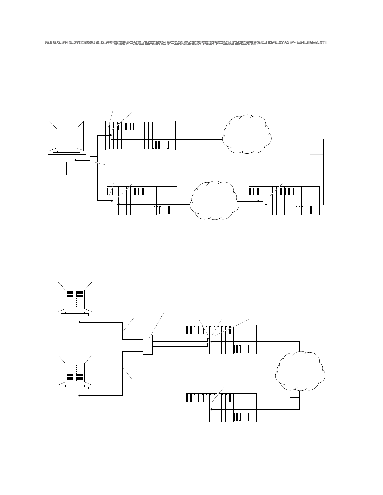
Chapter 3 System Features
Multiservice Media Gateway Software Features
The PSAX 1250 As a
TCP Client/Server for
the Connection
Gateway API
Call Controller
Device (Computer)
(TCP Server)
If you are using the Connection Gateway API with your PSAX system, you
need to configure the system as either a TCP client device or a TCP server
device. If you set up the PSAX system as a TCP client device, you can connect
multiple PSAX systems as TCP client devices to a call controller, which is set
up as a TCP server device (see Figure 3-3).
Ethernet
Module
ATM I/O
Module
ATM
WAN
Local Access Concentrator
(Primary TCP Client)
Ethernet Hub
Ethernet
Module
ATM I/O
Module
In-band
Management
PVC Connection
In-band
Management
PVC Connection
ATM I/O
Module
ATM
WAN
Local Access Concentrator
(Backup TCP Client)
Figure 3-3. PSAX System as a TCP Client Device
Remote Access Concentrator
(TCP Client)
Call Controller
Device-Primary (Computer)
(TCP Client)
Call Controller
Device-Backup (Computer)
(TCP Client)
You can also set up the PSAX system as a TCP server device with the call controller set up as the client device. As an option, you can connect two call controllers, set up as primary and backup client devices, to the PSAX system
(server device) (see Figu re 3-4).
Ethernet
Connection
Ethernet
Hub
Ethernet
Module
ATM I/O
Module
Local Access Concentrator
(TCP Server)
Route Server
Module
ATM
ATM I/O
Ethernet
Connection
Remote Access Concentrator
Module
(TCP Server)
Figure 3-4. PSAX System as a TCP Server Device
In-band
Management
Connection
WAN
PacketStar® PSAX 1250 Multiservice Media Gateway User Guide, Issue 2 Release 8.0.0
3-26 255-700-247
Page 89

DS1 ANI In-line Codes for Loopbacks
The Channelized DS3 Multiservice and CES modules support activating and
deactivating DS1 access network interface (ANI) in-line loopback codes
embedded in the DS1 signal. These codes test transmissions between customer interface equipment and network interface equipment, for example,
between PSAX central office (CO) products and customer premises equipment (CPE) products at the edge of an ATM network. The PSAX system also
generates alarm indication signals on all affected DS1 connections whenever
a loop is activated.
DS0A Non-Latched Loop Codes
In addition to the no loopback and the line loopback modes of operation
present in the 12-Port Medium-Density DS1/E1/DS0A module (DS0A mode)
in Release 7.1.3, three new, user-configurable, loopback modes have been
added in Release 8.0.0:
• Transmit mode
• Monitor mode
• Transmit and monitor mode
Chapter 3 System Features
Multiservice Media Gateway Software Features
In conjunction with these three modes, six fields can be configured:
• Transmit loop up code
• Transmit loop down code
• Receive loop up code
• Receive loop down code
• BERT pattern
• Timeout (Transmit loop code duration)
In Transmit mode, the module outputs 1 second of transmit loop up code followed by 1 second of BERT pattern on the line, repeating this pattern until
Timeout is reached, at which point 1 second of transmit loop down code is
sent on the line. The module is also in remote loopback in this mode. The
purpose of this mode is to test the operation of the module connected on the
far end of the line when it det ects and retur ns the loopcod es transmitte d. The
DS0A module reports to the CPU2 module whether the transmit loop up
code or transmit loop down code was received.
Monitor mode is the opposite of transmit mode. Here, the module on the far
end must verify that the near-end DS0A module is working properly by
sending loop codes on the line. In monitor mode, the DS0A module operates
normally—that is, passes real traffic—until it receives the receive loop up
code on the line. At that point, the module is set to line loopback and remote
loopback and reports to the CPU2 module that it had a matching of the
receive loop up code. When the DS0A module detects the receive loop down
code, it is taken out of loopback and reports the receive loop down code
matching to the CPU2 module. If the module is in loopback mode and does
not detect either of the receive loop codes, it automa tically re turns to no rmal
mode after two minutes.
PacketStar® PSAX 1250 Multiservice Media Gateway User Guide, Issue 2 Release 8.0.0
255-700-247 3-27
Page 90

Chapter 3 System Features
Multiservice Media Gateway Software Features
Tran smit and monito r mode is exac tly the s ame as tr ansmit mo de exce pt that
the DS0A module also rep ort s to the CPU2 modu le a matching o f the recei ve
loop up and loop down codes.
PSAX 1250 System Traffic Protection Capabilities
APS/MSP Protection on the Optical Modules
Interface Protection Group Feature
The 1+1 Automatic Protection Switching (APS)/Multiplex Section Protection
(MSP) feature provides connection redundancy for traffic flow protection on
the PSAX optical I/O modules. These modules, which can be used in any
PSAX Multiservice Media Gateway chassis, include:
• 1-Port OC-3c 1+1 APS Multimode and Single-Mode modules
• 1-Port STM-1 1+1 MSP Multimode and Single-Mode modules
• 1-Port OC-12c/STM-4c Multimode and Single-Mode modules
These modules are used in pairs, installed in adjacent slots in the PSAX chassis. In the event that the active module in the pair fails, the traffic is switched
to the standby module. The 1+1 protection implementation is compliant with
the GR-253-CORE standard and supports linear nonrevertive 1+1 protection,
in both bidirectional and unidirectional modes. Nonrevertive means that
connections that were switched from the active module to the standby module are not automatically switched back to the active module after a failed
link becomes operatio nal again. One advantage of nonrevertive switching is
minimal service interruption—one interruption instead of two.
The Interface Protection Group feature provides the capability to configure
interface protection groups of ATM interfaces that support PVC connections
on PSAX modules. Interface protection groups can be configured as primary
(active) and secondary (standby). Similar types of interfaces must be must be
grouped together in the same group. For example, in a primary (active)
group, you could set up this group with all DS3 ATM UNI 3.0 having the
same parameters, and in the secondary ( standby) group, yo u could set up the
same type of interfaces having the same parame ter s as in the pri mary grou p.
Specifically, this feature allows a user to group similar types of interfaces
together by specifying which interfaces in the group are primary (normally
carrying traffic) or standby (normally idle). The feature permits N:1 and 1:1
schemes by allowing several primary interfaces and one standby interface to
exist with a user-defined interface protection group.
When a failure condition is detected on a primary interface, the feature
moves all affected connections from the primary interface to a standby interface. The standby interface is selected from those available in the interface
protection group based on criteria selected by the user.
To use this feature, the following sequence of configuration tasks must be
performed:
1. Configuring the ports,channels, and interfaces on the modules (physical
layer interface)
2. Configuring connections (ATM layer and IWF)
3. Configuring the inteface protection groups
PacketStar® PSAX 1250 Multiservice Media Gateway User Guide, Issue 2 Release 8.0.0
3-28 255-700-247
Page 91
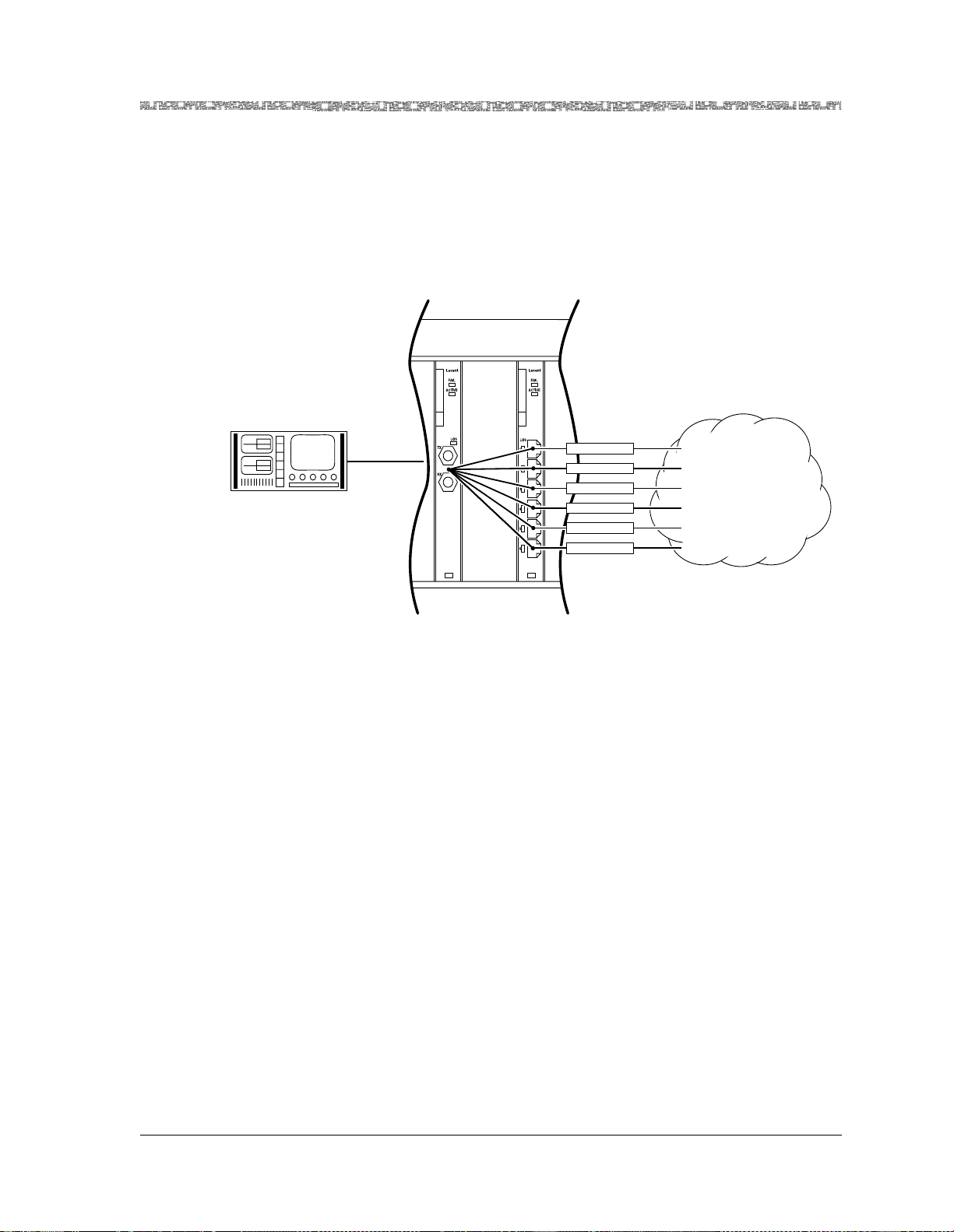
Chapter 3 System Features
Multiservice Media Gateway Software Features
Figure 3-5 illustrates how a typical interface protection group configuration
works. After the protection groups are created, they are displayed on the Protection Group Table and the Interface Protection Table windows on the console interface. When a switchover is initiated by the primary interface, the
IWF for that interface is torn down and replaced by the standby interface’s
IWF within that group. These configurations are displayed on the appropriate
PVC connection screen.
PSAX 2300
AX4000
Gen/Ana
IMA
DS1
DS3
IMA
Primary 1 Group 1
Primary 2 Group 1
Primary 3 Group 1
Primary 4 Group 1
Primary 5 Group 1
Primary 6 Group 1
ATM
Figure 3-5. Typical Interface Protection Group Configuration
This feature moves connections within a defined group whenever a failure
condition occurs or operator issues a switchover/switchback command.
• The switchover method is automatic, where traffic from a primary interface
is automatically switched to an available standby interface, and Manual,
where traffic from a failed primary interface is only switched to the available standby interface when the User selects the switchover.
• The switchback method is automatic, where traffic from a standby is
switched back to its corresponding recovered primary, and Manual, where
the standby interface does not switch the traffic back to the corresponding
primary interface until selected by the User.
Alternate Rerouting Using Dual-Homed PVCs
Overview of Dual-Homed PVCs
To protect ATM traffic from network power outages, the Multiservice Media
Gateway system can detect alarms or failures on an ATM backbone and
reroute PVC traffic around the affected portions of the network. Using dualhomed PVCs (DHPVCs), the system performs the rerouting function independently, without relying on operator intervention or rerouting capabilities
within the network itself.
This implementation allows for DHPVCs to be established for ATM-to-ATM
connections, circuit emulation-to-ATM connections, frame relay-to-ATM
connections, bridge-to-ATM connections, and terminal emulation-to-ATM
PacketStar® PSAX 1250 Multiservice Media Gateway User Guide, Issue 2 Release 8.0.0
255-700-247 3-29
Page 92

Chapter 3 System Features
Multiservice Media Gateway Software Features
connections. DHPVCs for virtual paths can only be implemented on ATM-toATM connections. Alternate rerouting is a standard feature of the system
software. The system sets up DHPVCs according to an industry-standard
technique.
It is not necessary to designate an interface to perform solely as the "standby"
for DHPVCs. Rather, ATM trunk interfaces can be used in a load-sharing
design with the connection admission control (CAC) constraints automatically considered as the DHPVC is established. This allows particular links to
be used as the primary link for certain DHPVCs while they are used simultaneously as the standby for other DHPVCs.
Operation
As the DHPVC is es tab lis hed, b ot h t he p r imar y a nd st and by circui t s are p r ov isioned from the originating node to the terminating node, through the ATM
network. When provisioning the primary circuit, the user ent ers the network
parameters that are appropriate for the type of connection being established
(ingress slot, ingress port, egress slot, egress port, QoS, AAL type, peak cell
rate, VPI, VCI, and so on). When provisioning the standby circuit, the user is
only required to enter the network parameters that are associated with the
standby link (egress slot, egress port, VPI, and VCI). The remaining parameters are taken from the primary circuit. Because DHPVCs make use of PVCs
within the network, interoperability issues do not exist with intervening
switches.
During normal operation, the primary PVC carries all the data associated
with the DHPVC. During this time, user data is not transmitted over the
standby PVC.
The DHPVC implementation makes use of ATM Forum OAM F5 flows to
automatically initiate rerouting. If a link failure is detected on the primary
PVC (on either the transmitting path or the receiving path), the associated
network element that detects the failure generates an OAM F5 alarm indication signal (AIS) to the downst ream node, which i n turn sends the AIS to the
destination edge node. At that point the edge node converts the AIS to
remote defect indication (RDI) messages, which are transmitted to the originating node.
Intermediary nodes relay the RDI messages upstream, ultimately to the originating or terminating nodes. Affected nodes that implement DHPVCs automatically switch over to standby PVCs upon detecting an RDI or AIS. In addition, this switchover will occur upon detecting a hardware failure associated
with the ports used for the circuit. In such instances, the CPU will recognize
the failure and initiate the DHPVC reroute.
Application
A pair of PSAX 1250 systems, acting as the originating node and terminating
node, cooperatively accomplish the network-wide rerouting regardless of the
number of connections affected by the network outage. The systems can
PacketStar® PSAX 1250 Multiservice Media Gateway User Guide, Issue 2 Release 8.0.0
3-30 255-700-247
Page 93
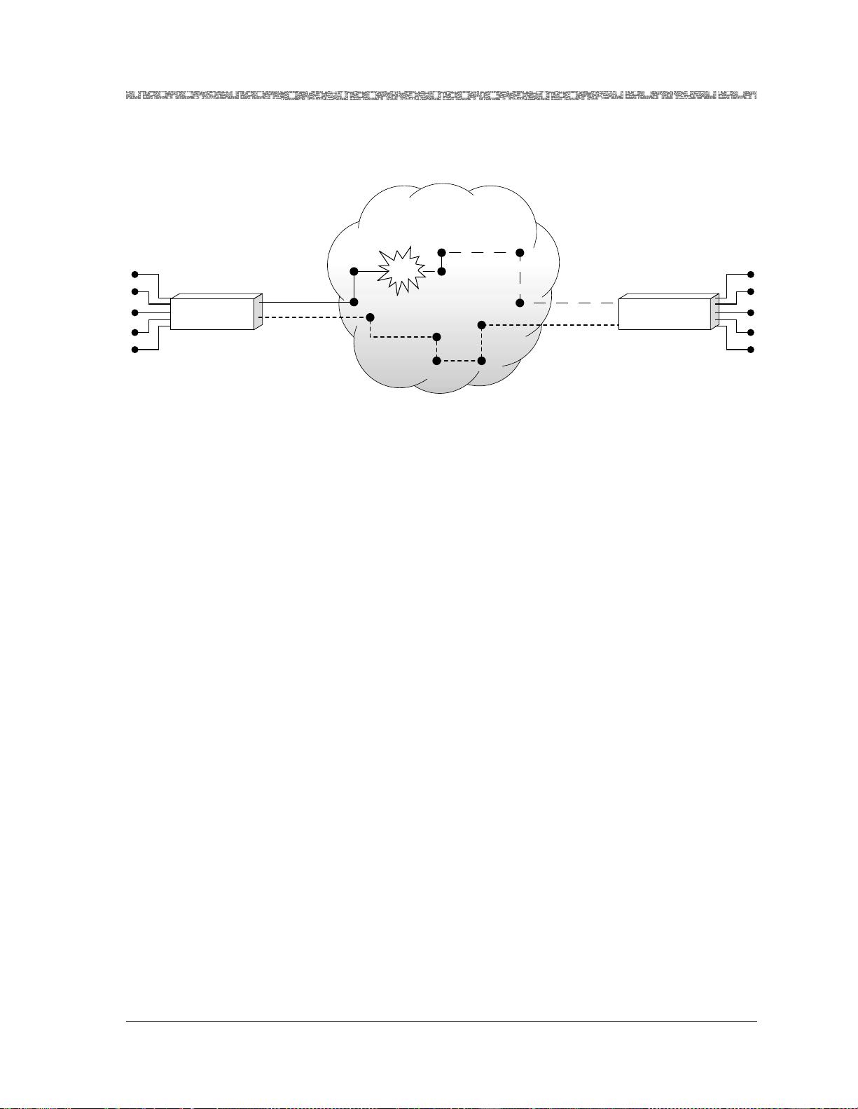
Chapter 3 System Features
Multiservice Media Gateway Software Features
switch the PVCs to the standby link within one second, avoiding service
interruptions under reasonably likely network congestion conditions.
Figure 3-6 illustrates how the alternate rerouting is accomplished.
ATM Network
Multiservice
Media
Gateway
Primary PVC
Standby PVC
Figure 3-6. Automatic Rerouting With Dual-Homed PVCs
If zero errors are detected by the PSAX 1250 system for a user-selectable
interval of 10 seconds, 30 seconds, 1 minute, or 5 minutes (or not allowed),
the system restores the primary link.
Firmware Release Control
The Multiservice Media Gateway CPU has access to the firmware binaries of
all modules present in the Multiservice Media Gateway mainframe. The firmware is downloaded into the random access memory (RAM), into the secondary FLASH of each module, through a dedicated communication channel.
The firmware download is performed under the control of two interworking
functions (IWFs) resident in the Multiservice Media Gateway CPU, and in
the I/O or server module, respectively. Once the binaries are downloaded,
the modules execute the downloaded code that controls the module.
Link failure
Continued
service
Interrupted
service
Primary PVC
Standby PVC
Multiservice
Media
Gateway
You do not need to download an I/O or server module’s firmware separately
from the Multiservice Media Gateway CPU software upgrade. When the
Multiservice Media Gateway software is upgraded using the SRD Download
Configuration window (see Chapter 7, "Upgradi ng and Backing Up the PSAX
System Software"), the system reboots and all firmware of the I/O and server
modules (in the rebooted chassis) is also upgraded.
You can use the firmware upgrade procedure in Chapter 7, "Upgrading and
Backing Up the PSAX System Software"to revert to an older firmware release
if a module is not working properly with its current firmware.
Multiservice Media Gateway I/O modules released with Multiservice Media
Gateway Release 6.0.0 and subsequent releases are supported by the Firmware Release Control feature. The I/O modules that were released before
Multiservice Media Gateway Release 6.0.0 will work in the Multiservice
Media Gateway chassis, but are not supported by the Firmware Release Control feature.
PacketStar® PSAX 1250 Multiservice Media Gateway User Guide, Issue 2 Release 8.0.0
255-700-247 3-31
Page 94

Chapter 3 System Features
Multiservice Media Gateway Software Features
H.248 Media Gateway Access Protocol
The decomposed transit gateway architecture distributes the call control
functionality and the media processing functionality over different network
elements. The advantage gained by decomposition is to decentralize control
from the SS7 network to local networks. Decentralization enables transmission cost savings resulting from enabling gateway peripherals from a central
controller to terminate trunking circuits near the circuit switches from which
they originate.
The PacketStar
PSAX Media Gateway supports a variety of network topologies
for a termination, including, but not limited to:
• PSTN terminations to PSTN terminations
• PSTN terminations to ATM terminations
• One-stage (1+) toll tandem dialing services over ATM
• Fax/modem services (transcoding between TDM network and ATM packet
networks)
For ward Error Correction
The forward error correction (FEC) feature is a combination of functions
designed to protect data transmission in a noisy communications environment, such as traffic transmitted across satellite or line-of-sight radio-frequency circuits. Most of these types of circuits transmit at the rate of 2.048
Mbps or slower. The three stages of FEC are multiple redundancy addressing,
cell encoding, and cell scrambling. Since these FEC functions are applied in
conjunction with the LANET protocol, which helps maintain cell-delineation
capability up to a random 10
-2
bit error rate (BER) with 0.625 percent band-
width overhead, maximum protection is obtained.
Multiple redundancy addressing sets up multiple virtual circuits to the same
destination. The addresses for the circuits are within the error space of the
principal one used for actual transmission. The most probable error patterns
occurring in the address field cause the address to be changed to another
valid one.
To tolerate 2-bit random errors or 5-bit burst errors, 526 addresses are
required for each channel. This is not a serious constraint because high-noise,
low-speed links are normally used by only a small number of users. The
more constraining situation, however , is that the signaling channe l VPI value
0 and the VCI value 5 are within 2 bit-errors of the null cell address (0,0).
Thus, in high-error conditions, signaling is inhibited. The payload type indicator (PTI) and generic flow control (GFC) fields need to be separately protected with the payload.
The user needs only to set up a single connection using a VPI value 0 and a
VCI value in the range from 32 to 92. This provides for 60 simultaneous,
noise-tolerant base connections. Each connection (ATM-to-ATM, VCC, or
PVC) is created between an ATM-enabled port on a Multi-Serial module and
on another ATM port (such as the OC-3c and the STM-1 modules). Internally
within the Multiservice Media Gateway chassis, the connection is routed
through the CPU module for the cell-encoding stage.
PacketStar® PSAX 1250 Multiservice Media Gateway User Guide, Issue 2 Release 8.0.0
3-32 255-700-247
Page 95

Chapter 3 System Features
Multiservice Media Gateway Software Features
Cell encoding is executed by the CPU module on cell payload data destined
for noisy interfaces. Based on a user-selected encoding rate for the connection, source-data cell payloads are divided into six blocks and fed into a Reed
Solomon encoder. The encoded data, now approximately 48 bytes larger, is
loaded into new cell payloads and forwarded to the Multi-Serial module
where the cells are scrambled. The user selects a Reed Solomon encoding rate
with a specific error-correction capability, as follows:
• 1/2 rate
For each data cell, the encoder loads one redundant cell. This rate provides correction of payload cells with 10
-3
BER to 10
-6
BER.
• 1/4 rate
For each set of three data cells, the encoder loads one redundant cell.
-4
This rate provides correction of payload cells with 10
BER to 0 BER.
• 1/8 rate
For each set of seven data cells, the encoder loads one redundant cell.
-5
This rate provides correction of payload cells with 10
BER to 0 BER.
• Dynamically changing rate options (see Table 3-2):
Table 3-2. Rate Options
Bit Error Rate
Cell Encoding Rate
-3
10
Threshold
-4
10
Threshold
-5
10
Threshold
Automatic—low quality 1/2 rate 1/4 rate 1/8 rate
Automatic 1/2 rate 1/2 rate 1/8 rate
Automatic—high quality 1/2 rate 1/2 rate 1/4 rate
When the user selects the 1/2, the 1/4, or the 1/8 rate, the encoder maintains
that selected rate of encoding regardless of actual error conditions. When the
user selects one of the dynamically changing rate options, the encoder
employs the 1/2, 1/4, or 1/8 rate, dynamically adjusting the rate as needed,
depending on the number of errors encountered on the decoding side of the
circuit.
Cell scrambling is a function performed on the DS3 IMA, Enhanced DS1,
Enhanced E1, and Multi-Serial modules. This function moves the first three
bytes of the cell header (the GFC, VPI, and VCI fields) into the payload and
spreads them out to protect against burst errors. This action increases the
burst error tolerance of the header from 5 bits to 54 bits with no cell loss.
Internet Protocol (IP) Throttling
PacketStar® PSAX 1250 Multiservice Media Gateway User Guide, Issue 2 Release 8.0.0
255-700-247 3-33
Page 96

Chapter 3 System Features
Multiservice Media Gateway Software Features
The IP Throttling feature , introduced in Rele ase 7.1.0, limits the rate at which
the CPU module accepts IP traffic (through the
band management virtual port) to prevent the CPU module from being
excessively burdened with traffic. The feature may be applied only to the primary CPU module, not to the backup CPU module.
The feature is initially disabled when the system is running. Once the feature
is enabled, traffic will go through the
ment virtual port by its maximum designated throughput set in the Allowed
Rate field on the IP Throttling window. The feature has no impact on the IP
data path if the feature is disabled. The IP Throttling feature processes only
ingress traffic, not egress traffic.
LANET Protocol
The LANET (limitless ATM network) protocol, coupled with a simple errortolerant addressing scheme, facilitates reliable delivery of ATM cells in a
noisy , low-speed environment. By maintaining the cell extraction capabilities
and strengthening the cell header error protection. LANET offers applicationdependent payload protection, allowing selective implementation of bandwidth-costly, forward-error-correction techniques. It is designed to identify
and extract ATM cells at bit error rates as high as 10
ETHERNET port or by the in-
ETHERNET port or the in-band manage-
-2
.
The main features of LANET include the following:
• Regular framing-bit patterns that enhance cell delineation in noisy envi-
ronments
• Compatibility with traditional link enhancement schemes, su ch as f orward
error correction (FEC) and bit interleaving
• A consistent interface to the higher layer of the protocol stack (that is, the
ATM layer)
• Independence of transmission rate and media
• Natural synchronization with a standard 8-kHz telecommunication clock
The LANET solution offers link quality-dependent header protection while
maintaining maximum compatibility with ATM standards. Figure 3-7 shows
the relationship between LANET and the Open Systems Interconnection
(OSI) model.
PacketStar® PSAX 1250 Multiservice Media Gateway User Guide, Issue 2 Release 8.0.0
3-34 255-700-247
Page 97
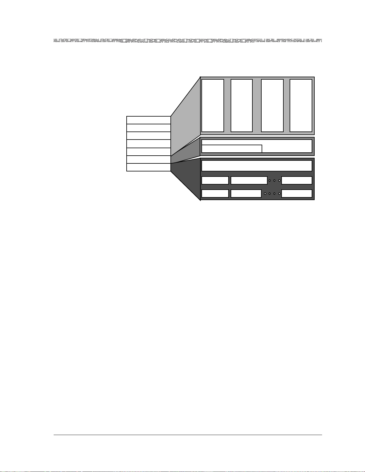
Layer 7
Layer 6
Layer 5
Layer 4
Layer 3
Layer 2
Layer 1
Chapter 3 System Features
Multiservice Media Gateway Software Features
SERVICE-INDEPENDENT ARCHITECTURE
Voice Video Images Data
CELL-BY-CELL ENCRYPTION
Encryption Error Correction Bit Interleaf
Satellite Radio Land Lines
ATM
LANET Protocol
From bits per second to megabits per second
Figure 3-7. The Relationship Between LANET and the OSI Model
The LANET protocol is designed to be active in the upper end of the physical
layer of the OSI seven-layer model. Within a byte-oriented serial data stream,
LANET provides a framing structure around ATM cells for transmission purposes and regular frame-marker bit patterns for cell extraction. Each LANET
frame (2,400 bytes) is subdivided into 45 ATM cells (totaling 2,385 bytes)
with a 15-byte overhead. This structure permits a transmission rate scalable
according to the physical medium.
The 15-byte overhead, accounting for 0.63 percent of the bandwidth,
includes the LANET frame and subframe header s, which are used in conjunction with traditional cell header error-detection methods, such as header
error control (HEC), to enhance cell delineation for noisy environments. The
protocol thus becomes independent of the transmission rate while still naturally synchronizing with an 8-kHz transmission clock via the 2,400-bytesper-frame structure.
Traditionally, block-error correction schemes, such as Reed Solomon coding,
have been used to protect the header. As a simple alternative, the Multiservice Media Gateway system software uses an error-tolerant addressing
scheme (multiple redundancy addressing) that establishes multiple virtual
circuits to the same destination, requiring no special hardware nor modification to the current standard. The addresses for the circuits are within the
error space of the principal address used for actual transmission. The most
probable error patterns occurring in the address field will simply change the
address to another valid address. This approach maintains independence
from the application layer because it encodes the header address within the
PacketStar® PSAX 1250 Multiservice Media Gateway User Guide, Issue 2 Release 8.0.0
255-700-247 3-35
Page 98
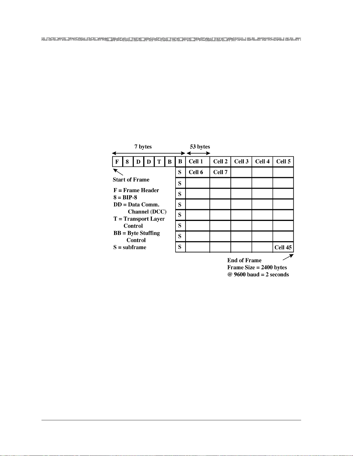
Chapter 3 System Features
Multiservice Media Gateway Software Features
same 10-nibble header space of standard ATM cells. In addition, it avoids the
extra delay (detrimental to CBR traffic) required of multiple header-encoding
schemes.
In practice, to tolerate 2-bit random errors or 5-bit burst errors requires setting up 526 addresses for each channel. This is not a serious constraint
because noisy low-speed links will likely only be used to support a small
number of users.
Finally, given the ability to deliver cells, the payload can now be FEC-protected on each virtual circuit, depending on the error tolerance of the application at the service-specific convergence sublayer (SSCS). Figure 3-8 shows
the LANET frame st ructure.
Figure 3-8. LANET Frame Structure
The LANET subframe functions in the following ways:
• The timely arrival of the header patterns is used as a confidence check,
confirming that the system is properly synchronized.
• In the event of synchronization loss, a Multiservice Media Gateway system
can easily seek and resynchronize to the regular appearance of the simple
header patterns.
PacketStar® PSAX 1250 Multiservice Media Gateway User Guide, Issue 2 Release 8.0.0
3-36 255-700-247
Page 99

Multiservice Media Gateway Software Features
Operations, Administration, and Maintenance (OAM)
Chapter 3 System Features
Overview of OAM The Operations, Administration, and Maintenance (OAM) feature, available
on all PacketStar
Multiservice Media Gateway systems gives Public Service
Providers a way to detect and receive reports on abnormal behavior in virtual
path connections (VPCs) and virtual channel connections (VCCs) in an ATM
network.
OAM performs this function by injecting cells which contain OAM information into the network traffic. This information is referred to as a flow. In order
for an OAM flow to function properly, there must be an exchange of operations information between the various nodes in a network. In the case of an
ATM netw or k, t hi s inf orma ti on is exchan ged o ver pe rma nent and sw it ch virtual connections, with F4 flows designated for OAM traffic over a virtual
path connection, and F5 flows designated for OAM traffic over a virtual
channel connection. These flows provide details about defect and failure
detection, performance monitoring, and defect information.
Note: For information about using OAM to en able trunk co nditioning for
upstream or downstream interworking, see the Trunk Conditioning
Application Note for PacketStar
®
Multiservice Media Gateways.
OAM Cell Characteristics
OAM cells are bidirectional. They follow the same physical and logical route
as user payload cells. Each flow has two variants: one checks a particular segment, and the other checks the en d-to-end flow.
• Segments are indicated by a virtual channel identifier (VCI) of 3 for F4
flows, or a payload type of 4 for F5 flows.
• End-to-end flows are indicated by a VCI of 4 for F4 flows, or a payload
type of 5 for F5 flows.
OAM segments can be a single ATM link, or group of interconnected links on
an ATM connection, although it is important to note that not all links belong
to segments. One or more OAM segments can be de fined along a VC , VPC, or
VCC connection, although these segments cannot overlap, nor can they be
nested. A source point of segments acting in a downstream direction will terminate unexpected OAM cells coming from the upstream side of a connection.
End points, either as part of a full connection, or of a segment, use activation
procedures to request continuity checking with the opposite end point. Endto-end continuity checks and segment continuity checks are also supported.
The requesting end point specifies the direction of the continuity checking
(from the requesting end point, to the requesting end point, or in both directions). If the far end accepts the request, the specified source point (or points)
starts sending continuity checks periodically to the receiving point.
A connection point (CP) along a connection inserts new OAM cells according
to defined OAM cell usage and procedures. It does not terminate the OAM
flow, except when loopbacks are performed.
The format of an OAM cell is shown in Figure 3-9:
PacketStar® PSAX 1250 Multiservice Media Gateway User Guide, Issue 2 Release 8.0.0
255-700-247 3-37
Page 100

Chapter 3 System Features
Multiservice Media Gateway Software Features
OAM ATM Layer Flows
Header
Payload
OAM Function
Type Reserved
Header
Figure 3-9. OAM Cell Fields
44 6 10360 bits (45 bytes)
OAM
Function-specific field
Cell
Type
Error
Detection
Code
• Header: this is the same as the ATM cell header
• OAM Cell Type: the management type (fault, activation/deactivation)
• OAM Function Type: the specific function (AIS, RDI, continuity check,
loopback, forward monitoring, backward reporting, and so on)
• Function-Specific Field: data required for the specific function
• Reserved: reserved for further specification
• EDC: CRC-10 error detection code computed over the cell payload (except
the CRC-10 field itself) and used to check for data corruption
OAM has two flows of management information: F4 and F5. F4/F5 in-band
maintenance flows are defined at the ATM layer for the VPC and VCC level,
respectively. F4 is used for path-level connections, where the virtual path
(VP) flows are identified by reserved values within the path. F5 is used for
circuit-level connections, where the circuit virtual channel (VC) flows are
identified by the payload type (PT) indicator field values.
These flows can be initiated at, or after, a connection setup by:
• call process functions
• OAM functions, or
• the network operator.
The hierachial structure of OAM flows is shown in Figure 3-9:
PacketStar® PSAX 1250 Multiservice Media Gateway User Guide, Issue 2 Release 8.0.0
3-38 255-700-247
 Loading...