

Page 1

PacketStar® PSAX Enhanced Router Module
User Guide
Model 23N41
®
for the PacketStar
Issue 1, March 2004
System Software Release 9.1.0
®
Navis
AQueView® EMS Release 9.1.0
PSAX Multiservice Media Gateways
Doc. No.: 255-700-614
Page 2

Copyright © 2004 by Lucent T echnologies. All rights reserved.
For trademark, regulatory compliance, and related legal information, see
the "Legal Notices, Safety, and Regulatory Information" section.
Page 3

Legal Notices, Safety, and Regulatory
Copyright
Trademarks
Information
Copyright © 2004 by Lucent T echnologies. All rights reserved.
This material is protected by the copyright laws of the United States and
other countries. It may not be reproduced, distributed, or altered in any fashion by any entity (either internal or external to Lucent Technologies), except
in accordance with applicab le agreements , contracts o r licensing, wi thout the
express written consent of the originating organization and the business
management owner of the material.
This document was prepared by the Information Products and Training
(IP&T) Associates Team of Lucent Technologies, PacketStar PSAX products.
Offices are located in Landover, Maryland, USA.
PacketStar, AQueView, Lucent, Lucent Technologies, and the Lucent Technolo-
gies logo are register ed tradema rks of Lucent Technologies in the USA. Other
product and brand names mentioned in this guide are trademarks or registered trademarks of their respective owners.
Notices
The information in this document is for informational use only, is subject to
change without notice, and should not be construed as a commitment by
Lucent Technologies, Inc. This document is without warranty of any kind,
either expressed or implied. Lucent Technologies, Inc. assumes no responsibility for any errors, inaccuracies, or omissions. Neither is any liability
assumed for damages resulting from the use of the information or instructions contained herein. Lucent Technologies, Inc. is not responsible for any
damage or loss to your data or equipment resulting either directly or indirectly from use of this document.
Warranty Information
Software and Hardware Limited Warranties
Lucent Technologies provides a 90-day limited software warranty, and a oneyear limited hardware warranty on this product. Refer to the Software License
and Limited Warranty Agreement and the Lucent Technologies InterNetworking Systems Global Warranty that accompanied your package for more information.
PacketStar® PSAX Enhanced Router Module User Guide, Issue1 Release9.1.0
255-700-614 iii
Page 4

Legal Notices, Safety, and Regulatory Information
Safety Warnings and Information
Warr anty Warnings
!
WARNING:
When inserting modules into the chassis, slide them gently, not forcefully. Excessive force may cause the modules to be seated improperly in
the chassis, and result in possible damage to the module or the chassis.
Install or remove modules one at a time. Doing this aids in preventing
the PSAX system from indicating any erroneous failure messages, and
allows the PSAX system time to reinitialize and display the accurate configuration of the module that is inserted.
!
CAUTION:
Modifying or tampering with PSAX chassis components may void your
warranty. Any modification to this equipment not expressly authorized
by Lucent Technologies may void your granted authority to operate such
equipment.
!
CAUTION:
Shipping the chassis with removable I/O, server, or CPU modules
installed may cause damage to the chassis and the modules. Damage to
any of the components in the system resulting from shipping the chassis
with removable modules installed will void your warranty.
Safety Warnings and Information
When installing and operating the Enhanced Router module, follow the
safety guidelines provided in the PacketStar
accompanies this product, to help prevent serious personal injury and damage to the Enhanced Router module. Please read all warnings and instructions supplied before beginning installation or configuration of this module.
In addition to the general safety information provided, you should also refer
to the text in the PacketStar PSAX installation guides for other important
safety information and procedures.
Regulatory Standards Compliance
Safety and Electromagnetic Compatibility
The following PacketStar PSAX systems are compliant with applicable safety
and EMC standards when configured with the Enhanced Router module
module (model 23N41):
• PSAX 1000 system
• PSAX 1250 system
• PSAX 2300 system
• PSAX 4500 system
®
PSAX Safety Guidelines, which
PacketStar® PSAX Enhanced Router Module User Guide, Issue 1 Release 9.1.0
iv 255-700-614
Page 5

Legal Notices, Safety, and Regulatory Information
Regulatory Statements
Please refer to the PacketStar PSAX 1000, PSAX 1250, PSAX 2300, or
PSAX 4500 Multiservice Media Gateway installation guide for details on
safety and EMC standards compliance.
Regulatory Statements
European Union Regulatory Statement
CE Marking Hereby, Lucent Technologies declares that the PacketStar PSAX 1000
(-48 V dc and 220 Vac), PSAX 1250 (-48 V dc and 220 V ac), PSAX 2300,
and PSAX 4500 Multiservice Media Gateways, including the equipment documented in this publication, are in compliance with the essential requirements and other relevant provisions of the following Council Directives:
• Low Voltage 72/23/EEC
• Electromagnetic Compatibility (EMC) 89/336/EEC
• Radio Equipment and Telecommunications Terminal Equipment
1999/5/EC
The Lucent PacketStar PSAX Multiservice Media Gateways deployed in the
European Economic Area (EEA) are intended for connection to E1, E3,
STM-1, and STM-4c networks. The EC Declarations of Conformity may be
viewed or printed at the following public-access Internet site:
http://www.lucentdocs.com/ins
EU-regulativer
CE-mærkning Lucent Technologies erklærer hermed at PacketStar PSAX 1000 (-48 V dc og
220 v vekselstrøm), PSAX 1250 (-48 V dc og 220 v vekselstrøm), PSAX 2300,
og PSAX 4500 Multiservice Media Gateways, inkl. det udstyr der findes
behandlet i denne dokumentation, er i overensstemmelse med fø lg ende EUdirektiver:
• Lavspændingsdirektivet 72/23/EEC
• EMC-direktivet 89/336/EEC
• Direktivet om radio og teleterminaludstyr 1999/5/EC
Lucent PacketStar PSAX Multiservice Media Gateways, anvendt i EØS
(Europæiske Økonomiske Samarbejde) skal forbindes med E1, E3, STM-1 og
STM-4c netværk. EU-overensstemmelseserklæringen er at finde på følgende
internet side hvorfra den også kan udskrives:
http://www.lucentdocs.com/ins
PacketStar® PSAX Enhanced Router Module User Guide, Issue1 Release9.1.0
255-700-614 v
Page 6
Legal Notices, Safety, and Regulatory Information
Regulatory Statements
Behördliche Standard-CE-Kennzeichnung für die Europäische Gemeinschaft
CE-Markierung Hiermit erklärt Lucent Technologies, dass die PacketStar PSAX 1000
(-48 V DC
PSAX 4500 Multiservice Media Gateways, einschließlich den in dieser Publikation dokumentierten Anlagen, die notwendigen Anforderungen und
anderen relevanten Vorschriften der folgenden Council-Direktiven einhalten:
• Niederspannungsdirektive 72/23/EEC
• Elektromagnetische Verträglichkeit (EMC) 89/336/EEC
• Funkgeräte und Funkverkehr-Endeinrichtungen 1999/5/EC
Die Lucent PacketStar PSAX Multiservice Media Gateways, die in der
Europäischen Gemeinschaft im Einsatz stehen, dienen zum Anschluss an folgende Netztypen: E1, E3, STM-1 und STM-4c. Die Konformitätserklärung für
die Europäische Gemeinschaft kann auf folgendem, öffentlich zugänglichem
Internet-Site eingesehen oder ausgedruckt werden:
http://www.lucentdocs.com/ins
und 220 V~
), PSAX 1250 (-48 V DC
und 220 V~
), PSAX 2300, und
&( /XFHQW7HFKQRORJLHV 3DFNHW6WDU PSAX1000 (-48 Vdc
9DF), PS AX1250 (-48 Vdc 9DF), PSAX2300, PSAX
Multiservice Media Gateways,
• (2.
• + (0&(2.
• (.
/XFHQW3DFNHW6WDU36$;0XOWLVHUYLFH0HGLD*DWHZD\V
((670
http://www.lucentdocs.com/ins
670F7
Euroopan unionin sääntelystandardi
CE-merkintä Lucent Technologies vakuuttaa täten, että PacketStar PSAX 1000 (-4 8 V dc ja
220 V vaihtovirtaa), PSAX 1250 (-48 V dc ja 220 V vaihtovirtaa), PSAX 2300,
ja PSAX 4500 Media Gatewayt ja tässä julkaisussa dokumentoidut laitteet,
täyttävät seuraavien neuvoston direktiivien keskeiset va atimukset ja a siaankuuluvat määräykset:
• Pienjännite 72/23/EY
• Sähkömagneettinen yhteensopivuus (EMC) 89/336/EY
PacketStar® PSAX Enhanced Router Module User Guide, Issue 1 Release 9.1.0
vi 255-700-614
Page 7

Legal Notices, Safety, and Regulatory Information
Regulatory Statements
• Radiolaitteet ja telepäätelaitteet 1999/5/EY
Lucent PacketStar PSAX Multiservice Media Gatewayt, joita käytetään
Euroopan talousalueella, on tarkoitettu liitettäväksi E1-, E3-, STM-1- ja
STM-4c-verkkoihin. EU:n vaatimustenmukaisuusvakuutus voidaan nähdä
tai tulostaa seuraavalta julkiselta Internet-sivulta:
http://www.lucentdocs.com/ins
Norme réglementaire de l’Union européenne
Label CE Lucent Technologies déclare en ceci que les passerelles de média multiser-
vices PacketStar PSAX 1000 (-48 V c.c.
220 V ca
tielles et autres dispositions pertinentes des directives suivantes du Conseil:
• Basse tensio n 72/23/ CE E
• Compatibilité éle ctromagnétique (CEM) 89/336/CEE
• Matériel radio et terminaux de télécommunications 1999/5/CE
), PSAX 2300, et PSAX 4500 sont conformes aux exigences essen-
et 220 V ca
), PSAX 1250 (-48 V c.c.
et
Les passerelles de média multiservices PacketStar PSAX de Lucent, commercialisées dans l’Espace économique européen sont destinées aux connexions
à des réseaux E1, E3, STM-1 et STM-4c. Les déclarations de conformité CE
peuvent être consultées ou imprimées à partir du site Interne t d’accès public:
http://www.lucentdocs.com/ins
Normativa dell’Unione Europea
Apposizione del marchio CE
La Lucent Technologies dichiara che i gateway multiservizio PacketStar
PSAX 1000 (-48 V dc e 220 V c.a.), PSAX 1250 (-48 V dc e 220 V c.a.),
PSAX 2300, e PSAX 4500 inclusi quelli documentati in seguito, rispondono ai
requisiti essenziali ed ad altre norme rilevanti delle seguenti direttive del
Consiglio:
• Direttiva 72/23/CEE “Basse tensioni”
• Direttiva 89/336/CEE sulla compatibilità elettromagnetica
• Direttiva 1999/5/CE riguardante le apparecchiature radio e le apparecchia-
ture terminali di telecomunicazione
I gateway multiservizio PacketStar PSAX della lucent, impiegati nell’area eco-
nomica europea (EEA), sono concepiti per il collegamento con reti E1, E3,
STM-1 e STM-4c. Le dichiarazioni di conformità CE possono essere visionati
o stampati presso il seguente sito Internet di pubblico accesso:
http://www.lucentdocs.com/ins
PacketStar® PSAX Enhanced Router Module User Guide, Issue1 Release9.1.0
255-700-614 vii
Page 8

Legal Notices, Safety, and Regulatory Information
Regulatory Statements
Norm van de Europese Unie
CE-markering Lucent Technologies verklaart hierbij dat de PacketStar PSAX 1000 (-48 V dc
en 220V wisselstroom), PSAX 1250 (-48 V dc en 220V wisselstroom),
PSAX 2300, en PSAX 4500 Multiservice Media Gateways voldoen aan de
essentiële vereisten en andere relevante bepalingen van de volgende Richtlijnen van de Raad:
• Laagspanning 72/23/EEG
• Elektromagnetische compatibiliteit (EMC) 89/336/EEG
• Radioapparatuur en telecommunicatie-eindapparatuur 1999/5/EG
De Lucent PacketStar PSAX Multi Service Media Gateways die in de Europese
Economische Ruimte (EER) zijn ingezet, zijn bestemd voor aansluiting op E1,
E3, STM-1 en STM-4c netwerken. DE EU-verklar ingen van overeenstemming kunnen worden bekek en of af gedrukt o p de volgende I nternet -site met
openbare toeg a ng :
http://www.lucentdocs.com/ins
Padrão Regulador da União Europeia
Marca CE A Lucent Technologies vem por este meio declarar que os Concentradores de
Acesso PacketStar PSAX 1000 (-48 V dc e 220V CA), PSAX 1250 (-48 V dc e
220V CA), PSAX 2300, e PSAX 4500 obedecem aos requisitos essenciais e a
outras disposições relevantes das seguintes Directivas do Conselho:
• Baixa Voltagem 72/23/EEC
• Compatibilidade Electromagnética (EMC) 89/336/EEC
• Equipamento de Rádio e Equipamento Terminal de Telecomunicações
1999/5/EC
Os Concentradores de Acesso PacketStar PSAX da Lucent instalados na Área
Económica Europeia (EEA) foram concebidos para serem ligados a redes do
tipo E1, E3, STM-1 e STM-4c. As Declarações de Conformidade CE podem se r
vistas ou impressas no seguinte sítio de acesso público da Internet:
http://www.lucentdocs.com/ins
Norma reguladora de la Unión Europea
Marcas de la CE Por el presente, Lucent Technologies declara que las pasarelas de medios
multiservicio PacketStar PSAX 1000 (-48 V cc y 220 V ca), PSAX 1250
(-48 V cc y 220 V ca), PSAX 2300, y PSAX 4500 Multiservice Media Gateways, inclusive el equipo documentado en esta publicación, están en conformidad con los requisitos esenciales y otras disposiciones pertinentes de las
siguientes directrices del consejo:
• Bajo voltaje 72/23/EEC
• Compatibilidad electromagnética (EMC) 89/336/EEC
• Equipo de radio y equipo de terminales de telecomunicaciones 1999/5/EC
PacketStar® PSAX Enhanced Router Module User Guide, Issue 1 Release 9.1.0
viii 255-700-614
Page 9

Legal Notices, Safety, and Regulatory Information
Regulatory Statements
Las pasarelas de medios multiservicio Lucent PacketStar PSAX Multiservice
Media Gateways desplegadas en el área económica europea (European Economic Area, EEA) están destinadas a conectarse en redes E1, E3, STM-1 y
STM-4c. Las declaraciones de conformidad de la CE pueden verse o
imprimirse en el siguiente sitio Internet de acceso público:
http://www.lucentdocs.com/ins
Europeiska unionens standardförordning
CE-märkning Lucent Technologies deklarerar härmed att PacketStar PSAX 1000
(-48 V likström
växelström
och 220 V växelström
), PSAX 2300, och PSAX 4500 Multiservice Media Gateways, inklusive den i denna publikation dokumenterade utrustning, uppfyller de
väsentliga kraven och andra relevanta bestämmelser som gäller enligt följande Europarådsdirektiv:
• Lågspänning 72/23/EEC
• Elektromagnetisk kompatibilitet (EMC) 89/336/EEC
• Radioutrustning och telekommunikationskopplingsutrustning 1999/5/EC
), PSAX 1250 (-48 V likström
och 220 V
Lucent PacketStar PSAX Multiservice Media Gateways, som är placerad i EEA
(European Economic Area), är avsedd för att anslutas till E1, E3, STM-1 och
STM-4c nätverk. Europarådet s Kon for mite tsd ekl ar at io ner ka n ses på bild-
skärm eller skrivas ut på följande, för allmänheten tillgängliga Internet-ställe:
http://www.lucentdocs.com/ins
PacketStar® PSAX Enhanced Router Module User Guide, Issue1 Release9.1.0
255-700-614 ix
Page 10

Legal Notices, Safety, and Regulatory Information
Regulatory Statements
PacketStar® PSAX Enhanced Router Module User Guide, Issue 1 Release 9.1.0
x 255-700-614
Page 11

Contents
Legal Notices, Safety, and Regulatory Information . . . . . . . . . . . . . . . . . iii
Copyright . . . . . . . . . . . . . . . . . . . . . . . . . . . . . . . . . . . . . . . . . . . . . . . . . . . . . . . . . . . . . iii
Trademarks . . . . . . . . . . . . . . . . . . . . . . . . . . . . . . . . . . . . . . . . . . . . . . . . . . . . . . . . . . . . iii
Notices . . . . . . . . . . . . . . . . . . . . . . . . . . . . . . . . . . . . . . . . . . . . . . . . . . . . . . . . . . . . . . . iii
Warranty Information . . . . . . . . . . . . . . . . . . . . . . . . . . . . . . . . . . . . . . . . . . . . . . . . . . . . . iii
Software and Hardware Limited Warranties . . . . . . . . . . . . . . . . . . . . . . . . . . . . . . . . . iii
Warranty Warnings . . . . . . . . . . . . . . . . . . . . . . . . . . . . . . . . . . . . . . . . . . . . . . . . . . . iv
Safety Warnings and Information . . . . . . . . . . . . . . . . . . . . . . . . . . . . . . . . . . . . . . . . . . . . iv
Regulatory Standards Compliance . . . . . . . . . . . . . . . . . . . . . . . . . . . . . . . . . . . . . . . . . . . iv
Regulatory Statements . . . . . . . . . . . . . . . . . . . . . . . . . . . . . . . . . . . . . . . . . . . . . . . . . . . . v
European Union Regulatory Statement . . . . . . . . . . . . . . . . . . . . . . . . . . . . . . . . . . . . v
Contents . . . . . . . . . . . . . . . . . . . . . . . . . . . . . . . . . . . . . . . . . . . . . . . . . . . . xi
List of Figures . . . . . . . . . . . . . . . . . . . . . . . . . . . . . . . . . . . . . . . . . . . . . xviii
List of Tables . . . . . . . . . . . . . . . . . . . . . . . . . . . . . . . . . . . . . . . . . . . . . . . xxi
1 Getting Started . . . . . . . . . . . . . . . . . . . . . . . . . . . . . . . . . . . . . . . . . . . . . . . . 1-1
Purpose of This Guide . . . . . . . . . . . . . . . . . . . . . . . . . . . . . . . . . . . . . . . . . . . . . . . . . . . .1-1
Audience for This Guide . . . . . . . . . . . . . . . . . . . . . . . . . . . . . . . . . . . . . . . . . . . . . . . . . .1-1
What You Should Know . . . . . . . . . . . . . . . . . . . . . . . . . . . . . . . . . . . . . . . . . . . . . . . . . .1-1
Related Reading . . . . . . . . . . . . . . . . . . . . . . . . . . . . . . . . . . . . . . . . . . . . . . . . . . . . . . . .1-1
Lucent Technologies Information Products . . . . . . . . . . . . . . . . . . . . . . . . . . . . . . . . .1-1
Product Information Library . . . . . . . . . . . . . . . . . . . . . . . . . . . . . . . . . . . . . . . . .1-1
Printed Documents. . . . . . . . . . . . . . . . . . . . . . . . . . . . . . . . . . . . . . . . . . . . . . . .1-2
Other Publications . . . . . . . . . . . . . . . . . . . . . . . . . . . . . . . . . . . . . . . . . . . . . . . . . . .1-2
About Lucent Technologies . . . . . . . . . . . . . . . . . . . . . . . . . . . . . . . . . . . . . . . . . . . . . . . .1-2
About the PacketStar PSAX Product Family . . . . . . . . . . . . . . . . . . . . . . . . . . . . . . . . . . . .1-2
PSAX 1000 Multiservice Media Gateway. . . . . . . . . . . . . . . . . . . . . . . . . . . . . . . . . . .1-2
PSAX 1250 Multiservice Media Gateway. . . . . . . . . . . . . . . . . . . . . . . . . . . . . . . . . . .1-3
PSAX 2300 Multiservice Media Gateway. . . . . . . . . . . . . . . . . . . . . . . . . . . . . . . . . . .1-3
PSAX 4500 Multiservice Media Gateway. . . . . . . . . . . . . . . . . . . . . . . . . . . . . . . . . . .1-4
Text Conventions . . . . . . . . . . . . . . . . . . . . . . . . . . . . . . . . . . . . . . . . . . . . . . . . . . . . . . .1-4
PacketStar® PSAX Enhanced Router Module User Guide, Issue 1 Release 9 .1.0
255-700-614 xi
Page 12

Contents
Text Types Used in This Document. . . . . . . . . . . . . . . . . . . . . . . . . . . . . . . . . . . . . . . 1-4
Icons and Symbols . . . . . . . . . . . . . . . . . . . . . . . . . . . . . . . . . . . . . . . . . . . . . . . . . . 1-5
Use of Command Description Tables . . . . . . . . . . . . . . . . . . . . . . . . . . . . . . . . . . . . . 1-5
Use of Field Description Tables. . . . . . . . . . . . . . . . . . . . . . . . . . . . . . . . . . . . . . . . . . 1-6
Selecting Options, Fields, and Commands. . . . . . . . . . . . . . . . . . . . . . . . . . . . . . . . . 1-6
Help Information . . . . . . . . . . . . . . . . . . . . . . . . . . . . . . . . . . . . . . . . . . . . . . . . . . . . . . . 1-8
Technical Support . . . . . . . . . . . . . . . . . . . . . . . . . . . . . . . . . . . . . . . . . . . . . . . . . . . . . . 1-9
Before You Begin. . . . . . . . . . . . . . . . . . . . . . . . . . . . . . . . . . . . . . . . . . . . . . . . . . . . . . . 1-9
Comments on This Guide . . . . . . . . . . . . . . . . . . . . . . . . . . . . . . . . . . . . . . . . . . . . . . . . 1-9
2 Module Description . . . . . . . . . . . . . . . . . . . . . . . . . . . . . . . . . . . . . . . . . . . . .2-1
Functional Description . . . . . . . . . . . . . . . . . . . . . . . . . . . . . . . . . . . . . . . . . . . . . . . . . . . 2-1
Feature Summary . . . . . . . . . . . . . . . . . . . . . . . . . . . . . . . . . . . . . . . . . . . . . . . . . . . . . . 2-1
Basic Features . . . . . . . . . . . . . . . . . . . . . . . . . . . . . . . . . . . . . . . . . . . . . . . . . . . . . . 2-1
Routing and ARP Features. . . . . . . . . . . . . . . . . . . . . . . . . . . . . . . . . . . . . . . . . . . . . 2-2
VPN Features. . . . . . . . . . . . . . . . . . . . . . . . . . . . . . . . . . . . . . . . . . . . . . . . . . . . . . . 2-3
Connection Features . . . . . . . . . . . . . . . . . . . . . . . . . . . . . . . . . . . . . . . . . . . . . . . . . 2-3
Other Features . . . . . . . . . . . . . . . . . . . . . . . . . . . . . . . . . . . . . . . . . . . . . . . . . . . . . 2-3
Maximum Capacities. . . . . . . . . . . . . . . . . . . . . . . . . . . . . . . . . . . . . . . . . . . . . . . . . 2-3
Software Features . . . . . . . . . . . . . . . . . . . . . . . . . . . . . . . . . . . . . . . . . . . . . . . . . . . . . . 2-4
Traffic Flow . . . . . . . . . . . . . . . . . . . . . . . . . . . . . . . . . . . . . . . . . . . . . . . . . . . . . . . . 2-4
Operating Modes of the Enhanced Router Module Module. . . . . . . . . . . . . . . . . . . . 2-4
IP Application in the Multiservice Media Gateway . . . . . . . . . . . . . . . . . . . . . . . . . . . 2-5
Module Operation . . . . . . . . . . . . . . . . . . . . . . . . . . . . . . . . . . . . . . . . . . . . . . . . . . 2-5
Enhanced Router Database Conversion. . . . . . . . . . . . . . . . . . . . . . . . . . . . . . . . . . . 2-6
Enhanced Router-to-ATM OAM Interworking . . . . . . . . . . . . . . . . . . . . . . . . . . . . . . 2-6
Class of Service . . . . . . . . . . . . . . . . . . . . . . . . . . . . . . . . . . . . . . . . . . . . . . . . . . . . . 2-6
Capacity of Classification Tables . . . . . . . . . . . . . . . . . . . . . . . . . . . . . . . . . . . . . 2-7
DSCP (Diffserv) Classification . . . . . . . . . . . . . . . . . . . . . . . . . . . . . . . . . . . . . . . 2-7
Subchannel Classification . . . . . . . . . . . . . . . . . . . . . . . . . . . . . . . . . . . . . . . . . . 2-7
Fixed Classification . . . . . . . . . . . . . . . . . . . . . . . . . . . . . . . . . . . . . . . . . . . . . . . 2-7
IP Interface and Connection Operations . . . . . . . . . . . . . . . . . . . . . . . . . . . . . . . 2-7
Ingress DiffServ Mapping Table. . . . . . . . . . . . . . . . . . . . . . . . . . . . . . . . . . . . . . 2-8
Virtual Routing . . . . . . . . . . . . . . . . . . . . . . . . . . . . . . . . . . . . . . . . . . . . . . . . . . . . . 2-8
Unnumbered Interfaces. . . . . . . . . . . . . . . . . . . . . . . . . . . . . . . . . . . . . . . . . . . . . . . 2-9
RIP Version 2 Features. . . . . . . . . . . . . . . . . . . . . . . . . . . . . . . . . . . . . . . . . . . . . . . 2-11
Authentication . . . . . . . . . . . . . . . . . . . . . . . . . . . . . . . . . . . . . . . . . . . . . . . . . 2-11
Multicasting . . . . . . . . . . . . . . . . . . . . . . . . . . . . . . . . . . . . . . . . . . . . . . . . . . . 2-11
Address Resolution Protocol (ARP). . . . . . . . . . . . . . . . . . . . . . . . . . . . . . . . . . . . . . 2-11
Static Routing . . . . . . . . . . . . . . . . . . . . . . . . . . . . . . . . . . . . . . . . . . . . . . . . . . . . . 2-12
PacketStar® PSAX Enhanced Router Module User Guide, Issue 1 Release 9.1.0
xii 255-700-614
Page 13

Contents
Static IP Routing Overview . . . . . . . . . . . . . . . . . . . . . . . . . . . . . . . . . . . . . . . . .2-12
IP Route Table . . . . . . . . . . . . . . . . . . . . . . . . . . . . . . . . . . . . . . . . . . . . . . . . . .2-12
IP Filtering . . . . . . . . . . . . . . . . . . . . . . . . . . . . . . . . . . . . . . . . . . . . . . . . . . . . . . . .2-13
Enhanced Router Module Applications . . . . . . . . . . . . . . . . . . . . . . . . . . . . . . . . . . . . . .2-14
1xEVDO Applications . . . . . . . . . . . . . . . . . . . . . . . . . . . . . . . . . . . . . . . . . . . . . . . .2-14
QoS Transport Application . . . . . . . . . . . . . . . . . . . . . . . . . . . . . . . . . . . . . . . . . . . .2-15
Hardware Features . . . . . . . . . . . . . . . . . . . . . . . . . . . . . . . . . . . . . . . . . . . . . . . . . . . . .2-16
Hardware Specifications . . . . . . . . . . . . . . . . . . . . . . . . . . . . . . . . . . . . . . . . . . . . . .2-16
Performance and Power Specifications . . . . . . . . . . . . . . . . . . . . . . . . . . . . . . . . . . .2-17
LED Indicators. . . . . . . . . . . . . . . . . . . . . . . . . . . . . . . . . . . . . . . . . . . . . . . . . . . . . .2-17
3 Configuring VPNs Using the Console Interface. . . . . . . . . . . . . . . . . . . . . . . 3-1
Overview of This Chapter . . . . . . . . . . . . . . . . . . . . . . . . . . . . . . . . . . . . . . . . . . . . . . . . .3-1
Before You Begin . . . . . . . . . . . . . . . . . . . . . . . . . . . . . . . . . . . . . . . . . . . . . . . . . . . . . . .3-1
Configuring the Module . . . . . . . . . . . . . . . . . . . . . . . . . . . . . . . . . . . . . . . . . . . . . . . . . .3-1
Hierarchy of the Enhanced Router Configuration . . . . . . . . . . . . . . . . . . . . . . . . . . . .3-2
Accessing the VPN Configuration Table. . . . . . . . . . . . . . . . . . . . . . . . . . . . . . . . . . . .3-2
Configuring VPNs . . . . . . . . . . . . . . . . . . . . . . . . . . . . . . . . . . . . . . . . . . . . . . . . . . . . . . .3-5
Bringing VPNs Into and Out of Service . . . . . . . . . . . . . . . . . . . . . . . . . . . . . . . . . . .3-11
Deleting VPNs. . . . . . . . . . . . . . . . . . . . . . . . . . . . . . . . . . . . . . . . . . . . . . . . . . . . . .3-11
Viewing ICMP Statistics . . . . . . . . . . . . . . . . . . . . . . . . . . . . . . . . . . . . . . . . . . . . . .3-12
Viewing IP Statistics . . . . . . . . . . . . . . . . . . . . . . . . . . . . . . . . . . . . . . . . . . . . . . . . .3-15
Configuring IP Interfaces. . . . . . . . . . . . . . . . . . . . . . . . . . . . . . . . . . . . . . . . . . . . . . . . .3-19
Setting the Values for IP Interfaces . . . . . . . . . . . . . . . . . . . . . . . . . . . . . . . . . . . . . .3-19
Class of Service Configuration Examples. . . . . . . . . . . . . . . . . . . . . . . . . . . . . . . . . .3-25
Configuring Unnumbered Interfaces. . . . . . . . . . . . . . . . . . . . . . . . . . . . . . . . . . . . .3-26
Viewing Interface Statistics . . . . . . . . . . . . . . . . . . . . . . . . . . . . . . . . . . . . . . . . . . . .3-26
Deleting an IP Interface. . . . . . . . . . . . . . . . . . . . . . . . . . . . . . . . . . . . . . . . . . . . . . .3-28
Viewing and Configuring DHCP Servers . . . . . . . . . . . . . . . . . . . . . . . . . . . . . . . . . . . . .3-29
Viewing and Updating RIP Interfaces. . . . . . . . . . . . . . . . . . . . . . . . . . . . . . . . . . . . . . . .3-32
Viewing the RIP Interface Table. . . . . . . . . . . . . . . . . . . . . . . . . . . . . . . . . . . . . . . . .3-32
Updating a RIP Interface . . . . . . . . . . . . . . . . . . . . . . . . . . . . . . . . . . . . . . . . . . . . . .3-34
Deleting an RIP Interface. . . . . . . . . . . . . . . . . . . . . . . . . . . . . . . . . . . . . . . . . . . . . .3-38
Viewing RIP Interface Statistics . . . . . . . . . . . . . . . . . . . . . . . . . . . . . . . . . . . . . . . . .3-38
Viewing IP Addresses . . . . . . . . . . . . . . . . . . . . . . . . . . . . . . . . . . . . . . . . . . . . . . . . . . .3-40
Configuring IP Filter Rules . . . . . . . . . . . . . . . . . . . . . . . . . . . . . . . . . . . . . . . . . . . . . . . .3-41
Configuring Static IP Routes . . . . . . . . . . . . . . . . . . . . . . . . . . . . . . . . . . . . . . . . . . . . . .3-46
Accessing the IP Route Table. . . . . . . . . . . . . . . . . . . . . . . . . . . . . . . . . . . . . . . . . . .3-46
Deleting Static IP Routes. . . . . . . . . . . . . . . . . . . . . . . . . . . . . . . . . . . . . . . . . . . . . .3-51
Configuring ARP . . . . . . . . . . . . . . . . . . . . . . . . . . . . . . . . . . . . . . . . . . . . . . . . . . . . . . .3-51
PacketStar® PSAX Enhanced Router Module User Guide, Issue 1 Release 9 .1.0
255-700-614 xiii
Page 14

Contents
Viewing ARP Entries . . . . . . . . . . . . . . . . . . . . . . . . . . . . . . . . . . . . . . . . . . . . . . . . 3-51
Setting the Values for ARP . . . . . . . . . . . . . . . . . . . . . . . . . . . . . . . . . . . . . . . . . . . 3-53
Deleting an Existing ARP Entry. . . . . . . . . . . . . . . . . . . . . . . . . . . . . . . . . . . . . . . . . 3-54
Configuring Class of Service Parameters . . . . . . . . . . . . . . . . . . . . . . . . . . . . . . . . . . . . 3-55
Configuring Class Rules . . . . . . . . . . . . . . . . . . . . . . . . . . . . . . . . . . . . . . . . . . . . . 3-57
Configuring RADIUS Server Parameters . . . . . . . . . . . . . . . . . . . . . . . . . . . . . . . . . . . . . 3-62
Configuring OSPF Parameters . . . . . . . . . . . . . . . . . . . . . . . . . . . . . . . . . . . . . . . . . . . . 3-63
Saving the Configuration. . . . . . . . . . . . . . . . . . . . . . . . . . . . . . . . . . . . . . . . . . . . . . . . 3-63
4 Provisioning Connections Using the Console Interface. . . . . . . . . . . . . . . . .4-1
Overview of This Chapter . . . . . . . . . . . . . . . . . . . . . . . . . . . . . . . . . . . . . . . . . . . . . . . . 4-1
Before You Begin. . . . . . . . . . . . . . . . . . . . . . . . . . . . . . . . . . . . . . . . . . . . . . . . . . . . . . . 4-1
Overview of Enhanced Router Connection Configuration . . . . . . . . . . . . . . . . . . . . . . . . 4-1
Adding/Viewing Connections on an IP Interface. . . . . . . . . . . . . . . . . . . . . . . . . . . . . . . . 4-2
Accessing the Enhanced Router Connection Table. . . . . . . . . . . . . . . . . . . . . . . . . . . 4-2
Configuring Connections with Classification-Supported IP Interfaces. . . . . . . . . . . . . 4-3
Adding Connections to an IP Interface. . . . . . . . . . . . . . . . . . . . . . . . . . . . . . . . . . . . . . . 4-4
Provisioning ATM Connections . . . . . . . . . . . . . . . . . . . . . . . . . . . . . . . . . . . . . . . . . . . . 4-4
Provisioning ATM Connections Using an I/O Module with the Enhanced Router
Module . . . . . . . . . . . . . . . . . . . . . . . . . . . . . . . . . . . . . . . . . . . . . . . . . . . . . . . . . 4-4
ATM I/O Module Configuration . . . . . . . . . . . . . . . . . . . . . . . . . . . . . . . . . . . . . 4-4
Enhanced Router Configuration . . . . . . . . . . . . . . . . . . . . . . . . . . . . . . . . . . . . . 4-5
Provisioning ATM Connections on the Enhanced Router Module. . . . . . . . . . . . . . . . 4-5
Provisioning Frame Relay Connections . . . . . . . . . . . . . . . . . . . . . . . . . . . . . . . . . . . . . . 4-14
Provisioning Frame Relay Connections Using an I/O Module with the
Enhanced Router Module . . . . . . . . . . . . . . . . . . . . . . . . . . . . . . . . . . . . . . . . . . 4-14
Frame Relay I/O Module Configuration . . . . . . . . . . . . . . . . . . . . . . . . . . . . . . . 4-14
Enhanced Router Configuration . . . . . . . . . . . . . . . . . . . . . . . . . . . . . . . . . . . . 4-15
Provisioning Frame Relay Connections on the Enhanced Router Module . . . . . . . . . 4-15
Provisioning Bridge Connections . . . . . . . . . . . . . . . . . . . . . . . . . . . . . . . . . . . . . . . . . . 4-21
Provisioning Bridge Connections Using an I/O Module with the Enhanced Router
Module . . . . . . . . . . . . . . . . . . . . . . . . . . . . . . . . . . . . . . . . . . . . . . . . . . . . . . . . 4-21
Ethernet Module Configuration . . . . . . . . . . . . . . . . . . . . . . . . . . . . . . . . . . . . 4-21
Enhanced Router Configuration . . . . . . . . . . . . . . . . . . . . . . . . . . . . . . . . . . . . 4-22
Provisioning Bridge Connections on the Enhanced Router Module . . . . . . . . . . . . . 4-22
Provisioning HDLC Connections. . . . . . . . . . . . . . . . . . . . . . . . . . . . . . . . . . . . . . . . . . . 4-26
Provisioning HDLC Connections Using an I/O Module with the Enhanced Router
Module . . . . . . . . . . . . . . . . . . . . . . . . . . . . . . . . . . . . . . . . . . . . . . . . . . . . . . . . 4-27
HDLC I/O Module Configuration. . . . . . . . . . . . . . . . . . . . . . . . . . . . . . . . . . . . 4-27
Enhanced Router Configuration . . . . . . . . . . . . . . . . . . . . . . . . . . . . . . . . . . . . 4-27
Provisioning HDLC Connections on the Enhanced Router Module . . . . . . . . . . . . . . 4-27
PacketStar® PSAX Enhanced Router Module User Guide, Issue 1 Release 9.1.0
xiv 255-700-614
Page 15

Contents
Provisioning In-band Management Connections . . . . . . . . . . . . . . . . . . . . . . . . . . . . . . .4-32
Provisioning In-band Management Connections with the Enhanced Router . . . . . . .4-33
In-band Management Configuration . . . . . . . . . . . . . . . . . . . . . . . . . . . . . . . . .4-33
Enhanced Router Configuration. . . . . . . . . . . . . . . . . . . . . . . . . . . . . . . . . . . . .4-33
Provisioning In-band Management Connections on the Enhanced Router Module . .4-33
Provisioning ERM-to-ATM VCC SPVC Connections . . . . . . . . . . . . . . . . . . . . . . . . . . . . .4-38
Configuring Local NSAP Addresses . . . . . . . . . . . . . . . . . . . . . . . . . . . . . . . . . . . . . .4-38
Adding ERM-to-ATM VCC SPVC Connections. . . . . . . . . . . . . . . . . . . . . . . . . . . . . .4-39
Creating an ERM-to-ATM VCC SPVC Connection. . . . . . . . . . . . . . . . . . . . . . . .4-39
Configuring ERM-to-ATM VCC SPVC Traffic Parameters . . . . . . . . . . . . . . . . . . .4-50
Configuring PPP Templates . . . . . . . . . . . . . . . . . . . . . . . . . . . . . . . . . . . . . . . . . . . . . . .4-53
Accessing the PPP Config Template Table . . . . . . . . . . . . . . . . . . . . . . . . . . . . . . . . .4-53
Configuring PPP Templates. . . . . . . . . . . . . . . . . . . . . . . . . . . . . . . . . . . . . . . . . . . .4-54
Deleting PPP Template Configurations . . . . . . . . . . . . . . . . . . . . . . . . . . . . . . . . . . .4-57
Configuring Point-to-Point Protocol. . . . . . . . . . . . . . . . . . . . . . . . . . . . . . . . . . . . . . . . .4-57
Setting the Values for PPP over HDLC . . . . . . . . . . . . . . . . . . . . . . . . . . . . . . . . . . . .4-58
Viewing PPP Status. . . . . . . . . . . . . . . . . . . . . . . . . . . . . . . . . . . . . . . . . . . . . . . . . .4-61
Viewing Connection Statistics . . . . . . . . . . . . . . . . . . . . . . . . . . . . . . . . . . . . . . . . . . . . .4-65
Deleting Connections . . . . . . . . . . . . . . . . . . . . . . . . . . . . . . . . . . . . . . . . . . . . . . . . . . .4-67
5 Configuring VPNs Using the AQueView EMS . . . . . . . . . . . . . . . . . . . . . . . . 5-1
Overview of This Chapter . . . . . . . . . . . . . . . . . . . . . . . . . . . . . . . . . . . . . . . . . . . . . . . . .5-1
Before You Begin . . . . . . . . . . . . . . . . . . . . . . . . . . . . . . . . . . . . . . . . . . . . . . . . . . . . . . .5-1
Configuring the Module . . . . . . . . . . . . . . . . . . . . . . . . . . . . . . . . . . . . . . . . . . . . . . . . . .5-1
Hierarchy of the Enhanced Router Configuration . . . . . . . . . . . . . . . . . . . . . . . . . . . .5-2
Configuring VPNs . . . . . . . . . . . . . . . . . . . . . . . . . . . . . . . . . . . . . . . . . . . . . . . . . . . . . . .5-2
Bringing VPNs Into and Out of Service . . . . . . . . . . . . . . . . . . . . . . . . . . . . . . . . . . .5-10
Deleting VPNs. . . . . . . . . . . . . . . . . . . . . . . . . . . . . . . . . . . . . . . . . . . . . . . . . . . . . .5-10
Viewing ICMP Statistics. . . . . . . . . . . . . . . . . . . . . . . . . . . . . . . . . . . . . . . . . . . . . . . . . .5-11
Configuring an IP Interface . . . . . . . . . . . . . . . . . . . . . . . . . . . . . . . . . . . . . . . . . . . . . . .5-17
Class of Service Configuration Examples. . . . . . . . . . . . . . . . . . . . . . . . . . . . . . . . . .5-26
Configuring Unnumbered Interfaces. . . . . . . . . . . . . . . . . . . . . . . . . . . . . . . . . . . . .5-27
Viewing IP Interface Statistics . . . . . . . . . . . . . . . . . . . . . . . . . . . . . . . . . . . . . . . . . .5-27
Deleting an IP Interface. . . . . . . . . . . . . . . . . . . . . . . . . . . . . . . . . . . . . . . . . . . . . . .5-29
Viewing and Configuring DHCP Servers . . . . . . . . . . . . . . . . . . . . . . . . . . . . . . . . . . . . .5-30
Pinging a Device . . . . . . . . . . . . . . . . . . . . . . . . . . . . . . . . . . . . . . . . . . . . . . . . . . . . . . .5-33
Configuring Class of Service Parameters . . . . . . . . . . . . . . . . . . . . . . . . . . . . . . . . . . . . .5-34
Accessing the Class Table . . . . . . . . . . . . . . . . . . . . . . . . . . . . . . . . . . . . . . . . . . . . .5-34
Deleting Class Configurations. . . . . . . . . . . . . . . . . . . . . . . . . . . . . . . . . . . . . . . . . .5-36
Accessing the Class Rule Table . . . . . . . . . . . . . . . . . . . . . . . . . . . . . . . . . . . . . . . . .5-36
PacketStar® PSAX Enhanced Router Module User Guide, Issue 1 Release 9 .1.0
255-700-614 xv
Page 16

Contents
Deleting Class Rule Configurations . . . . . . . . . . . . . . . . . . . . . . . . . . . . . . . . . . . . . 5-38
Viewing and Updating RIP Interfaces . . . . . . . . . . . . . . . . . . . . . . . . . . . . . . . . . . . . . . . 5-39
Viewing/Updating a RIP Interface . . . . . . . . . . . . . . . . . . . . . . . . . . . . . . . . . . . . . . 5-39
Viewing RIP Interface Statistics . . . . . . . . . . . . . . . . . . . . . . . . . . . . . . . . . . . . . . . . 5-43
Deleting a RIP Interface. . . . . . . . . . . . . . . . . . . . . . . . . . . . . . . . . . . . . . . . . . . . . . 5-44
Viewing the IP Address Table. . . . . . . . . . . . . . . . . . . . . . . . . . . . . . . . . . . . . . . . . . . . . 5-45
Configuring Filter Rules . . . . . . . . . . . . . . . . . . . . . . . . . . . . . . . . . . . . . . . . . . . . . . . . . 5-45
Configuring Static IP Routes . . . . . . . . . . . . . . . . . . . . . . . . . . . . . . . . . . . . . . . . . . . . . 5-50
Accessing the IP Route Table . . . . . . . . . . . . . . . . . . . . . . . . . . . . . . . . . . . . . . . . . . 5-50
Deleting Static IP Routes . . . . . . . . . . . . . . . . . . . . . . . . . . . . . . . . . . . . . . . . . . . . . 5-55
Configuring ARP . . . . . . . . . . . . . . . . . . . . . . . . . . . . . . . . . . . . . . . . . . . . . . . . . . . . . . 5-55
Configuring RADIUS Server Parameters . . . . . . . . . . . . . . . . . . . . . . . . . . . . . . . . . . . . . 5-57
Configuring OSPF Parameters . . . . . . . . . . . . . . . . . . . . . . . . . . . . . . . . . . . . . . . . . . . . 5-57
Obtaining Module Status Information . . . . . . . . . . . . . . . . . . . . . . . . . . . . . . . . . . . . . . 5-58
Obtaining Hardware Operating Status Data. . . . . . . . . . . . . . . . . . . . . . . . . . . . . . . 5-58
Obtaining LED Status Indicator Data . . . . . . . . . . . . . . . . . . . . . . . . . . . . . . . . . . . . 5-58
Obtaining Port Configuration Data . . . . . . . . . . . . . . . . . . . . . . . . . . . . . . . . . . . . . 5-59
Ghosted Modules . . . . . . . . . . . . . . . . . . . . . . . . . . . . . . . . . . . . . . . . . . . . . . . . . . 5-61
Saving the Configuration. . . . . . . . . . . . . . . . . . . . . . . . . . . . . . . . . . . . . . . . . . . . . . . . 5-62
6 Provisioning Connections Using the AQueView EMS . . . . . . . . . . . . . . . . . .6-1
Overview of This Chapter . . . . . . . . . . . . . . . . . . . . . . . . . . . . . . . . . . . . . . . . . . . . . . . . 6-1
Before You Begin. . . . . . . . . . . . . . . . . . . . . . . . . . . . . . . . . . . . . . . . . . . . . . . . . . . . . . . 6-1
Overview of Enhanced Router Connection Configuration . . . . . . . . . . . . . . . . . . . . . . . . 6-1
Adding/Viewing Connections on an IP Interface. . . . . . . . . . . . . . . . . . . . . . . . . . . . . . . . 6-1
Configuring Connections for Classification-Supported IP Interfaces . . . . . . . . . . . . . . 6-1
Accessing the Enhanced Router Connection Table. . . . . . . . . . . . . . . . . . . . . . . . . . . 6-2
Adding Connections to an IP Interface. . . . . . . . . . . . . . . . . . . . . . . . . . . . . . . . . . . . . . . 6-4
Provisioning ATM Connections . . . . . . . . . . . . . . . . . . . . . . . . . . . . . . . . . . . . . . . . . . . . 6-4
Provisioning ATM Connections Using an I/O Module with the Enhanced Router
Module . . . . . . . . . . . . . . . . . . . . . . . . . . . . . . . . . . . . . . . . . . . . . . . . . . . . . . . . . 6-4
ATM I/O Module Configuration . . . . . . . . . . . . . . . . . . . . . . . . . . . . . . . . . . . . . 6-4
Enhanced Router Configuration . . . . . . . . . . . . . . . . . . . . . . . . . . . . . . . . . . . . . 6-5
Provisioning ATM Connections on the Enhanced Router Module. . . . . . . . . . . . . . . . 6-5
Provisioning Frame Relay Connections . . . . . . . . . . . . . . . . . . . . . . . . . . . . . . . . . . . . . . 6-13
Provisioning Frame Relay Connections Using an I/O Module with the Enhanced Router
Module . . . . . . . . . . . . . . . . . . . . . . . . . . . . . . . . . . . . . . . . . . . . . . . . . . . . . . . . 6-13
Frame Relay I/O Module Configuration . . . . . . . . . . . . . . . . . . . . . . . . . . . . . . . 6-13
Enhanced Router Configuration . . . . . . . . . . . . . . . . . . . . . . . . . . . . . . . . . . . . 6-14
Provisioning Frame Relay Connections on the Enhanced Router Module . . . . . . . . . 6-14
Provisioning Bridge Connections . . . . . . . . . . . . . . . . . . . . . . . . . . . . . . . . . . . . . . . . . . 6-20
PacketStar® PSAX Enhanced Router Module User Guide, Issue 1 Release 9.1.0
xvi 255-700-614
Page 17

Contents
Provisioning Bridge Connections Using an I/O Module with the Enhanced Router
Module. . . . . . . . . . . . . . . . . . . . . . . . . . . . . . . . . . . . . . . . . . . . . . . . . . . . . . . . .6-20
Ethernet Module Configuration . . . . . . . . . . . . . . . . . . . . . . . . . . . . . . . . . . . . .6-20
Enhanced Router Configuration. . . . . . . . . . . . . . . . . . . . . . . . . . . . . . . . . . . . .6-21
Provisioning Bridge Connections on the Enhanced Router Module . . . . . . . . . . . . . .6-22
Provisioning HDLC Connections . . . . . . . . . . . . . . . . . . . . . . . . . . . . . . . . . . . . . . . . . . .6-26
Provisioning HDLC Connections Using an I/O Module with the Enhanced Router
Module. . . . . . . . . . . . . . . . . . . . . . . . . . . . . . . . . . . . . . . . . . . . . . . . . . . . . . . . .6-26
HDLC I/O Module Configuration . . . . . . . . . . . . . . . . . . . . . . . . . . . . . . . . . . . .6-26
Enhanced Router Configuration. . . . . . . . . . . . . . . . . . . . . . . . . . . . . . . . . . . . .6-27
Provisioning HDLC Connections on the Enhanced Router Module. . . . . . . . . . . . . . .6-27
Provisioning In-band Management Connections . . . . . . . . . . . . . . . . . . . . . . . . . . . . . . .6-32
Provisioning In-band Management Connections with the Enhanced Router Module .6-32
In-band Management Configuration . . . . . . . . . . . . . . . . . . . . . . . . . . . . . . . . .6-32
Enhanced Router Configuration. . . . . . . . . . . . . . . . . . . . . . . . . . . . . . . . . . . . .6-32
Provisioning In-band Management Connections on the Enhanced Router Module . .6-33
Provisioning ERM-to-ATM VCC SPVC Connections . . . . . . . . . . . . . . . . . . . . . . . . . . . . .6-38
Configuring Local NSAP Addresses . . . . . . . . . . . . . . . . . . . . . . . . . . . . . . . . . . . . . .6-38
Adding ERM-to-ATM VCC SPVC Connections. . . . . . . . . . . . . . . . . . . . . . . . . . . . . .6-41
Configuring PPP Templates . . . . . . . . . . . . . . . . . . . . . . . . . . . . . . . . . . . . . . . . . . . . . . .6-56
Accessing the PPP Config Template Table . . . . . . . . . . . . . . . . . . . . . . . . . . . . . . . . .6-56
Deleting PPP Template Configurations . . . . . . . . . . . . . . . . . . . . . . . . . . . . . . . . . . .6-59
Configuring Point-to-Point Protocol. . . . . . . . . . . . . . . . . . . . . . . . . . . . . . . . . . . . . . . . .6-60
Setting the Values for PPP over HDLC . . . . . . . . . . . . . . . . . . . . . . . . . . . . . . . . . . . .6-60
Viewing PPP Status. . . . . . . . . . . . . . . . . . . . . . . . . . . . . . . . . . . . . . . . . . . . . . . . . .6-63
Viewing Connection Statistics . . . . . . . . . . . . . . . . . . . . . . . . . . . . . . . . . . . . . . . . . . . . .6-67
Deleting Connections . . . . . . . . . . . . . . . . . . . . . . . . . . . . . . . . . . . . . . . . . . . . . . . . . . .6-69
PacketStar® PSAX Enhanced Router Module User Guide, Issue 1 Release 9 .1.0
255-700-614 xvii
Page 18

List of Figures
1-1 Field Description Table Example . . . . . . . . . . . . . . . . . . . . . . . . . . . . . . . . . . . . . . . . . . . . . . .1-6
1-2 Main Menu Help Window . . . . . . . . . . . . . . . . . . . . . . . . . . . . . . . . . . . . . . . . . . . . . . . . . . .1-8
2-1 Enhanced Router Module . . . . . . . . . . . . . . . . . . . . . . . . . . . . . . . . . . . . . . . . . . . . . . . . . . . .2-1
2-2 Traffic Flow Description . . . . . . . . . . . . . . . . . . . . . . . . . . . . . . . . . . . . . . . . . . . . . . . . . . . . .2-4
2-3 Virtual Router Concept . . . . . . . . . . . . . . . . . . . . . . . . . . . . . . . . . . . . . . . . . . . . . . . . . . . . . .2-8
2-4 Enhanced Router and Example Configuration . . . . . . . . . . . . . . . . . . . . . . . . . . . . . . . . . . . . .2-9
2-5 Unnumbered Interfaces Example . . . . . . . . . . . . . . . . . . . . . . . . . . . . . . . . . . . . . . . . . . . . .2-10
2-6 Sample of Filter Rules Configured on an Enhanced Router Module . . . . . . . . . . . . . . . . . . . .2-13
2-7 1xEVDO Backhaul Application . . . . . . . . . . . . . . . . . . . . . . . . . . . . . . . . . . . . . . . . . . . . . . .2-15
2-8 Enhanced Router Module QoS IP Transport Application . . . . . . . . . . . . . . . . . . . . . . . . . . . .2-15
2-9 IP PBX Backhaul with QoS Transport Application . . . . . . . . . . . . . . . . . . . . . . . . . . . . . . . . . .2-16
3-1 Hierarchy of VPN Configuration . . . . . . . . . . . . . . . . . . . . . . . . . . . . . . . . . . . . . . . . . . . . . . .3-2
3-2 Console Interface Main Menu (Equipment Configuration Selected) . . . . . . . . . . . . . . . . . . . . .3-3
3-3 Equipment Configuration Window . . . . . . . . . . . . . . . . . . . . . . . . . . . . . . . . . . . . . . . . . . . . .3-3
3-4 Enhanced Router VPN Table Window . . . . . . . . . . . . . . . . . . . . . . . . . . . . . . . . . . . . . . . . . . .3-4
3-5 Enhanced Router VPN Configuration Window . . . . . . . . . . . . . . . . . . . . . . . . . . . . . . . . . . . .3-6
3-6 Enhanced Router VPN ICMP Statistics Window . . . . . . . . . . . . . . . . . . . . . . . . . . . . . . . . . . .3-13
3-7 Enhanced Router VPN IP Statistics Window . . . . . . . . . . . . . . . . . . . . . . . . . . . . . . . . . . . . . .3-16
3-8 Enhanced Router Interface Table Window (Before Configuration) . . . . . . . . . . . . . . . . . . . . .3-19
3-9 Enhanced Router IP Interface Configuration Window . . . . . . . . . . . . . . . . . . . . . . . . . . . . . .3-20
3-10 Enhanced Router Interface Statistics Window . . . . . . . . . . . . . . . . . . . . . . . . . . . . . . . . . . . .3-27
3-11 Enhanced Router DHCP Server Table Window . . . . . . . . . . . . . . . . . . . . . . . . . . . . . . . . . . .3-29
3-12 Enhanced Router DHCP Server Configuration Window . . . . . . . . . . . . . . . . . . . . . . . . . . . . .3-30
3-13 Enhanced Router RIP Interface Table Window . . . . . . . . . . . . . . . . . . . . . . . . . . . . . . . . . . . .3-32
3-14 Enhanced Router RIP Interface Configuration Window . . . . . . . . . . . . . . . . . . . . . . . . . . . . .3-35
3-15 Enhanced Router RIP Interface Statistics Window . . . . . . . . . . . . . . . . . . . . . . . . . . . . . . . . .3-39
3-16 Enhanced Router IP Address Table Window . . . . . . . . . . . . . . . . . . . . . . . . . . . . . . . . . . . . .3-40
3-17 Enhanced Router Filter Rule Table Window . . . . . . . . . . . . . . . . . . . . . . . . . . . . . . . . . . . . . .3-41
3-18 Enhanced Router Filter Rule Configuration Window . . . . . . . . . . . . . . . . . . . . . . . . . . . . . . .3-42
3-19 IP Route Table Window . . . . . . . . . . . . . . . . . . . . . . . . . . . . . . . . . . . . . . . . . . . . . . . . . . . .3-47
3-20 Enhanced Router IP Route Configuration Window . . . . . . . . . . . . . . . . . . . . . . . . . . . . . . . .3-48
3-21 Enhanced Router ARP Table Window . . . . . . . . . . . . . . . . . . . . . . . . . . . . . . . . . . . . . . . . . .3-52
3-22 Enhanced Router ARP Configuration Window . . . . . . . . . . . . . . . . . . . . . . . . . . . . . . . . . . .3-53
3-23 Enhanced Router Class Table Window . . . . . . . . . . . . . . . . . . . . . . . . . . . . . . . . . . . . . . . . .3-55
3-24 Enhanced Router Class Rule Configuration Window (Subchannel) . . . . . . . . . . . . . . . . . . . .3-58
3-25 Enhanced Router Class Rule Configuration Window (DSCP) . . . . . . . . . . . . . . . . . . . . . . . . .3-58
PacketStar® PSAX Enhanced Router Module User Guide, Issue 1 Release 9 .1.0
255-700-614 xviii
Page 19

List of Figures
3-26 Enhanced Router Class Rule Configuration Window . . . . . . . . . . . . . . . . . . . . . . . . . . . . . . .3-60
3-27 Save Configuration [Modified] (Before Saving) . . . . . . . . . . . . . . . . . . . . . . . . . . . . . . . . . . .3-64
4-1 Enhanced Router Connection Table Window . . . . . . . . . . . . . . . . . . . . . . . . . . . . . . . . . . . . .4-2
4-2 Enhanced Router Class of Service-Enabled Connection Examples . . . . . . . . . . . . . . . . . . . . . .4-3
4-3 Enhanced Router ATM Connection Configuration Window . . . . . . . . . . . . . . . . . . . . . . . . . .4-6
4-4 Enhanced Router Frame Relay Connection Configuration Window . . . . . . . . . . . . . . . . . . . .4-16
4-5 Enhanced Router Bridge Connection Configuration Window . . . . . . . . . . . . . . . . . . . . . . . .4-23
4-6 Enhanced Router HDLC Connection Configuration Window . . . . . . . . . . . . . . . . . . . . . . . . .4-28
4-7 Enhanced Router IbMgt Connection Configuration Window . . . . . . . . . . . . . . . . . . . . . . . . .4-34
4-8 SPVC Address Table Window . . . . . . . . . . . . . . . . . . . . . . . . . . . . . . . . . . . . . . . . . . . . . . . .4-38
4-9 SPVC Connection Configuration Menu Window . . . . . . . . . . . . . . . . . . . . . . . . . . . . . . . . . .4-40
4-10 ERM-to-ATM VCC SPVC Table Window . . . . . . . . . . . . . . . . . . . . . . . . . . . . . . . . . . . . . . . .4-41
4-11 ERM-to-ATM VCC SPVC Connection Window . . . . . . . . . . . . . . . . . . . . . . . . . . . . . . . . . . .4-43
4-12 ERM-to-ATM VCC SPVC Traffic Parameters Window . . . . . . . . . . . . . . . . . . . . . . . . . . . . . .4-50
4-13 Enhanced Router PPP Config Template Table Window . . . . . . . . . . . . . . . . . . . . . . . . . . . . .4-53
4-14 Enhanced Router PPP Config Template Configuration Window . . . . . . . . . . . . . . . . . . . . . . .4-55
4-15 Enhanced Router PPP Configuration Window . . . . . . . . . . . . . . . . . . . . . . . . . . . . . . . . . . . .4-58
4-16 Enhanced Router PPP Status Window . . . . . . . . . . . . . . . . . . . . . . . . . . . . . . . . . . . . . . . . . .4-62
4-17 Enhanced Router Connection Statistics Window . . . . . . . . . . . . . . . . . . . . . . . . . . . . . . . . . .4-66
5-1 Hierarchy of VPN Configuration . . . . . . . . . . . . . . . . . . . . . . . . . . . . . . . . . . . . . . . . . . . . . . .5-2
5-2 Front Panel View of the Enhanced Router Module . . . . . . . . . . . . . . . . . . . . . . . . . . . . . . . . .5-3
5-3 Enhanced Router Module Configuration Window . . . . . . . . . . . . . . . . . . . . . . . . . . . . . . . . . .5-3
5-4 Enhanced Router Module Configuration Window (Displaying Menu) . . . . . . . . . . . . . . . . . . .5-5
5-5 ADD Enhanced Router Module VPN Configuration Entry Window . . . . . . . . . . . . . . . . . . . . .5-6
5-6 Delete VPN Confirmation Window . . . . . . . . . . . . . . . . . . . . . . . . . . . . . . . . . . . . . . . . . . . .5-11
5-7 VPN ICMP Statistics Page . . . . . . . . . . . . . . . . . . . . . . . . . . . . . . . . . . . . . . . . . . . . . . . . . . .5 -12
5-8 Enhanced Router Module Interface Configuration Table Window . . . . . . . . . . . . . . . . . . . . .5-18
5-9 Enhanced Router Interface Configuration Page . . . . . . . . . . . . . . . . . . . . . . . . . . . . . . . . . . .5-18
5-10 Enhanced Router IF Parameter Page . . . . . . . . . . . . . . . . . . . . . . . . . . . . . . . . . . . . . . . . . . .5-20
5-11 Enhanced Router IF Parameter Page . . . . . . . . . . . . . . . . . . . . . . . . . . . . . . . . . . . . . . . . . . .5-25
5-12 IP Parameters Page . . . . . . . . . . . . . . . . . . . . . . . . . . . . . . . . . . . . . . . . . . . . . . . . . . . . . . . .5-28
5-13 Delete IP Interface Confirmation Window . . . . . . . . . . . . . . . . . . . . . . . . . . . . . . . . . . . . . . .5-30
5-14 Enhanced Router Module DHCP Server Address Table Page . . . . . . . . . . . . . . . . . . . . . . . . .5-30
5-15 ADD Enhanced Router Module DHCP Server Configuration Entry Window . . . . . . . . . . . . . .5-31
5-16 Ping Table Page . . . . . . . . . . . . . . . . . . . . . . . . . . . . . . . . . . . . . . . . . . . . . . . . . . . . . . . . . .5-33
5-17 Enhanced Router Class Configuration Table Page . . . . . . . . . . . . . . . . . . . . . . . . . . . . . . . . .5-34
5-18 Enhanced Router Class Configuration Entry Window . . . . . . . . . . . . . . . . . . . . . . . . . . . . . .5-34
5-19 Enhanced Router Class Rule Configuration Table Page . . . . . . . . . . . . . . . . . . . . . . . . . . . . .5-36
5-20 Enhanced Router Class Rule Configuration Entry Window . . . . . . . . . . . . . . . . . . . . . . . . . .5-37
5-21 Enhanced Router RIP Interface Configuration Table Page . . . . . . . . . . . . . . . . . . . . . . . . . . .5-39
PacketStar® PSAX Enhanced Router Module User Guide, Issue 1 Release 9 .1.0
255-700-614 xix
Page 20

List of Figures
5-22 Enhanced Router RIP Interface Configuration Window (UPDATE) . . . . . . . . . . . . . . . . . . . . 5-40
5-23 Enhanced Router RIP2 Interface Statistics Window . . . . . . . . . . . . . . . . . . . . . . . . . . . . . . . 5-43
5-24 Delete Entry Confirmation Window . . . . . . . . . . . . . . . . . . . . . . . . . . . . . . . . . . . . . . . . . . . 5-45
5-25 Enhanced Router IP Address Table Page . . . . . . . . . . . . . . . . . . . . . . . . . . . . . . . . . . . . . . . 5-45
5-26 Enhanced Router Filter Rule Table Page . . . . . . . . . . . . . . . . . . . . . . . . . . . . . . . . . . . . . . . . 5-46
5-27 ADD Enhanced Router Module Filter Rule Table Entry Window . . . . . . . . . . . . . . . . . . . . . . 5-46
5-28 Enhanced Router Module Route Table Window . . . . . . . . . . . . . . . . . . . . . . . . . . . . . . . . . 5-51
5-29 Enhanced Router IP Route Configuration Window . . . . . . . . . . . . . . . . . . . . . . . . . . . . . . . 5-52
5-30 Enhanced Router ARP Table Window . . . . . . . . . . . . . . . . . . . . . . . . . . . . . . . . . . . . . . . . . 5-55
5-31 Enhanced Router ARP Table Window . . . . . . . . . . . . . . . . . . . . . . . . . . . . . . . . . . . . . . . . . 5-56
5-32 Example of Module with LED Status Indicators . . . . . . . . . . . . . . . . . . . . . . . . . . . . . . . . . . 5-58
5-33 Port Status Data . . . . . . . . . . . . . . . . . . . . . . . . . . . . . . . . . . . . . . . . . . . . . . . . . . . . . . . . . 5-60
5-34 Device Tree Status Indicators . . . . . . . . . . . . . . . . . . . . . . . . . . . . . . . . . . . . . . . . . . . . . . . . 5-61
6-1 Enhanced Router Class of Service-Enabled Connection Examples . . . . . . . . . . . . . . . . . . . . . 6-2
6-2 Connection Table Page . . . . . . . . . . . . . . . . . . . . . . . . . . . . . . . . . . . . . . . . . . . . . . . . . . . . . 6-3
6-3 Enhanced Router Connection Table Entry Window (ATM) . . . . . . . . . . . . . . . . . . . . . . . . . . . 6-6
6-4 Enhanced Router Connection Table Entry Window (Frame Relay) . . . . . . . . . . . . . . . . . . . . 6-15
6-5 Enhanced Router Connection Table Entry Window (Bridge) . . . . . . . . . . . . . . . . . . . . . . . . . 6-22
6-6 Enhanced Router Connection Table Entry Window (HDLC) . . . . . . . . . . . . . . . . . . . . . . . . . 6-28
6-7 Enhanced Router Connection Table Entry Window (In-band Management) . . . . . . . . . . . . . 6-33
6-8 Example of SPVC Configuration . . . . . . . . . . . . . . . . . . . . . . . . . . . . . . . . . . . . . . . . . . . . . 6-38
6-9 SPVC NSAP Address Page . . . . . . . . . . . . . . . . . . . . . . . . . . . . . . . . . . . . . . . . . . . . . . . . . . 6-39
6-10 Create Connection Window . . . . . . . . . . . . . . . . . . . . . . . . . . . . . . . . . . . . . . . . . . . . . . . . 6-42
6-11 Create ERM-to-ATM_SPVC Connection Window (Top) . . . . . . . . . . . . . . . . . . . . . . . . . . . . 6-43
6-12 Create ERM-to-ATM_SPVC Connection Window (Bottom) . . . . . . . . . . . . . . . . . . . . . . . . . 6-43
6-13 Display Connection:ERM-to-ATM_SPVC (Top of Primary Page) . . . . . . . . . . . . . . . . . . . . . . 6-55
6-14 Display Connection: ERM-to-ATM SPVC (Bottom of Primary Page) . . . . . . . . . . . . . . . . . . . 6-55
6-15 Enhanced Router PPP Config Template Table Page . . . . . . . . . . . . . . . . . . . . . . . . . . . . . . . 6-57
6-16 Enhanced Router PPP Config Template Table Window . . . . . . . . . . . . . . . . . . . . . . . . . . . . 6-57
6-17 Enhanced Router PPP Configuration Window . . . . . . . . . . . . . . . . . . . . . . . . . . . . . . . . . . . 6-60
6-18 Enhanced Router PPP Status Window . . . . . . . . . . . . . . . . . . . . . . . . . . . . . . . . . . . . . . . . . 6-64
6-19 Enhanced Router Connection Statistics Page . . . . . . . . . . . . . . . . . . . . . . . . . . . . . . . . . . . . 6-67
PacketStar® PSAX Enhanced Router Module User Guide, Issue 1 Release 9.1.0
xx 255-700-614
Page 21

List of Tables
1-1 Text Conventions . . . . . . . . . . . . . . . . . . . . . . . . . . . . . . . . . . . . . . . . . . . . . . . . . . . . . . . . . .1-5
1-2 Command Description Table Example . . . . . . . . . . . . . . . . . . . . . . . . . . . . . . . . . . . . . . . . . . .1-6
1-3 System Responses to Selecting Options, Fields, or Commands . . . . . . . . . . . . . . . . . . . . . . . .1-7
1-4 Shortcut Keys for Navigating Console Interface Windows . . . . . . . . . . . . . . . . . . . . . . . . . . . .1-7
2-1 Differentiation Between Enhanced Router Classification Schemes . . . . . . . . . . . . . . . . . . . . . .2-7
2-2 Physical Hardware Specifications . . . . . . . . . . . . . . . . . . . . . . . . . . . . . . . . . . . . . . . . . . . . . .2-16
2-3 Performance and Power Specifications for the Enhanced Router Module Module . . . . . . . . .2-17
2-4 LED Indicators for the Enhanced Router Module . . . . . . . . . . . . . . . . . . . . . . . . . . . . . . . . . .2-18
3-1 ERM VPN Table Window Field Descriptions . . . . . . . . . . . . . . . . . . . . . . . . . . . . . . . . . . . . . . .3-5
3-2 Enhanced Router VPN Configuration Window Field Descriptions . . . . . . . . . . . . . . . . . . . . . . .3-8
3-3 Enhanced Router VPN ICMP Statistics Window Field Descriptions . . . . . . . . . . . . . . . . . . . . .3-13
3-4 ERM VPN IP Statistics Window Field Descriptions . . . . . . . . . . . . . . . . . . . . . . . . . . . . . . . . .3-17
3-5 Enhanced Router IP Interface Configuration Window Field Descriptions . . . . . . . . . . . . . . . .3-21
3-6 Enhanced Router Interface Statistics Window Field Descriptions . . . . . . . . . . . . . . . . . . . . . .3-27
3-7 Enhanced Router DHCP Server Table Window Field Descriptions . . . . . . . . . . . . . . . . . . . . . .3-30
3-8 Enhanced Router DHCP Server Configuration Window Field Descriptions . . . . . . . . . . . . . . .3-31
3-9 Enhanced Router RIP Interface Table Window Field Descriptions . . . . . . . . . . . . . . . . . . . . . .3-33
3-10 Enhanced Router RIP Interface Configuration Window Field Descriptions . . . . . . . . . . . . . . .3-36
3-11 Enhanced Router Module RIP Interface Statistics Window Field Descriptions . . . . . . . . . . . . .3-39
3-12 Enhanced Router Filter Rule Configuration Window Field Descriptions . . . . . . . . . . . . . . . . .3-43
3-13 Enhanced Router IP Route Configuration Window Field Descriptions . . . . . . . . . . . . . . . . . .3-49
3-14 Enhanced Router ARP Configuration Window Field Descriptions . . . . . . . . . . . . . . . . . . . . . .3-54
3-15 Enhanced Router Class Table Window Field Descriptions . . . . . . . . . . . . . . . . . . . . . . . . . . .3-56
3-16 Class Scheme Actions . . . . . . . . . . . . . . . . . . . . . . . . . . . . . . . . . . . . . . . . . . . . . . . . . . . . . .3-57
3-17 Enhanced Router Class Rule Table Window Field Descriptions . . . . . . . . . . . . . . . . . . . . . . . .3-59
3-18 Enhanced Router Class Rule Configuration Window Field Descriptions . . . . . . . . . . . . . . . . .3-61
3-19 Messages Generated after the Save Configuration Process . . . . . . . . . . . . . . . . . . . . . . . . . .3-64
4-1 Enhanced Router ATM Connection Configuration Window Field Descriptions . . . . . . . . . . . . .4-7
4-2 Enhanced Router Frame Relay Connection Configuration Window Field Descriptions . . . . . .4-17
4-3 Enhanced Router Bridge Connection Configuration Window Field Descriptions . . . . . . . . . .4-24
4-4 Enhanced Router HDLC Connection Configuration Window Field Descriptions . . . . . . . . . . .4-29
4-5 Enhanced Router In-band Management Connection Conf iguration Window Field
Descriptions . . . . . . . . . . . . . . . . . . . . . . . . . . . . . . . . . . . . . . . . . . . . . . . . . . . . . . . . . . .4-35
4-6 SPVC Address Table Window Field Descriptions . . . . . . . . . . . . . . . . . . . . . . . . . . . . . . . . . .4-39
4-7 ERM-to-ATM VCC SPVC Table Window Field Descriptions . . . . . . . . . . . . . . . . . . . . . . . . . .4-42
4-8 ERM-to-ATM VCC SPVC Connection Window Field Descriptions . . . . . . . . . . . . . . . . . . . . . .4-44
PacketStar® PSAX Enhanced Router Module User Guide, Issue 1 Release 9 .1.0
255-700-614 xxi
Page 22

List of Tables
4-9 ERM-to-ATM VCC SPVC Traffic Parameters Window Field Descriptions . . . . . . . . . . . . . . . . 4-51
4-10 Enhanced Router PPP Config Template Table Window Field Descriptions . . . . . . . . . . . . . . . 4-54
4-11 Enhanced Router PPP Config Template Configuration Window Field Descriptions . . . . . . . . 4-56
4-12 Enhanced Router PPP Configuration Window Field Descriptions . . . . . . . . . . . . . . . . . . . . . 4-59
4-13 Enhanced Router PPP Status Window Field Descriptions . . . . . . . . . . . . . . . . . . . . . . . . . . . 4-62
4-14 VPN IP N/w Interface Connection Statistics Window Field Descriptions . . . . . . . . . . . . . . . . . 4-66
5-1 ADD VPN Enhanced Router Module Configuration Table Window Field Descriptions . . . . . . . 5-4
5-2 ADD Enhanced Router Module VPN Configuration Entry Window Field Descriptions . . . . . . . 5-7
5-3 Enhanced Router VPN ICMP Statistics Window Field Descriptions . . . . . . . . . . . . . . . . . . . . 5-13
5-4 ERM VPN IP Statistics Window Field Descriptions . . . . . . . . . . . . . . . . . . . . . . . . . . . . . . . . . 5-15
5-5 Enhanced Router Interface Configuration Page . . . . . . . . . . . . . . . . . . . . . . . . . . . . . . . . . . 5-20
5-6 Field Descriptions for the IF Parameter Configuration Page . . . . . . . . . . . . . . . . . . . . . . . . . 5-25
5-7 Enhanced Router Interface Statistics Window Field Descriptions . . . . . . . . . . . . . . . . . . . . . 5-29
5-8 Enhanced Router DHCP Server Table Window Field Descriptions . . . . . . . . . . . . . . . . . . . . . 5-31
5-9 Enhanced Router DHCP Server Configuration Window Field Descriptions . . . . . . . . . . . . . . 5-32
5-10 Enhanced Router Class Table Window Field Descriptions . . . . . . . . . . . . . . . . . . . . . . . . . . . 5-35
5-11 Enhanced Router Class Rule Configuration Window Field Descriptions . . . . . . . . . . . . . . . . 5-38
5-12 ADD ERM RIP Interface Table Entry Window Field Descriptions . . . . . . . . . . . . . . . . . . . . . . 5-41
5-13 Enhanced Router Module RIP2 Interface Statistics Window Field Descriptions . . . . . . . . . . . 5-44
5-14 Enhanced Router Filter Rule Configuration Window Field Descriptions . . . . . . . . . . . . . . . . 5-47
5-15 ADD ERM IP Route Table Entry Window Field Descriptions . . . . . . . . . . . . . . . . . . . . . . . . . 5-53
5-16 Enhanced Router ARP Configuration Window Field Descriptions . . . . . . . . . . . . . . . . . . . . . 5-57
5-17 LED Status Indicator Descriptions . . . . . . . . . . . . . . . . . . . . . . . . . . . . . . . . . . . . . . . . . . . . 5-59
5-18 Port Status Data . . . . . . . . . . . . . . . . . . . . . . . . . . . . . . . . . . . . . . . . . . . . . . . . . . . . . . . . . 5-61
5-19 Removing Ghosted Modules from the Front Panel . . . . . . . . . . . . . . . . . . . . . . . . . . . . . . . . 5-62
6-1 ADD Enhanced Router Connection Configuration Entry Window Field Descriptions (ATM) . . 6-6
6-2 Enhanced Router Frame Relay Connection Configuration Entry Window Field Descriptions . 6-15
6-3 Enhanced Router Bridge Connection Configuration Entry Window Field Descriptions . . . . . 6-23
6-4 Enhanced Router HDLC Connection Configuration Entry Window Field Descriptions . . . . . . 6-28
6-5 Enhanced Router In-band Management Connection Configuration Entry Window Field
Descriptions . . . . . . . . . . . . . . . . . . . . . . . . . . . . . . . . . . . . . . . . . . . . . . . . . . . . . . . . . . . 6-34
6-6 SPVC Address Table Window Field DescriptionsSPVC NSAP Address Table Window Field
Descriptions . . . . . . . . . . . . . . . . . . . . . . . . . . . . . . . . . . . . . . . . . . . . . . . . . . . . . . . . . . . 6-40
6-7 ERM-to-ATM VCC SPVC Connection Window Field Descriptions . . . . . . . . . . . . . . . . . . . . . 6-44
6-8 Enhanced Router PPP Config Template Configuration Window Field Descriptions . . . . . . . . 6-58
6-9 Enhanced Router PPP Link Configuration Window Field Descriptions . . . . . . . . . . . . . . . . . . 6-61
6-10 Enhanced Router PPP Status Window Field Descriptions . . . . . . . . . . . . . . . . . . . . . . . . . . . 6-64
6-11 IP N/w Interface Connection Statistics Page . . . . . . . . . . . . . . . . . . . . . . . . . . . . . . . . . . . . . 6-68
PacketStar® PSAX Enhanced Router Module User Guide, Issue 1 Release 9.1.0
xxii 255-700-614
Page 23

Purpose of This Guide
The PacketStar® PSAX Enhanced Router Module Us er Guide provides a description of the Enhanced Router module. It also provides info rmation on h ow to:
• Configuring virtual private networks, IP interfaces, and connections
• Provisioning connections with I/O modules
Note: If you are using this module for the first time, you should read
through this guide in its entirety before beginning the configuration process. The chapters in this guide are arranged in the logical
order of normal configuration and should be performed in that
order for the module to operate successfully.
Audience for This Guide
The information in this guide is intended for users who will configure ports
and channels for the Enhanced Router module, and configure the interface
types for the PSAX Multi service M edia Gate way syste m, using e ither the console interface or the AQueView Element Management System (EMS).
1 Getting Started
What You Should Know
Before you use this document or operate a PacketStar PSAX system, you
should already understand and have experience with the following:
• ATM Forum, Frame Relay Forum, and other telecommunications specifications
• Ethernet network capabilities
• Internet Protocol capabilitie s
• Data network design
• Telephony network design
Related Reading
Lucent Technologies Information Products
Product Information Library
T o install, operate, and configure your PSAX system and I/O and server modules, read the PSAX publications provided on your Lucent Technologies
PacketStar PSAX Multiservice Media Gateways Products, Product Information
Library CD-ROM.
PacketStar® PSAX Enhanced Router Module User Guide, Issue1 Release9.1.0
255-700-614 1-1
Page 24

Chapter 1 Getting Started
About Lucent Technologies
Printed Documents
For your convenience, many of the documents included on the PacketStar
PSAX Multiservice Media Gateways Product Information Library CD-ROM
are also available in printed form. You can order these documents through
the Lucent Technologies Customer Information Center Web site at:
http://www.lucentdocs.com.
Other Publications
Numerous books ar e current ly a vail able on the s ubj ect of ba sic tele commu nications technology and specific protocols. In addition to such general reading,
you should also be familiar with industry specifications identified in the
appendix entit le d “Reference Information” at the end of this guide.
About Lucent Technologies
Lucent Technologies is the communications systems and technology company formed through the restructuring of AT&T. W e bring with us a t radition
of more than 125 years of experience and a dedication to superior customer
service.
Lucent Technologies manufactures, sells, and services a complete line of customer premises communications units, and commercial and multimedia
communications and messaging systems designed and supported by our
research and development unit, Bell Laboratories.
Our legacy and our spirit of innovation allow Lucent to provide our customers with the tools needed to communicate effectively, any time and anywhere, and to integrate the latest technologies into real-life solutions that
help make business work.
About the PacketStar PSAX Product Family
Lucent Technologies provides a complete range of PSAX Multiservice Media
Gateways in the PacketStar PSAX family.
PSAX 1000 Multiservice Media Gateway
The PacketStar PSAX 1000 Multiservice Media Gateway is designed to provide
a full range of central office-based multiservice media gateway functions in a
small, competitively-priced package suitable for customer premise deployment. Ideal for central office, large enterprise, or wireless cell site multiservice media gateway applications, the PSAX 1000 system provides highly reliable network access for time-division multiplex voice, frame relay,
10/100BASE-T Ethernet, and ATM data applications.
PacketStar® PSAX Enhanced Router Module User Guide, Issue 1 Release 9.1.0
1-2 255-700-614
Page 25

When it is functioning in a redundant operating mode and after it has experienced a single-point failure, the PSAX 1000 system provides up to 630 Mbps
of ATM cell bus capacity. The total ATM cell bus capacity of the system may
also be scaled to provide nonblocking, nonredundant chassis bandwidths
beyond 630 Mbps.
Supporting up to five slots (19–inch chassis) for I/O and server modules—with a full range of interfaces such as DS0A, DS1/E1, DS3/E3, OC-3,
OC-3c/STM-1, OC-12c/STM-4c, 10/100BASE-T Ethernet, and serial—the
PSAX 1000 system is a cost-effective access switch solution for connecting to
legacy equipment.
PSAX 1250 Multiservice Media Gateway
The PacketStar PSAX 1250 Multiservice Media Gateway is designed to provide
a full range of central office-based multiservice ATM access functions. Ideal
for the central office or a large enterprise’s multiservice media gateway, the
PSAX 1250 system provides highly reliable network access for time-division
multiplex voice, frame relay, 10/100BASE-T Ethernet, and ATM data applications.
Chapter 1 Getting Started
About the PacketStar PSAX Product Family
When it is functioning in a redundant operating mode and after it has experienced a single-point failure, the PSAX 1250 system provides up to 600 Mbps
of ATM cell bus capacity. The total ATM cell bus capacity of the system may
also be scaled to provide nonblocking, nonredundant chassis bandwidths
beyond 600 Mbps.
Supporting 10 slots (19-inch chassis) or 14 slots (23-inch chassis) for I/O and
server modules—with a full range of interfaces such as DS0A, DS1/E1,
DS3/E3, OC-3, OC-3c/STM-1, OC-12c/STM-4c, 10/100BASE-T Ethernet,
and serial—the PSAX 1250 system is a cost-effective access switch solution
for interworking with legacy equipment.
PSAX 2300 Multiservice Media Gateway
The PacketStar PSAX 2300 Multiservice Media Gateway offers carrier-grade,
high-density multiservice ATM access functions. Designed as the multiservice
media gateway for the central office or for a large enterprise customer, the
PSAX 2300 system provides network access for time-division multiplex
voice, frame relay, 10/100BASE-T Ethernet, and ATM data applications.
When it is functioning in a redundant operating mode and after it has experienced a single-point failure, the PSAX 2300 system provides up to 1.9 Gbps
of ATM cell bus capacity. The total ATM cell bus capacity of the system may
also be scaled to provide nonblocking, nonredundant chassis bandwidths
beyond 1.9 Gbps.
Supporting 15 slots for I/O and server modules—with provisions for OC-3,
OC-3c/STM-1, and OC-12c/STM-4c interfaces with 1:1 protection, 1:1 DS1
module protection switching, and a full range of interfaces such as DS0A,
DS1/E1, DS3/E3, 10/100BASE-T Ethernet, and serial—the PSAX 2300 system solves demanding and diverse network design challenges with ease.
PacketStar® PSAX Enhanced Router Module User Guide, Issue1 Release9.1.0
255-700-614 1-3
Page 26

Chapter 1 Getting Started
Text Conventions
PSAX 4500 Multiservice Media Gateway
The PacketStar PSAX 4500 Multiservice Media Gateway provides carrier-class
reliability, with an unmatched range of service capabilities, end-to-end traffic
prioritization, “any-service, any-channel” flexibility, and breakthrough voice
technology. Ideal for the central office or a large enterprise multiservice
media gateway, the PSAX 4500 system provides highly reliable network
access for time-division multiplex voice, frame relay, 10/100BASE-T Ethernet, and ATM data applications.
When it is functioning in a redundant operating mode and after it has experienced a single-point failure, the PSAX 4500 system provides up to 4.2 Gbps
of ATM cell bus capacity. The total ATM cell bus capacity of the system may
also be scaled to provide nonblocking, nonredundant chassis bandwidths
beyond 4.2 Gbps.
The high-performance midplane design supports 15 interface slots. Module
protection for two groups of four or six multiport DS3, STS-1e, or E3 modules is provided via an N:1 protection scheme using rear access line interface
modules. The protection module provides backup so that on the failure of
any one of the modules in a group, traffic is maintained. A single PSAX 4500
system at the edge of the carrier network can transition traffic from a large
number of network customers over high-speed DS1/E1 IMA, DS3/E3, OC-3,
OC-3c/STM-4c, and OC-12c/STM-4c trunks into the ATM core, managing
the whole quickly and efficiently, down to the individual permanent virtual
circuit.
Through the use of the latest DSP voice technology, the PSAX 4500 system
supports advanced voice traffic over ATM (VToA) services for up to 6048 DS0
channels. As a multiservice media gateway—with H.248 call control, CAS,
PRI, GR-303, and V5.2 protocols, 3-Port DS3/STS-1e, 1-Port OC-3/STM-1
CES, and Tones and Announcements modules—the PSAX 4500 system provides packet solutions for voice over xDSL, trunking, tandem, and PRI offload
switching.
Text Conventions
Text Types Used in This Document
This guide uses a different typeface to denote text displayed on console interface windows and equipment, as well as data you enter. Table 1-1 shows how
each typographical convention is used.
PacketStar® PSAX Enhanced Router Module User Guide, Issue 1 Release 9.1.0
1-4 255-700-614
Page 27

Table 1-1. Text Conventions
Appearance How it is used
SANS SERIF BOLD, ALL CAPS
Fixed-width normal Message text displayed on the user interface window
Serif bold • Button name (GUI interface) or command name
Fixed-width bold System prompts displayed on the user interface window
Serif italics • A variable name or string for which you will substi-
Icons and Symbols
Chapter 1 Getting Started
Text Conventions
Labels on module panels, chassis f aceplates, or other
hardware
(console interface) on the user interface window
• Literal text for values that the user types or selects
from predefined sets of values for fields
• Commands or literal argument values
tute your own information
• An argument or parameter on a command line for
which you will substitute your own information
Refer to the procedures within this guide for important safety information
and proper procedures.
Standard icons and symbols to alert you to dangers, warnings, cautions, and
notes are described as follows:
!
DANGER:
Warnings for a personal injury hazard are identified by this format.
!
WARNING:
Warnings relating to risk of equipment damage or failure are identified
by this format.
!
CAUTION:
Warnings relating to risk of data loss or other general precautionary
notes are identified by this format.
Note: Identifies additional information pertinent to the text preceding
this note.
Use of Command Description Tables
All illustrations for configuration windows in this guide for the PSAX system
console interface are followed by a command description table describing the
command functions displayed on the window (near the bottom of the window). You should read all the information in the command description table,
especially when first using a window, because these descriptions may have
special instructions or configuration constraints provided in the Function column by use of the
Note: text convention (see Table 1-2).
PacketStar® PSAX Enhanced Router Module User Guide, Issue1 Release9.1.0
255-700-614 1-5
Page 28

Chapter 1 Getting Started
Text Conventions
Table 1-2. Command Description Table Example
Command Function
Bring All Interfaces
Into Service
Brings the out-of-service configured interfaces to in-service status.
Note: In GR-303 configuration, it is critical to bring into service
only those channels actively configured with DS1 ports.
Use of Field Description Tables
For all illustrations for configuration windows in this guide for both the
PSAX system console interface and the AQueView EMS, the field description
tables normally follow the command description tables. Field description
tables define the editable and the display-only fields, their functions, valid
values, and constraints, if applicable. As in the command description tables,
Note: text convention is al so used , where appro priate , in t he fiel d descr ip-
the
tion tables to alert the u ser to speci al instruction s or configurat ion constraints
(see Figure 1-1).
Identifies editable fields
or display-only fields on
screens
Identifies initial field
value default
Describes the function of the field
and special instructions for
configuring modules
Field Name Field Values Description
Interface Type Default: 0
Range: 0-22
Format: Numeric
Specifies the type of end-to-end connection
protocol that governs the transmission parameters
for this configured port and channel interface.
Note: When certain types of interfaces are selected in this field, other configuration fields are displayed on this window.
Identifies available
range for field value
when applicable
Figure 1-1. Field Description Table Example
Identifies field value format as
Numeric, Predefined Alphanumeric,
Hexadecimal, or Valid Dotted Quad.
Selecting Options, Fields, and Commands
Follow these guidelines to select an option, field, or command on the PSAX
console interface windows and to navigate through the windows:
• To select an option, field, or command, do one of the following:
~ Press the Up, Down, Left, or Right Arrow to highlight (reverse video
image) the option name, field name, or command you want to select and
press Enter as many times as necessary until the field choice you want is
displayed.
Decribes special instructions or
configuration constraints
PacketStar® PSAX Enhanced Router Module User Guide, Issue 1 Release 9.1.0
1-6 255-700-614
Page 29

Chapter 1 Getting Started
~ Use the alternate keys, K=UP, H=LEFT, L=RIGHT to highlight (reverse
video image) the option name, field name, or command you want to
select and press Enter. (You can optionally redefine these alternate keys
from the User Options window, which is accessible from the Console
Interface Main Menu window.)
~ To quickly select a command, you can also simultaneously press Ctrl and
the letter underlined in the command.
Once an option name, field, or command is selected, the system responds
as described in Table 1-3.
Table 1-3. System Responses to Selecting Options, Fields, or Commands
For a selected... the following occurs:
option name The window corresponding to the option name is displayed.
field The following variations occur:
• The field entry area is blank or contains the default or previously
entered value. Press Enter to enter or change data in this field. Press
Enter again to exit edit mode.
• The field entry area, like the field name, is displayed in reverse video
image and contains a predefined set of values, which you can view or
select by pressing Enter to navigate forward through these values. To
navigate backward through these field values, press Ctrl+H or the
Backspace key.
Read-only fields, which you cannot change, are enclosed in square brackets (example: [LineStatus]).
command The following variations occur:
• A message in the information line indicating an error or successful completion of the command is displayed.
• The next higher level or previous window (window name) is displayed.
• The next lower level or succeeding window (window name) is displaye d.
Text Conventions
• To navigate through the Console windows, use the shortcuts listed in
Table 1-4.
Table 1-4. Shortcut Keys for Navigating Console Interface Windows
If you want to... press...
redisplay the previous window Ctrl+B on the window.
redisplay the Console Interface Main Menu window Ctrl+G on the window.
refresh the window Ctrl+R on the window.
On all the PSAX system windows, each command or menu option has an
underlined letter. The control key plus an underlined letter is a shortcut to
that command or menu option. You can use the navigation keys and hotke ys
with the Caps Lock key on or off. Always observe the status line at the bottom of the window for instructions and information.
PacketStar® PSAX Enhanced Router Module User Guide, Issue1 Release9.1.0
255-700-614 1-7
Page 30
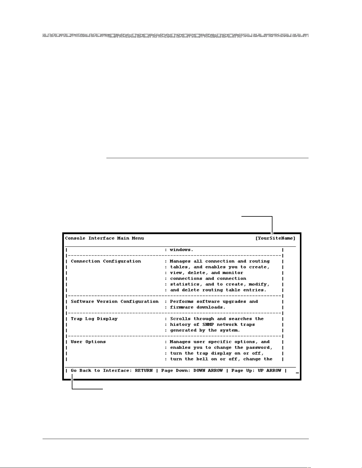
Chapter 1 Getting Started
Help Information
Help Information
The Help windows are accessible from any window in the PSAX system console interface. To access the Help windows, press the ? (Question Mark) key
on any window. In addition to the Help windows, the Console Interface windows display contextual help in the information line at the bottom of each
window. Contextual help provides information about the command or field
currently highlighted on that window. The information line also displays
error codes and responses to commands. All responses and notifications are
recorded in a trap log. See the PacketStar
Protocol (SNMP) Trap Reference Guide for details on displaying the trap log and
obtaining explanations of the trap messages.
To view the Help windows from the Console Interface Main Menu window ,
perform the following procedure.
Begin
1 On the window for which help is desired, press the ? (question mark)
®
PSAX Simple Network Management
key.
The Help window for the current console window is displayed (see
Figure 1-2).
Your site name appears here
after initial configuration
Information Line
Figure 1-2. Main Menu Help Window
2 To display the remaining Help windows for the current console window,
press the Down Arrow key.
PacketStar® PSAX Enhanced Router Module User Guide, Issue 1 Release 9.1.0
1-8 255-700-614
Page 31

3 To scroll backward through the Help windows for the current console
4 To exit Help and return to the current console window, press the Enter
End
Technical Support
If you experience a problem with the Enhanced Router module module,
refer to the Lucent Technologies Product Warranty Registration Information, which
accompanied your shipment, for instructions on obtaining support in your
area.
Before You Begin
Before you start configuring and using your new Enhanced Router module,
be sure you:
• Record your site-specific specifications such as the IP addresses you will
use, and the connections and interfaces you will need. Decide which user
names and passwords you will assign.
• Make sure you have IP connectivity to all PSAX devices to be managed
• Determine the numbering scheme for any in-band management connec-
tions you will be using
Chapter 1 Getting Started
Tech nical Support
window, press the Up Arrow key.
key.
Comments on This Guide
To comment on the PacketStar® PSAX Enhanced Router Module User Guide,
please complete the comment card at the following web address:
http://www.lucent-info.com/comments/
You can also email your comments to [email protected].
Include the following information:
Title: PacketStar
Release number: Release 9.1.0
Document number: 255-700-614
Issue number: Issue 1
Publication date: March 2004
PacketStar® PSAX Enhanced Router Module User Guide, Issue1 Release9.1.0
255-700-614 1-9
®
PSAX Enhance d R o ut er Module User Guide
Page 32

Chapter 1 Getting Started
Comments on This Guide
PacketStar® PSAX Enhanced Router Module User Guide, Issue 1 Release 9.1.0
1-10 255-700-614
Page 33

Functional Description
The Enhanced Router module is the premier IP routing platform for the
PacketStar PSAX Multiservice Media Gateway systems. In addition to supporting existing PSAX multiservice interworking capabilities, the module provides routing, aggregation, and adaptation capabilities, and supports SPVC
connection options.
The module parses traffic (using IP filtering) and aggregates the traffic back to
the network backbone routers and switches, or directly to data centers where
the hosting applications reside.
2 Module Description
FAIL
ACTIVE
ROUTER
Figure 2-1. Enhanced Router Module
Feature Summary
Basic Features
This section provides an overview of features available on the Enhanced
Router module. The module may be configured to operate in one of two
modes:
PacketStar® PSAX Enhanced Router Module User Guide, Issue1 Release9.1.0
255-700-614 2-1
Page 34

Chapter 2 Module Description
Feature Su mm ary
~ In Single-Instance mode, the module operates as a monolithic router.
This is the default mode of operation.
~ In Multi-Instance mode, a limited set of features will be supported on up
to eight individual routing instances (VPNs).
Note: The Multi-Instance mode is not supported on the Enhanced Router
Routing and ARP Features
• The module supports multi-service routing, particularly:
~ Static routing
~ Dynamic protocol-driven routing, such as RIP versions 1 and 2, includ-
ing:
• VLSM (RFC 1058)
• Authentication
• Multicasting
• The module supports variable length masks for static and RIP-based routes.
The masks must be bit contiguous from left to right and at least two host
bits must exist.
• The module routes IP among various interfaces, particularly:
~ IP over frame relay (RFC 2427)
~ IP over Ethernet (bridge) (RFC 2684)
~ IP over ATM (RFC 2684)
~ IP over PPP over HDLC (over N x DS0s over T1 or E1)
• The module supports up to 32,768 routes. The Enhanced Router IP Route
Table displays a maximum of 8,192 routes.
• The module supports class of service (in Single-Instance mode only).
• The module supports unnumbered interfaces on A TM, PPP, and frame relay
IP interfaces (in Single-Instance mode only) (similar to point-to-multipoint
capabilities by other vendors).
module in Release 9.1.0.
Note: If you want to use static or RIP-based routes with variable masks
with RIP, you should use RIP version 2. If you use RIP version 1
and also have interface or static IP routes with variable masks,
aggregation problems may result.
• Each defined IP interface supports ICMP (RFC 792), RIP, and PPP.
• DHCP relay is supported on IP interfaces configured for ATM, frame relay,
bridge, and HDLC. DHCP relay primary and secondary servers can be
assigned per IP./Cisco HDLC interface
Note: DHCP relay and PPP can only be configured in Single-Instance
mode.
• The Enhanced Router ARP Table and Enhanced Router IP Route Table
tables may be displayed for each VPN.
Note: It is recommended that you do not display routing tab les if the net-
work is known to be in a state of flux.
• The module can receive and respond to inverse ARP requests.
• The module supports ARP (RFC 2225).
PacketStar® PSAX Enhanced Router Module User Guide, Issue 1 Release 9.1.0
2-2 255-700-614
Page 35

VPN Features
Connection Features
Chapter 2 Module Description
Feature Summ ary
• The module supports inverse ARP over ATM and frame relay (receives and
responds to requests only).
• The module supports up to 2,048 IP interfaces, which can be statically
shared (scaled) across VPNs.
• The module supports up to eight independent IP VPNs (in Multi-Instance
mode).
• All VPNs support the ability to ping another network element residing in a
given VPN.
• All VPNs support the ability to persistently notify the NMS of fault conditions occurring within the VPN.
• The module supports connection statistics.
• Connections can be either PVC or SPVC.
• PSAX in-band management connections can be made through the module.
• The underlying connections associated with an IP interface can be bridge,
PPP over HDLC, Cisco HDLC, in-band, frame relay, or ATM.
Other Features
• The module also supports:
Maximum Capacities
The maximum capacities for the Enhanced Router module are as follows:
• IP interfaces:
• Routes configured without routing protocols: 10,240
• Routes configured with RIP: 2,560
• ARP entries: 2,048 (An example of an IP interface that may consume an
~ IP filtering
~ Interoperability with other basic routers.
~ A variety of statistics.
~ Recovery from a chassis reboot, CPU switchover, I/O module reboot, and
other fault conditions.
~ IP interfaces configured without routing protocols: 2,048
~ IP interfaces configured as RIP interfaces: 128
~ IP interfaces configured as PPP over HDLC interfaces
1
: 2,048
~ IP interfaces configured as unnumbered interfaces: 100
ARP entry is traffic containing bridged Ethernet PDUs.)
1
Not all 2,048 IP interfaces can have keep alives and RIP enabled.
PacketStar® PSAX Enhanced Router Module User Guide, Issue1 Release9.1.0
255-700-614 2-3
Page 36

Chapter 2 Module Description
Software Features
• SPVC connections: 100
Software Features
Traffic Flow
The Enhanced Router module is an edge device that borders an IP network
and an ATM core network. Ingress IP traffic (Figure 2-2) from a given interface is forwarded at the edge device. Ingress IP datagrams may be for warded
to other edge devices connected to the ATM core, or they may be forwarded
to another interface on the same edge device. Egress ATM traffic is reassembled into IP datagrams and is forwarded in the same manner as ingress IP
traffic. A key PSAX differentiator using the Enhanced Router module is its
ability to support service quality through the use of ATM service-level mapping.
Enterprise/Service
Provider
Ingress IP
Traffic
Enhanced Router Module
Ingress ATM
Traffic
Figure 2-2. Traffic Flow Description
IP
ATM
ATM Network
Operating Modes of the Enhanced Router Module Module
The Enhanced Router module may be configured from the ERM VPN Table
window to operate in one of two modes: Single-Instance or Multi-Instance.
• The Single-Instance mode allows only one VPN to be created on the module. In the Single-Instance mode, mapping of physical network size to the
module’s physical resources is greatly simplified.
• The Multi-Instance mode allows one or more VPNs to be created on the
module. When using the Enhanced Router module in the Multi-Instance
operating mode, you must understan d the physi cal network char acteris tics
to ensure that the module’s physical resources can support the desired
number of VPNs.
Egress IP
Traffic
Egress ATM
Traffic
PacketStar® PSAX Enhanced Router Module User Guide, Issue 1 Release 9.1.0
2-4 255-700-614
Page 37

Note: The Multi-Instance mode is not supported on the Enhanced Router
module in Release 9.1.0. Do not perform configurations with the
Enhanced Router module in Multi-Instance mode.
IP Application in the Multiservice Media Gateway
An IP interface cons ists o f an IP addres s and an IP netw ork mas k. To pass traffic, each IP interface must be associated with at least one traffic-bearing connection.
Each VPN will likely be associated with multiple IP interfaces and their corresponding connections. As IP datagrams arrive on a given IP interface, an IP
routing decision is made and the appropriate outgoing IP interface is determined. The IP datagram is then sent out on the selected IP interface.
Each VPN may be configured to run network routing protocols and may als o
have user-configured static routes. The resulting routing table and configuration is not shared with any other VPN.
Module Operation
Chapter 2 Module Description
Software Features
The Enhanced Router module is installed in any PSAX chassis slot intended
to contain an I/O or server module. If you are installing the module in a
newly installed PSAX chassis, be sure to follow your facility site plan for placing this module in the correct location in the chassis.
The Enhanced Router module does not interoperate with the discontinued
optical modules associated with AQueMan or Traffic Shaping:
• 1-Port OC-3c Single-Mode with AQueMan
• 1-Port OC-3c Multimode with AQueMan
• 1-Port OC-3c Single-Mode with Traffic Shaping
• 1-Port OC-3c Multimode with AQueMan
• 1-Port STM-1 Single-Mode with AQueMan
• 1-Port STM-1 Multimode with AQueMan
• 1-Port STM-1 Single-Mode with Traffic Shaping
• 1-Port STM-1 Multimode with AQueMan
The operating mode of an Enhanced Router module is stored in its non-volatile RAM; thus, it will always boot-up in that mode until the mode is explicitly changed. The mode of an Enhanced Router module cannot be changed if
it is inserted in a slot that has an existing IP VPN configuration. To change the
operating mode, the module must be placed in a slot with no existing VPN
configurations; or, any existing VPN configuration must first be deleted.
Changing the mode of a module will cause the module to reboot.
The operating mode of an Enhanced Router module will automatically be
changed as determined by the existing VPN configuration for a given slot. For
example, if an Enhanced Router module is placed in a slot that is configured
with VPNs in the Multi-Instance mode, the PSAX system software will set the
PacketStar® PSAX Enhanced Router Module User Guide, Issue1 Release9.1.0
255-700-614 2-5
Page 38

Chapter 2 Module Description
Software Features
Enhanced Router module mode to match existing slot configuration. As
such, when an Enhanced Router module is inserted, if necessary, it may
immediately reboot as it switches operating modes.
Note: The Multi-Instance mode is not supported on the Enhanced Router
module in Release 9.1.0. Do not perform configurations with the
Enhanced Router module in Multi-Instance mode.
To change the operating mode on the Enhanced Router module, see
Chapter 3.
Enhanced Router Database Conversion
In Release 9.1.0, the Enhanced Router module suppor ts the Enhanced
Router Database Conversion feature. This feature allows the database and
configuration files of a Release 8.1.5 or Release 9.0.0 Enhanced Router module to be preserved after a CPU upgrade to Release 9.1.0. However, DHCP
configurations made in Multi-Instance mode are not supported by this feature.
Enhanced Router-to-ATM OAM Interworking
OAM support is provided by bidirectional in-band F4 and F5 OAM cells flowing at the ATM layer for the VPC and VCC levels, respectively. Where a service provider chooses to use F4 and F5 OAM, they can operate and maintain
the physical layer and the ATM layer aspects of broadband networks, regulating permanent, semipermanent, and switched virtual circuits. Following the
same physical and logical route as the user payload cells, these cells are used
primarily to monitor and manage faults and performance, and to check continuity.
Enhanced Router-to-ATM Interworking complies with ITU-T I.610 requirements for the ATM connection to the Enhanced Router module. The traff ic
carried in this connection is Bridge-to-ATM VCC PVC. The OAM procedures
supported include continuity check, loop back, and AIS/RDI.
Enhanced Router-to-ATM Interworking is enabled when an ATM interface is
virtually connected to the Enhanced Router module. When the Enhanced
Router module receives OAM AIS or RDI cells, the associated connection will
be taken out of service. When failure recovers, the Enhanced Route r connection will come back into service. These changes will be reflected in the routing tables.
Class of Service
The class of service (CoS) feature allows the Enhanced Router module to
queue packets differently based on the following classification schemes:
DSCP (diffserv), subchannel, and fixed. The supported classification schemes
in Release 9.1.0 are fixed, subchannel, and DSCP. This feature is supported
on bridge and ATM (PVC only) IP interfaces.
PacketStar® PSAX Enhanced Router Module User Guide, Issue 1 Release 9.1.0
2-6 255-700-614
Page 39

Chapter 2 Module Description
Software Features
Classification is done on the ingress, and is specified at the connection level.
Each connection in an IP interface is configu red with the r ange of C oS values
that it supports. For example, VCC 1= CoS 1–3, VCC 2= CoS 4–5, VCC 3=
CoS 6. After the classification process, an IP packet is assigned a single CoS
value. The IP packet is ready to be forwarded.
Capacity of
Up to 16 classification tables may be created per VPN.
Classification Tables
DSCP (Diffserv)
Classification
In the DSCP classifi cation scheme, p ackets are cl assified based on the va lue of
the DSCP bits in the IP he ader. You can specify whi ch DiffS erv mappi ng table
to use on the Enhanced Router Class Rule Table window to map six bits in
DiffServ to a CoS value of 1–6.
Subchannel Classification
In the subchannel classification scheme, packets are classified based on the
incoming connection (also known as a subchann el) of an A TM or frame relay
IP interface. The connection corresponds to a Connection ID on an ATM or
frame relay IP interface. This classification is only supported when the adjacent router is another PSAX system.
Fixed Classification In the fixed classification scheme, all packets arriving on an IP interface are
assigned the color specified on the Enhanced Router IP Interface Configuration window.
For fixed classification, the information is tied to the interface and a fixed
color value is given to the IP interface. All packets arriving to that interface
are given the same color. For subchannel and DSCP classification schemes,
you must create a classification table. See Table 2-1.
Table 2-1. Differentiation Between Enhanced Router Classification
Schemes
If the classification
scheme is...
then this is how to impl ement
it...
DSCP assign a classification table ID (table)
Subchannel assign a classification table ID (table)
Fixed use a fixed classification parameter
(no table)
IP Interface and Connection Operations
When an IP interface is brought into service, it should be able to carry traffic
of all colors. If not, the interface will not be operationally brought into service. For example, if a connection in an interface is configured to carry traffic
of colors 1,2, and 3, then the i nte rfa c e will no t be bro ug ht i nto ser vic e . More
connections should be created such that they can all carry traffic of colors 4,
5, and 6.
Note: Two connections cannot carry traffic of same color.
If any of the connections go down, the interface is either operationally taken
out of service until it is restored, or torn down and another one created so
that it fulfills the above conditions. To change any of the classification parameters, the existing IP interface should be deleted and a new interface with
new classification parameter values should be created.
PacketStar® PSAX Enhanced Router Module User Guide, Issue1 Release9.1.0
255-700-614 2-7
Page 40
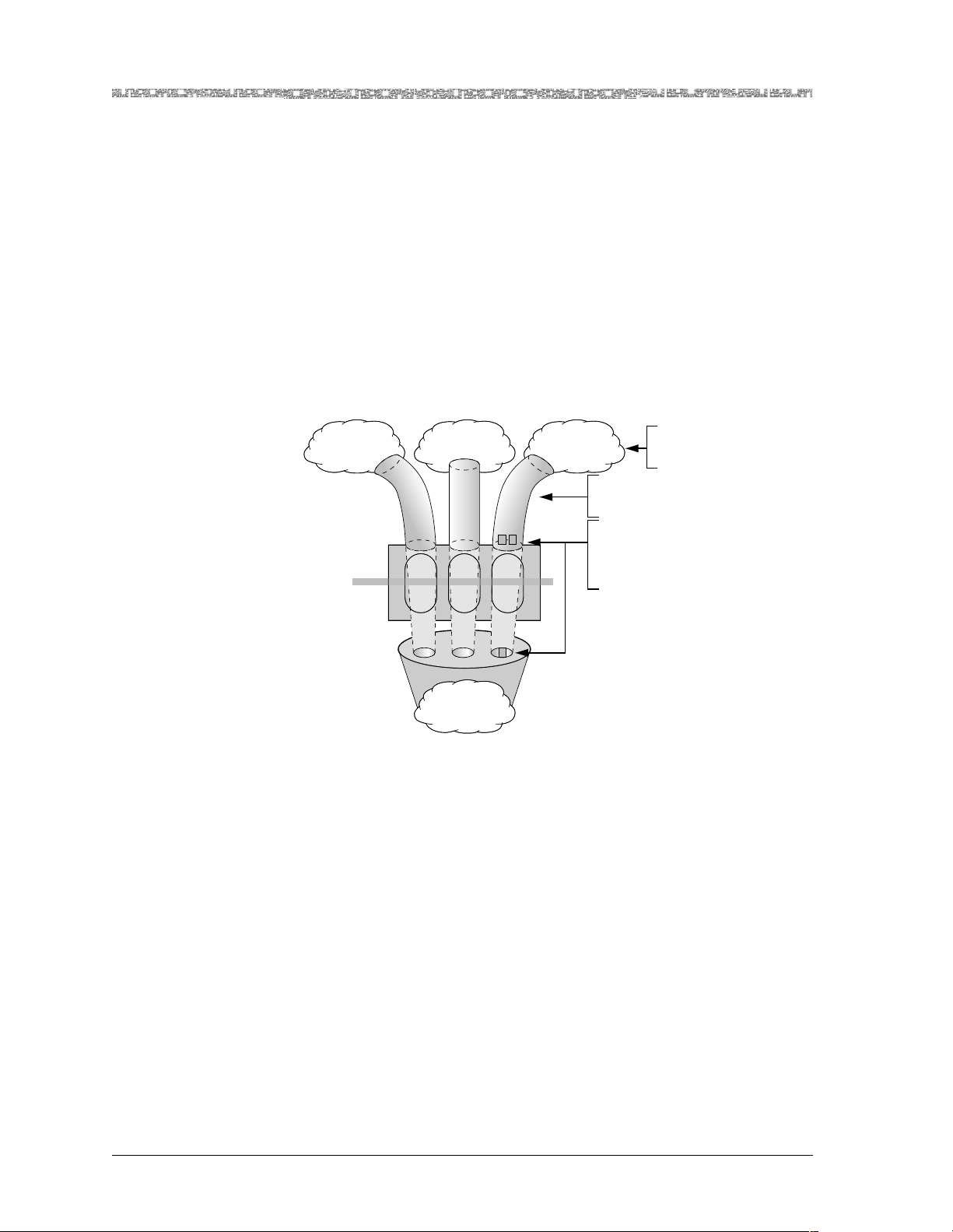
Chapter 2 Module Description
Software Features
Ingress DiffServ Mapping Table
Virtual Routing
The six bits in DiffServ are mapped into CoS values of 1–6.
Another key differentiator using the Enhanced Router mo dule in Multi-VPN
mode is the virtual router aspect of the module (see Figure 2-3). The virtual
routing capability arises from its ability to form groupings of IP interfaces that
can combine to act a s separa te IP netw orks relati ve to so me other gr ouping of
IP interfaces on the same device. An IP interface may be defined in a variety
of ways, depending upon physical interface type. Each grouping of IP interfaces that belongs to a user will behave as the interfaces belonging to a standard IP router. The IP addresses assigned to th e IP interfaces (as well as the
underlying IP traffic through each module) may have overlapping address
space without the concern of crosstalk from one VPN to the next.
Enterprise 1/
Service Provider 1
Ingress/Egress
IP T raffic
dge Device
Ingress/Egress
A TM Traffic
Enterprise 2/
Service Provider 2
R
R
O
O
U
U
T
T
I
I
N
N
G
G
Enterprise 3/
Service Provider 3
R
O
U
T
I
N
G
The Enterprise/Service Provider
consist of one or more
physical connections.
Interfaces are assigned through
configuration mechanisms
and may be logical or
physical entities.
Each Enterprise/Service Provider
occupies its own
virtual router space.
ATM Network
Figure 2-3. Virtual Router Concept
The module supports IP over ATM virtual routing in conjunction with the
other PSAX I/O modules. Y ou can co nfigure a virtual r outer at the module t o
communicate with the management router at the CPUn module. As the
default gateway for the CPUn module, the module can handle all the in-band
management traffic.
Virtual router concepts, network interface assignment, and the relationship
between the existing I/O modules and the Enhanced Router module are
shown in Figure 2-4.
PacketStar® PSAX Enhanced Router Module User Guide, Issue 1 Release 9.1.0
2-8 255-700-614
Page 41
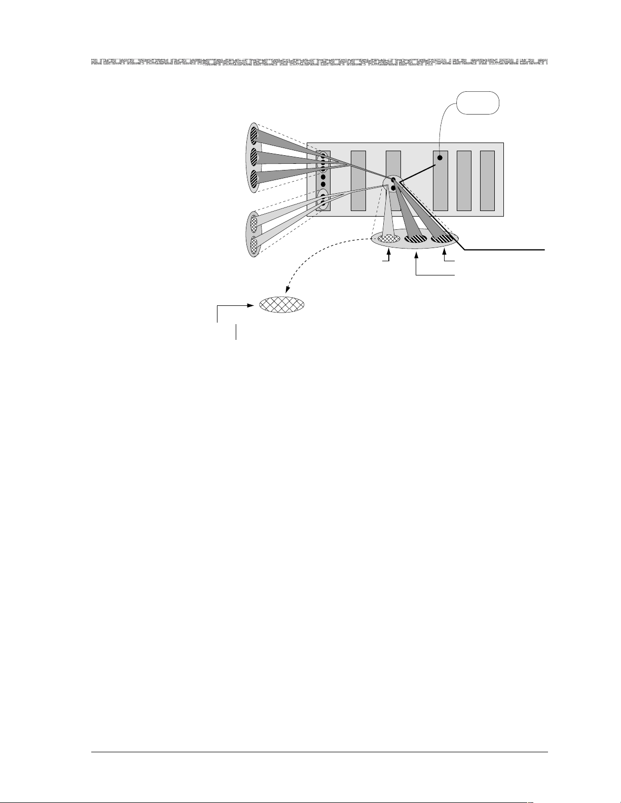
Chapter 2 Module Description
Software Features
FR Connections Partitioned
into Interfaces
192.001.001.001
255.255.255.000
Virtual
192.001.002.001
Router
255.255.255.000
#1
192.001.003.001
255.255.255.000
145.121.215.001
Virtual
255.255.000.000
Router
#2
145.122.215.001
255.255.000.000
An IP interface can be
assigned a VC that
corresponds to any
ATM class of service.
145.123.215.001
255.255.000.000
Figure 2-4. Enhanced Router and Example Configuration
Unnumbered Interfaces
Gold
Silver
Bronze
E
R
M
O
D
U
L
E
145.123.215.001
255.255.000.000
ATM Connections Partitioned
into Interfaces
ATMFR
Existing
In-Band
Management
C
P
U
Console
S
P
T
R
O
A
W
T
E
U
M
R
Existing In-Band Management
192.001.004.001
255.255.255.000
192.001.005.001
255.255.255.000
The Unnumbered Interfaces feature (see Figure 2-5) supports point-to-multipoint configurations often used in routing over frame relay and ATM networks.
This allows one IP address to be assigned to the physical interface or router
with multiple virtual circuits, without having to number each virtual circuit
individually. This feature is configurable from the Enhanced Router IP Interface Configuration window. RIP and static routes are supported on unnum-
PacketStar® PSAX Enhanced Router Module User Guide, Issue1 Release9.1.0
255-700-614 2-9
Page 42
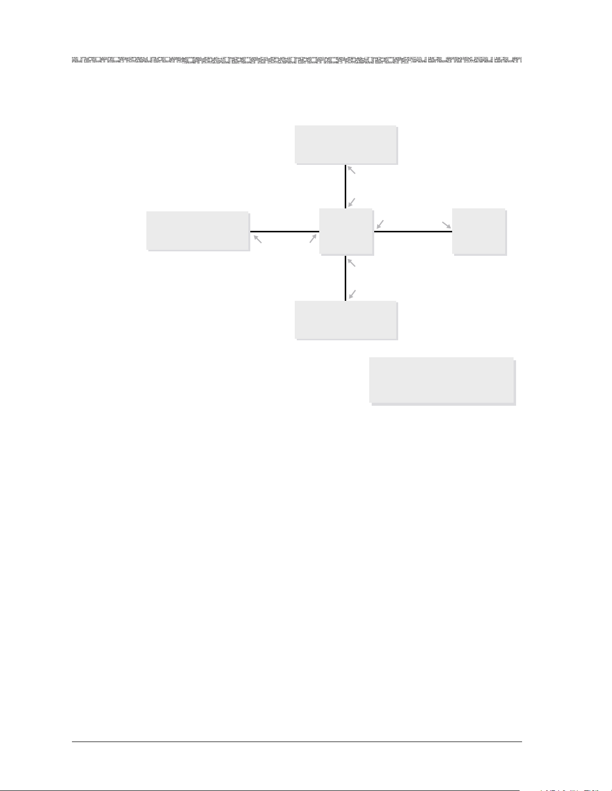
Chapter 2 Module Description
Software Features
bered interfaces. The feature works when static routes are used without a
routing protocol (such as RIP) are used. Unnumbered interfaces are not supported on Ethernet interfaces.
Router C
20.1.1.2
20.1.1.1
10.1.1.2
VPN 2VPN 1
Router B
10.1.1.4
10.1.1.1
(unnumbered
interface)
10.1.1.1
10.1.1.1 (unnumbered interface)
10.1.1.3
Router A
Legend:
VPNs 1 and 2 are on the Enhanced Router module,
Routers A, B, and C can be an Enhanced Router
module or another type of router.
Figure 2-5. Unnumbered Interfaces Example
When an unnumbered interface is created, it becomes the router ID, and is
treated as a logical int erface. A second unnumb ered interface is a utomatically
created as a subset of this router ID. Subsequent unnumbered interfaces can
be created for this router ID by using the same IP address as the router ID,
and a different neighbor IP address for each unnumbered interface.
All IP interfaces that have the same IP interface address (or router ID) belong
to the same unnumbered interface group. For unnumbered interfaces, only
the class-based mask is allowed.
The peer IP address is allowed to be on a different subnet than the local IP
address. For unnumbered interfaces, the RI P interface table will display the
IP address in the form 0.0.0.n where n is a 16-bit integer specifying the interface index of that unnumbered interface.
All IP interfaces using the same unnumbered interface group will have the
same IP Interface Addr value but the Neighbor IpAddr values will be different. DHCP Relay and class of service features are not supported on unnumbered interfaces. Unnumbered interfaces are only supported in ATM and
frame relay connections.
PacketStar® PSAX Enhanced Router Module User Guide, Issue 1 Release 9.1.0
2-10 255-700-614
Page 43

RIP Version 2 Features
RIP version 2 adds additional functionality to RIP version 1, such as external
route tags, subnet masks, next hop router addresses, authentication, and
multicasting.
Note: RIP is intended to operate as an interior gateway protocol within a
RIP version 2 allows you to divide networks to a further extent than the traditional subnet classes (Class A, B, and C) with RIP version 1. It also allows
you to run different masks on different subnets, which is not possible when
you use RIP version 1. RIP version 2 also enables the use of authentication
and multicasting.
Note: If you want to use static or interface routes with variable masks by
Chapter 2 Module Description
Software Features
relatively small network with a longest path of 15 hops. RIP uses
fixed metrics to compare alte rnative routes . It is not appropriate for
situations where routes need to be chosen based on real-time
parameters such a measured delay, reliability, or load. The obvious
extensions to allow metrics of this type are likely to introduce
instabilities that the protocol is not designed to handle.
way of RIP, you should use RIP version 2. If you use RIP version 1
and also have interface or static routes with variable masks, aggregation problems may result.
Authentication Optionally, you can assign an authentication password to an IP interface for
maximum security. An authentication password is essential to prevent those
who cannot directly access the networ k f rom sending b ogus routing information into the routers. The password must be ASCII text.
If the router is not configured to authenticate RIP version 2 messages, then
RIP version 1 and unauthenticated RIP version 2 messages will be accepted,
and authenticated RIP version 2 messages will be discarded. RIP version 1
messages will be ignored when authentication is in use. However, authentication does not prevent RIP version 1 routers from seeing RIP version 2 messages. To prevent other RIP version 1 routers from seeing RIP version 2 messages, you must use multicasting.
Multicasting Multicasting reduces load on hosts not using RIP version 2 messages. Multi-
casting also allows RIP version 2 routers to share information that RIP version 1 routers cannot access.
Address Resolution Protocol (ARP)
ARP is a TCP/IP protocol used to map an IP address into a physical Ethernet
MAC address. A host wishing to obtain a physical address broadcasts an ARP
request onto the TCP/IP network. The host on the network that has the IP
address in the request then replies with its physical hardware address.
Reverse ARP (RARP) can be used by a host to discover its IP address. In this
case, the host broadcasts its physical address and a RARP server replies with
the host’s IP address.
PacketStar® PSAX Enhanced Router Module User Guide, Issue1 Release9.1.0
255-700-614 2-11
Page 44

Chapter 2 Module Description
Software Features
ARP functionality is supported for all interface types that are configured to
carry bridged Ethernet traffic. You may specify a MAC address or allow a
MAC address to be randomly selected from an available pool pre-programmed into the Enhanced Router module.
Inverse ARP is similar to ARP, but is used to map IP addresses to ATM end
addresses. ATM interfaces associated with the Enhanced Router module will
respond to inverse ARP requests.
Static Routing
Static IP Routing Overview
Static routing provides a means of explicitly defining the next hop from a
router for a particular destination. A router that supports a dynamic routing
protocol must allow static IP routes to be defined with any metric valid for
the routing protocol used. You can specify whether or not to redistribute all
static IP routes on the module by enabling the RIP Redistribute Static field on
the Enhanced Router VPN Configuration window.
In the typical case, the destination of a static route can be either a network or
a host address. A default route can be created by setting the destination and
mask to zero.
Static IP routes are associated with a specific IP interface and a specific service
type belonging to that interface. Thus, before a static route can be defined,
the intended IP interface and connection must first exist. When specifying a
static route, the user must provide the destination IP address and netmask.
The destination address and mask may be 0.0.0.0 which effectively defines a
default route. If the destination is not 0.0.0.0, strict address checking is performed. You can configure static IP routes with duplicate destination address
or mask pairs and service types: as long as the next hop values and metric
values are different, two static IP routes to the same destination address or
destination mask can be configured. The route with the lowest cost will be
displayed in the Enhanced Router IP Route Table window. If the lower-cost
route is removed due to deletion or a link failure, the higher-cost route will
replace the lower- cost route in the Enhanced Router IP Route Table window.
Yo u must specify a gateway address on the Enhanced Router IP Route Table
window. The gateway address must be a remote address on the same network as the IP interface or the IP interface address (for interface-routing
capabilities).
Static IP routes are not dynamic, so it is recommended that you only use
static IP routes for routers that do not use RIP, or for routers that use RIP but
do not have an authentication password assigned to them. Otherwise, you
may have to manually edit the static route according to changes in your network configuration. RIP routes will dynamically change according to changes
in the network, without manual intervention.
IP Route Table The Enhanced Router IP Route Table window contains lists of internet
addresses and their corresponding locations in the network, and displays the
routes that have been learned from advertisements received through VPNs,
or entered by applying static IP routes. This information can be used when
troubleshooting routing problems.
PacketStar® PSAX Enhanced Router Module User Guide, Issue 1 Release 9.1.0
2-12 255-700-614
Page 45
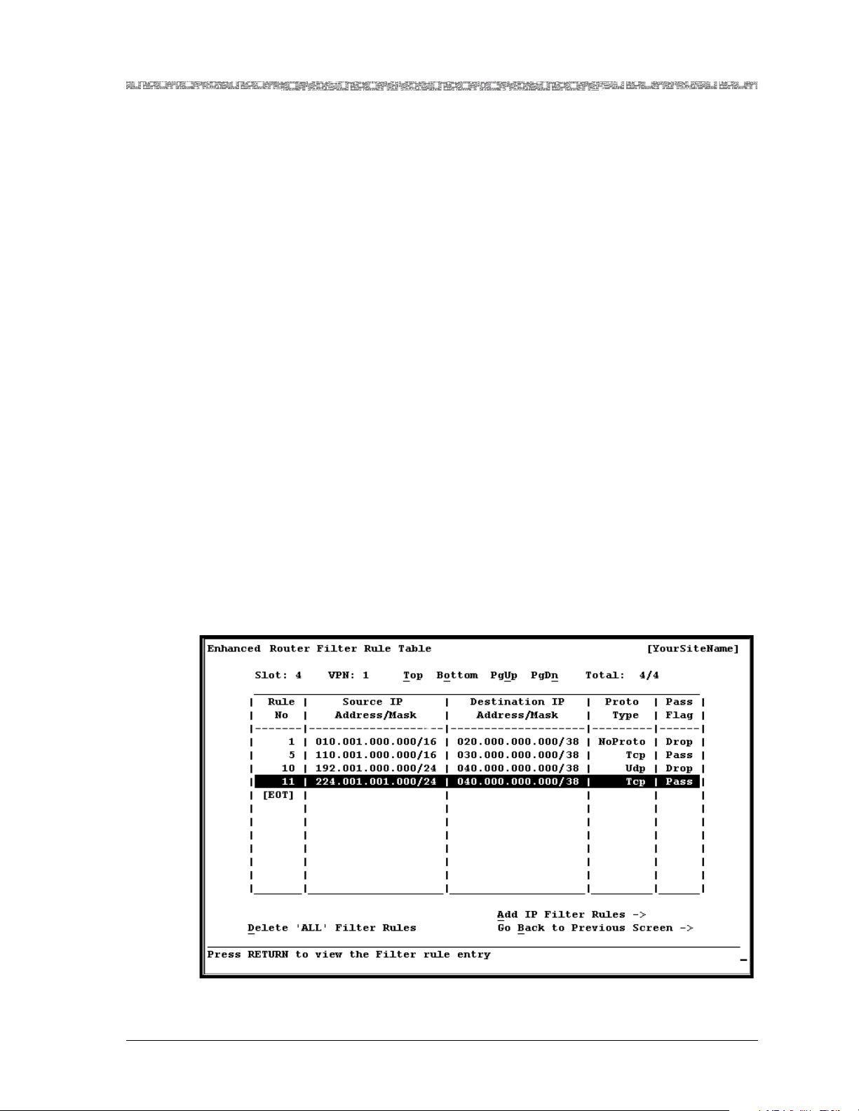
IP Filtering
Chapter 2 Module Description
Software Features
A router connected to a network must be able to identify which interface is
to be used to reach every other connected end system. Routers near the center of a network generally have very large routing tables, those near the
edges have smaller tables. The destination IP address will be used to route the
packet out to the appropriate connection.
Routing lookups are based on longest mat ch on the ma sk. Host routes have a
mask of all 1s, and therefore have priority over all other routes. Otherwise,
no other route type (static, interface, RIP) takes precedence over another.
The displayed output of the Enhanced Router IP Route Table window does
not infer any internal organizational structure within the internal memory of
the module.
IP Filtering on the Enhanced Router module module involves a packet filter
that contains rules describing packets, and actions to take on those packets
that match the description of the filter. Filter rules cause the module to take
an action (such as forward or drop) on the packets that match the rules. The
packets come from the network, are processed by the module, and then, if
the packet is determined to be passed, sent out of the module to the correct
interface. Packets that are dropped due to filtering are dropped silently.
IP Filtering works by dropping or passing packets per the rules you set on the
Enhanced Router Filter Rule Configuration window (for instructions and
field descriptions, see Chapter 3 if using the console, or Chapter 5 if using the
AQueView EMS). The value in the Filter Rule Id field indicates the priority of
the filter rules (that is, the order in which the rules will be processed). The
lower the rule number, the higher the priority for processing. Refer to
Figure 2-6 for this discussion.
Figure 2-6. Sample of Filter Rules Configured on an Enhanced Router Module
PacketStar® PSAX Enhanced Router Module User Guide, Issue1 Release9.1.0
255-700-614 2-13
Page 46

Chapter 2 Module Description
Enhanced Router Module Applications
In the example shown in Figure 2-6, if a packet matches Rule 1, then it is
dropped. The Enhanced Router module module will not check any other
rules in this case, because Rule 1 matched the packet.
If a packet does not match Rule 1, then the module checks Rule 5. If a packet
matches Rule 5, the packet is passed. The module will not check any other
rules, even if Rule 10 may have also matched the packet (in the case of Rule
10, the module would drop the packet).
If neither Rule 1 nor 5 matched the packet, the module checks Rule 10. Likewise all rules are checked, and if no rules are matched, the packet is passed.
The default rule will always be the last rule to be applied when none of the
preceding rules is ever matched.
If you want a default action of Drop, insert a rule with a maximum value in
the Filter Rule Id field (for example, 65535), change all the numeric field values on the Enhanced Router Filter Rule Configuration window to their
default values, and set the Filter Pass Flag field to Drop. This configuration
will ensure that the default rule is to drop the packet. If you want the default
rule to pass the packet, select the value Pass.
Enhanced Router Module Applications
1xEVDO Applications
Release 9.1.0 of the Enhanced Router module introduces the 1xEVDO over
ATM application (not to be confused with the 1xEVDO application that was
introduced in Release 8.1.5). This application provides a scalable wireless hub
solution that includes layer 2 aggregation of 1xEVDO interfaces without
routing. The PSAX system can be use d in the 1xEVD O appli cation wi th a basestation or any router that works with Cisco HDLC encapsulation.
T o enable the 1xEVDO app lication, you must co nfigure an HDL C connect ion
and specify HDLC in the Traffic Type field (see Chapters 4 and 6). To enable
the 1xEVDO over ATM application, you must configure an ATM connection
and specify HDLC in the Traffic Type field (see Chapters 4 and 6). The
1xEVDO applications are not supported when RIP, OSPF, unnumbered interfaces, or class of service is enabled on an IP interface.
Figure 2-7 displays a 1xEVDO backhaul application with a PSAX 4500 or
PSAX 2300 system installed with 24-Port High-Density DS1 and 21-Port
High-Density E1 modules. Routing is done using static routes. This application has the ability to configure up to 64 DHCP servers addresses in the
Enhanced Router module. Each IP interface can be associated with its own
primary and backup DHCP servers.
For information on provisioning the 1xEVDO application, see the Provisioning
of the PSAX for User as an Aggregation Router for 1xEV-DO Application Note on
your PacketStar PSAX Multiservice Media Gateways, Product Information
Library CD-ROM.
PacketStar® PSAX Enhanced Router Module User Guide, Issue 1 Release 9.1.0
2-14 255-700-614
Page 47
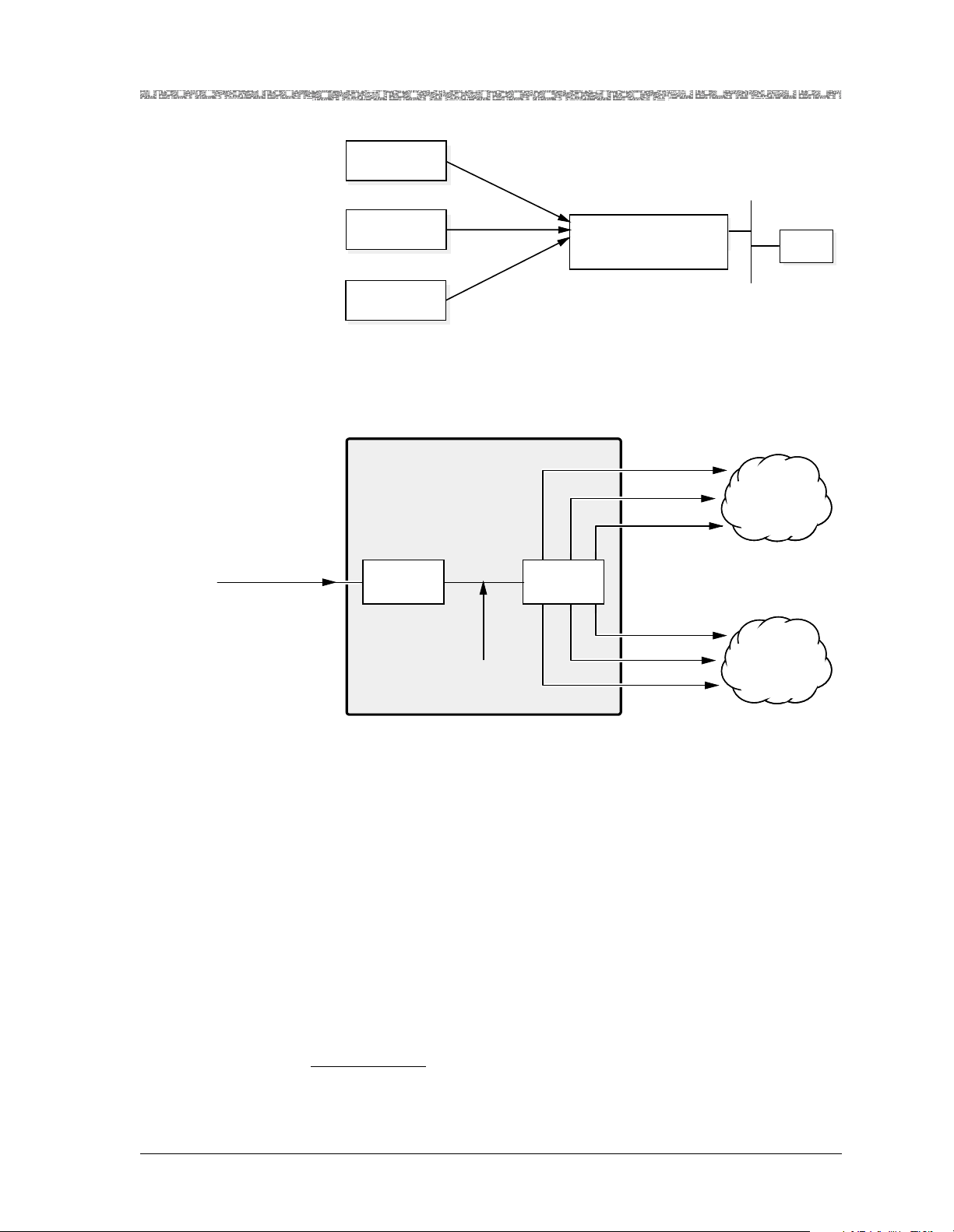
1xEVDO
Base Station
Chapter 2 Module Description
Enhanced Router Module Applications
Figure 2-7. 1xEVDO Backhaul Application
QoS Transport Application
In Figure 2-8, IP packets are transported by ATM VCC connections.
DiffServe
Masked IP Packet
1xEVDO
Base Station
1xEVDO
Base Station
Enhanced
Router Module
Hardware
Classifier
6 Classes of Service
PSAX 4500/2300 with
Enhanced Router Module
Forwarding
Engine
VBR-RT
VBR-nRT
UBR
Gold LSP
Silver LSP
Bronze LSP
RNC
IP over Ethernet
ATM
Core Network
IP over MPLS
Network
Figure 2-8. Enhanced Router Module QoS IP Transport Application
In Figure 2-9, the PSAX 1000 or PSAX 4500 system installed with the
Enhanced Router module provides QoS transport for V oIP traffic. This IP PBX
backhaul with QoS transport application is used primarily in regional or global call centers
2
When the PBX is a VoIP PBX and while running both voice and data on the same
ATM trunk.
PacketStar® PSAX Enhanced Router Module User Guide, Issue1 Release9.1.0
255-700-614 2-15
2
.
Page 48

Chapter 2 Module Description
Hardware Fe atures
IP PBX
IP PBX
PSAX 1000 with
Enhanced Router
Module
PSAX 1000 with
Enhanced Router
Module
Figure 2-9. IP PBX Backhaul with QoS Transport Application
Hardware Features
The Enhanced Router module has the following hardware features:
• IP forwarding performance of 540 Mbps simplex cell bandwidth at
64 bytes, IP packets
• User throughput: 135 Mbps bidirectional forwarding 60-byte packets
• Maximum frame size, including the header:
~ ATM: 9,180 bytes
~ Frame relay: 1,500 bytes
~ Ethernet: 1,500 bytes
~ PPP over HDLC: 1,500 bytes
~ Cisco HDLC: 1,500 bytes
ATM
Network
PSAX 4500 with
Enhanced Router
Module
IP PBX
Hardware Specifications
Table 2-2 provides the general physical hardware and environmental specifications for the PacketStar PSAX I/O and server modules.
Table 2-2. Physical Hardware Specifications
Specification Description
Dimensions 17.3 cm H x 2.41 cm W x 24.1 cm D
Weight 0.34 kg (0.76 lb.)
Operating temperature range for all the
PSAX 1250, PSAX 2300, and
PSAX 4500 systems
Operating temperature range for the
PSAX 1000 systems
Operating humidity range for all chassis
(6.8 in. H x 0.95 in. W x 9.5 in. D)
0° to 50° C (32° to 122° F)
For AC-powered PSAX 1000 systems:
0° to 50° C (32° to 122° F)
For DC-powered PSAX 1000 systems:
-20° to 60° C (-4° to 140° F) with a cold start minimum of
0° C (32° F)
5% to 85% relative humidity
PacketStar® PSAX Enhanced Router Module User Guide, Issue 1 Release 9.1.0
2-16 255-700-614
Page 49

Table 2-2. Physical Hardware Specifications (Continued)
Specification Description
Operating altitu de range for all chassis
60 meters (197 feet) below sea level to 4,000 meters
(13,123 feet) above sea level
Chapter 2 Module Description
Hardware Fe atures
Storage temperature range for all
-40° to 70° C (-40° to 158° F)
chassis
Storage humidity range for all chassis
0% to 90% noncondensing
Performance and Power Specifications
Table 2-3 provides the chassis speed, power consumption, and memory allocation specifications for this module.
Table 2-3. Performance and Power Specifications for the Enhanced Router Module Module
Total
Module
Enhanced Router
*
This column relates only to the speed at which the module communicates within the c hassis. A high-speed
module will communicate at high speed (1.2 Gbps) in a chassis that has a high-speed bus (PSAX 4500
chassis). High-speed modules will commun icate a t 600 Mbps in any other chassis. Low-spe ed modul es will
always communicate at 600 Mbps in any chassis.
†
The SDRAM listed only takes into account the memory associated with the upper layer processor. It does
not take into account the fastpath processor (firmware) or the hardware reassembly buffers.
Amount of
SDRAM
512 MB
Module
Program and
Data Space
†
490 MB N/A N/A High
Maximum
Input
Buffer
Output
Buffer
Chassis
Speed
Speed
*
Maximum
Power
Consumption
18 W
LED Indicators
Table 2-4 describes how the light-emitting diode (LED) indicators on the
Enhanced Router module faceplate respond to different module conditions.
These LEDs indicate if the module has been installed properly.
PacketStar® PSAX Enhanced Router Module User Guide, Issue1 Release9.1.0
255-700-614 2-17
Page 50

Chapter 2 Module Description
Hardware Fe atures
Table 2-4. LED Indicators for the Enhanced Router Module
FAIL (red) Initial
ACTIVE
(green)
Module Status
LED
Lights
Briefly
power-on
Initial
power-on
*
Not lit Lights
Module is functioning properly
No configured
VPNs
Module is not functioning
properly
Module is functioning
properly and a VPN is
configured
*
After power is initially applied to the system and the sy stem boot is complete, the FAIL and ACTIVE LEDs indicate whether the module has no
configured VPNs (no LEDs lit), one or more configured VPNs (green), or
is malfunctioning (red).
PacketStar® PSAX Enhanced Router Module User Guide, Issue 1 Release 9.1.0
2-18 255-700-614
Page 51

3 Configuring VPNs Using the Console
Interface
Overview of This Chapter
This chapter describes how to do the following:
~ Configure various components of the Enhanced Router module:
• VPNs
• IP interfaces
• IP filter rules
• static IP route s
• ARP
• class of service parameters
~ View various display-only components of the Enhanced Router module:
• ICMP statistics
• IP interface statistics
• RIP interfaces
• IP addresses
~ And how to:
• Change the operating mode of the module
• Save your configuration
Before You Begin
Be sure you have done the following first before beginning configuration of
the Enhanced Router module:
• Set the values to configure your basic system (see the appropriate Packet-
®
PSAX Multiservice Media Gateway User Guide)
Star
• Set the values to configure the Stratum 3–4 module (see the appropriate
PacketStar
• Set the values to configure the appropriate I/O modules (see the appropriate PacketStar
To configure the Enhanced Router module, you must configure the VPNs, IP
interfaces, and connections.
®
PSAX Multiservice Media Gateway User Guide)
®
PSAX module user guides)
Configuring the Module
You must first configure the Enhanced Router module before you can s et up
connections that use the features of the module. Before configuring a VPN,
the appropriate physical I/O interfaces must first be configured through the
corresponding menu beginning from the Equipment Configuration window.
PacketStar® PSAX Enhanced Router Module User Guide, Issue1 Release9.1.0
255-700-614 3-1
Page 52
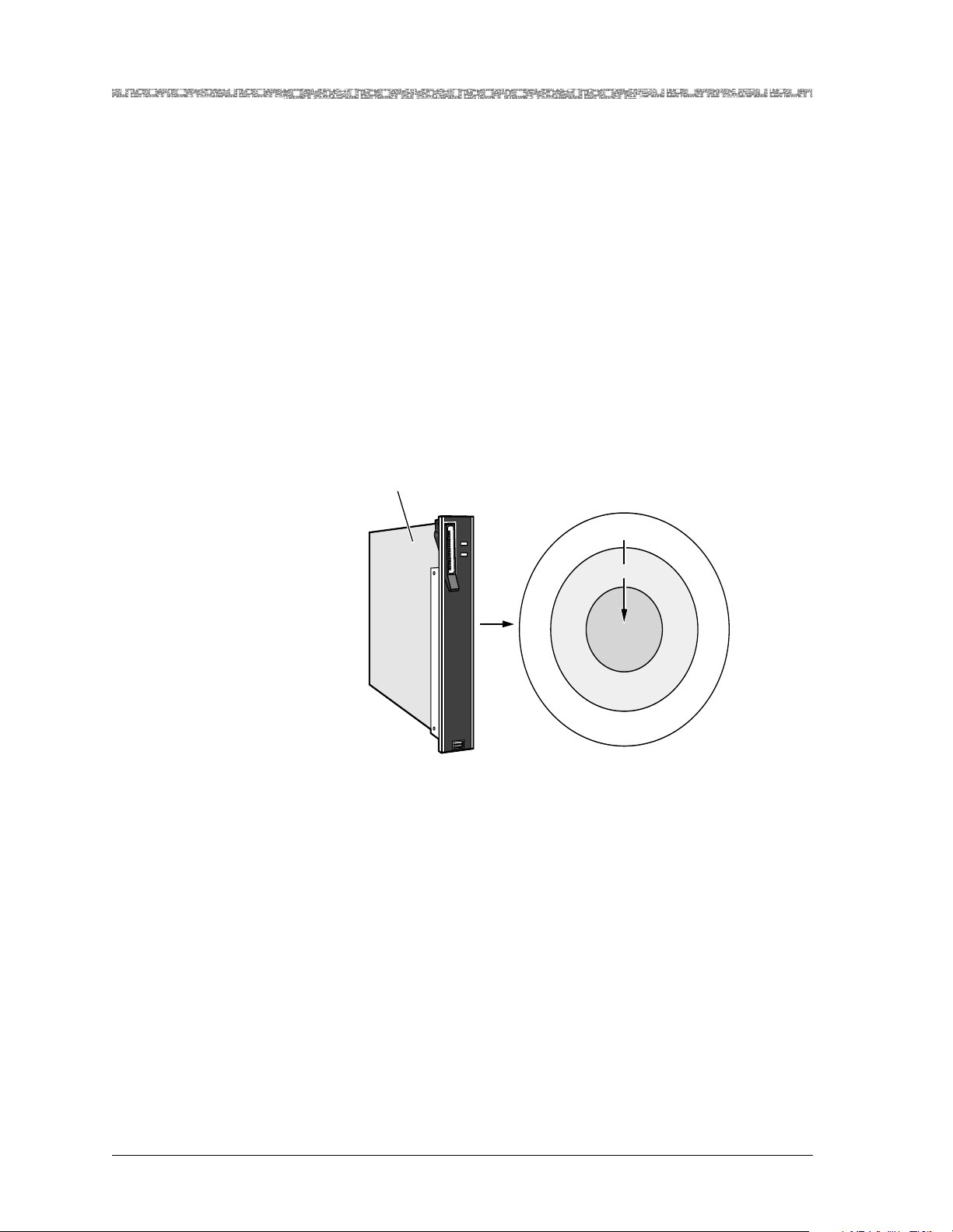
Chapter 3 Configuring VPNs Using the Console Interface
Configuring the Module
Hierarchy of the Enhanced Router Configuration
You must configure the Enhanced Router module in a hierarchy of three
major tasks (see Figure 3-1):
1. Configure a VPN (see ”Configuring VPNs” on page 3-5).
2. Configure IP interfaces within the given VPN (see ”Configuring IP Interfaces” on page 3-19).
Note: The interface numbers you choose in step 2 may be repeated when
configuring the other VPNs, but the interface number must be
unique within the VPN that it is configured. The Enhanced Router
module does not allow two interfaces on the same VPN to exist on
the same subnetwork.
3. Configure connections within the given interface (see Chapter 4).
Note: The connection numbers you choose in step 3 may be repeated
when configuring the subsequent VPNs (and the corresponding
interfaces within them).
Enhanced Router
Figure 3-1. Hierarchy of VPN Configuration
Note: In addition to assigning interfaces, you may define static IP routes
(see “Configuring Static IP Routes” on page 3-46).
Accessing the VPN Configuration Table
To access the Enhanced Router VPN Table, perform the following procedure.
t
n
e
c
u
L
FAIL
X
X
X
X
X
X
ACTIVE
X
X
X
X
X
ROUTER
VPN
Interface
Connection
PacketStar® PSAX Enhanced Router Module User Guide, Issue 1 Release 9.1.0
3-2 255-700-614
Page 53
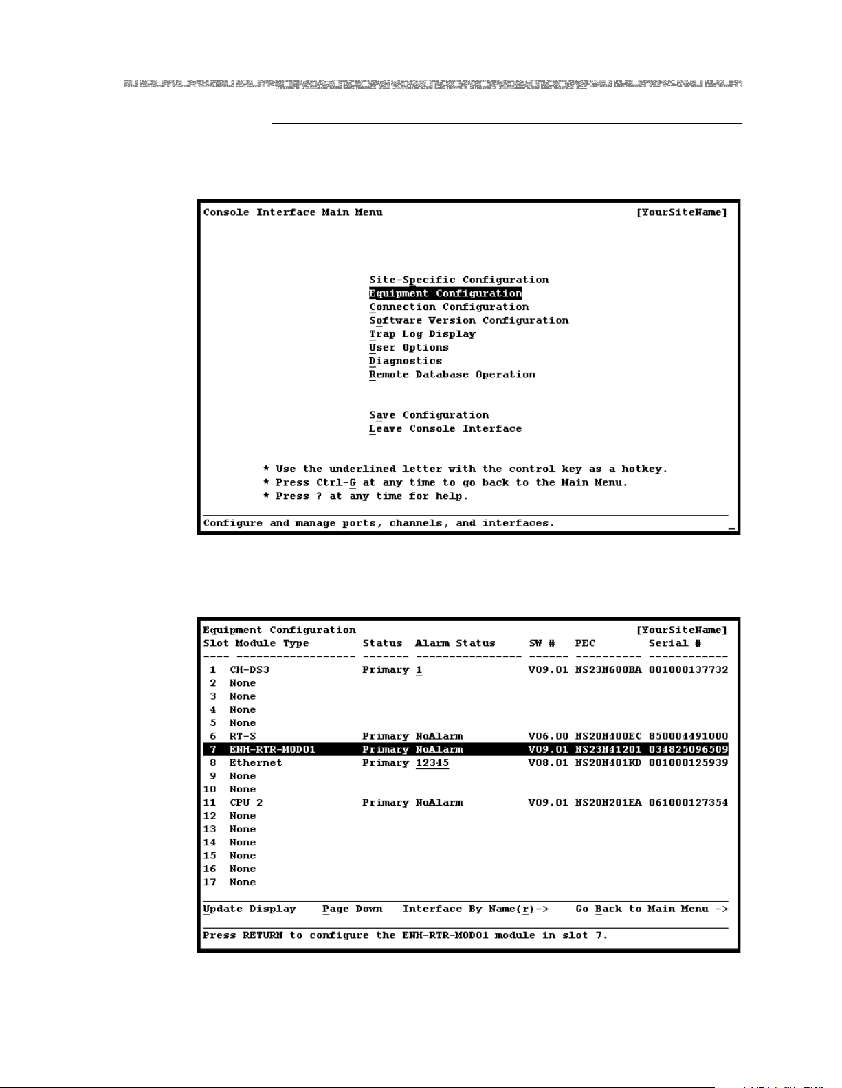
Chapter 3 Configuring VPNs Using the Console Interface
Configuring the Module
Begin
1 On the Console Interface Main Menu window ( see Figure 3-2), select the
Equipment Configuration option.
Figure 3-2. Console Interface Main Menu (Equipment Configuration Selected)
The Equipment Configuration window is displayed (see Figure 3-3).
Figure 3-3. Equipment Configuration Window
PacketStar® PSAX Enhanced Router Module User Guide, Issue1 Release9.1.0
255-700-614 3-3
Page 54
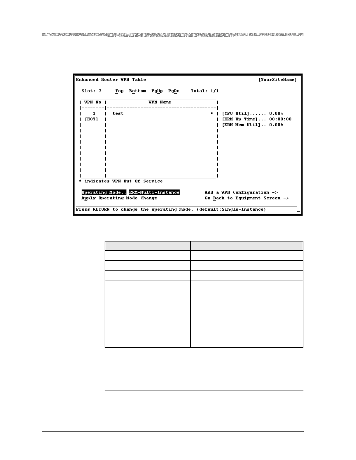
Chapter 3 Configuring VPNs Using the Console Interface
d
Configuring the Module
2 On the Equipment Configuration window, select an Enhanced Router
module.
The Enhanced Router VPN Table window is displayed (see Figure 3-4).
Figure 3-4. Enhanced Router VPN Table Window
The commands in this window have the following functions:
Command Function
Top Displays the first page of the table.
Bottom Displays the last page of the table.
PgUp Displays the previous page of the table.
PgDown Displays the next page of the table.
Apply Operating Mode
Change
Sets the operating mode of the module to
the value in the Operating Mode command field.
Add a VPN Configuration Displays the Enhanced Router VPN Con-
figuration window.
Go Back to Equipment
Screen
Redisplays the Equipment Configurat ion
window.
The fields on the VPN Table window are described in Table 3-1. If you want
to view the configuration for a module in a different slot, type the slot number where the module is inserted in the Slot field.
En
PacketStar® PSAX Enhanced Router Module User Guide, Issue 1 Release 9.1.0
3-4 255-700-614
Page 55

Chapter 3 Configuring VPNs Using the Console Interface
Table 3-1. ERM VPN Table Window Field Descriptions
Field Name Field Values Description
VPN No Default: N/A
Range: 1–8
Format: Numeric
VPN Name Default: N/A
Displays the VPN number on the Enhanced
Router module. [EOT] denotes the end of the
table.
Displays the optional user-defined name.
Range: 0–31
Format: ASCII char-
acter
Operating Mode Default: ERM-Sin-
gle-Instance
Range: N/A
Format: Predefin ed
Indicates the operating mode of the Enhanced
Router module.
Note: The Multi-Instance mode is not supported
on the Enhanced Router mod ule in Release 9.1 .0.
Do not perform configurations with the
Enhanced Router module in Multi-Instance
mode.
ERM-SingleInstance
ERM-Multi-
Indicates that only one VPN can be configured on
the module.
This field value is not currently supported.
Instance
Configuring VPNs
[CPU Util] Default: 0.00
Range: N/A
Format: Numeric
[ERM Up Time] Default: 00:00:00
Range: N/A
Format: hh:mm:ss
[ERM Mem Util] Default: 0.00
Range: 0–99
Format: Percent
Configuring VPNs
T o configure the Enhanc ed Route r module, p erform the following p rocedur e.
Begin
1 To configure the VPN, select the Add VPN command.
Displays the CPU's memory utilization as a per-
centage of total memory available per VPN.
Note: This field o nly updates when Operating
Mode is set to ERM-Single-Instance on the
Enhanced Router VPN Table window.
Displays the length of time that the module has
been active.
Note: This field o nly updates when Operating
Mode is set to ERM-Single-Instance.
Displays the module's memory utilization as a
percentage of total memory available per VPN.
Note: This field o nly updates when Operating
Mode is set to ERM-Single-Instance.
PacketStar® PSAX Enhanced Router Module User Guide, Issue1 Release9.1.0
255-700-614 3-5
Page 56
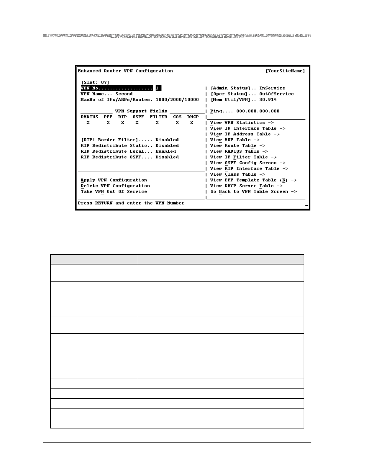
Chapter 3 Configuring VPNs Using the Console Interface
Configuring VPNs
The Enhanced Router VPN Configuration window is displayed (see
Figure 3-5).
Figure 3-5. Enhanced Router VPN Configuration Window
The value OutOfService is displayed in the [Oper Status] and [Admin
Status] fields.
The commands in this window have the following functions:
Command Function
Add VPN Configuration Crea tes a new VPN entry. After using this command, it
changes to the Apply Configuration command.
Delete VPN Configura ti on Deletes the current VPN entry that displays (if it was previ-
ously added).
Bring VPN Into Service Brings the out-of-service VPN to in-service status. The value
Inservice is displayed in the [Admin Status] field.
Take VPN Out of Service Brings the in-service VPN to out-of-service status. The value
OutOfService is displayed in the [Admin Status] field.
Ping Connectivity test to reac h a remot e IP de vice. After you have
completely configured a VPN, enter the IP address of the
node with which you want to connect.
View V PN Statistics Displays the Enhanced Router VPN ICMP Statistics window.
View IP Interfac e Table Displays the Enhanced Router IP I nterface Table window.
View IP Address Table Displays the Enhanced Router IP Address Table window.
View ARP Table Displays the Enhanced Router ARP Table window.
View Route Table Displays the Enhanced Router IP Route Table window.
View RADIUS Table Displays the Enhanced Router RADIUS Server Table window.
Note: This option is not currently supported.
PacketStar® PSAX Enhanced Router Module User Guide, Issue 1 Release 9.1.0
3-6 255-700-614
Page 57

Chapter 3 Configuring VPNs Using the Console Interface
Configuring VPNs
Command Function
View IP Filter Table Displays the Enhanced Router Filter Rule Table Table win-
dow.
Note: You cannot use this command until Enabled is
selected in the IP Filter Support field.
[View OSPF Config Screen] Displays the Enhanced Router OSPF General Configuration
window.
Note: You cannot use this command until Enabled is
selected in the OSPF Support field.
View RIP Interface Table Displays the Enhanced Router RIP2 Interface Table window.
Note: You cannot use this command until Enabled is
selected in the RIP Support field.
View Class Table Displays the Enhanced Router Class Table window.
View PPP Template Table Displays the Enhanced Router PPP Config Template Table
window.
Go Back to VPN Table
Screen
2 Select the values for the fields on this window from the values given in
3 To apply the values for the fields, select the Add VPN command.
4 To bring the VPN into service, select the Bring VPN Into Service com-
Note: You must complete step 4 above before you can configure and add
Redisplays the Enhanced Router VPN Table window.
Table 3-2.
mand.
an IP interface on the module.
PacketStar® PSAX Enhanced Router Module User Guide, Issue1 Release9.1.0
255-700-614 3-7
Page 58

Chapter 3 Configuring VPNs Using the Console Interface
Configuring VPNs
5 Repeat the steps in the “Accessing the VPN Configuration Table” proce-
dure to configure additional VPNs.
End
Table 3-2. Enhanced Router VPN Configuration Window Field Descriptions
Field Name Field Values Description
VPN No Default: 0
Displays the VPN identifier.
Range: 1–8
Format: Numeric
VPN Name Default: N/A
Displays an optional user-defined name, if any.
Range: 0–31
Format: ASCII char-
acter
Max No of Interfaces/ARPs/Routes
Default: 1024/2048/
10240
Range: 1–2048
(interfaces);
1–2048 (ARPs);
Displays the maximum number of entities to be
contained in this VPN for interfaces, ARPs, and
routes, respectively.
Note: You must enter 10240 for the number of
routes (the third value)
1–10,240 (routes)
Format: Numeric
VPN Support Fields Panel
RADIUS Default: (Blank)
This field is not currently supported.
Range: N/A
Format: Blank (unse-
lected) or X (s elected)
PPP Default: (Blank)
Range: N/A
Format: Blank (unse-
lected) or X (s elected)
Indicates whether the PPP protocol is supported
on this VPN. You cannot view or configure the
PPP configuration parameters unless this field is
set to the value Enabled.
Note: This field is only supported on VPN 1.
Disabled Indicates that PPP is not supported.
Enabled Indicates that PPP is supported.
RIP Default: (Blank)
Range: N/A
Format: Blank (unse-
lected) or X (s elected)
Indicates whether the RIP protocol is supported
on this VPN. You cannot view or configure the
RIP2 interface configuration parameters unless
this field is set to the value Enabled.
Disabled RIP support is disabled.
Enabled RIP support is enabled.
OSPF Default: (Blank)
This field is not currently supported.
Range: N/A
Format: Blank (unse-
lected) or X (s elected)
PacketStar® PSAX Enhanced Router Module User Guide, Issue 1 Release 9.1.0
3-8 255-700-614
Page 59

Chapter 3 Configuring VPNs Using the Console Interface
Table 3-2. Enhanced Router VPN Configuration Window Field Descriptions (Continued)
Field Name Field Values Description
FILTER Default: (Blank)
Range: N/A
Format: Blank (unse-
lected) or X (s elected)
Indicates whether IP fi ltering f eature is sup ported
on this VPN. Yo u canno t vie w or configur e t he IP
Filter Rule configuration parameters unless this
field is set to the value Enabled.
Disabled Indicates that IP filter is not supported on this
VPN.
Enabled Indicates that IP filter is supported on this VPN.
COS Default: (Blank)
Range: N/A
Format: Blank (unse-
lected) or X (s elected)
Indicates whether the class of service feature is
supported on this VPN.
Note: This field is display-only in Multi-Instance
mode.
Disabled Indicates that class of service is not supported on
this VPN.
Enabled Indicates that class of service is supported on this
VPN.
DHCP Default: (Blank)
Range: N/A
Format: Blank (unse-
Indicates whether DHCP Relay Agent support is
enabled on this VPN. This field is only supported
in Single-Instance mode.
lected) or X (s elected)
Disabled DHCP Relay Agent support is disabled.
Enabled DHCP Relay Agent support is enabled.
[RIP1 Border Filter] Default: Disabled
This field is not currently supported.
Range: N/A
Format: Predefin ed
RIP Redistribute
Static
Default: Disabled
Range: N/A
Format: Predefin ed
Indicates whether or not static routes on this
module will be redistributed during a RIP update
in the RIP advertisement on this VPN.
Note: This field is display-only when the RIP field
is unchecked.
Disabled Indicates that the static routes on this module
may be distributed through RIP advertisements.
Enabled Indicates that the static routes on this module
cannot be distributed through RIP advertise-
ments.
Configuring VPNs
PacketStar® PSAX Enhanced Router Module User Guide, Issue1 Release9.1.0
255-700-614 3-9
Page 60

Chapter 3 Configuring VPNs Using the Console Interface
Configuring VPNs
Table 3-2. Enhanced Router VPN Configuration Window Field Descriptions (Continued)
Field Name Field Values Description
RIP Redistribute
Local
Default: Enabled
Range: N/A
Format: Predefin ed
Indicates whether the local interface routes on
this module are to be distributed or not during a
RIP update in the RIP advertisement on this VPN.
Note: This field is display-only when the RIP field
is unchecked.
Enabled Indicates that the local interface routes on this
module may be distributed through RIP advertisements.
Disabled Indicates that the local interface routes on this
module cannot be distributed through RIP advertisements.
RIP Redistribute
OSPF
Default: Enabled
Range: N/A
This field is not currently supported.
Format: Predefin ed
Enabled Indicates that OSPF is used to redistribute RIP
routes on this VPN.
Disabled Indicates that OSPF is not used to redistribute RIP
routes on this VPN.
[Admin Status] Default: OutOfSer-
vice
Displays whether a user has requested that the
VPN be brought into service.
Range: N/A
Format: Predefin ed
Inservice Indicates that the no conditions are preventing
the VPN from being fully operational. A user has
requested that the VPN be brought into service.
OutOfService Indicates that some condition is preventing the
VPN from being configured. A use r has requeste d
that the VPN be taken out service.
PacketStar® PSAX Enhanced Router Module User Guide, Issue 1 Release 9.1.0
3-10 255-700-614
Page 61

Chapter 3 Configuring VPNs Using the Console Interface
Table 3-2. Enhanced Router VPN Configuration Window Field Descriptions (Continued)
Field Name Field Values Description
[Oper Status] Default: OutOfSer-
vice
Displays whether the VPN is fully operational or
not.
Range: N/A
Format: Predefin ed
Inservice Indicates that all IP interfaces and connections on
this VPN are operationa l.
OutOfService Indicates that a problem exists with an IP inter-
faces and connections on this VPN.
[Mem Util/VPN] Default: 0.00
Range: N/A
Format: Numeric
Displays the CPU’s memory utilization as a per-
centage of total memory available per VPN.
Note: This field o nly updates when Operating
Mode is set to ERM-Single-Instance on the
Enhanced Router VPN Table window.
Ping Default: 000.000.000.
000
Range: N/A
Indicates the IP address of the remote device to
reach. Enter the IP address of the node with
which you want to connect.
Format: Valid-dotted
quad
Configuring VPNs
Bringing VPNs Into and Out of Service
A VPN may be taken out of service or brought into service at any time by
using the commands on the Enhanced Router VPN Configuration window.
The VPN may not be brought into or out of service if the given VPN (or any
other VPN configured on a Enhanced Router module in the Multi-Instance
operating mode) is currently processing a user-initiated administrative command (the selection of a command on a configuration window). Under most
circumstances, this is not noticeable. However, when a VPN has several thousand configured interfaces, it may take several moments for the system software to issue the out-of-service command for each interface. During this
time, other administrative operations (possibly on other VPNs) cannot be
performed or processed.
The VPN must be administratively out-of-service prior to deletion. If only
operationally out of service, you must take the VPN administratively out-ofservice prior to deleting it.
Note: The Multi-Instance mode is not supported on the Enhanced Router
module in Release 9.1.0. Do not perform configurations with the
Enhanced Router module in Multi-Instance mode.
Deleting VPNs
Before deleting a VPN, it must first be taken out of service. The Delete command may be rejected if the preceeding out-of-service requests have not all
been issued.
PacketStar® PSAX Enhanced Router Module User Guide, Issue1 Release9.1.0
255-700-614 3-11
Page 62

Chapter 3 Configuring VPNs Using the Console Interface
Configuring VPNs
Deleting a VPN that is configured in Single-Instance mode will cause the
module to reboot.
Perform the following procedure to delete a VPN.
!
CAUTION:
Before you perform the following procedure, be awar e that if you delete
a VPN, all of the interfaces and connections created under the VPN are
also removed with the VPN.
Begin
1 On the Enhanced Router VPN Configuration window (see Figure 3-5),
select the Take VPN Out of Service command. A message appears at
the bottom of the window:
Are you sure you want to Take this VPN out of service? y/n
2 Type Y.
The VPN is taken out of service.
3 Select the Delete VPN command. A message appears at the bottom of
the window:
4 Type Y.
End
Viewing ICMP Statistics
To view ICMP statistics for this VPN, perform the following procedure.
Begin
1 Go to the Enhanced Router VPN Configuration window (see Figure3-5).
2 Select the View VPN Statistics command.
Are you sure you want to delete this VPN? y/n
The VPN is deleted. The Enhanced Router module will reboot.
PacketStar® PSAX Enhanced Router Module User Guide, Issue 1 Release 9.1.0
3-12 255-700-614
Page 63
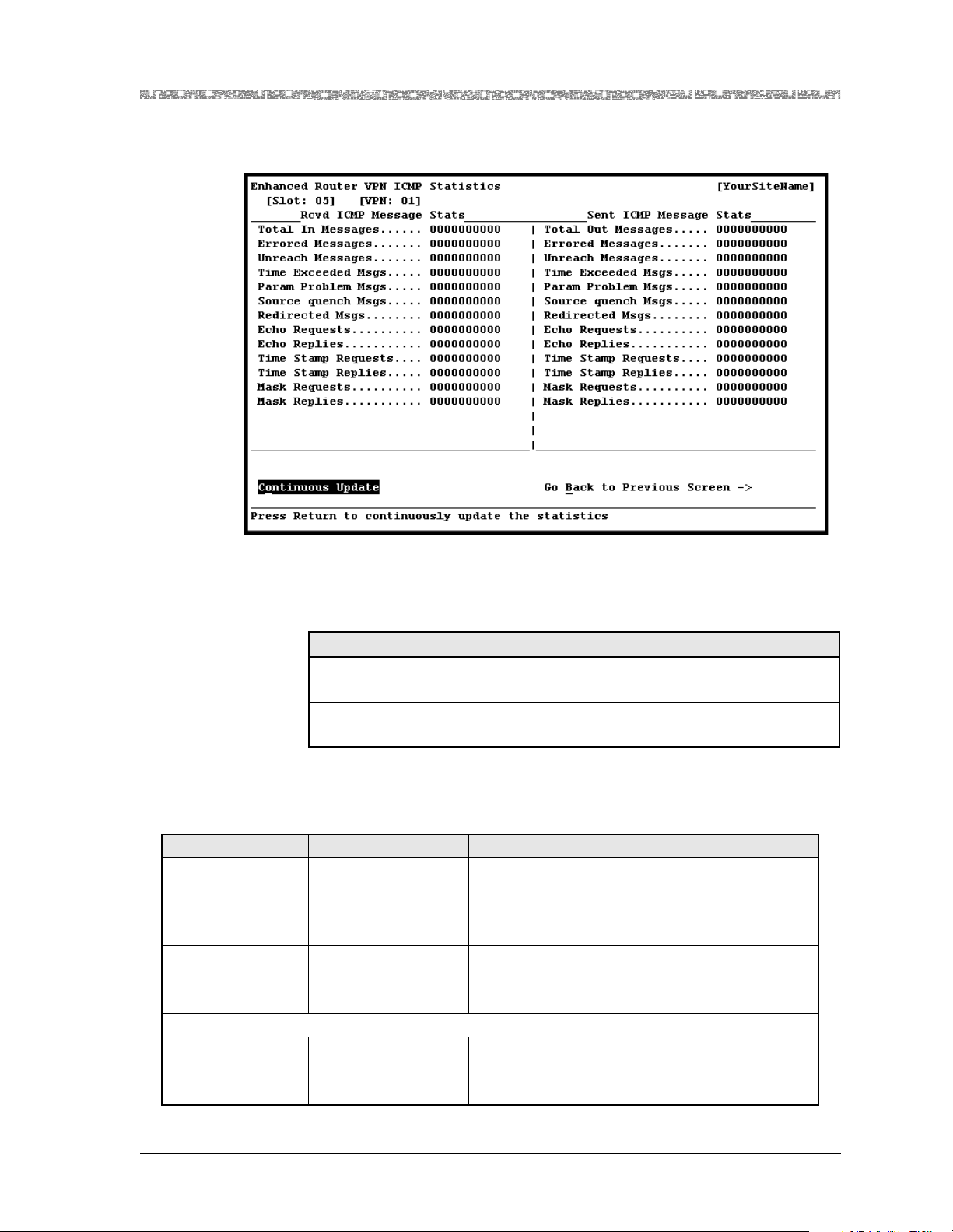
Chapter 3 Configuring VPNs Using the Console Interface
Configuring VPNs
The Enhanced Router VPN ICMP Statistics window is displayed (see
Figure 3-6).
Figure 3-6. Enhanced Router VPN ICMP Statistics Window
The commands in this window have the following functions:
Command Function
Continuous Update Updates the values constantly. Press any
key to stop the update.
Go Back to Previous Screen Redisplays the Enhanced Router VPN
Configuration window.
The display-only fields in this window are described in Table 3-3.
Table 3-3. Enhanced Router VPN ICMP Statistics Window Field Descriptions
Field Name Field Values Description
[Slot: ] Default: N/A
Range: Chassis
Displays the slot number where the Enhanced
Router module is installed in the PSAX chassis.
dependent
Format: Numeric
[VPN: ] Default: N/A
Range: 1–6
Identifies the VPN to which the ICMP statistics
refer.
Format: Numeric
Rcvd ICMP Message Stats (display only)
Total In Messages Default: 0
Range: N/A
Displays the total number of received ICMP mes-
sages on this VPN.
Format: Numeric
PacketStar® PSAX Enhanced Router Module User Guide, Issue1 Release9.1.0
255-700-614 3-13
Page 64

Chapter 3 Configuring VPNs Using the Console Interface
Configuring VPNs
Table 3-3. Enhanced Router VPN ICMP Statistics Window Field Descriptions (Continued)
Field Name Field Values Description
Errored Messages Default: 0
Range: N/A
Displays the number of errors in received ICMP
messages on this VPN.
Format: Numeric
Unreach Messages Default: 0
Range: N/A
Displays the number of received destination
unreachable messages on this VPN.
Format: Numeric
Time Exceeded
Msgs
Default: 0
Range: N/A
Displays the number of received time exceeded
messages on this VPN.
Format: Numeric
Param Problem
Msgs
Default: 0
Range: N/A
Displays the number of received parameter problem messages on this VPN.
Format: Numeric
Source quench
Msgs
Default: 0
Range: N/A
Displays the number of received source quenches
on this VPN.
Format: Numeric
Redirected Msgs Default: 0
Range: N/A
Displays the number of received redirected messages on this VPN.
Format: Numeric
Echo Requests Default: 0
Range: N/A
Displays the numbe r of receive d echo reques ts on
this VPN.
Format: Numeric
Echo Replies Default: 0
Range: N/A
Displays the number of received echo replies on
this VPN.
Format: Numeric
Time Stamp
Requests
Default: 0
Range: N/A
Displays the number of received time stamp
requests on this VPN.
Format: Numeric
Time Stamp Replies Default: 0
Range: N/A
Displays the number of received time stamp
replies on this VPN.
Format: Numeric
Mask Requests Default: 0
Range: N/A
Displays the number of received mask requests
on this VPN.
Format: Numeric
Mask Replies Default: 0
Range: N/A
Displays the number of received mask replies on
this VPN.
Format: Numeric
Sent ICMP Message Stats (display only)
Total Out Messages De fau lt: 0
Range: N/A
Displays the total num be r of s ent ICM P mess ag es
on this VPN.
Format: Numeric
PacketStar® PSAX Enhanced Router Module User Guide, Issue 1 Release 9.1.0
3-14 255-700-614
Page 65

Chapter 3 Configuring VPNs Using the Console Interface
Table 3-3. Enhanced Router VPN ICMP Statistics Window Field Descriptions (Continued)
Field Name Field Values Description
Errored Messages Default: 0
Range: N/A
Displays the number of errors in received ICMP
messages on this VPN.
Format: Numeric
Unreach Messages Default: 0
Range: N/A
Displays the number of transmitted destination
unreachable messages on this VPN.
Format: Numeric
Time Exceeded
Msgs
Default: 0
Range: N/A
Displays the number of transmitted time
exceeded messages on this VPN.
Format: Numeric
Param Problem
Msgs
Default: 0
Range: N/A
Displays the number of transmitted parameter
problem messages on this VPN.
Format: Numeric
Source quench
Msgs
Default: 0
Range: N/A
Displays the number of transmi tted source
quenches on this VPN.
Format: Numeric
Redirected Msgs Default: 0
Range: N/A
Displays the number of transmitted redirected
messages on this VPN.
Format: Numeric
Echo Requests Default: 0
Range: N/A
Displays the number o f transmitted echo requests
on this VPN.
Format: Numeric
Echo Replies Default: 0
Range: N/A
Displays the number of transmitted echo replies
on this VPN.
Format: Numeric
Time Stamp
Requests
Default: 0
Range: N/A
Displays the number of transmitted time stamp
replies on this VPN.
Format: Numeric
Time Stamp Replies Default: 0
Range: N/A
Displays the number of transmitted time stamp
requests on this VPN.
Format: Numeric
Mask Requests Default: 0
Range: N/A
Displays the number of transmitted mask
requests on this VPN.
Format: Numeric
Mask Replies Default: 0
Range: N/A
Displays the number of transmitted mask replies
on this VPN.
Format: Numeric
Configuring VPNs
Viewing IP Statistics
To view IP statistics for this VPN, go to the Enhanced Router VPN ICMP Statistics window and select the View IP Statistics Screen command.
PacketStar® PSAX Enhanced Router Module User Guide, Issue1 Release9.1.0
255-700-614 3-15
Page 66
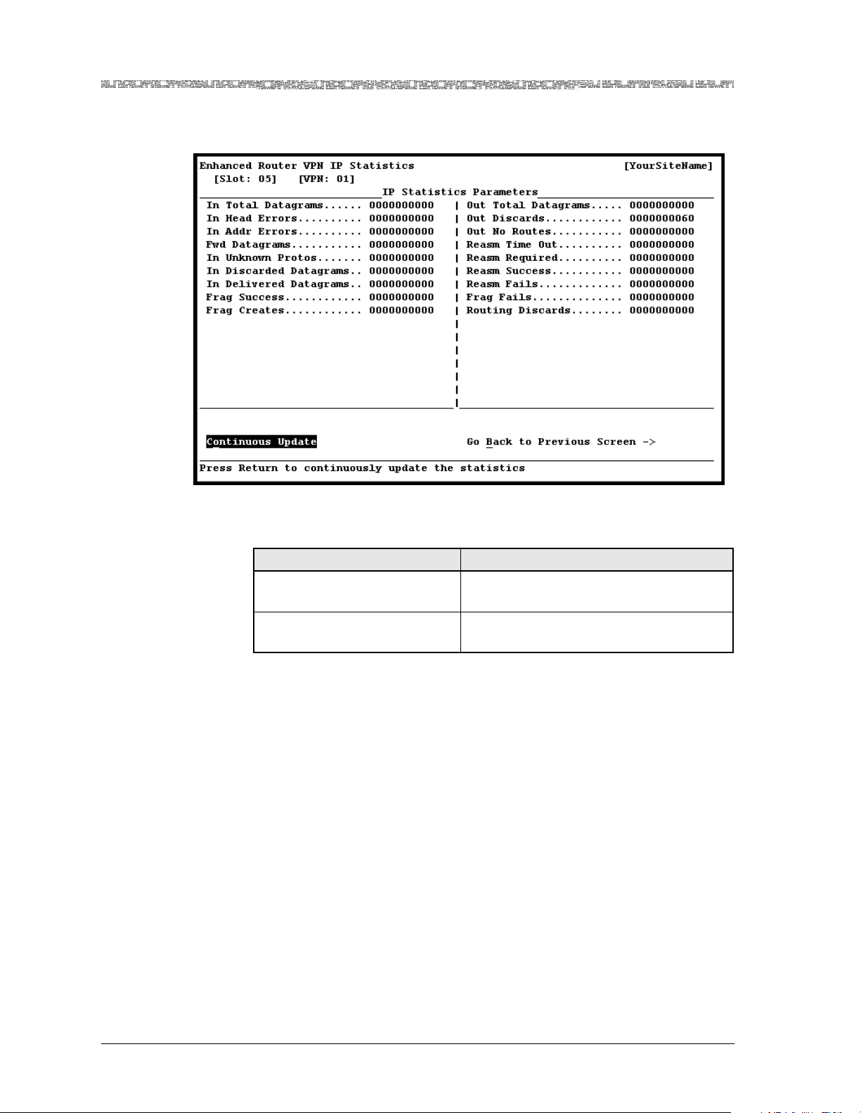
Chapter 3 Configuring VPNs Using the Console Interface
Configuring VPNs
The Enhanced Router VPN IP Statistics window is displayed (see
Figure 3-7).
Figure 3-7. Enhanced Router VPN IP Statistics Window
The commands in this window have the following functions:
Command Function
Continuous Update Updates the values constantly. Press any
key to stop the update.
Go Back to Previous Screen Redisplays the Enhanced Router VPN
ICMP Statistics window.
The display-only fields in the VPN Statistics window are described in
Table 3-4.
PacketStar® PSAX Enhanced Router Module User Guide, Issue 1 Release 9.1.0
3-16 255-700-614
Page 67

Chapter 3 Configuring VPNs Using the Console Interface
Table 3-4. ERM VPN IP Statistics Window Field Descriptions
Field Name Field Values Description
In Total Datagrams Default: 0
Range: N/A
Format: Numeric
In Head Errors Default: 0
Range: N/A
Format: Numeric
Displays the total number of input datagrams
received from interfaces on this VPN, including
those received in error.
Displays the number of input datagrams dis-
carded due to errors in their IP headers, including
bad checksums, version number mismatch, other
format errors, time-to-live exceeded, errors dis-
covered in processing their IP options.
In Addr Errors Default: 0
Range: N/A
Format: Numeric
Displays the number of input datagrams dis-
carded because the IP address in their IP header’s
destination field was not a valid address to be
received at this entity. This count includes invalid
addresses and addresses of unsupported classes.
For entities which are not IP routers and there-
fore do not forward datagrams, this counter
includes datagrams discarded because t he desti-
nation address was not a local address.
Fwd Datagrams Default: 0
Range: N/A
Format: Numeric
Displays the number of input datagrams for
which this entity was not their final IP destina-
tion, as a result of wh ich an at tempt was ma de to
find a route to forward them to that final destina-
tion. In entities which do not act as IP routers,
this counter will include only those packets
which were Source-Routed via this entity, and
the Source-Route option processing was success-
ful.
In Unknown Protos Default: 0
Range: N/A
Format: Numeric
In Discarded Datagrams
Default: 0
Range: N/A
Format: Numeric
Displays the number of locally-addressed data-
grams received successfully but discarded because
of an unknown or unsupported protocol.
Displays the number of input IP datagrams for
which no problems were encountered to prevent
their continued processing, but which were dis-
carded (for example, for lack of buffer space).
This field does not include any datagrams dis-
carded while awa i ti ng rea s se m bly.
In Delivered Datagrams
Frag Success Default: 0
Default: 0
Range: N/A
Format: Numeric
Range: N/A
Displays the total number of input datagrams
successfully delivered to IP user-protocols
(including ICMP).
Displays the number of IP datagrams that have
been successfully fragmented at this VPN.
Format: Numeric
Frag Creates Default: 0
Range: N/A
Format: Numeric
Displays the number of IP datagram fragments
that have been generated as a result of fragmen-
tation at this VPN.
Configuring VPNs
PacketStar® PSAX Enhanced Router Module User Guide, Issue1 Release9.1.0
255-700-614 3-17
Page 68

Chapter 3 Configuring VPNs Using the Console Interface
Configuring VPNs
Table 3-4. ERM VPN IP Statistics Window Field Descriptions (Continued)
Field Name Field Values Description
Out Total Datagrams
Default: 0
Range: N/A
Format: Numeric
Displays the total number of IP datagrams which
local IP user-protocols (including ICMP) supplied
to IP in requests for transmission. This field does
not include any datagrams counted in the Fwd
Datagrams field.
Out Discards Default: 0
Range: N/A
Format: Numeric
Displays the number of output IP datagrams for
which no problem was encountered to prevent
their transmission to their destination, but which
were discarded (for example, for lack of buffer
space). This field includes datagrams counted in
the Fwd Datagrams field when packets meet this
discard criterion.
Out No Routes Default: 0
Range: N/A
Format: Numeric
Displays the number of IP datagrams discarded
because no route could be found to transmit
them to their destination. This field includes any
packets counted in the Fwd Datagrams field that
meet this “no-route” criterion. This field includes
any datagrams which a host cannot route
because all of its default routers are down.
Reasm Time Out Default: 0
Range: N/A
Format: Numeric
Reasm Required Default: 0
Range: N/A
Displays the maximum number of seconds which
received fragments are hel d wh ile they ar e awa iting reassembly at this VPN.
Displays the number of IP fragments received
which needed to be reassembled at this VPN.
Format: Numeric
Reasm Success Default: 0
Range: N/A
Displays the numbe r o f IP da tag ram s su ccessfully
reassembled on this VPN.
Format: Numeric
Reasm Fails Default: 0
Range: N/A
Format: Numeric
Displays the nu mber of f ailures detected by the IP
reassembly algori thm ( for whate ver re as on : t ime outs, errors, and so on). This field does not necessarily record the number of discarded IP fragments, since some algorithms (notably the
algorithm in RFC 815) can lose track of the number of fragments by combining them as they are
received.
Frag Fails Default: 0
Range: N/A
Format: Numeric
Displays the number of IP datagrams that have
been discarded because they needed to be fragmented at this VPN but could not be fragmented,
due to some error.
Routing Discards Default: 0
Range: N/A
Format: Numeric
Displays the number of routing entries which
were chosen to be discarded even though they
are valid. One possible reason for discarding such
an entry could be to free-up buffer space for
other routing entries.
PacketStar® PSAX Enhanced Router Module User Guide, Issue 1 Release 9.1.0
3-18 255-700-614
Page 69
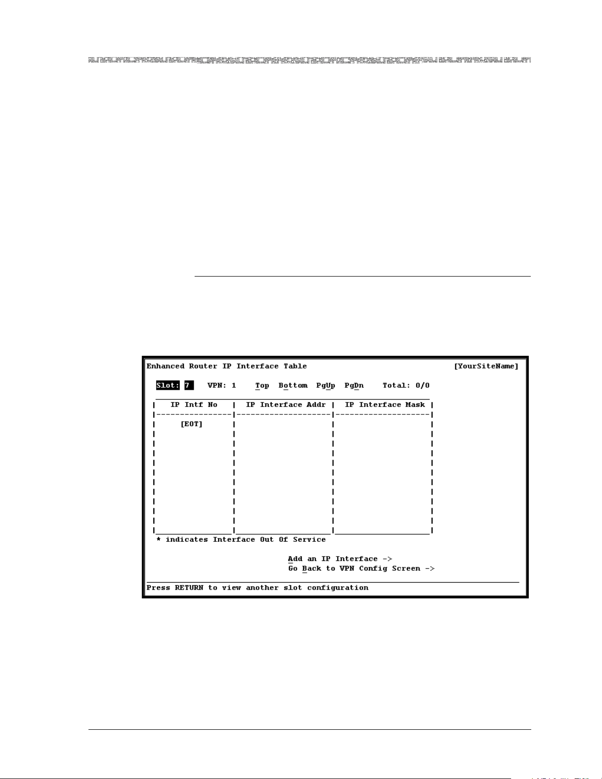
Chapter 3 Configuring VPNs Using the Console Interface
Configuring IP Interfaces
An IP interface identifies one of the VPN’s locally attached networks, and
associates an IP interface address with the network. By creating an IP interface, a route is automatically created in the IP route table of the VPN. When
configuring an IP interface, it is possible to assign connections corresponding
to a specific traffic treatment.
Note: You must bring the parent VPN into service before you can add an
IP interface.
Setting the Values for IP Interfaces
To view the Enhanced Router Interface Table, perform the following procedure.
Begin
1 On the Enhanced Router VPN Configuration window, select the View IP
Interface Table command.
Configuring IP Interfaces
The Enhanced Router Interface Table window is displayed (see
Figure 3-8).
Figure 3-8. Enhanced Router Interface Table Window (Before Configuration)
The Enhanced Router Interface Table window allows you to view all interface numbers, interface addresses and interface masks of your configuration.
The commands in this window have the following functions:
PacketStar® PSAX Enhanced Router Module User Guide, Issue1 Release9.1.0
255-700-614 3-19
Page 70
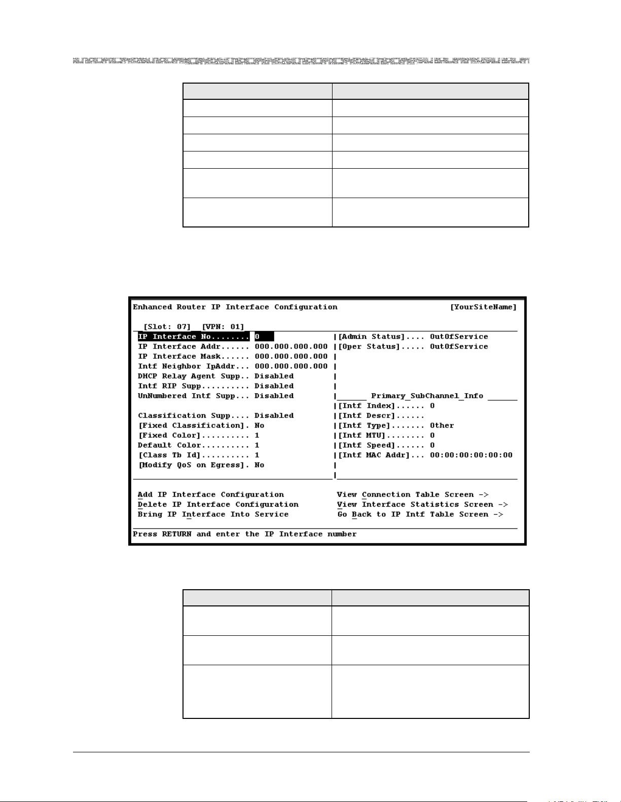
Chapter 3 Configuring VPNs Using the Console Interface
Configuring IP Interfaces
Command Function
Top Displays the first page of the table.
Bottom Displays the last page of the table.
PgUp Displays the previous page of the table.
PgDown Displays the next page of the table.
Add an IP Interface Displays the Enhanced Router IP Interface
Configuration window.
Go Back to VPN Config
Screen
Displays the Enhanced Router VPN Configuration window.
2 Select the Add an IP Interface command.
The Enhanced Router IP Interface Configuration window is displayed
(see Figure 3-9).
Figure 3-9. Enhanced Router IP Interface Configuration Window
The commands in this window have the following functions:
Command Function
Add IP Interface Configura-
Creates a new interface.
tion
Delete IP Interface Configu-
ration
Bring IP Interface Into Ser-
vice
Deletes the current IP network interface
that is displayed (if it previously existed).
Brings the out-of-service IP network
interface to in-service status. The value
Inservice is displayed in the [Admin Status] field.
PacketStar® PSAX Enhanced Router Module User Guide, Issue 1 Release 9.1.0
3-20 255-700-614
Page 71

Chapter 3 Configuring VPNs Using the Console Interface
d
Command Function
T ake IP Inte rf ace Out of Service
View Connection Table
Screen
Configuring IP Interfaces
Takes the in-service IP network interface
to out-of-service stat us. Th e valu e OutOf-
Service is displayed in the [Admin Status]
field.
Displays the Enhanced Router Conne ction
Table window.
View Interface Statistics
Screen
Go Back to IP Intf Table
Screen
Displays the Enhanced Router VPN IP Statistics window.
Redisplays the Enhanced Ro uter IP Interface Table window.
3 Enter the values for the fields on this window according to the informa-
tion provided in Table 3-5.
4 To apply the values for the fields, select the Add Interface Configura-
tion command.
The interface is displayed in the Enhanced Router Interface Table window.
Note: If the class of service feature is enabled (using the Classification
Supp field) on the IP interface you configured, y ou must set up the
desired conne ctions f or this IP interf ace befo re you can bring t he IP
interface into service.
5 To bring the IP interface into service, select the Bring Interface Into
Service command.
The value InService is displayed in the [Admin Status] field.
Note: The parent VPN must be in service before you can bring any of its
subordinate IP interfaces into service.
En
Table 3-5. Enhanced Router IP Interface Configuration Window Field Descriptions
Field Name Field Values Description
[Slot: ] Default: N/A
Range: N/A
Displays the slot containing the Enhanced Router
module.
Format: Numeric
[VPN: ] Default: N/A
Range: N/A
Displays the VPN identifier within which this IP
interface is contained.
Format: Numeric
IP Interface No Default: 0
Range: 1–2048
Indicates the unique IP interface number within
this VPN.
Format: Numeric
PacketStar® PSAX Enhanced Router Module User Guide, Issue1 Release9.1.0
255-700-614 3-21
Page 72

Chapter 3 Configuring VPNs Using the Console Interface
Configuring IP Interfaces
Table 3-5. Enhanced Router IP Interface Configuration Window Field Descriptions (Continued)
Field Name Field Values Description
IP Interface Addr Default: 000.000.000.
000
Range: N/A
Format: IP Address
Indicates the IP address of the enterp rise network
to which this IP interface is attached. This value is
strictly checked for network consistency with
other IP interfaces defined on the given VPN.
Note: This field must be specified if you are configuring this IP interface as an unnumb ered in terface.
IP Interface Mask Default: 000.000.000.
000
Range: N/A
Format: IP Address
Indicates the IP subnet mask of the ente rprise
network to which this IP interface is attached.
This value is strictly checked for network consistency with other IP interfaces defined on the
given VPN. Variable subnetting is allowed provided the netmask has at least 2 host bits.
Intf Neighbor
IpAddr
Default: 000.000.000.
000
Range: N/A
Format: IP Address
Indicates the IP address of the next hop IP address
for point-to-point connections.
Note: If you plan to configure a bridge, PPP, or
PPP over HDLC connection, or set up a 1xEVDO
application (which involves an HDLC connection), leave this field blank. This field must be
specified for ATM and frame relay connections,
and if you are configuring this IP interface as an
unnumbered interface.
DHCP Relay Agent
Supp
Default: Disabled
Range: N/A
Format: Predefin ed
Indicates whether DHCP Relay Agent support is
enabled.
Note: This field is only supported in SingleInstance mode.
Note: This field is display-only when the
UnNumbered Intf Supp field is set to Enabled.
Disabled Indicates that DHCP Relay Agent support is dis-
abled.
Enabled Indicates that DHCP Relay Agent support is
enabled.
Intf RIP Supp Default: Disabled
Range: N/A
Indicates whether RIP is supported on this IP
interface.
Format: Predefin ed
Disabled Indicates that RIP is not supported on this IP
interface. You will not be able to access the RIP
Interface Table or RIP Interface Configuration
windows.
Note: Y ou must select this value if you plan to set
up a 1xEVDO application.
Enabled Indicates that RIP is supported on this IP inter-
face. You will have access to the RIP Interface
Table and RIP Interface Configuration windows
to set additional values as desired.
PacketStar® PSAX Enhanced Router Module User Guide, Issue 1 Release 9.1.0
3-22 255-700-614
Page 73

Chapter 3 Configuring VPNs Using the Console Interface
Configuring IP Interfaces
Table 3-5. Enhanced Router IP Interface Configuration Window Field Descriptions (Continued)
Field Name Field Values Description
UnNumbe red Intf
Supp
Default: Disabled
Range: N/A
Indicates whether the unnumbered IP interface
type is supported on this IP interface.
Format: Predefin ed
Disabled Indicates that this IP interface is not an unnum-
bered interface.
Note: Selecting this value will make the first
three fields on this window become display-only
fields.
Note: Y ou must select this value if you plan to set
up a 1xEVDO application.
Enabled Indicates that this IP interface is an unnumbered
interface.
Classification Supp Default: Disabled
Range: N/A
Format: Predefin ed
Indicates whether the user wants classification to
be supported on this IP interface.
Note: This field is display-only when the
UnNumbered Intf Supp field is set to Enabled.
Disabled Indicates that classificatio n is not configured to be
supported on this IP interface.
Note: Y ou must select this value if you plan to set
up a 1xEVDO application.
Enabled Indicates that classification is configured to be
supported on this IP interface.
[Fixed Classification]
Default: No
Range: N/A
Specifies whether fixed classification is supported
on this IP interface.
Format: Predefin ed
No Specifies that, on this IP interface, fixed classifica-
tion is not supported, and a table-based classifica-
tion scheme (DSCP, subchannel) is supported.
Yes Specifies that, on this IP interface, fixed classifica-
tion is supported, and a table-based classification
scheme (DSCP, subchannel) is not supported.
[Fixed Color] Default: 0
Range: 1–6
Displays the fixed classification color when the
[Fixed Classification] field is set to Yes.
Format: Numeric
Default Color Default: 0
Range: 1–6
Format: Numeric
Indicates the default color on this IP interface
when the [Fixed Classification] field is set to No.
Unused values in the Enhanced Router Class
Rule Table are assigned the user-defined number
selected for this field.
Note: This field is only applicable to the DSCP
classification scheme.
Note: This field is display-only when the
UnNumbered Intf Supp field is set to Enabled.
PacketStar® PSAX Enhanced Router Module User Guide, Issue1 Release9.1.0
255-700-614 3-23
Page 74

Chapter 3 Configuring VPNs Using the Console Interface
Configuring IP Interfaces
Table 3-5. Enhanced Router IP Interface Configuration Window Field Descriptions (Continued)
Field Name Field Values Description
[Class Tb Id] Default: 0
Range: 1–6
Format: Numeric
[Modify QoS on
Egress]
Default: No
Range: N/A
Displays the applied class of service table index
number when the [Fixed Classification] field is
set to No.
This field is not currently supported.
Format: Predefin ed
[Admin Status] Default: OutOfSer-
vice
Indicates the user-requested state of the IP inter-
face.
Range: N/A
Format: Predefin ed
OutOfService Indicates that the IP interface has not been con-
figured, or that the user has requested to take an
IP interface out of service.
InService Indicates that the user has requested to put an IP
interface in service.
[Oper Status] Default: OutOfSer-
vice
Indicates the current operational state of th e IP
interface.
Range: N/A
Format: Predefin ed
OutOfService Indicates that the IP interface has not been con-
figured.
InService Indicates that the IP interface has been config-
ured and brought into service .
Unlocked-Init Indicates that the IP interface has been config-
ured and is initializing.
Unlocked-Disable Indicates that the IP interface has been config-
ured and is disabled .
Locked-Shutting Indicates that the IP interface has not been con-
figured and is shutting down.
Primary SubChannel Info Panel
[Intf Index] Default: 0
Range: See description
Format: Numeric
Displays a unique value for each IP interface. This
value ranges between 1 and the value of the IP
Intf No field. The value fo r each IP inte rfac e must
remain constant at least from one reinitialization
of the IP interface's net work management sy stem
to the next reinitialization.
[Intf Descr] Default: 0
Range: N/A
Format: Alphanu-
meric
Displays a text string containing information
about the IP interface. This string should include
the name of the manufacturer , the product name
and the version of the hardware interface.
PacketStar® PSAX Enhanced Router Module User Guide, Issue 1 Release 9.1.0
3-24 255-700-614
Page 75

Chapter 3 Configuring VPNs Using the Console Interface
Configuring IP Interfaces
Table 3-5. Enhanced Router IP Interface Configuration Window Field Descriptions (Continued)
Field Name Field Values Description
[Intf Type] Default: Other
Range: N/A
Format: Predefin ed
Displays the type of IP interface on this VPN, distinguished according to the physical/link protocol(s) immediately below the network layer in
the protocol stack.
Other Indicates that the type of IP interface on this VPN
cannot be determined. This could mean an error
or it could mean that the IP interf ace type has not
been defined.
Ethernet Indicates that the type of IP interface on this VPN
is Ethernet.
PPP Indicates that the type of IP interf ace on this VPN
is PPP.
Frame-Relay Indi cates that the typ e of IP inter face on thi s VPN
is Frame Relay.
ATM Indicates that the type of IP interf ace on this VPN
is ATM.
HdlcPassThrough Indicates that the type of IP interface on this VPN
is HDLC Passthrough.
[Intf MTU] Default: 0
Range: N/A
Format: Octets
Displays the size of the largest datagram which
can be sent/received on the IP interface. For IP
interfaces that are used for transmitting network
datagrams, this is the size of the largest network
datagram that can be sent on the IP interface.
[Intf Speed] Default: 0
Range: N/A
Displays an estimate of the IP interface's current
bandwidth.
Format: Bits per second
[Intf MAC Addr] Default: 0
Range: N/A
Format: Hexadecimal
Displays the IP interface address at the protocol
layer immediately below the network layer in the
protocol stack.
Class of Service Configuration Examples
Three different examples are illustrated below for interface creation with
regard to class of service.
Example 1. if Classification Sup p—Disabled
[Fixed Classification]—No
[Fixed Color]—1
[Default Color]—1
[Classification Tb Id]—0
[Modify QoS on Egress]—No
Example 2. if Classification Sup p—Enabled
PacketStar® PSAX Enhanced Router Module User Guide, Issue1 Release9.1.0
255-700-614 3-25
Page 76

Chapter 3 Configuring VPNs Using the Console Interface
Configuring IP Interfaces
Fixed Classification—Yes
Fixed Color—3
[Default Color]—1
[Classification Tb Id]—01
[Modify QoS on Egress]—No
Example 3. if
1
Classification Supp...... Enabled
Fixed Classification—No
[Fixed Color]—1
Default Color—1
Classification Tb Id—05
[Modify QoS on Egress]—No
Configuring Unnumbered Interfaces
T o configure a n IP interface as an unn umbered interface, p erform the st eps in
the section, “Setting the Values for IP Interfaces,” with special attention to
the following fi eld va lues o n the Enh anced Ro uter I P Inter face Co nfigura tion
window:
• Specify a value in the IP Interface Addr and Intf Neighbor IpAddr fields.
• Select Enabled in the UnNumbered Intf Supp field.
Viewing Interface Statistics
To view the statistics for this IP interface, perform the following procedure.
Begin
1 Go to the Enhanced Router IP Interface Configuration window.
2 Select the View Interface Statistics Screen command.
1
If using the method shown in Example 3, the classification Table 5 must be previously created in a different step. For more information, see the section, “Configur-
ing Class of Service Parameters.”
PacketStar® PSAX Enhanced Router Module User Guide, Issue 1 Release 9.1.0
3-26 255-700-614
Page 77
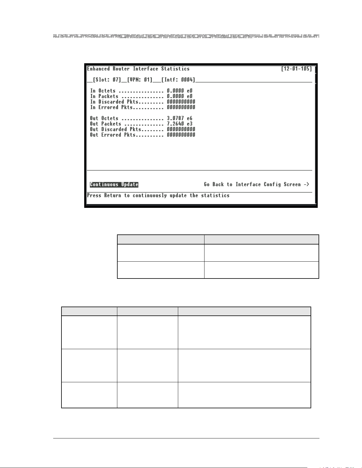
Chapter 3 Configuring VPNs Using the Console Interface
Configuring IP Interfaces
The Enhanced Router Interface Statistics window is displayed (see
Figure 3-10).
Figure 3-10. Enhanced Router Interface Statistics Window
The commands in this window have the following functions:
Command Function
Continuous Update Updates the values constantly. Press any
key to stop the update.
Go Back to Interface Config
Screen
Redisplays the En hanced Ro uter Inte rface
Configuration window.
The display-only fields in this window are described in Table 3-6.
Table 3-6. Enhanced Router Interface Statistics Window Field Descriptions
Field Name Field Value Description
In Octets Default: 0
Range: N/A
Format: Scientific
Indicates the total number of input datagrams
(octets) received on this IP interface, including
those received in error.
notation
In Packets Default: 0
Range: N/A
Indicates the total number of packets rece ived on
this IP interface, including those received in error.
Format: Scientific
notation
Discarded Inbound
Pkts
Default: 0
Range: N/A
Format: Numeric
Indicates the total number of datagrams that
should be sent to this IP interface, but which
were discarded due to the IP throttling feature.
PacketStar® PSAX Enhanced Router Module User Guide, Issue1 Release9.1.0
255-700-614 3-27
Page 78

Chapter 3 Configuring VPNs Using the Console Interface
d
Configuring IP Interfaces
Table 3-6. Enhanced Router Interface Statistics Window Field Descriptions (Continued)
Field Name Field Value Description
In Errored Pkts Default: 0
Range: N/A
Format: Numeric
Out Octets Default: 0
Range: N/A
Indicates the number of inbound packets that
contained errors preve nting them from being
deliverable to a higher-layer protocol.
Indicates the total number of output datagrams
(octets) sent from this IP interface.
Format: Scientific
notation
Out Packets Default: 0
Range: N/A
Indicates the total number of packets sent from
this IP interface.
Format: Scientific
notation
Out Discarded
Packets
Default: 0
Range: N/A
Format: Numeric
Indicates the number of outbound packets which
were chosen to be discarded by IP throttling feature even though no errors had been detected to
prevent their being deliverable to a higher-layer
protocol. One possible reason for discarding such
a packet could be to free up buffer space.
Out Errored Pkts Default: 0
Range: N/A
Indicates the number of outbound packets that
could not be transmitted because of errors.
Format: Numeric
Deleting an IP Interface
If you want to delete an IP interface, you must first take the IP interface to
out-of-service status. Perform the following procedure to delete a IP interface.
Deleting an Interface
Begin
1 On the Enhanced Router Interface Configuration window (see
2 Type Y.
3 Select the Delete Interface Configuration command.
4 Type Y.
En
Figure 3-9), select the Take Interface Out of Service command.
The following message appears at the bottom of the window:
Are you sure you want to take this interface out of service?
y/n
The interface is taken out of service.
The following message appears at the bottom of the window:
Are you sure you want to delete this interface? y/n
The IP interface is deleted.
PacketStar® PSAX Enhanced Router Module User Guide, Issue 1 Release 9.1.0
3-28 255-700-614
Page 79
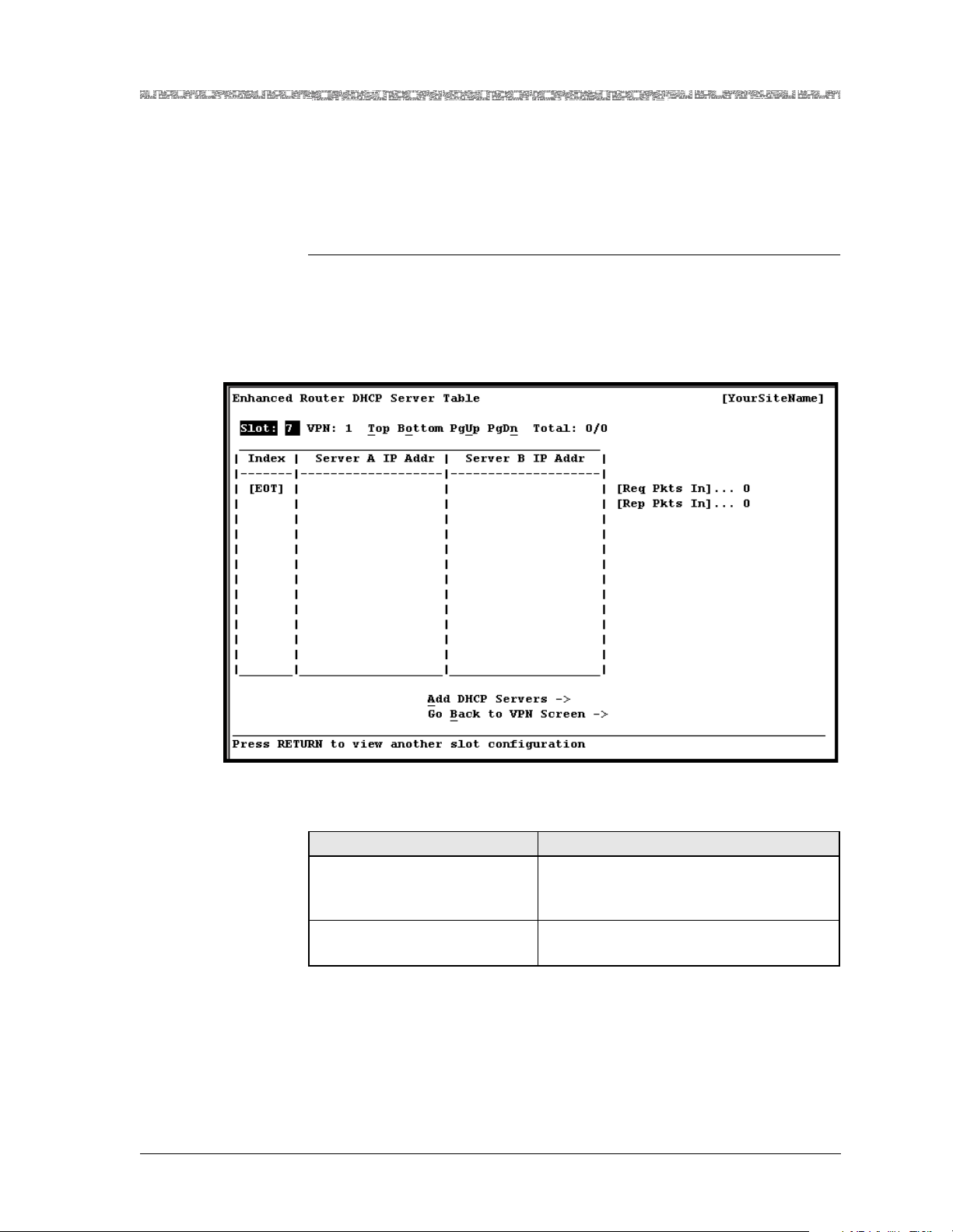
Chapter 3 Configuring VPNs Using the Console Interface
Viewing and Configuring DHCP Servers
To configure and/or view a DHCP server, perform the following procedure.
Note: You must enable DHCP on the Enhanced Router VPN Configura-
tion window before you can proceed.
Begin
1 On the Enhanced Router VPN Configuration window, select the View
DHCP Server Table command.
The Enhanced Router DHCP Server Table window is displayed (see
Figure 3-11).
Viewing and Configuring DHCP Servers
Figure 3-11. Enhanced Router DHCP Server Table Window
The commands in this window have the following functions:
Command Function
Add DHCP Servers Saves the DHCP Server entry to the
Enhanced Router DHCP Server Configuration window.
Go Back to VPN Screen Redisplays the Enhanced Router VPN
Configuration window.
The fields on this window are described in Table 3-7.
PacketStar® PSAX Enhanced Router Module User Guide, Issue1 Release9.1.0
255-700-614 3-29
Page 80
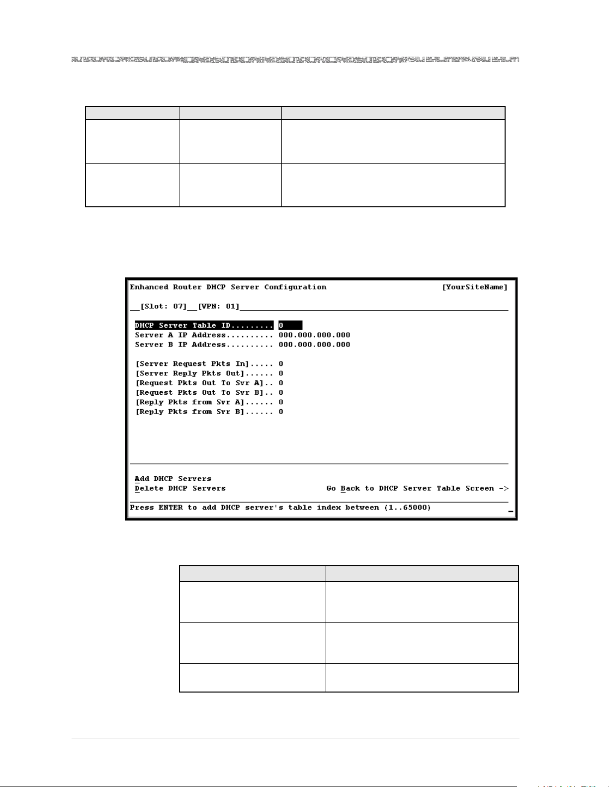
Chapter 3 Configuring VPNs Using the Console Interface
Viewing and Configuring DHCP Servers
Table 3-7. Enhanced Router DHCP Server Table Window Field Descriptions
Field Name Field Values Description
[Req Pkts In] Default: 0
Range: N/A
Format: Numeric
[Rep Pkts In] Default: 0
Range: N/A
Displays the total number of request packets
received by the primary and backup DHCP servers.
Displays the total number of reply packets transmitted by the primary and backup DHCP servers.
Format: Numeric
2 Select the Add DHCP Servers command.
The Enhanced Router DHCP Server Configuration window is displayed
(see Figure 3-12).
Figure 3-12. Enhanced Router DHCP Server Configuration Window
The commands in this window have the following functions:
Command Function
Add DHCP Servers Saves the DHCP Server entry to the
Enhanced Router DHCP Server Table window.
Delete DHCP Servers Removes the DHCP Server entry from the
Enhanced Router DHCP Server Table window.
Go Back to DHCP Server
Table Screen
PacketStar® PSAX Enhanced Router Module User Guide, Issue 1 Release 9.1.0
3-30 255-700-614
Redisplays the Enhanced Router DHCP
Server Table window.
Page 81

Chapter 3 Configuring VPNs Using the Console Interface
Viewing and Configuring DHCP Servers
3 Select the values for the fields on this window from the values given in
Table 3-8.
4 To apply the values for the fields, select the Add DHCP Servers com-
mand.
5 Once the DHCP server configuration is added or deleted, you can view
the updated Enhanced Router DHCP Server Table window by selecting
the Go Back to DHCP Server Table Screen command.
End
Table 3-8. Enhanced Router DHCP Server Configuration Window Field Descriptions
Field Name Field Values Description
[Slot: ] Default: N/A
Range: Varies
Displays the slot number where the Enhanced
Router module is installed in the PSAX chassis.
depending on chassis
type
Format: Numeric
[VPN: ] Default: N/A
Range: 1–6
Format: Numeric
DHCP Server Table IDDefault: 1
Range: 1–65000
Format: Numeric
Identifies the VPN where this DHCP server configuration resides. DHCP relay support is supported in Single-Instance mode only (VPN 1).
Specifies the unique identifier for this DHCP
server configuration.
Note: You must also specify this value in the
DHCP Server Tbl Id field when setting up a connection.
Server A IP Address Default: 000.000.000.
000
Range: N/A
Specifies the IP address of the primary DHCP
server through which DHCP packets are transmitted.
Format: IP address
Server B IP Address Default: 000.000.000.
000
Range: N/A
Format: IP address
Specifies the IP address of the backup DHCP
server through which DHCP packets are transmitted. This server will be used if the primary
DHCP server is down.
Note: This field is optional; you may leave the
default value as is if you do not want to specify a
backup DHCP server.
[Server Request
Pkts In]
[Server Reply Pkts
Out]
Default: 0
Range: N/A
Format: Numeric
Default: 0
Range: N/A
Displays the total number of request packets
received by the primary and backup DHCP servers.
Displays the total number of reply packets transmitted by the primary and backup DHCP servers.
Format: Numeric
[Request Pkts Out
to Svr A]
Default: 0
Range: N/A
Displays the total number of request packets
received by the primary DHCP server.
Format: Numeric
PacketStar® PSAX Enhanced Router Module User Guide, Issue1 Release9.1.0
255-700-614 3-31
Page 82
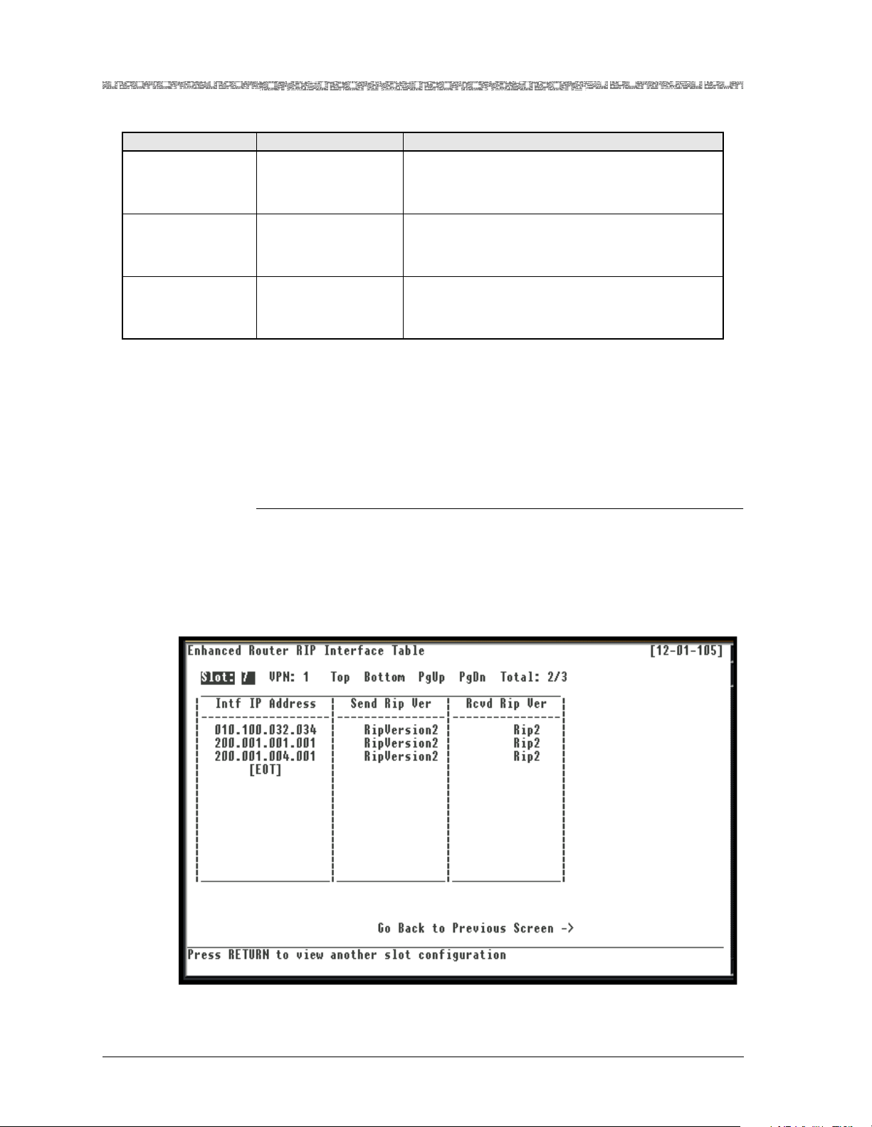
Chapter 3 Configuring VPNs Using the Console Interface
Viewing and Updating RIP Interfaces
Table 3-8. Enhanced Router DHCP Server Configuration Window Field Descriptions
Field Name Field Values Description
[Request Pkts Out
to Svr B]
[Reply Pkts from
Svr A]
[Reply Pkts from
Svr B]
Default: 0
Range: N/A
Format: Numeric
Default: 0
Range: N/A
Format: Numeric
Default: 0
Range: N/A
Format: Numeric
Displays the total number of request packets
received by the backup DHCP server.
Displays the total number of reply packets transmitted by the primary DHCP server.
Displays the total number of reply packets transmitted by the backup DHCP serv er.
Viewing and Updating RIP Interfaces
Viewing the RIP Interface Table
To view the RIP interface table, perform the following procedure.
Begin
1 Go to the Enhanced Router VPN Configuration window.
2 Select the View RIP Interface Table command.
The Enhanced Router RIP Interface Table window is displayed (see
Figure 3-13).
Figure 3-13. Enhanced Router RIP Interface Table Window
PacketStar® PSAX Enhanced Router Module User Guide, Issue 1 Release 9.1.0
3-32 255-700-614
Page 83

Chapter 3 Configuring VPNs Using the Console Interface
You cannot add RIP interfaces. The RIP interfaces displayed in the Enhanced
Router RIP Interface Table window are automatically populated after the IP
interface is created, if RIP is enabled on the VPN.
The command in this window has the following function:
Command Function
Top Displays the first page of the table.
Bottom Displays the last page of the table.
PgUp Displays the previous page of the table.
PgDown Displays the next page of the table.
Go Back to Previous Screen Redisplays the Enhanced Router VPN
Configuration window.
The values for the fields on this window are provided in Table 3-9.
Table 3-9. Enhanced Router RIP Interface Table Window Field Descriptions
Field Name Field Values Description
Slot: Default: N/A
Range: Chassis depen-
Displays the slot number where the Enhanced
Router module is installed in the PSAX chassis.
dent
Format: Numeric
VPN: Default: N/A
Identifies the VP N where this IP route resides.
Range: 1–6
Format: Numeric
Intf IP Address Default: N/A
Range:
Format:
Indicates the IP address of the RIP interface on the
indicated subnet from the IP Network Intf Addr
field on the Enhanced Router Configuration win-
dow.
Note: If RIP is enabled on an unnumbered inter-
face, the IP address of the router ID will not be
shown; instead, the IfIndex value is displayed.
Send RIP Ver Default: N/A
Range: N/A
Format: Predefined
Indicates whether the Enhanced Router module
will send RIP packets on this RIP interface, and if so,
the type of RIP packets.
DoNotSend Indicates that the module wi ll not se nd RIP pack ets
on this RIP interface.
RipVersion1 Indicates that the module will send RIP version 1
and RFC 1058-compliant RIP packets on this RIP
interface.
Rip1Compatible Indicates that the modul e will broadc ast RIP vers ion
2 packets on this RIP interface.
RipVersion2 Indicates that the module will multicast RIP version
2 packets on this RIP interface.
Viewing and Updating RIP Interfaces
PacketStar® PSAX Enhanced Router Module User Guide, Issue1 Release9.1.0
255-700-614 3-33
Page 84

Chapter 3 Configuring VPNs Using the Console Interface
Viewing and Updating RIP Interfaces
Table 3-9. Enhanced Router RIP Interface T a ble Windo w Field Descriptions (Continu ed)
Field Name Field Values Description
Rcvd RIP Ver Default: Rip2
Range: N/A
Format: Predefined
Indicates whether RIP packets are accepted by the
Enhanced Router module on this RIP interface, and
if so, the type of RIP packets.
DoNotSend Indicates that the module will not accept RIP pack-
ets on this RIP interface.
DoNotReceive Indicates that the module will not accept RIP pack-
ets on this RIP interface.
Rip2 Indicates that the module will accept multicast RIP
version 2 packets on this RIP interface.
Rip1 Indicates that the module will accept RIP version 1
and RFC 1058-compliant RIP packets on this RIP
interface.
Rip1OrRip2 Indicates that the module will accept multicast
packets on this RIP interface.
Updating a RIP Interface
To update an existing RIP interface, perform the following procedure.
Begin
1 From the Enhanced Router RIP Interface Table window, select a RIP
interface.
PacketStar® PSAX Enhanced Router Module User Guide, Issue 1 Release 9.1.0
3-34 255-700-614
Page 85
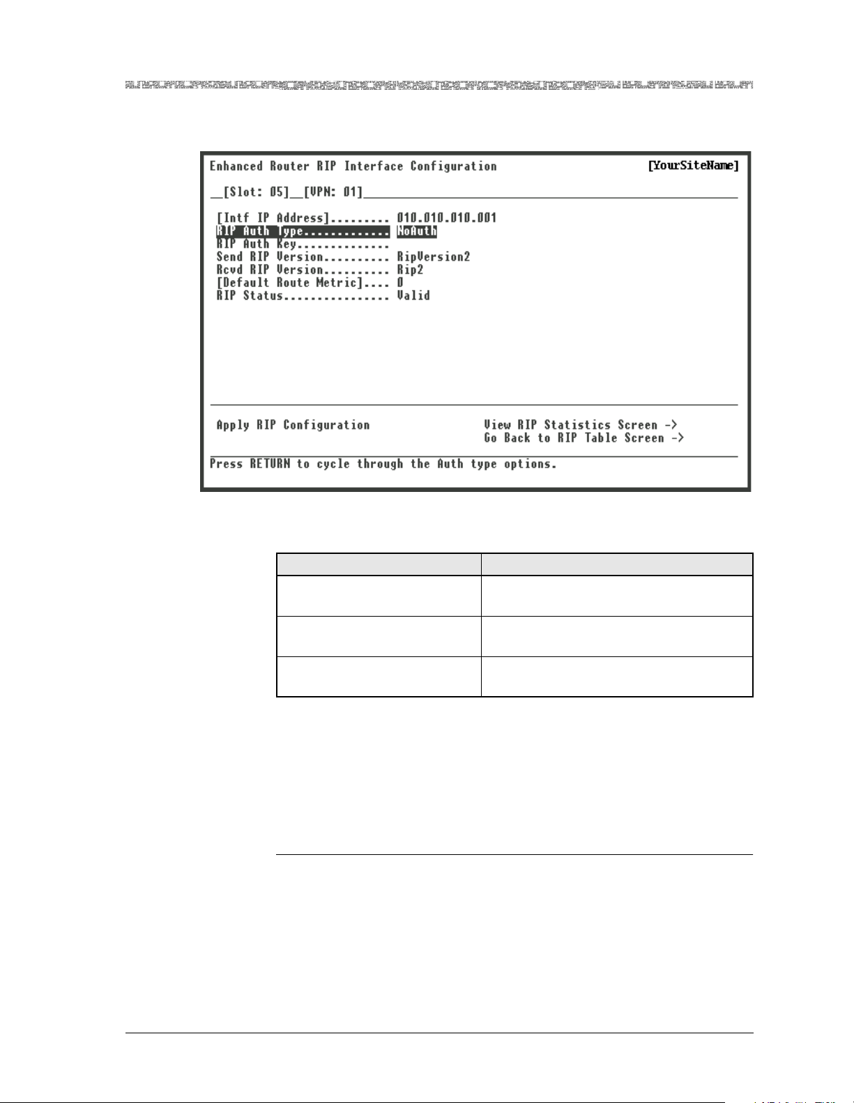
Chapter 3 Configuring VPNs Using the Console Interface
Viewing and Updating RIP Interfaces
The Enhanced Router RIP Interface Configuration window is displayed
(see Figure 3-14).
Figure 3-14. Enhanced Router RIP Interface Configuration Window
The commands in this window have the following functions:
Command Function
Apply RIP Configuration Creates a new RIP interface or modifies
this existing RIP interface.
View RIP Statistics Screen Displays the Enhanced Router RIP Inter-
face Statistics window.
Go Back to RIP Table Screen Redisplays the Enhanced Router RIP
Interface Table window.
2 Enter the values for the fields on this window according to the informa-
tion provided in Table 3-10.
3 To apply the values for the fields, select the Apply RIP Configuration
command.
The interface is displayed in the Enhanced Router Interface Table win-
dow.
End
PacketStar® PSAX Enhanced Router Module User Guide, Issue1 Release9.1.0
255-700-614 3-35
Page 86

Chapter 3 Configuring VPNs Using the Console Interface
Viewing and Updating RIP Interfaces
Table 3-10. Enhanced Router RIP Interface Configuration Window Field Descriptions
Field Name Field Values Description
[Intf IP Address] Default: N/A
Range:
Format: IP Address
Indicates the IP address of the RIP interface on
the indicated subnet from the IP Netw or k Intf
Addr field on the Enhanced Router Conf iguration
window.
Note: If RIP is enabled on an unnumbered interface, the IP address of the router ID will not be
shown; instead, the IfIndex value is displayed.
RIP Auth Type Default: NoAuth
Range: N/A
Indicates the type of authe n tication used on this
RIP interface .
Format: Predefin ed
NoAuth Indicates that authentication is not used on this
RIP interface .
SimplePassword Indicates that a simple password of up to 16
ASCII characters (specified in the RIP Auth Key
field) is used for authentication on this RIP inter-
face. When RIP updates packets to other routers,
it sends this password.
Md5 This value is not currently supported.
RIP Auth Key Default: N/A
Range:
Format:
Indicates the authentication key to be used. This
field will be used by the Enhanced Router mod-
ule when the value in the RIP Auth Type field is
set to a value other than NoAuth. Leave this
field blank if you have selected NoAuth in the
RIP Auth Type field.
PacketStar® PSAX Enhanced Router Module User Guide, Issue 1 Release 9.1.0
3-36 255-700-614
Page 87

Chapter 3 Configuring VPNs Using the Console Interface
Viewing and Updating RIP Interfaces
Table 3-10. Enhanced Router RIP Interface Configuration Window Field Descriptions (Continued)
Field Name Field Values Description
Send RIP Version Default: RipVersion
1
Range: N/A
Format: Predefin ed
Indicates whether the Enhanced Router module
will send RIP packets on this RIP interface, and if
so, the type of RIP packets.
Note: If the value in the RIP Auth Type field is set
to a value other than NoAuth and you modify
the value in the Send RIP Version field, you must
re-enter the authent icatio n key. Otherwise, a RIP
authentication failure will occur on the remote
endpoint: the module returns a blank value for
the Auth Key field.
DoNotSend Indicates that the module will not send RIP pack-
ets on this RIP interface.
RipVersion1 Indicates that th e mo dul e wi ll s end RI P v er si o n 1
and RFC 1058-compliant RIP packets on this RIP
interface.
Rip1Compatible Indicates that the module will broadcast RIP ver-
sion 2 packets on this RIP interface.
RipVersion2 Indicates that the module will multicast RIP ver-
sion 2 packets on this RIP interface.
Rcvd RIP Version Default: Rip2
Range: N/A
Format: Predefin ed
Indicates whether RIP packets are accepted by
the Enhanced Router module on this RIP interface, and if so, the type of RIP packets.
Note: If the value in the RIP Auth Type field is set
to a value other than NoAuth and you modify
the value in the Send RIP Version field, you must
re-enter the authent icatio n key. Otherwise, a RIP
authentication failure will occur on the remote
endpoint: the module returns a blank value for
the Auth Key field.
DoNotReceive Indicates that the module will not accept RIP
packets on t his RIP interface.
Rip2 Indicates that the module will accept multicast
RIP version 2 packets on this RIP interface.
Rip1 Indicates that the module will accept RIP version
1 and RFC 1058-compliant RIP packets on this
RIP interface .
Rip1OrRip2 Indicates that the module will accept multicast
packets on t his RIP interface.
[Default Route
Metric]
Default: 0
Range: 0–15
Format: Numeric
Displays the metric to be used for the default
route entry in RIP updates created on this RIP
interface. When the value for this field is set to 0,
no default route will be created.
PacketStar® PSAX Enhanced Router Module User Guide, Issue1 Release9.1.0
255-700-614 3-37
Page 88

Chapter 3 Configuring VPNs Using the Console Interface
Viewing and Updating RIP Interfaces
Table 3-10. Enhanced Router RIP Interface Configuration Window Field Descriptions (Continued)
Field Name Field Values Description
Rip Status Default: Valid
Range: N/A
Indicates whether this RIP inte rfac e exists on this
IP network interface.
Format: Predefin ed
Valid Indicates that this interface exists.
Invalid Indicates that this interface will not accept RIP
packets.
Deleting an RIP Interface
Once an RIP interface is created, it will remain present until it is deleted. RIP
interfaces are automatically populated after the IP interface is created, if RIP
is enabled on the VPN.
Perform the following procedure to delete an RIP interface.
Deleting an Interface
Begin
1 On the Enhanced Router RIP Interface Configuration window, select
Invalid in the RIP Status field.
2 Select the Apply RIP Configu r atio n command.
The following message appears at the bottom of the window:
Are you sure you want to delete this RIP Interface? y/n
3 Type Y.
The RIP interface is deleted. The associated IP interface and connections
are not deleted.
End
Viewing RIP Interface Statistics
Perform the following procedure to view the statistics for this RIP interface.
Begin
1 Go to the Enhanced Router Interface Configuration window.
2 Select the View RIP Interface Statistics Screen command.
PacketStar® PSAX Enhanced Router Module User Guide, Issue 1 Release 9.1.0
3-38 255-700-614
Page 89
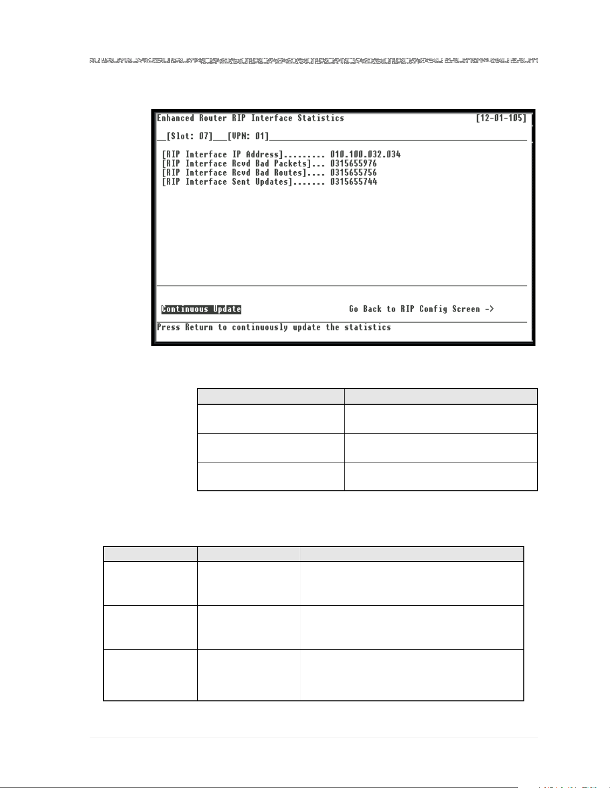
Chapter 3 Configuring VPNs Using the Console Interface
Viewing and Updating RIP Interfaces
The Enhanced Router RIP Interface Statistics window is displayed (see
Figure 3-15).
Figure 3-15. Enhanced Router RIP Interface Statistics Window
The commands in this window have the following functions:
Command Function
Continuous Update Updates the values constantly. Press any
key to stop the update.
Reset Statistics Sets the values on this window to their
default values.
Go Back to RIP Config
Screen
Redisplays the Enhanced Route r RIP
Interface Configuration window.
The display-only fields in this window are described in Table 3-11.
Table 3-11. Enhanced Router Module RIP Interface Statistics Window Field Descriptions
Field Name Field Values Description
[RIP2 Intf IP
Address]
Default: 0
Range: N/A
Displays the IP address of this system on the indicated subnet.
Format: IP address
RIP2 Intf Rcvd Bad
Packets
RIP2 Intf Rcvd Bad
Routes
Default: N/A
Range: N/A
Format: Numeric
Default: N/A
Range: N/A
Format: Numeric
Displays the number of RIP response packets
received by the RIP process which were subsequently discarded for any reason.
Displays the number of bad routes, in valid RIP
packets, which were ignored for any reason (for
example, an unknown address family, or invalid
metric).
PacketStar® PSAX Enhanced Router Module User Guide, Issue1 Release9.1.0
255-700-614 3-39
Page 90
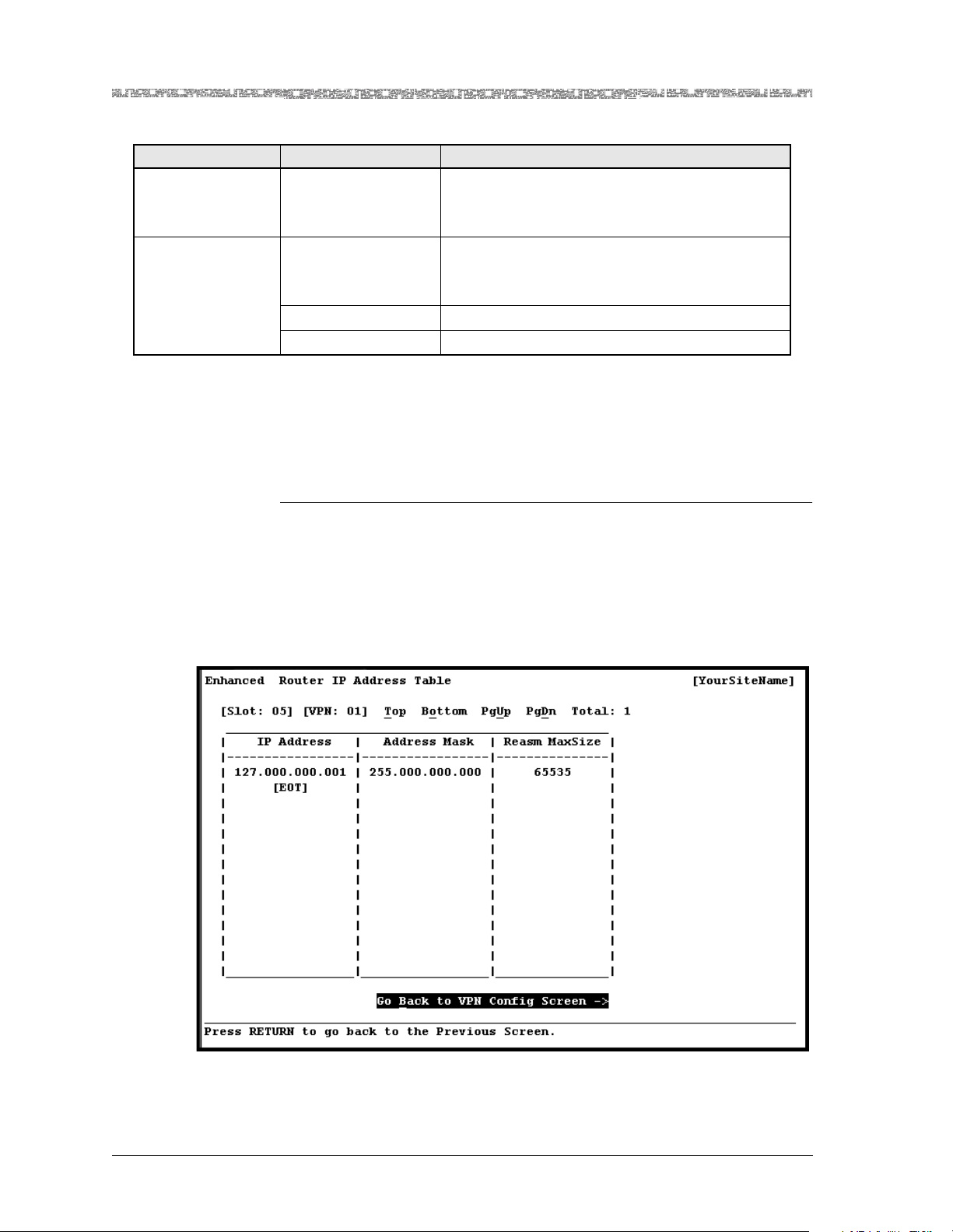
Chapter 3 Configuring VPNs Using the Console Interface
Viewing IP Addresses
Table 3-11. Enhanced Router Module RIP Interface Statistics Window Field Descriptions (Continued)
Field Name Field Values Description
RIP2 Intf Sent
Updates
Default: N/A
Range: N/A
Displays the number of triggered RIP updates
actually sent on this interface.
Format: Numeric
RIP Intf Stats Status Default: Valid
Range: N/A
Indicates whether this RIP inte rfac e exists on this
IP network interface.
Format: Predefin ed
Valid Indicates that this interface exists.
Invalid Indicates that this interface has been deleted.
Viewing IP Addresses
Perform the following procedure to view IP addresses.
Begin
1 Go to the Enhanced Router IP Address Table window.
2 Select the View IP Address Table command.
The Enhanced Router IP Address Table window is displayed (see
Figure 3-16).
Figure 3-16. Enhanced Router IP Address Table Window
The command in this window has the following functions:
PacketStar® PSAX Enhanced Router Module User Guide, Issue 1 Release 9.1.0
3-40 255-700-614
Page 91
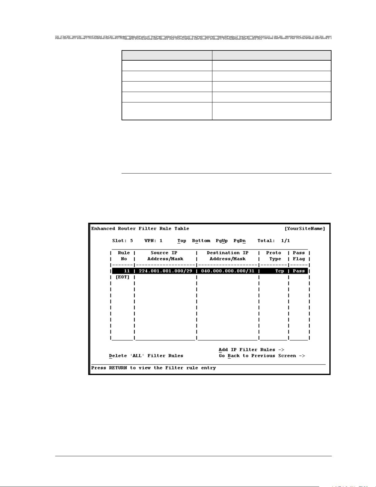
Chapter 3 Configuring VPNs Using the Console Interface
Configuring IP Filter Rules
Command Function
Top Displays the first page of the table.
Bottom Displays the last page of the table.
PgUp Displays the previous page of the table.
PgDown Displays the next page of the table.
Go Back to VPN Config
Screen
Configuring IP Filter Rules
To configure and/or view IP filter rules, perform the following procedure.
Begin
1 On the Enhanced Router VPN Configuration window, select the View IP
Filter Table command.
The Enhanced Router Filter Rule Table window is displayed (see
Figure 3-17).
Redisplays the Enhanced Router V PN
Configuration window.
Figure 3-17. Enhanced Router Filter Rule Table Window
The commands in this window have the following functions:
PacketStar® PSAX Enhanced Router Module User Guide, Issue1 Release9.1.0
255-700-614 3-41
Page 92
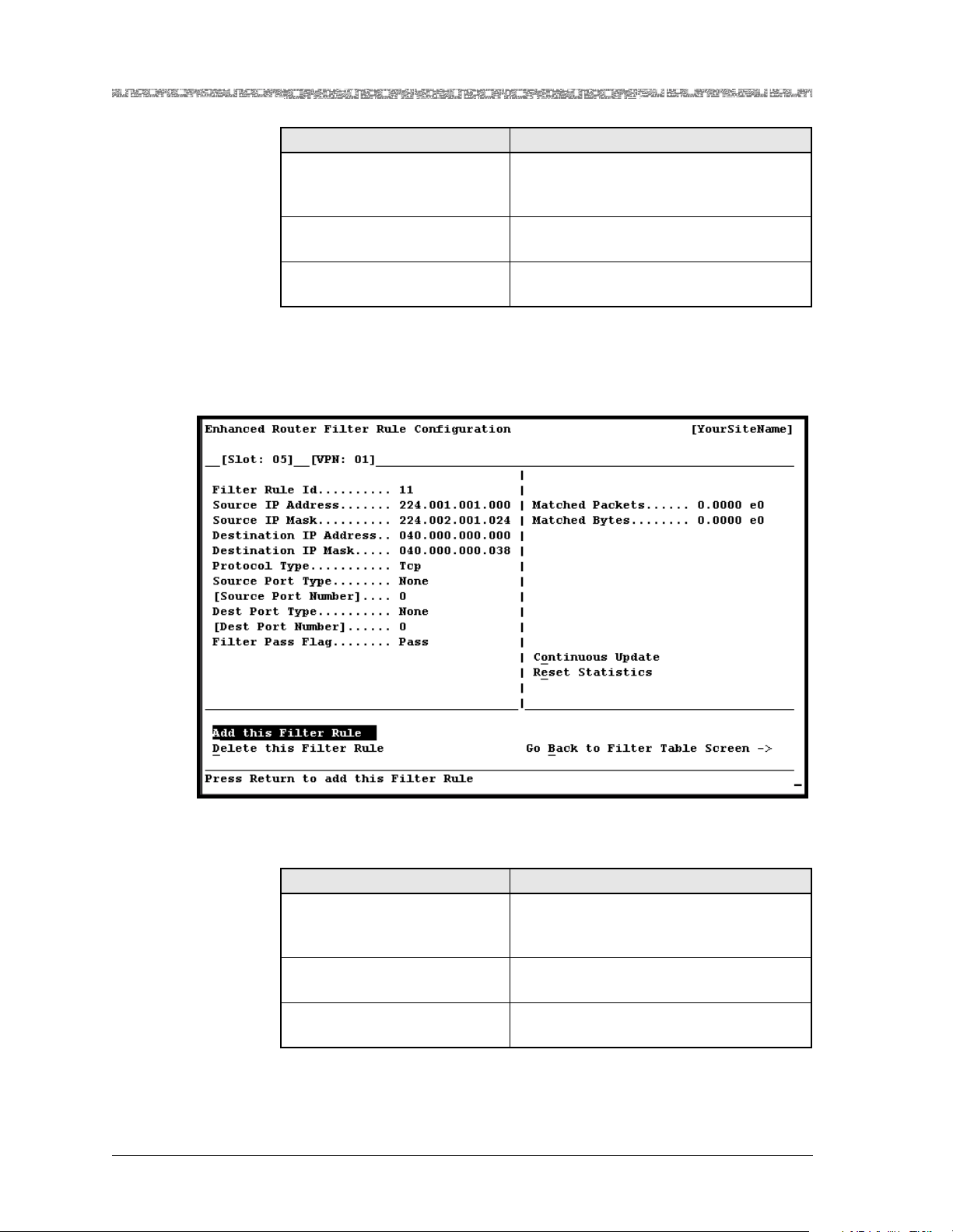
Chapter 3 Configuring VPNs Using the Console Interface
Configuring IP Filter Rules
Command Function
Delete ‘ALL’ Filter Rules Removes all filter rule entries from the
Add IP Filter Rules Displays the Enhanced Router Filter Rule
Go Back to Previous Screen Redisplays the Enhanced Router VPN
2 Select the Add IP Filter Rules command.
The Enhanced Router Filter Rule Configuration wind ow is displayed (see
Figure 3-18).
Enhanced Router Filter Rule Table window.
Configuration window.
Configuration window.
Figure 3-18. Enhanced Router Filter Rule Configuration Window
The commands in this window have the following functions:
Command Function
Continuous Update Allows the statistics values to update con-
tinuously. If you press any key or exit the
screen, the updating will stop.
Reset Statistics Resets the statistics on this window to
zero.
Add this Filter Rule Saves the filter rule entry to the Enhanced
Router Filter Rule Table window.
PacketStar® PSAX Enhanced Router Module User Guide, Issue 1 Release 9.1.0
3-42 255-700-614
Page 93

Chapter 3 Configuring VPNs Using the Console Interface
Command Function
Delete this Filter Rule Removes this filter rule entry from the
Enhanced Router Filter Rule Table window.
Go Back to Filter Table
Screen
Redisplays the Enhanced Router Filter
Rule Table window.
3 Select the values for the fields on this window from the values given in
Table 3-12.
4 To apply the values for the fields, select the Add this Filter Rule com-
mand.
5 Once the filter rule is added, you can view it in the Enhanced Router Fil-
ter Rule Table window by selecting the Go Back to Filter Table Screen
command.
End
Table 3-12. Enhanced Router Filter Rule Configuration Window Field Descriptions
Configuring IP Filter Rules
Field Name Field Values Description
Slot: Default: N/A
Range: Chassis
Displays the slot number where the Enhanced
Router module is installed in the PSAX chassis.
dependent
Format: Numeric
VPN: Default: N/A
Identifies the VPN where this filter rule resides.
Range: 1–6
Format: Numeric
Filter Rule Id Default: 0
Range: 1–65535
Format: Numeric
Displays a unique identifier for this filter. Smaller
filter identifiers have higher priority than larger
filter identifiers. If the rules are dynamic in
nature, it is recommended that you add filter
identifiers such as 100, 200, and so on, so that fil-
ters can be inserted in between these values.
Source IP Address Default: 0
Range: N/A
Format: IP Address
Indicates the IP address to match against the
packet's source IP address. If you are not con-
cerned with identifying the source of the packets
that reach the Enhanced Router module, this
value should be set to 0.
Source IP Mask Default: 0
Range: N/A
Format: IP Address
Indicates the IP mask for the matching of the
source IP addres s. If yo u are not concern ed wit h
identifying the source of the packets that reach
the Enhanced Router module, this value should
be set to 0.
Destination IP
Address
Default: 0
Range: N/A
Format: IP Address
Indicates the IP address to match against the
packet's destination IP address. If you are not
concerned with identifying the de st inatio n of the
packets that are passed through the Enhanced
Router module, this value should be set to 0.
PacketStar® PSAX Enhanced Router Module User Guide, Issue1 Release9.1.0
255-700-614 3-43
Page 94

Chapter 3 Configuring VPNs Using the Console Interface
Configuring IP Filter Rules
Table 3-12. Enhanced Router Filter Rule Configuration Window Field Descriptions (Continued)
Field Name Field Values Description
Destinatio n I P Ma sk Default: 0
Range: N/A
Format: IP Address
Indicates the IP mask for the ma tching o f the d estination IP address. If you are not concerned with
identifying the destination of the packets that are
passed through the Enhanced Router module),
this value should be set to 0.
Protocol Type Default: NoProto
Range: N/A
Format: Predefin ed
Indicates the type of IP protocol to match against
the packet’s protocol. If you are not concerned
with identifying the protocol of the packets that
are passed through the Enhanced R outer module,
this value should be set to NoProto.
NoProto Indicates that no protocol type is used on this fil-
ter rule.
Tcp Indicates that packets with the TCP protocol type
are used on this filter rule.
Udp Indicates that packets with the UDP pro tocol type
are used on this filter rule.
Other Indicates that the protocol used in this filter rule
are a protocol other than TCP or UDP. When you
select this field value, the other field values on
this window are not displayed.
[Source Port Type] D e fault: None
Range: N/A
Format: Predefin ed
Indicates the type of port numbers used for this
filter rule. If this field is not used, its value should
be set to None. TCP and UDP port numbers are
typically assigned to services. Well known port
numbers are listed in RFC 1700.
Note: This field is display-only when the Protocol
Type is set to NoProto.
None Indicates that this filter rule does not check the
source port.
Assigned-Ports Indicates that the well known (0–1,023) and Reg-
istered Ports (1,024–49,151) are used for this filter rule.
Private-Port Indicates that the dynamic and/or private Port s
(49,152–65,535) are used for this filter rule.
Specific-Port Indicates that a user-defined port numbe r is used
for this filter rule.
[Source Port Number]
Default: 0
Range: 0–65535
Format: Numeric
Indicates the specific port number when the field
value in the Source Port Type field is Specific-
Port.
Note: This field is display-only except when the
[Source Port Type] field is Specific-Port.
PacketStar® PSAX Enhanced Router Module User Guide, Issue 1 Release 9.1.0
3-44 255-700-614
Page 95

Chapter 3 Configuring VPNs Using the Console Interface
Configuring IP Filter Rules
Table 3-12. Enhanced Router Filter Rule Configuration Window Field Descriptions (Continued)
Field Name Field Values Description
[Dest Port Type] Default: None
Range: N/A
Format: Predefin ed
Indicates the type of port numbers used for this
filter rule. If this field is not used, its value should
be set to None.
TCP and UDP port numbers are typically assigned
to services. Well-known port numbers are listed
in RFC 1700.
Note: This field is display-only when the Protocol
Type is set to NoProto.
None Indicates that this filter rule does not check the
destination port.
Assigned-Ports Indicates that the well known (0–1,023) and Reg-
istered Ports (1,024–49,151) are used for this fil-
ter rule.
Private-Port Indicates that the dynamic and/or private Ports
(49,152–65,535) are used for this filter rule.
Specific-Port Indicates that a user-def ined po rt numbe r i s used
for this filter rule.
[Dest Port Number] Default: 0
Range: 0–65535
Format: Numeric
Indicates the specific port number when the field
value in the [Dest Port Type] field is Specific-
Port.
Note: This field is display-only except when the
the [Dest Port Type] field is Specific-Port.
PacketStar® PSAX Enhanced Router Module User Guide, Issue1 Release9.1.0
255-700-614 3-45
Page 96

Chapter 3 Configuring VPNs Using the Console Interface
Configuring Static IP Routes
Table 3-12. Enhanced Router Filter Rule Configuration Window Field Descriptions (Continued)
Field Name Field Values Description
Filter Pass Flag Default: Drop
Range: N/A
Format: Predefin ed
Drop Indicates the drop action filter rule.
Pass Indicates the pass action filter rule.
Matched Packets
(display only)
Matched Bytes
(display only)
Default: N/A
Range: N/A
Format: Scientific
notation
Default: N/A
Range: N/A
Format: Scientific
notation
Indicates the action to be taken on this module
for each filter rule (drop or pass).
If you want a default action of Drop, insert a rule
with a maximum value in the Filter Rule Id field
(for example, 65535), change all the numeric
field values on the Enhanced Router Filter Rule
Configuration window to their default values,
and set the Filter Pass Flag field to Drop.
If you want a default action of Pass, insert a rule
with a maximum value in the Filter Rule Id field
(for example, 65535), change all the numeric
field values on the Enhanced Router Filter Rule
Configuration window to their default values,
and set the Filter Pass Flag field to Pass.
Displays the number of packets matching this
rule.
Displays the number of bytes matching this rule.
Configuring Static IP Routes
Accessing the IP Route Table
To configure and/or view static IP routes, perform the following procedure.
Begin
1 On the Enhanced Router VPN Configuration window, select the View
Route Table command.
PacketStar® PSAX Enhanced Router Module User Guide, Issue 1 Release 9.1.0
3-46 255-700-614
Page 97
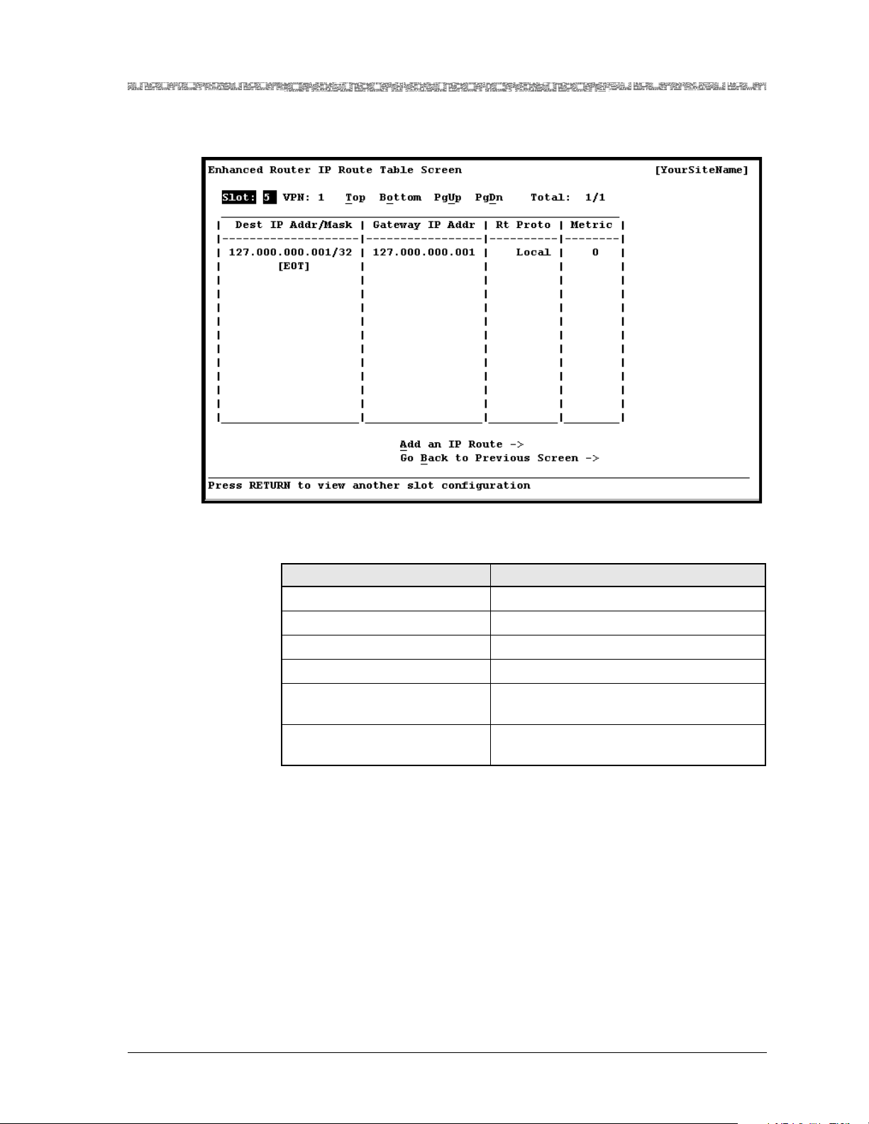
Chapter 3 Configuring VPNs Using the Console Interface
Configuring Static IP Routes
The Enhanced Router IP Route Table window is displayed (see
Figure 3-19).
Figure 3-19. IP Route Table Window
The commands in this window has the following functions:
Command Function
Top Displays the first page of the table.
Bottom Displays the last page of the table.
PgUp Displays the previous page of the table.
PgDown Displays the next page of the table.
Add an IP Route Displays the Enhanced Router IP Route
Configuration window.
Go Back to Previous Screen Redisplays the Enhanced Router VPN
Configuration window.
2 Select the Add an IP Route command.
PacketStar® PSAX Enhanced Router Module User Guide, Issue1 Release9.1.0
255-700-614 3-47
Page 98
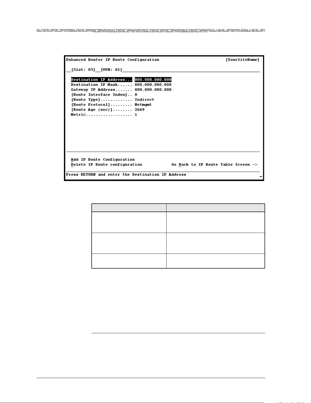
Chapter 3 Configuring VPNs Using the Console Interface
d
Configuring Static IP Routes
The Enhanced Router IP Route Configuration window is displayed (see
Figure 3-20).
Figure 3-20. Enhanced Router IP Route Configuration Window
The commands in this window have the following functions:
Command Function
Add IP Route Configuration Adds this destination IP address (ro ute ) t o
the Enhanced Router IP Route Table window.
Delete IP Route Configuration
Removes this destination IP address
(route) from the Enhanced Router IP
Route Table window.
Go Back to IP Route Table
Screen
Redisplays the Enhanced Router IP Route
Table window.
3 Select the values for the fields on this window from the values given in
Table 3-13.
4 To apply the values for the fields, select the Add IP Route command.
5 To bring the static IP route into service, select the Bring the IP Route
Into Service command.
The value InService is displayed in the [Admin Status] field.
En
PacketStar® PSAX Enhanced Router Module User Guide, Issue 1 Release 9.1.0
3-48 255-700-614
Page 99

Chapter 3 Configuring VPNs Using the Console Interface
Configuring Static IP Routes
Table 3-13. Enhanced Router IP Route Configuration Window Field Descriptions
Field Name Field Values Description
Note: You cannot change any fields on this window for an existing IP static route configura-
tion if Local or RIP was previously selected and applied in the Route Protocol field. You also
cannot change any fields on this window for an existing non-static route.
[Slot: ] Default: N/A
Range: Varies
Displays the slot number where the Enhanced
Router module is installed in the PSAX chassis.
depending on chassis
type
Format: Numeric
[VPN: ] Default: N/A
Identifies the VPN where this IP route resides.
Range: 1–6
Format: Numeric
Destination IP
Address
Default: N/A
Range: N/A
Format: IP Address
Indicates the destination IP address of this route.
Note: This field is display-only when viewing or
updating an existing IP static route or non-static
route. You can add additional routes to the same
destination IP address, by changing the Gateway
IP Address and Metric fields, but only the first
entry will be displayed on the window.
Destinatio n I P Ma sk Default: N/A
Range: N/A
Format: IP Address
Indicates the destination IP mask of this route.
Note: This field is display-only when viewing or
updating an existing IP static route or non-static
route.
Gateway IP Address Default: N/A
Range: N/A
Format: IP Address
Indicates the IP address of the next hop of this
route. The gateway address must be a remote
address on the same network as the IP interf ace
or the IP interface address (for interface-routing
capabilities).
[Route Interface
Index]
[Route Type] Default: Other
Default: 0
Range: N/A
Format: Numeric
Range: N/A
Displays the unique index value that identifies
the local interface through which the next ho p of
this route should be reached.
Displays the type of route. This field is display-
only when adding a static route.
Format: Predefin ed
Other Indicates that this route type is unspecified.
Invalid Indicates that this route invalidates the corre-
sponding entry in the IP Route Table. This route
is scheduled for deletion.
Direct Indicates that this route is directly connected to a
subnetwork.
Indirect Indicates that th is route is indirectly connected to
a remote host, network, or subnetwork.
PacketStar® PSAX Enhanced Router Module User Guide, Issue1 Release9.1.0
255-700-614 3-49
Page 100

Chapter 3 Configuring VPNs Using the Console Interface
Configuring Static IP Routes
Table 3-13. Enhanced Router IP Route Configuration Window Field Descriptions (Continued)
Field Name Field Values Description
[Route Protocol] Default:
Range: N/A
Format: Predefin ed
Displays the routing mechanism by which this
route was learned.
Note: You cannot change this IP route configuration after Local or RIP is selected and applied in
the Route Protocol field.
Other Indicates that the protocol is unspecified.
Local Indicates that the protocol is a local interface.
NetMgmt Indicates that the protocol is a static route.
ICMP Indicates that the protocol is the result of an
ICMP redirect.
Egp Indicates that the protocol is Exterior Gateway
Protocol, a dynamic routing protocol.
Ggp Indicates that the protocol is Gateway-to-Gate-
way Protocol, a dynamic routing protocol.
Hello Indicates that the protocol is FuzzBall HelloSpeak
Protocol, a dynamic routing protocol.
RIP Indicates that the protocol is Berkeley RIP or RIP
version 2, a dynamic routing protocol.
Is-is Indicates that the protocol is Dual IS-IS, a
dynamic routing protocol.
Es-is Indicates that the protocol is ISO 9542, a dynamic
routing protocol.
CiscoIgrp Indicates that the protocol is Cisco IGRP, a
dynamic routing protocol.
BbnSpfIgp Indicates that the protocol is BBN SPF IGP, a
dynamic routing protocol.
OSPF Indicates that the protocol is OSPF, a dynamic
routing protocol.
Bgp Indicates that the protocol is Border Gateway
Protocol, a dynamic routing protocol.
[Route Age (sec)] Default: 2669
Range:
Indicates the number of seconds since this route
was last created.
Format: Numeric
Metric Default: 0
Range: N/A
Format: Numeric
Indicates the primary routing metric for this
route, based on the value specified in the Route
Protocol field.
Note: Y ou canno t change thi s field va lue witho ut
changing any other field values on this window.
PacketStar® PSAX Enhanced Router Module User Guide, Issue 1 Release 9.1.0
3-50 255-700-614
 Loading...