

Page 1
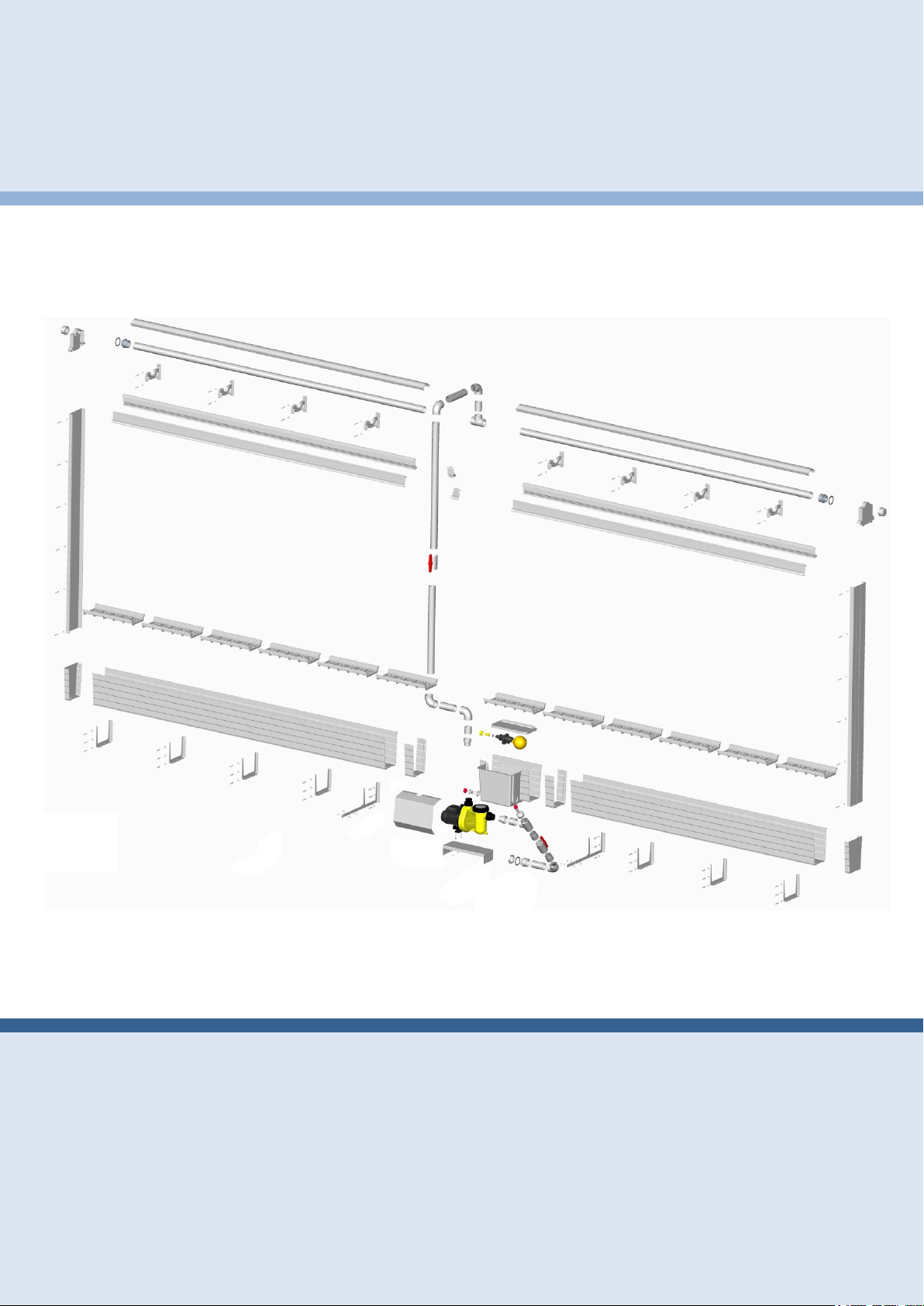
PAD-CLIMATE-SYSTEM
Assembly instruction and operators manual
Issue: November 2013
Version: 1.1.6
Page 2
Introduction
2
PAD- CLIMATE- SYSTEM
Assembly instruction and operators manual
Informations obout Producer:
LUBING Maschinenfabrik
GmbH & Co. KG
Lubingstraße 6
49406 Barnstorf
Tél.: +49 (0) 5442 / 9879 - 0
Fax: +49 (0) 5442 / 9879 - 33
• e-mail: [email protected]
• Internet: www.lubing.de
Informations obout service :
Page 3
Introduction
3
PAD- CLIMATE- SYSTEM
Assembly instruction and operators manual
Table of Contents
1. INTRODUCTION
B
RIEF DESCRIPTION OF LUBING PAD-CLIMATE-SYSTEMS ........................................... 4 1.1.
P
REFACE TO THE MANUAL .......................................................................................... 4 1.2.
2. GENERAL INFORMATION
W
ARNINGS AND SYMBOLS .......................................................................................... 5 2.1.
D
ESIGNATED USE ...................................................................................................... 6 2.2.
ENERAL SAFETY GUIDELINES - INTENDED USE ........................................................... 6 2.3.
G
O
BLIGATIONS ............................................................................................................ 7 2.4.
ARRANTY AND LIABILITY .......................................................................................... 7 2.5.
W
E
LECTRICAL SYSTEM ................................................................................................. 8 2.6.
3. ASSEMBLY
A
SSEMBLY INFORMATION ........................................................................................... 8 3.1.
P
AD LOCATION IN BUILDING ........................................................................................ 8 3.2.
SSEMBLY ORDER ..................................................................................................... 9 3.3.
A
S
PARE PARTS............................................................................................................ 9 3.4.
ECOMMENDED TOOLS .............................................................................................. 9 3.5.
R
I
NSTALLATION PROCEDURES ...................................................................................... 9 3.6.
SSEMBLING ............................................................................................................10 3.7.
A
3.7.1. Bracket for Watergutter ............................................................................................ 11
3.7.2. Watergutter ............................................................................................................... 12
3.7.3. Glued connections .................................................................................................... 12
3.7.4. Top Bracket .............................................................................................................. 14
3.7.5. Supply Unit ............................................................................................................... 14
3.7.6. Water Distribution Pipe ............................................................................................. 15
3.7.7. Pad Guide ................................................................................................................. 16
3.7.8. Covers ...................................................................................................................... 17
3.7.9. Deflector ................................................................................................................... 17
4. OPERATING INSTRUCTIONS
C
ONCEPT OF EVAPORATIVE COOLING ........................................................................18 4.1.
RIOR START UP ......................................................................................................18 4.2.
P
O
PERATING ..............................................................................................................19 4.3.
O REMOVE THE PAD GUIDE .....................................................................................20 4.4.
T
5. TECHNICAL DATA
C
ENTRIFUGAL-PUMP LUBING AQUA 11 ...................................................................21 5.1.
5.1.1. General technical data .............................................................................................. 21
5.1.2. 1 ~ 230 V / 50 Hz ...................................................................................................... 21
5.1.1. 1 ~ 230 V / 60 Hz ...................................................................................................... 21
5.1.2. 3 ~ Y/∆ 400 V / 50/60Hz ........................................................................................... 21
Page 4
Introduction
4
PAD- CLIMATE- SYSTEM
Assembly instruction and operators manual
1. Introduction
Brief description of LUBING Pad-Climate-Systems 1.1.
The LUBING Pad-Climate-System is a cooling- and humidification system for agricultural buildings for animal husbandry and for industrial complexes.
The system consists essentially of a pump which pumps water into a spray tube.
Through holes, water sprays against a Deflector. This distributes the water surface
covering over the Pads. The water goes on the one hand a part through the Pads
and the other part evaporated. The surplus water is caught in the Watergutter and
discharged partially and given on the other hand again to the pump.
Preface to the manual 1.2.
This manual facilitates is becoming acquainted with of the Pad-Climate-System and it
points out the intended use of the System. The manual contains important notes, as
the System is to be operated surely, properly and economically. Their attention helps
to avoid dangers to decrease repair costs and down-times and to increase the reliability and the life span of the System. The manual is to be supplemented around instructions due to existing national regulations for accident prevention and to environmental protection. The manual must be constantly at the place of work of the plant
available.
The manual is to be read and used from each person to, those assigned with work
with/on the System e.g.
• operation, including preparation, disturbance recovery in the work routine, removal
• of scraps, care, disposal of operating and auxiliary materials
• maintenance (maintenance, inspection, repair) and/or
• transport.
Beside the manual and in the user country and in the employment place valid obligatory regulations for accident prevention are to be considered also the recognized
specialized technical rules for security and professional working.
Page 5
General information
5
PAD- CLIMATE- SYSTEM
Assembly instruction and operators manual
2. General information
Warnings and symbols 2.1.
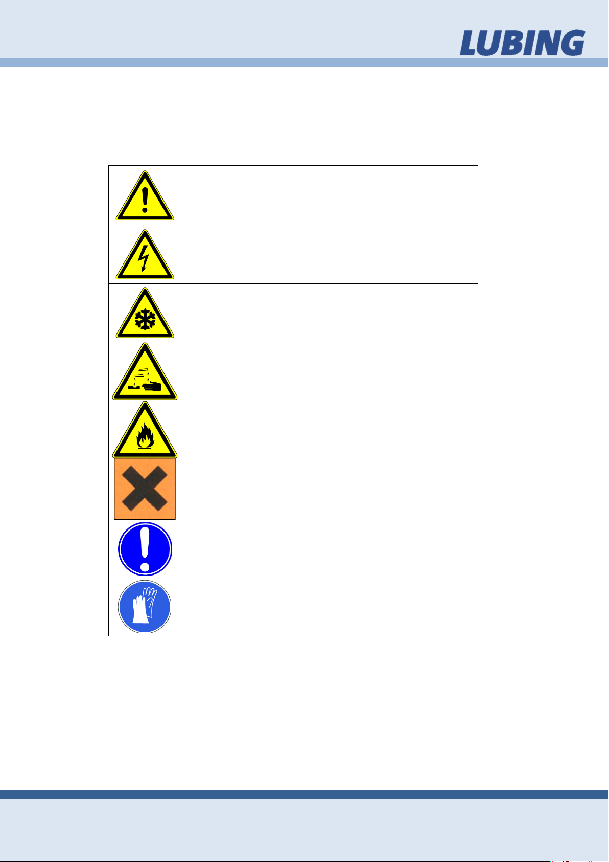
You will come across the following symbols while reading this manual.
Warns of general danger
Warns of dangerous electrical current
Warns of cold
Warns of corrosive substances
Warns of flammable substances
Substances detrimental to health
General mandatory sign
Mandatory sign indicating protective gloves
Page 6
General information
6
The relevant guidelines for the prevention of accidents as well as other generally recognised technical
safety and medical regulations for the workplace
must be observed.
PAD- CLIMATE- SYSTEM
Assembly instruction and operators manual
Designated use 2.2.
LUBING Pad-Climate-System is exclusively intended for cooling applications in stables.
Any other use shall not be regarded as proper. The manufacturer will not be liable for
any ensuing damage; this risk shall be borne by the user alone.
Designated use also includes:
• observing all of the information in the Operating Instructions and
• carry out all service and maintenance work as required.
LUBING Pad-Climate-Systems may only be operated, maintained and serviced by
personnel familiar with these measures and the potential dangers associated with the
system.
General safety guidelines - intended use 2.3.
These Operating Instructions include the most important information for operating the
Pad-Climate-Systems in a safe manner.
Check that the safety and functional equipment works safely and correctly:
• prior start-up
• at the appropriate intervals
• after modifications or maintenance.
The specifications outlined by the water and energy utility companies must also be
observed.
The system is exclusively intended for cooling/air-conditioning. Another use, like e.g.
for pumping other liquids than water is considered than not intended. For damage resulting from this the manufacturer/supplier is not responsible. The risk carries alone
the user.
To the intended use also belongs the attention of the manual and the adherence to of
the inspection and maintenance conditions.
Page 7
General information
7
PAD- CLIMATE- SYSTEM
Assembly instruction and operators manual
Obligations 2.4.
Observe information in the Operating Instructions
A basic prerequisite for safe handling and smooth operation of this Pad-ClimateSystem is knowledge of the basic safety information and safety guidelines. These
Operating Instructions, and the safety instructions in particular, must be observed by
all persons working on the Pad-Climate-System. Furthermore, all regulations and
guidelines governing the prevention of accidents and applicable for the respective
site must also be observed.
The Pad-Climate-System may only be used as designated when it is in a safe technical state. Any problems which may impair safety must be remedied without delay.
Organisational measures:
All safety equipment must be examined at regular intervals.
Warranty and liability 2.5.
As a general rule, our “General Terms and Conditions Governing Sale and Supply”
shall apply.
Warranty and liability claims in the event of personal and material damage are excluded if they are attributable to one or more of the following causes:
• non-designated use of the Pad-Climate-system,
• improper fitting, commissioning, operation and service of the system,
• operation of the system despite defective safety equipment or safety and
protective equipment which has been fitted incorrectly or is non-functional,
• non-observance of the information in the Operating Instructions as regards
transport, storage, fitting, commissioning, operation, service and equipment
of the system,
• independent structural modifications to the system,
• poor supervision of components subject to wear,
• repairs carried out incorrectly,
• catastrophes caused by foreign bodies and forces majeures.
Page 8
Assembly
8
Always isolate the power supply before working on
PAD- CLIMATE- SYSTEM
Assembly instruction and operators manual
Electrical system 2.6.
the electrical system.
All tasks extending beyond the framework of system maintenance may only be carried out by qualified personnel.
Always isolate the power supply when working on the device and secure against unauthorised reactivation by another person. Examine electrical cables for visible damage prior to commissioning. Replace any damaged lines before putting the device into operation. Damaged or destroyed plug devices must be replaced by a qualified
electrician. Do not remove plugs from sockets by pulling the cable. Covering electrical components can give rise to heat concentration with high temperatures which can
in turn destroy the equipment and cause fires.
3. Assembly
Assembly information 3.1.
Please read the following pages carefully. The instructions in this manual apply for
various Pad-Climate-Systems. For this reason, we would ask you to select and apply
the sections which concern you.
When using this manual for LUBING standard versions, please note all alterations to
and/or deviations from the scope of your supply.
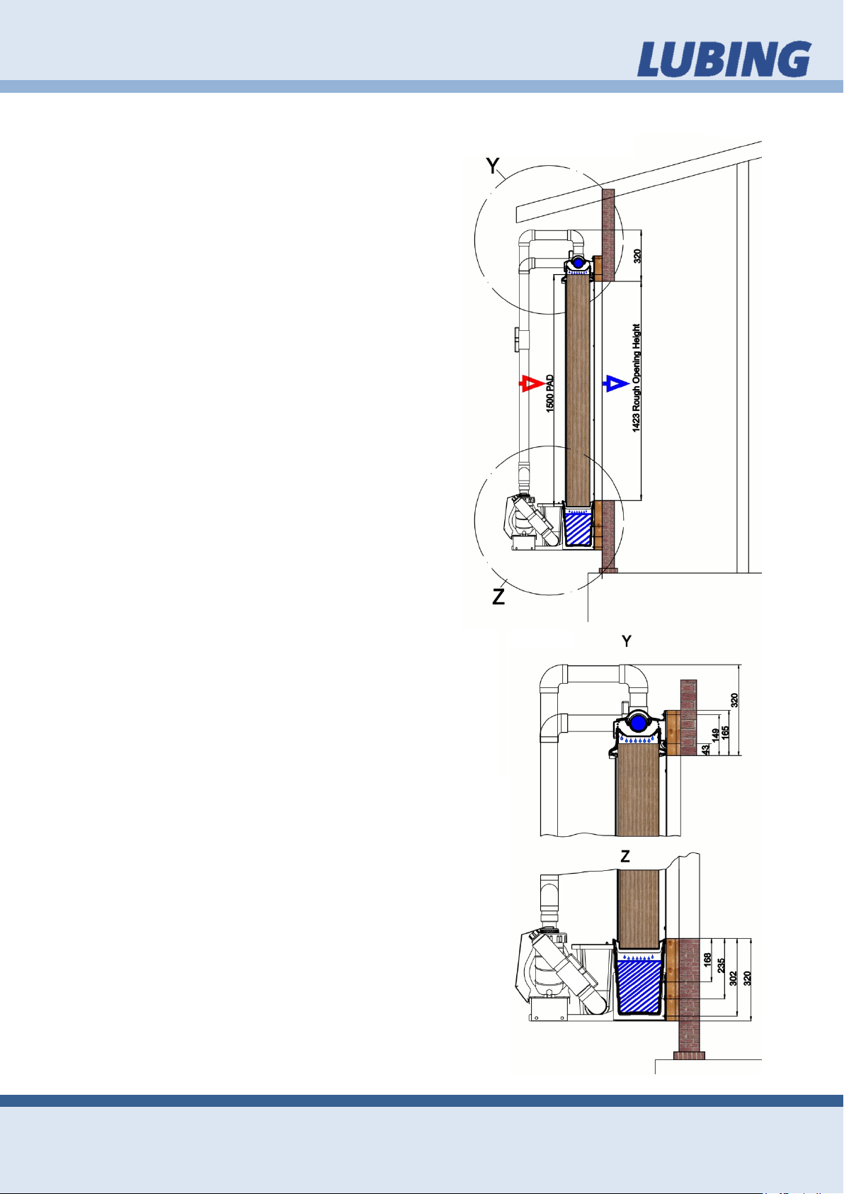
Pad location in building 3.2.
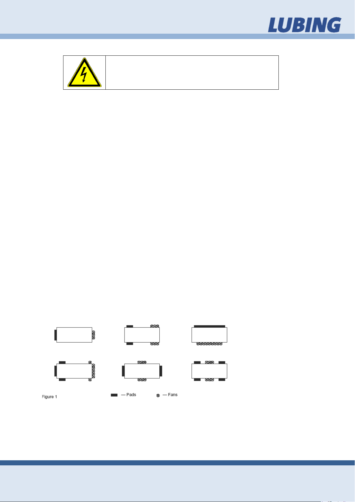
For poultry or livestock applications, the top of the Pads should be at the highest level at which cooling is desired. The Pads should be located on one end of the building
except in cases where the resulting air velocity exceeds the comfort level for the animals being housed. In these cases, the Pads should be on both sides at both ends
of the house, with the fans on both sides in the middle. See figure 1.
Many other designs are acceptable.
Page 9
Assembly
9
PAD- CLIMATE- SYSTEM
Assembly instruction and operators manual
Assembly order 3.3.
Use the Table of Contents to find the assembly section you require. The assembly
section describes the individual work steps
in the assembly order. Individual components are provided with position numbers in
the drawings. These position numbers can
also be found in the text.
Spare parts 3.4.
Spare parts for the Pad-Climate-System you
will find in the "Spare parts list for PadClimate-Systems"
This contains the exact name of the respective part and its item number, which we require in the event of spare parts being ordered. In order to procure electrical components, we require information on the power
supply, e.g. 230/400 V – 3 Ph. 50/60 Hz.
A current version is appended to these Assembly and Operating Instructions.
Recommended tools 3.5.
The following is a list of tools needed for the
installation of your LUBING Pad-ClimateSystem.
• Tape Measure
• Hack Saw
• Chalk Line
• Jigsaw or Circular Saw
• Level
• Screwdriver
Installation procedures 3.6.
This opening in the stable should have a
wood frame, all made of water-resistant
wood.
For systems 3m to 12m (10ft to 40ft) long,
the sump will be located at the end of the
system.
For systems 12m to 24m (40ft to 80ft) long,
the sump will be located at the center of the
system.
Page 10
Assembly
10
3.7.1.2
3.7.1.3
3.7.1.4
3.7.1.5
3.7.1.6
3.7.1.7
3.7.1.8
3.7.1.9
3.7.1.10
3.7.1.11
3.7.1.12
3.7.1.13
3.7.1.14
3.7.1.15
3.7.1.16
3.7.1.17
3.7.1.18
3.7.1.19
3.7.1.20
3.7.1.21
PAD- CLIMATE- SYSTEM
Assembly instruction and operators manual
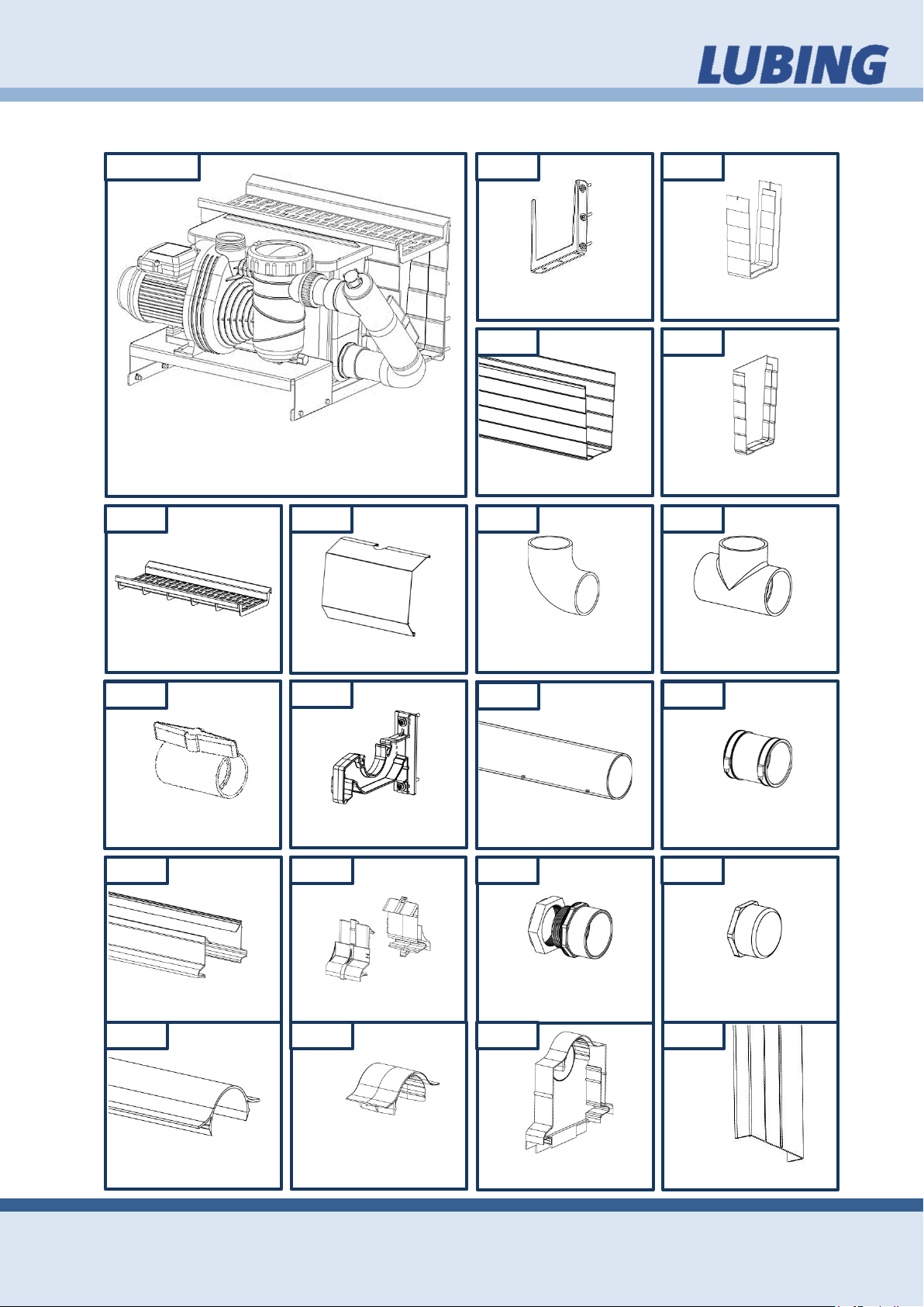
Assembling (Parts List) 3.7.
figure 3.7.1.1
Pad Support
Ball Valve
Pad Guide
Supply Unit
Pump Cover
Top Bracket
Pad Guide Coupler
Bracket for Watergutter
Watergutter
Elbow-Glue-Coupler
Water-Distribution-Pipe
(with holes)
Transition Piece
Coupling for Watergutter
Endcover for Watergutter
T-Glue-Coupler
Pipe Connector
Sealing Cap
Deflector
Deflector Coupling
Endcover for Deflector
Pad Cover
Page 11
Assembly
11
Fasten the Brackets in
Fasten each Brack-
with 3 fasteners
PAD- CLIMATE- SYSTEM
Assembly instruction and operators manual
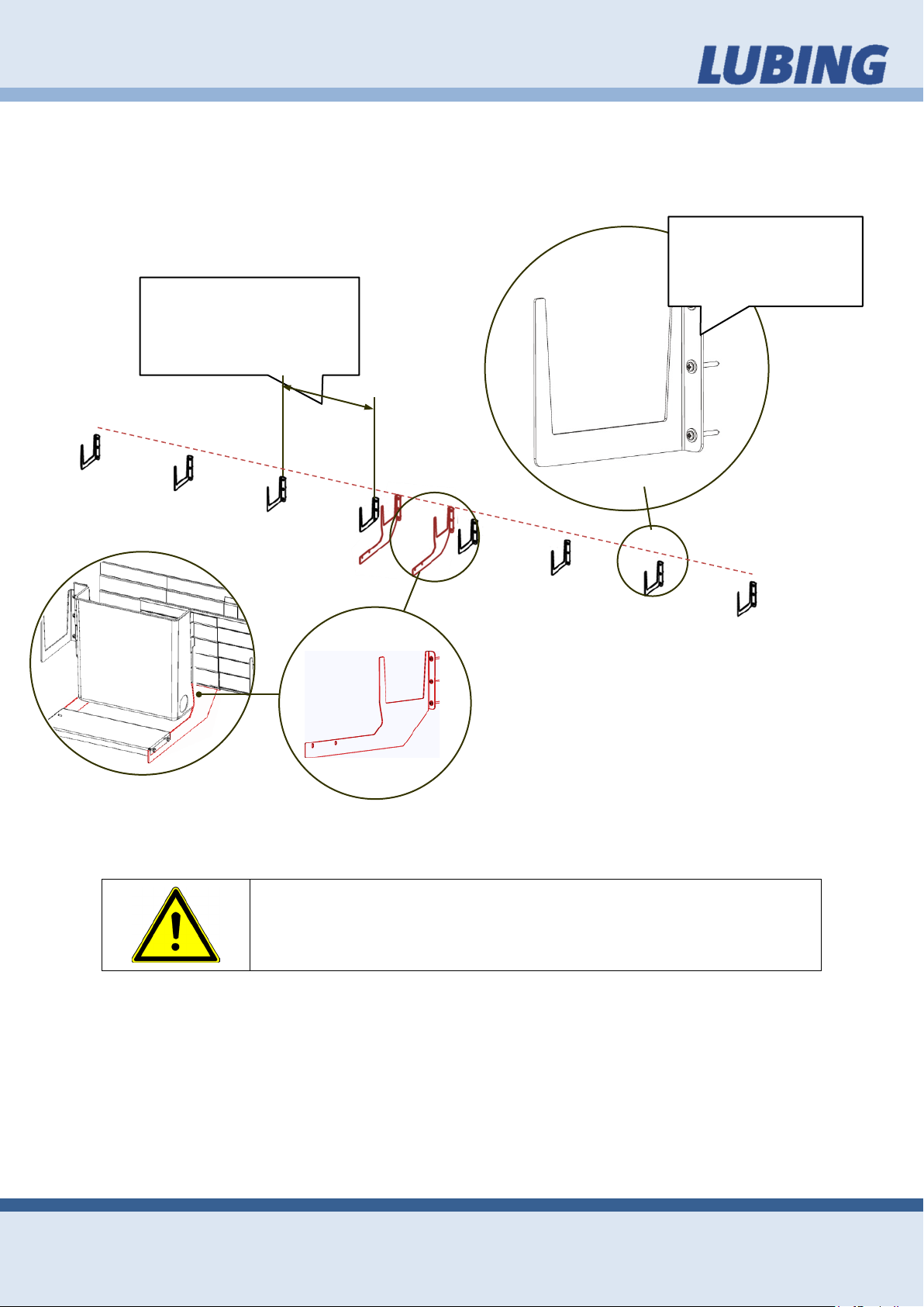
3.7.1. Bracket for Watergutter
The Brackets for the Watergutter are beginning fastened from the Supply Unit.
Measure off the two Brackets for the Supply Unit and those or the last Bracket. Then
mark with a chalk line the horizontal connection.
constant distances
from max 75 cm (30
The Supply Unit is already pre-assembled. The Brackets of the Supply Unit must also
been fasted in desired position.
et
and washers.
The uniform load of the ready for use system is 75 kg/m (165
lb/m)!
Page 12
Assembly
12
PAD- CLIMATE- SYSTEM
Assembly instruction and operators manual
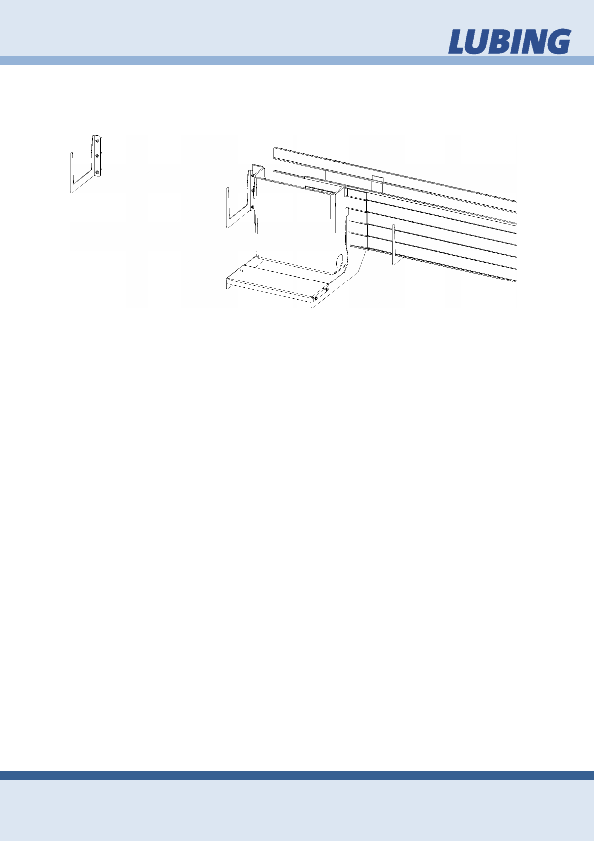
3.7.2. Watergutter
Beginn the glueing of the Watergutter and the Coupler for Watergutter with the housing of the Supply Unit up to the End Cover.
Consider the following points for a waterproof connection:
• sufficient adhesive quantity in the coupler particularly in the corners and at the
front of the Watergutter (Addehsive should get out from the coupler)
• Brisk processing (see 3.7.3 Glued connections)
• Accurate seat of the coupler and the Watergutter to each other (push Wa-
tergutter up to the stop into the coupler).
• During drying (24 hours) do not move the entire system any longer.
3.7.3. Glued connections
LUBING recommends "Tangit" adhesive for glued connections.
Many connection elements in the LUBING product range are designed as glued connections. Please observe the following manufacturer instructions in order to ensure
secure connections.
The pipe must be cut at a right angle and burred. The areas to be glued must be
clean and dry. Clean the ends of the pipe on the outside and the connecting elements on the inside using a cleaning agent (please check compatibility) and woven
felt. Always use new woven felt. The areas to be glued must be fully dry before applying the adhesive.
Push the pipe and connecting element without twisting until the limit stop and hold
tight for a few seconds until the glue has set. Immediately following joining, remove
superfluous glue with the woven felt as otherwise the pipe will be etched too strongly.
Owing to the fast setting features of the adhesive, the join parts must be pushed together within 4 minutes of applying the glue. The open period for Tangit depends on
the ambient temperature and/or film thickness.
Page 13
Assembly
13
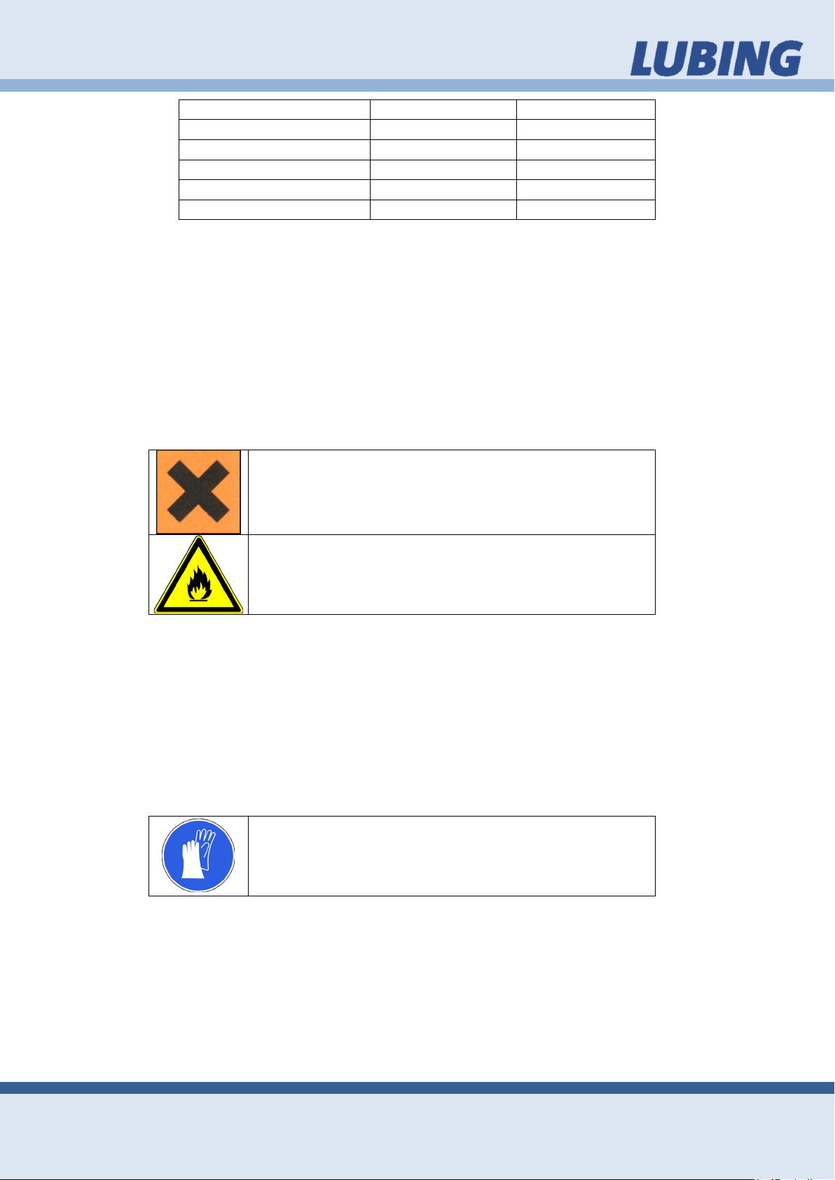
Ambient temperatue
Processing time
Film thickness
20 °C (68 °F)
approx. 4 min.
1 mm
25 °C (77 °F)
3 min.
1 mm
30 °C (86 °F)
2 min.
1 mm
40 °C (104 °F)
1 min.
1 mm
> 40 °C (>104 °F)
< 1 min.
1 mm
PAD- CLIMATE- SYSTEM
Assembly instruction and operators manual
Stress: Do not move the pipes for at least 5 minutes after gluing. At temperatures below 10°C (50 °F), this period is extended to a minimum of 15 minutes.
Pressure test: The pipes should not be filled nor should a pressure test be carried out
until 24 hours after the last gluing procedure. We recommend rinsing pipes and possibly even leaving them full of water if they are not put into operation immediately.
Please observe the protective measures described by the manufacturer.
Please also observe additional information in the data sheets and guidelines on the
prevention of accidents supplied by the professional associations, e.g. VBG 15, VBG
81, M017 and the Safety Data Sheets.
Tangit contains tetrahydrofurane and cyclohexanone.
Xi = irritable
Irritates the eyes and breathing apparatus
“Tangit” adhesive is highly flammable.
F = easily flammable!
Tangit is highly inflammable. Its solvent vapours are heavier than air and can form
explosive mixtures. For this reason, always ensure sufficient ventilation when processing, drying or gluing using Tangit. In workrooms and adjoining rooms: No smoking! No welding! No naked flames and avoid generating sparks! Prior to welding
work, accumulations of solvent vapours and explosive mixtures must be removed. Fill
pipelines with water, rinse well and blow through. Do not seal pipes during the drying
phase. Longer inhalation of these solvent vapours can lead to impaired health. Store
used woven felt in closed containers. If the substance comes into contact with the
eyes, rinse thoroughly with water and consult a doctor.
We recommend wearing protective gloves as a precaution for preventing contact with the skin.
Safety advice:
• Must be kept out of reach of children.
• Keep away from ignition sources – no smoking.
• Avoid contact with eyes.
• If ingested, consult a doctor and show packaging or label.
Page 14
Assembly
14
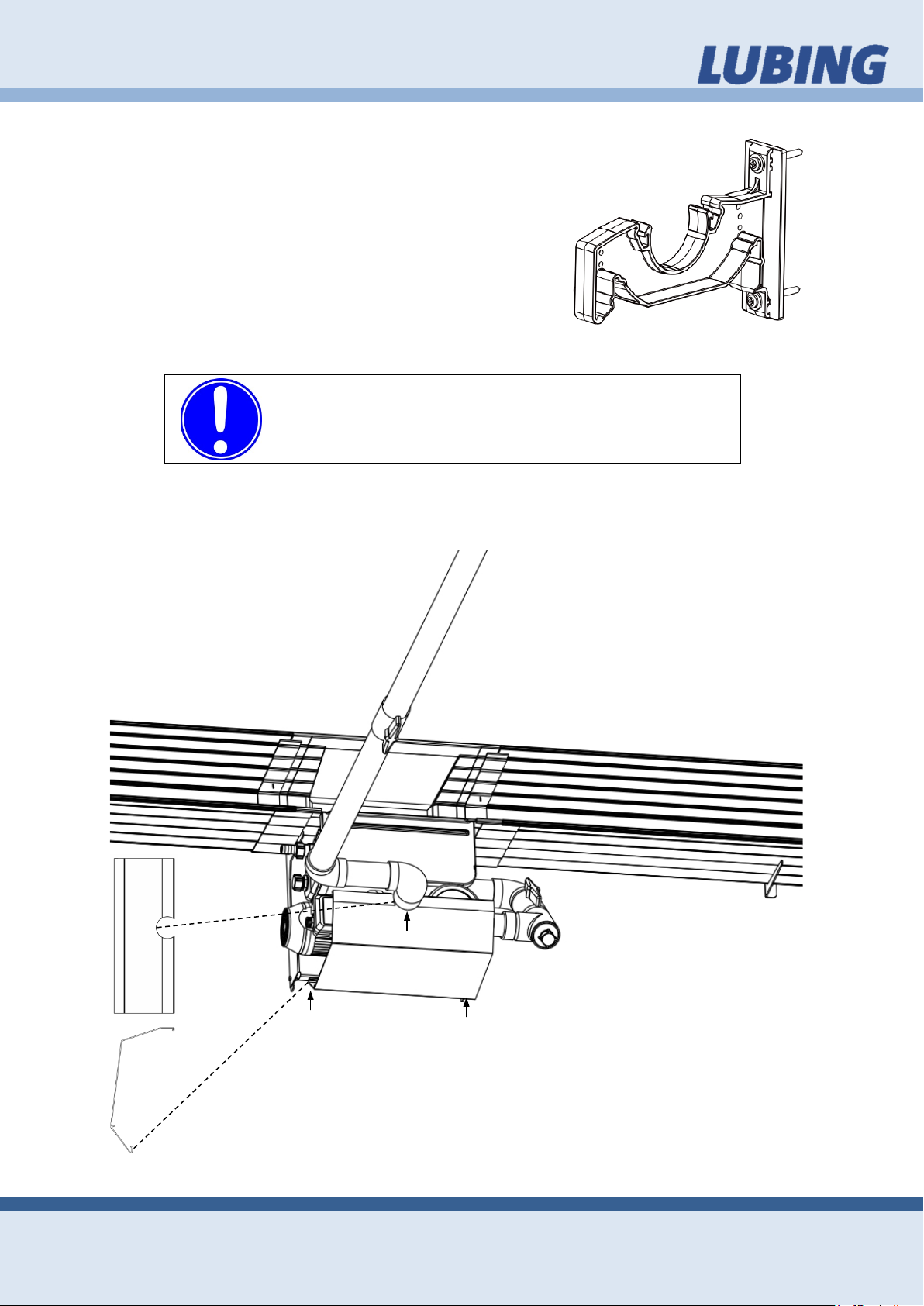
Pay attention to straight cuts of the pipe! Subsequent-
.
Contamination or splinters in the tubing system can
reduce the efficiency of the system or cause damage!
PAD- CLIMATE- SYSTEM
Assembly instruction and operators manual
3.7.4. Top Bracket
Measure off the place for the Top Bracket above the
Supply Unit. Masure off the place for the top Bracket
at the end(s). Then mark with a chalk line the horizontal connection between this points. Fasten the Top
Brackets in the distance from max 75 cm (30 in). Fasten each Top Bracket with two fasteners and washers.
3.7.5. Supply Unit
Build the piping between the Supply Unit and the Water Distribution Pipe.
ly, belve and if necessary clean the front of the pipes
Cut and stick together the whole piping system from the pump to the sump. Place the
Pump Cover on the Supply Unit for preventing dirt and splashing water to the Pump.
Consider the arrangement of the construction units as down in the sketch.
Fasten the float valve in the housing. The water connecting
should take place at a later time, so that the system is not
filled inadvertently.
Page 15
Assembly
15
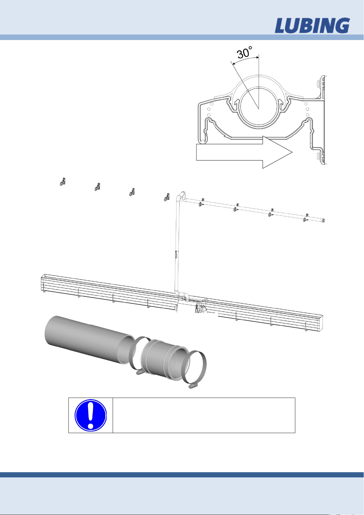
Pay attention to straight cuts of the pipe! Subsequent-
s.
Contamination or splinters in the tubing system can
reduce the efficiency of the system or cause damage!
Air flow
PAD- CLIMATE- SYSTEM
Assembly instruction and operators manual
3.7.6. Water Distribution Pipe
Begin with the sticking of the Water Distribution Pipe together with the T-Glue Coupler of the Supply Unit.
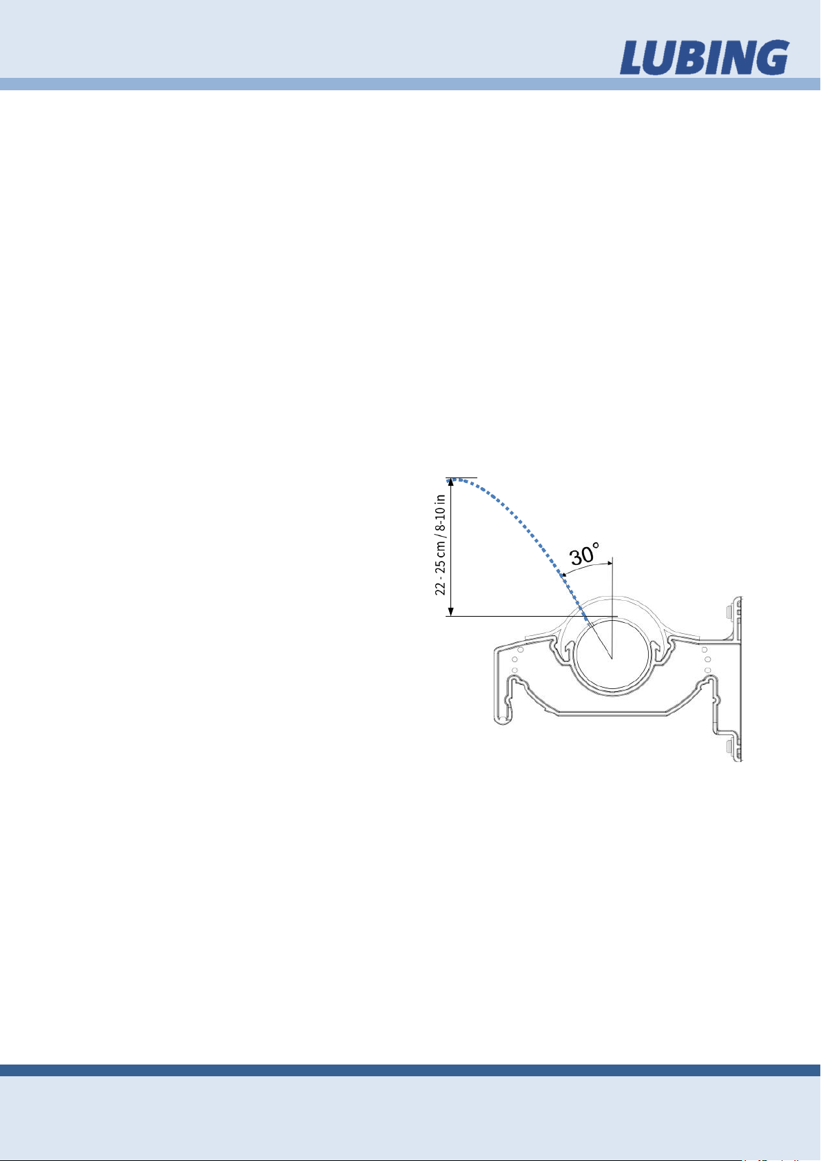
Note! The holes of the Water Distribution
Pipe must stand on 30 degrees with the air
flow from the outside.
ly, belve and if necessary clean the front of the pipe
Then connect with the pipeconnector and the clamps the
entire length.
Page 16
Assembly
16
PAD- CLIMATE- SYSTEM
Assembly instruction and operators manual
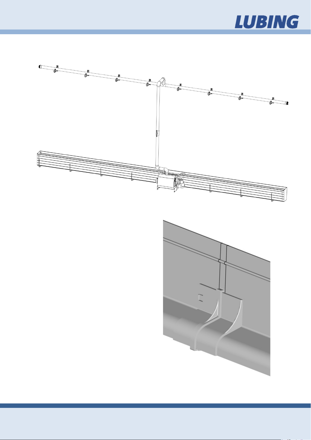
3.7.7. Pad Guide
Fasten the entire Pad Guide at the wall side through clip in.
Use the Pad Guide Coupler to connect
them over the whole length. For closing the
Pad Guide Coupler push slider to right and
clip in the left Pad Guide.
Page 17
Assembly
17
PAD- CLIMATE- SYSTEM
Assembly instruction and operators manual
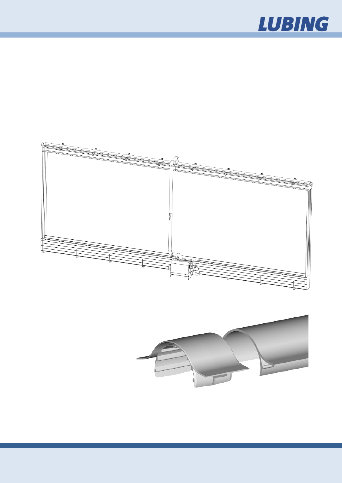
3.7.8. Covers
After the demanded drying time of all glue connections press the entire Pad Support
on the Watergutter. Fasten the Pad Covers with in each case 6 screws evenly over
the length distributed. For closing the Deflector section set up the Endcover for Deflector. Glue the Transition Piece at (to) the End(s) and screw the Sealing Cap on the
Transition Piece. Consider the drying time (24 hours)!
Push the first Pad into the Pad Cover. Put the other Pad onto the Pad Support. Fasten the Pad Guide for each middle element afterwards. Use to connect the Pad
Guide to the Pad Guide Coupler.
Push the last but one Pad into the Pad Cover. Then place the last Pad to the free position and fasten with the Pad Guide.
3.7.9. Deflector
Clip in the Deflector over the
whole length and use the
Deflector Couplings to connect them.
Page 18
Operating instructions
18
PAD- CLIMATE- SYSTEM
Assembly instruction and operators manual
4. Operating instructions
Concept of evaporative cooling 4.1.
To offset periods of extreme temperature that affect in-house environments and
therefore production, LUBING Pad-Climate-Systems are used with outstanding success. The benefits of evaporative Pad cooling are obtained by moving large quantities of air through water-saturated Pads. The resulting evaporation of water will lower
the air temperature. This method of cooling can provide dependable relief from heat
stresses in periods of hot weather. Suited for all geographic locations, a LUBING
Pad-Climate-System delivers the greatest economic benefits in areas where higher
temperatures during longer periods of time are normal.
LUBING Pad-Climate-System comprises the following components:
• Supply Unit
• Middle elements
• End kit
Prior start up 4.2.
• Connect the float valve to a suitable
water supply. WARNING! Check to
make sure that all locks are secured
before each use.
• If needed, adjust the floating valve
swimmer to the desired water level
by turning the adjusting screw.
• Please read through the “Original
Installation and Operating Manual”
carefully before you use the “AQUA
LUBING 11” pump for the first time.
Connect the pump as prescribed
from the manufacturer.
• Water quantity and distribution can
be adjusted by infinitely turning to
the Deflector. Adjust the holes of the
Water Distribution Pipe in an angle
of 30 degrees to the outside.
• To reach the right water quantity, adjust the Ball Valve to a water cullum
(which streams out of the holes) of 22-25 cm (8-10 in) height over the Water
Distribution Pipe.
Page 19
Operating instructions
19
The pH of the recirculated water must be maintained
between 6 and 9. A pH of 7 is neutral. A pH above 9
PAD- CLIMATE- SYSTEM
Assembly instruction and operators manual
Operating 4.3.
The durability of the Pads depends on its manufacturer and will last 5 or 6 years if
properly maintained. When the water is circulated and evaporated, the mineral content of the remaining water gets higher. To keep the mineral content within workable
levels, 5% to 10% of the circulated water must be bleeding off through the bleed off
opening. When mineral deposits are observed on the Pad, increase the amount of
bleed off.
Algae growth and water bacteria in the Pads must be controlled. The Pads are treated with a fungus resistant additive, but this does not completely prevent algae
growth. Treat the water with any of the chlorine algaecides (Calcium Hypoclorinates)
used for swimming pools, such as HTH or Pace. Tablet forms of these algaecides
are the most economical and best to use in the sump for slow release. Maintain the
sump water for recirculation at 1 ppm (part per million) chlorine. If a chlorine smell is
present, too much has been added. If any algae grows, tablets need to be added.
Water pH and chlorine levels should be checked weekly. Kits for testing pH and chlorine may be purchased at any swimming pool supply store. The life of your Pad depends on its proper maintenance.
Clean the filter at least once a week, more often if foreign materials are present in the
water system.
Flush pipe distribution system at least once a month. This is done by opening both
Ball Valves while the pump is running and allowing water to flow through and out of
the system.
Regulate your ventilation system so that the Pad system is turned off while all the
fans are still running. This will pull air through the Pads after the water is turned off,
allowing them to dry properly and killing any algae spores. Do not keep the Pads wet
around the clock as this will make the Pads soft.
When the evaporative Pad system is operating, check the Pads for dry spots. When
dry spots are observed, remove the Pad Cover and check the holes in the pipe.
Clean any stopped up holes with a wire until adequate water flows from each hole.
or below 6 will drastically reduce the life of the Pad.
DO NOT FLOW EXCESSIVE WATER ON THE PAD.
Page 20
Operating instructions
20
At the end of the evaporative cooling season, drain
system to avoid freezing
pletely drained, put anti-freeze in it.
PAD- CLIMATE- SYSTEM
Assembly instruction and operators manual
The Pads are more efficient if they have just enough water to keep them wet, but not
a stream of water cascading down the Pad.
Drain and clean the sump as necessary to remove any dirt or trash that it may have
accumulated.
the pump, sump and pipe
damage in cold weather. If the pump cannot be com-
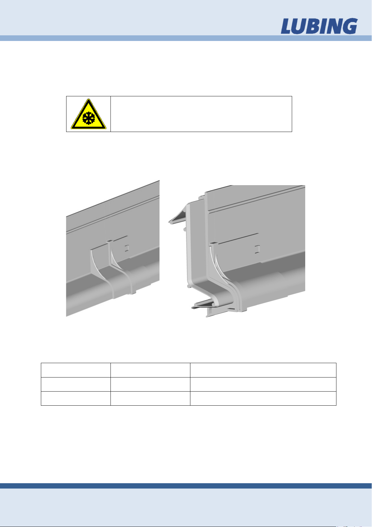
To remove the Pad Guide 4.4.
For opening the Pad Guide Coupler push slider to right and clip out the left Pad
Guide.
Malfunctions / Trouble shooting 4.5.
Problem Reason Solution
Pads too dry/wet system adjustment follow paragraph 4.2 “Prior start up”
flooded Watergutter Floating Valve adjustment adjust Floating Valve to a lower water level
clogged system dirt/foreign objects flush/clean system; see paragraph 4.3 “Operating”
Page 21
Technical Data
21
PAD- CLIMATE- SYSTEM
Assembly instruction and operators manual
5. Technical Data
Centrifugal-Pump LUBING AQUA 11 5.1.
5.1.1. General technical data
Type of motor enclosure: IP X4
Class of insulation: B
Motor speed approx.: 2840 rpm
Max. continuous sound
intensity level (A): ≤70 dB 1)
Max. water temperature: max. 60 °C | max. 140 °F
Max. housing pressure: max. 2,5 bar
Performance: 0,45 kW
5.1.2. 1 ~ 230 V / 50 Hz
Rated current: 3,20 A
Weight: 7,60 kg | 16,8 lb
Volumerate: 18 m³/h | 4755 gal/h 2)
5.1.1. 1 ~ 230 V / 60 Hz
Rated current: 3,20 A
Weight: 7,60 kg | 16,8 lb
Volumerate: 18 m³/h | 4755 gal/h 2)
5.1.2. 3 ~ Y/∆ 400 V / 50/60Hz
Rated current: 1,25/2,1500 A
Weight: 9,10 kg | 20,1 lb
Volumerate: 18 m³/h | 4755 gal/h 2)
1)
Measured with phonometer according to DIN 45635
2)
US liquid gallon
 Loading...