

Page 1

User’s Manual
Page 2

LTI 20/20 TruSpeed
User’s Manual
Part Number 0144805
Copyright Notice:
Information in this document is subject to change without notice and does not
represent a commitment on the part of Laser Technology Inc. No part of this
manual may be reproduced in any form or by any means, electronic or mechanical,
including photocopying, recording, or information storage and retrieval sys t ems, for
any purpose other than the purchaser’s personal use, without the express written
consent of Laser Technology, Inc.
Copyright © Laser Technology, Inc., 2007. All rights reserved.
Printed in the United States of America
First Edition— First Release: July 2007
First Edition— Second Release: September 2007
Trademarks:
TruSpeed is trademark of Laser Technology, Inc.
All other trademarks are the property of their respective owner.
Patents:
This product is covered by pending patent applications and/or
one or more of the following issued patents: 5,359,404
5,521,696
5,715,045
LTI Contact Information:
Laser Technology, Inc.
7070 S. Tucson Way
Centennial, CO 80112 USA
Phone: 1-303-649-1000
Fax: 1-303-649-9710
Web Site: www.lasertech.com
Page 3

LTI 20/20 TruSpeed User’s Manual Table of Contents
Page 1
LTI 20/20 TruSpeed
User’s Manual Table of Contents
Section #1 - Getting Started . . . . . . . . . . . . . . . . . . . . . . . . . . . . . . . . . 3
Unpacking Your TruSpeed . . . . . . . . . . . . . . . . . . . . . . . . . . . . . . . . . . . . 3
TruSpeed Basic Package . . . . . . . . . . . . . . . . . . . . . . . . . . . . . . . . . 3
Available Accessories . . . . . . . . . . . . . . . . . . . . . . . . . . . . . . . . . . . . 3
Important Safety Information . . . . . . . . . . . . . . . . . . . . . . . . . . . . . . . . . . 3
About the TruSpeed . . . . . . . . . . . . . . . . . . . . . . . . . . . . . . . . . . . . . . . . . 4
Sensors . . . . . . . . . . . . . . . . . . . . . . . . . . . . . . . . . . . . . . . . . . . . . . . 5
LCD Screen . . . . . . . . . . . . . . . . . . . . . . . . . . . . . . . . . . . . . . . . . . . 5
Test Port . . . . . . . . . . . . . . . . . . . . . . . . . . . . . . . . . . . . . . . . . . . . . . 5
Sighting Scope . . . . . . . . . . . . . . . . . . . . . . . . . . . . . . . . . . . . . . . . . 5
Buttons on the Keypad . . . . . . . . . . . . . . . . . . . . . . . . . . . . . . . . . . . 6
Optional Shoulder Stock . . . . . . . . . . . . . . . . . . . . . . . . . . . . . . . . . . 7
Attaching the Shoulder Stock . . . . . . . . . . . . . . . . . . . . . . . . . . 7
Removing the Shoulder Stock . . . . . . . . . . . . . . . . . . . . . . . . . . 7
Installing / Removing the Batteries . . . . . . . . . . . . . . . . . . . . . . . . . . 8
Removing the Battery Tube from the Handle . . . . . . . . . . . . . . 8
Inserting the Batteries in Battery Tube . . . . . . . . . . . . . . . . . . . 8
Re-inserting the Battery Tube into the Handle . . . . . . . . . . . . . . 8
Battery Voltage Level . . . . . . . . . . . . . . . . . . . . . . . . . . . . . . . . . 9
Powering ON the TruSpeed . . . . . . . . . . . . . . . . . . . . . . . . . . . . . . . 10
Powering OFF the TruSpeed . . . . . . . . . . . . . . . . . . . . . . . . . . . . . . 10
Understanding the Display Indicators . . . . . . . . . . . . . . . . . . . . . . . . 11
Miscellaneous Display Features . . . . . . . . . . . . . . . . . . . . . . . . 12
Adjusting the Aiming Reticle's Intensity . . . . . . . . . . . . . . . . . . . . . . 13
Restoring Factory Default Settings . . . . . . . . . . . . . . . . . . . . . . . . . . 13
Listening to the TruSpe ed . . . . . . . . . . . . . . . . . . . . . . . . . . . . . . . . . 14
Understanding Error Conditions . . . . . . . . . . . . . . . . . . . . . . . . . . . . 14
Error Codes . . . . . . . . . . . . . . . . . . . . . . . . . . . . . . . . . . . . . . . . 15
RFI Considerations . . . . . . . . . . . . . . . . . . . . . . . . . . . . . . . . . . 15
Page 4

Laser Technology, Inc. LTI 20/20 TruSpeed User’s Manual
Page 2
Section #2 - Speed Measurements . . . . . . . . . . . . . . . . . . . . . . . . . . . . 16
Taking a Sample Measurement . . . . . . . . . . . . . . . . . . . . . . . . . . . . . . . . 17
Choosing a Roadside Location . . . . . . . . . . . . . . . . . . . . . . . . . . . . . . . . 17
Line of Sight . . . . . . . . . . . . . . . . . . . . . . . . . . . . . . . . . . . . . . . . . . . 18
The Cosine Effect . . . . . . . . . . . . . . . . . . . . . . . . . . . . . . . . . . . . . . . 18
Measuring a Moving Vehicle . . . . . . . . . . . . . . . . . . . . . . . . . . . . . . . . . . 20
Using the Weather Mode . . . . . . . . . . . . . . . . . . . . . . . . . . . . . . . . . . . . . 21
Using the Continuous Mode . . . . . . . . . . . . . . . . . . . . . . . . . . . . . . . . . . 22
Laser Jammer Detection . . . . . . . . . . . . . . . . . . . . . . . . . . . . . . . . . . . . . 23
Section #3 - Test Mode and Instrument Tests . . . . . . . . . . . . . . . . . . 24
Display Integrity Test . . . . . . . . . . . . . . . . . . . . . . . . . . . . . . . . . . . . . . . . 24
Scope Alignment Test . . . . . . . . . . . . . . . . . . . . . . . . . . . . . . . . . . . . . . . 25
Instrument Confidence Checks . . . . . . . . . . . . . . . . . . . . . . . . . . . . . . . . 26
Fixed Distance Test . . . . . . . . . . . . . . . . . . . . . . . . . . . . . . . . . . . . . 27
Delta Distance Test . . . . . . . . . . . . . . . . . . . . . . . . . . . . . . . . . . . . . 28
Self Test . . . . . . . . . . . . . . . . . . . . . . . . . . . . . . . . . . . . . . . . . . . . . . . . . . 30
Model and Firmware Version Number Display . . . . . . . . . . . . . . . . . . . . 30
Serial Number Display . . . . . . . . . . . . . . . . . . . . . . . . . . . . . . . . . . . . . . . 30
Section #4 - Maintenance . . . . . . . . . . . . . . . . . . . . . . . . . . . . . . . . . . . 31
Section #5 - Specifications . . . . . . . . . . . . . . . . . . . . . . . . . . . . . . . . . . 32
Section #6 - Troubleshooting Tips . . . . . . . . . . . . . . . . . . . . . . . . . . . . 33
Section #7 - Glossary . . . . . . . . . . . . . . . . . . . . . . . . . . . . . . . . . . . . . . 34
Index . . . . . . . . . . . . . . . . . . . . . . . . . . . . . . . . . . . . . . . . . . . . . . . . . . . . 35
Page 5

Section #1 - Getting Started
Page 3
Section #1 - Getting Started
Unpacking Your TruSpeed
When you receive your TruSpeed, check to make sure that you have received
everything that you ordered, and that it all arrived undamaged.
TruSpeed Basic Package
F TruSpeed instrument with polarizing filter
F Two C cell batteries
F User's manual
Available Accessories
You may have also ordered one or more of these optional accessories:
F TruSpeed Battery Eliminator
F Carrying Case
F Shoulder Stock
F TruSpeed Yoke (includes adapter for monopod/tripod mounting)
F Monopod
F Tripod
Important Safety Information
Avoid staring directly at the laser beam for prolonged periods
• The TruSpeed is designed to meet FDA eye safety requirements and is
classified as eye-safe to Class 1 limits, which means that virtually no
hazard is associated with directly viewing the laser output under normal
conditions. As with any laser device, reasonable precautions should be
taken in its operation. It is re comme nded that you avoid staring into the
transmit lens while firing the laser. The use of optical instruments with
this product may increase eye hazard.
Never attempt to view the sun through the scope.
• Looking at sun through the scope may permanently damage your eyes.
Never point the instrument directly at the sun.
• Exposing the lens system to direct sunlight, even for a brief period, may
permanently damage the laser transmitter.
Do not operate the instrument in extreme temperatures.
• TruSpeed components are rated for a temperature range of
-22° F to +140° F. Do not operate the instrument in
temperatures outside that range.
.
Page 6
Laser Technology, Inc. LTI 20/20 TruSpeed User’s Manual
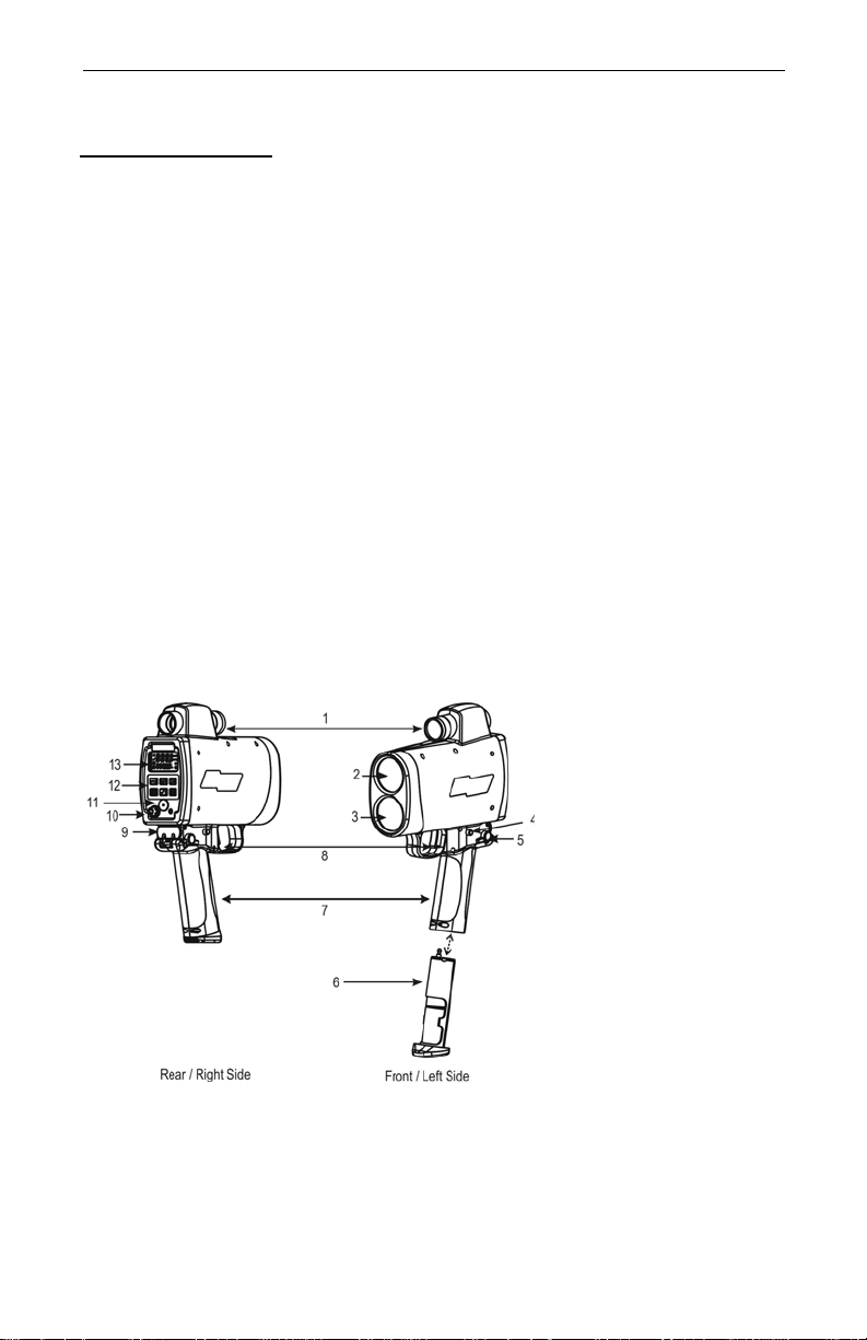
1. Sighting Scope
2. Transmit Lens
3. Receive Lens
4. Battery Release
5. Shoulder Stock
Release
6. Battery Tube
7. Handle / Battery
Compartment
8. TRIGGER
9. Shoulder Stock
Attachment
Point
10. Test Port
11. Speaker
12. Keypad
13. LCD Screen
Figure #1
Page 4
About the TruSpeed
Laser Technology's LTI 20/20 TruSpeed is part of the Laser Technology family of
handheld laser speed and ranging devices. Compared to our other
laser speed measurement products, the TruSpeed includes:
• Simplified menus and options.
• Built-in Weather Mode that is an alternate speed measure ment mode. It
is a simplified gating option. This factory-defined gate ensures that
targets are beyond the range where rain and snow can af fect the lase r's
ability to capture a speed reading.
• Continuous Mode that is an alternate speed measurement mode. It
displays one speed reading after another until you release the TRIGGER.
• Liquid Crystal Display (LCD) screen for instant access to measurements
and options.
• Sighting scope with in-scope aiming reticle and in-scope
speed measurement display.
• Seven-button keypad that provides quick and easy access to the
instrument functions.
• Sounds and visual indicators that ensure confidence of positive target
acquisition.
• Test port for verifying reference timing.
Figure 1 shows the TruSpeed's front and rear panels.
Page 7
Section #1 - Getting Started
Page 5
Sensors
The TruSpeed has two lenses on the front panel. The top lens transmits the
infrared laser signals. The bottom lens receives signals back from the target and
feeds signal information to the internal circuitry.
The internal circuitry consists of a laser range sensor and timing, analysis,
computation, and display circuits. The TruSpeed determines distance through its
laser range sensor, by measuring the time of flight of short pulses of infr ared light.
The TruSpeed has a broad spectrum of sensitivity, and can work with both
reflective and non-reflective targets. The maximum measurement distance varies
with target and environmental conditions. The absolute maximum is about 2,000
feet.
LCD Screen
The LCD Screen displays menu items, option indicators, error codes, and speed
measurement results.
Test Port
Your TruSpeed includes a T est Port located on the rear panel. The T est Port allows
you to connect the instrument to a remote computer for laboratory testing
purposes only.
Sighting Scope
Mounted on top of the TruSpeed is a single-power sighting scope. The scope
features:
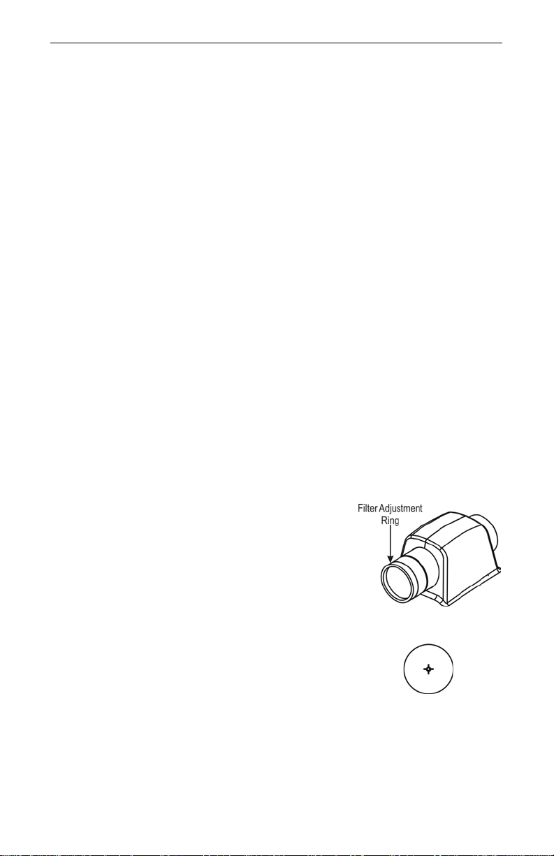
• The polarizing light filter is adjustable to
optimize viewing contrast. Figure #2 shows
the polarizing light filter's adjustment ring.
• In-scope speed measurement display.
• The in-scope aiming reticle helps you aim
accurately to the target. Figure #3 shows
reticle. This reticle represents the size of the
laser beam.
You can vary the intensity of the aiming
L
reticle to account for different lighting
conditions. For more information, see page 13.
Figure #2
Figure #3
Page 8

Laser Technology, Inc. LTI 20/20 TruSpeed User’s Manual
Page 6
Buttons on the Keypad
The T ruSpeed has a 7-but ton keypad located on the r ear panel of the instrument.
The buttons provide easy access to the instrument functions. The table below
lists the buttons and the functions of each.
Button Name Function
Speed
Mode
Activates the instrument’s speed
measurement mode.
Weather
Mode
Continuous
Mode
Backlight Toggles the display backlight
Test
Mode
Brightness
Control
Power ON/
OFF
Activates the instrument’s alternate speed
measurement mode: simplified gating
option. Targets must be at a distance
greater than 200 feet.
Activates the instrument’s alternate speed
measurement mode: displays one speed
reading after another until you release the
trigger.
ON/OFF
Activates the instrument’s Test Mode, which
allows you to verify the TruSpeed’s
mechanics.
Varies the intensity of the in-scope aiming
reticle.
Press and release to power ON the
instrument.
Press-and-Hold for approximately 3 seconds
to power OFF the instrument.
Page 9
Section #1 - Getting Started
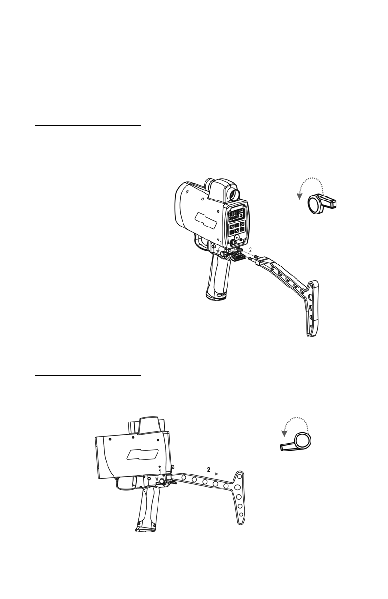
Figure #4
(Enlarged to
show step #1)
Figure #5
(Enlarged to
show step #1)
Page 7
Optional Shoulder Stock
The Shoulder Stock is available for purchase as an accessory item. The Shoulder
Stock helps stabilize the TruSpeed while capturing speed measurements and is
designed for either left-handed or right-handed use.
Attaching the Shoulder Stock
1. Flip the Shoulder Stock Release toward the front of the TruSpeed.
2. Align the pronged-end of the Shoulder Stock with the Shoulder Stock
Attachment Point as shown in Figure #4.
3. Slide the Shoulder Stock straight into the two holes.
4. Flip the Shoulder Stock
Release toward the rear
of the TruSpeed to
secure the Shoulder
Stock.
Removing the Shoulder Stock
1. Turn the Shoulder Stock Release toward the front of the TruSpeed.
Continue to hold the Shoulder Stock Release in this position.
2. Pull the Shoulder Stock straight toward you.
Page 10
Laser Technology, Inc. LTI 20/20 TruSpeed User’s Manual
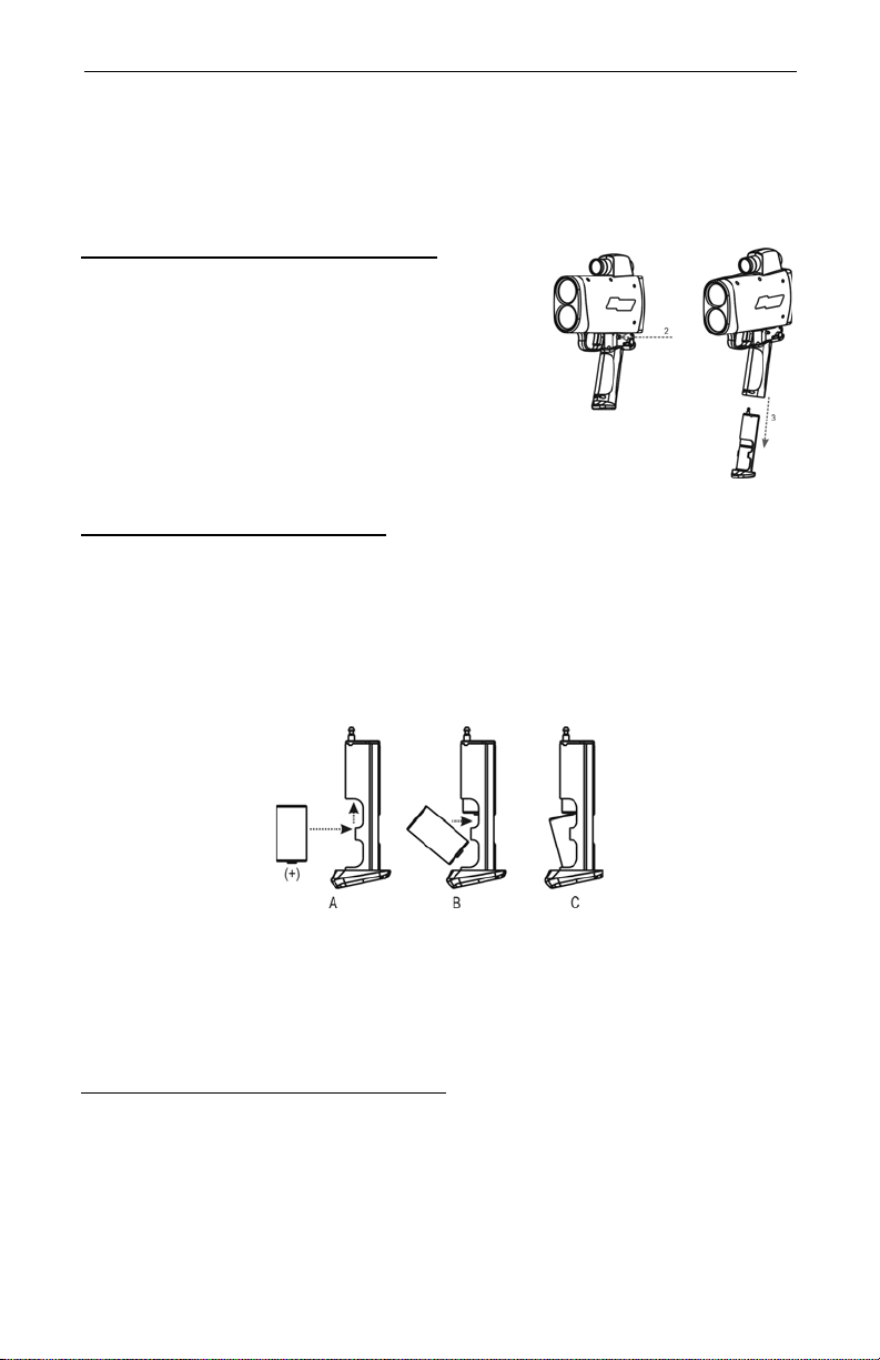
Figure #6
Figure #7
Page 8
Installing / Removing the Batteries
Two C cell batteries are required to power the TruSpeed. The batteries are
located in the Battery Tube inside the Handle.
Removing the Battery Tube from the Handle
1. Hold the T ruSpeed with one hand and
hold the bottom of the Handle with
your other hand.
2. Press the Battery Release, the black
button on either side, just behind the
TRIGGER.
3. Slide the Battery Tube out of the
Battery Compartment.
Inserting the Batteries in Battery Tube
1. With the positive end pointing toward the bottom of the Battery Tube,
align the battery with the opening of the Battery Tube as shown in
Figure #7A and B.
2. Insert the battery into the Battery Tube and slide the battery to the top
of the tube.
3. Position the second battery as described in step #1 and insert the
battery into the tube as shown in Figure #7C.
To remove the batteries from the Battery Tube, just reverse the above
L
instructions.
Re-inserting the Battery Tube into the Handle
The Battery Compartment is designed to the Battery Tube only fits one way.
1. Align the notched edges of the Battery Tube with those of the Battery
Compartment.
2. Slide the tube into the compartment until it locks into place.
Page 11
Section #1 - Getting Started
Page 9
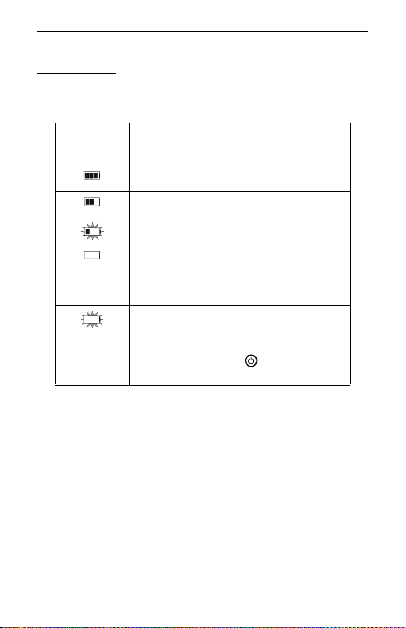
Battery Voltage Level
The TruSpeed continuously monitors its power source. LTI has defined an
acceptable battery voltage range to ensure that the instrument h as sufficient
battery voltage to guarantee correct operation.
Appearance
of the
Battery Icon Explanation
3 segments are lit and the display is steady. The
estimated battery life is between 67% and 100%.
2 segments are lit and the display is steady. The
estimated battery life is between 34% and 66%.
1 segment is lit and the display is flashing. The
estimated battery life is between 33% and 11%.
Only the outline is lit, no segments are lit and the
display is steady. The estimated battery life
approximately 10%, and the instrument is still
operating normally.You should replace the batteries
as soon as possible.
Only the outline is lit, no segments are lit and the
display is flashing. “bAtt” appears in the upper
display and “CHAng” appears in the lower display.
All system operation will be locked out and the only
button that will work is the Button, which you
can use to power oFF the TruSpeed.
Page 12

Laser Technology, Inc. LTI 20/20 TruSpeed User’s Manual
Page 10
Powering ON the TruSpeed
1. Press the TRIGGER or the
button. Briefly, the instrument’s
microcontroller will perform the Self
Test.
•
If all tests prove positive,
and “SELF” appears in the lower display as Figure #8 shows. Then the
Speed Mode will be active and the Speed Measurement Screen (page 16)
will be displayed.
If all tests do not prove positive,
•
in the upper display (page 15).
If the instrument fails the Self Test:
L
1. Press the button to power OFF the TruSpeed.
2. Press the button to once again power ON the
TruSpeed and repeat the Self Test.
“PASS” appears briefly in the upper display
the appropriate error code will appear
¶ If the error repeats and you need assistance, contact LTI.
See the inside front cover for LTI contact information.
Figure #8
Powering OFF the TruSpeed
1. Press and hold the button for approximately 3 seconds.
To help save its batteries, the TruSpeed has a factory-defined power
L
OFF interval. The instrument will automatically power OFF if there is no
activity for a period of 15 minutes. Instrument activity includes any
button presses.
Page 13
Understanding the Display Indicators
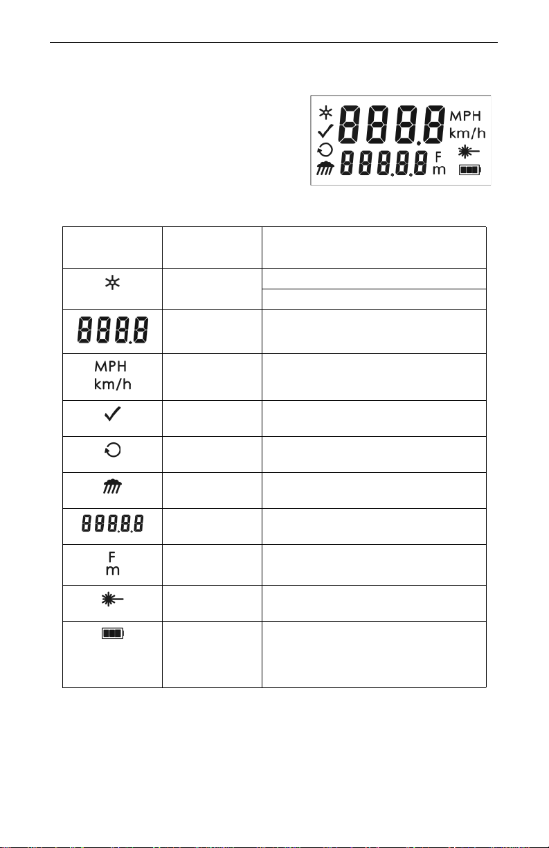
Figure #9
Figure #9 shows the LCD Screen.The table
below lists the display indicators and the
function of each. These are presented in
order of location on the screen, from left to
right starting in the upper left corner.
Display
Indicator Function Explanation
Visible:
Display
Backlight
Upper
Display
The LED backlight is ON.
Not Visible:
Provides access to speed
measurements and messages.
The LED backlight is OFF.
Section #1 - Getting Started
Page 11
Speed
Units
Test
Mode
Continuous
Mode
Weather
Mode
Lower
Display
Range
Units
Laser
Fire
Battery Identifies the approximate current
MPH: Miles per Hour.
km/h: Kilometers per Hour.
The instrument’s Test Mode is active
(page 24).
The instrument’s Continuous Mode is
active (page 22).
The instrument’s Weather Mode is
active (page 21).
Provides access to range
measurements and messages.
F:
Feet.
m:
Meters.
The instrument’s laser is firing.
battery voltage. The indicator shown
here represents 100%-67% battery
life (page 9).
Page 14

Laser Technology, Inc. LTI 20/20 TruSpeed User’s Manual
Page 12
Miscellaneous Display Features
The table below lists the miscellaneous display features.
Display
Feature Explanation
bAtt
CHAng
br xx The in-scope aiming reticle’s intensity
-d1- Delta Distance Test - Distance #1. Appears
-d2- Delta Distance Test - Distance #2. Appears
dEF
CLEAr
E xx Error Code. An error condition has occurred
PASS Successful completion of the instrument
SELF The instrument is performing (or has
SN Serial Number. “SN” appears in the upper
tt The instrument’s test tone is active. Used
You must replace the batteries. Appears in
the upper and lower displays.
setting. Appears in the upper display.
in the upper display.
in the upper display.
The factory default settings have been
restored. Appears in the upper and lower
displays.
during a speed measurement attempt or in
the system hardware. Appears in the upper
display.
Self Test. Appears in the upper display.
performed) the instrument Self Test.
Appears in the lower display.
display. The serial number associated with
the unit appears in the lower display.
during the Scope Alignment Test. Appears
in the upper display.
Refer to
Pages
9
13
29
29
13
15
30
30
30
25
Page 15
Section #1 - Getting Started
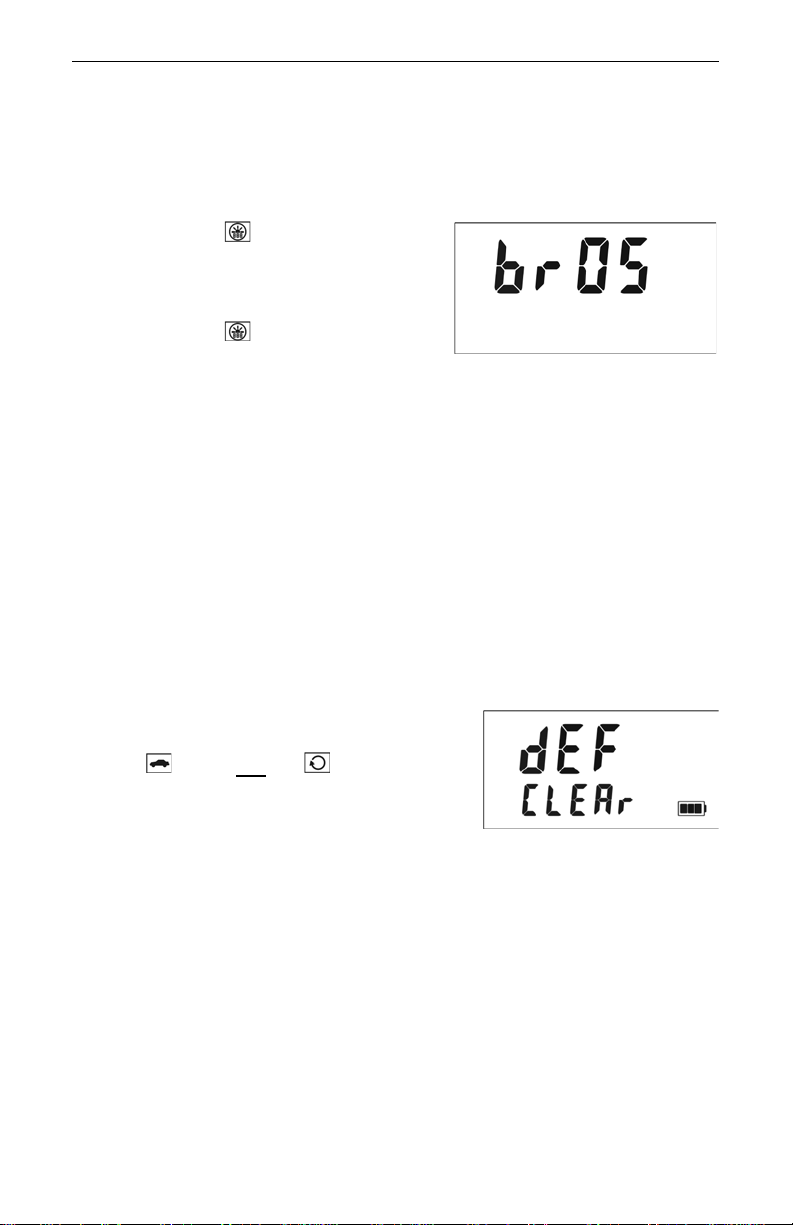
Figure #10
Figure #11
Adjusting the Aiming Reticle's Intensity
The in-scope aiming reticle has eight intensity settings from DIM (01) to
BRIGHT (08).
1. Press the button. The display
should look similar to Figure #10.
The factory default setting is
"br 05" as shown in the figure.
2. Press the button until the
desired setting is achieved. It's
easy to get the desired setting if
you look through the scope while
making the adjustment.
¶ Each time you press the button, the "br xx" value
increases by 1.
¶ If you press the button while "br 08" is displayed,
you will see "br 01" next.
3. Press the TRIGGER to return to the measurement mode that was most
recently active.
• Powering OFF the instrument does not change this setting. The
L
next time the instrument is powered ON, the setting will be the
same.
Page 13
Restoring Factory Default Settings
1. Verify that the TruSpeed is powered ON.
2. Simultaneously, press and hold the
button and
“dEF CLEAr” appears on the screen.
The display should look like Figure #11.
3. Release both buttons. The Speed Mode
will be active and the Speed
Measurement Screen will be displayed.
the button until
Page 16

Laser Technology, Inc. LTI 20/20 TruSpeed User’s Manual
Figure #11
Page 14
Listening to the TruSpeed
The TruSpeed emits a variety of beeps and tones during use. The sounds vary
and depend on what the instrument is doing. The table below lists and explains
each of the sounds.
Sound Explanation
3 Low-Pitched and
1 High-Pitched Beeps
Low-Pitched Growl The instrument is attempting to lock onto a
1 Low-Pitched and
2 High-Pitched Beeps
High-Pitched
Double Beep
High-Pitched
Triple Beep
High-Pitched
Oscillating Ring
Low-Pitched
Single Beep
At Power ON.
target.
The instrument was not able to complete the
intended speed measurement due to an error.
An error code will be displayed to the indicate
the nature of the error (page 15).
The instrument successfully completed the
intended speed measurement.
The laser’s return sensor detected interference
from a light source such as a xenon headlight
or laser jammer device. The speed reading is
valid.
Jam tone. The instrument’s laser return sensor
is being overwhelmed by interference from a
light source such as a headlight or laser jammer
device.
At Power OFF.
Understanding Error Conditions
Although it’s rare, error conditions can occur during a measurement attempt or in
the system hardware. To make sure that you never get an erroneous speed
reading, the T ruSpeed monitors both the system hardware a nd the measurement.
When the instrument detects an error condition, it displays an error code instead
of a measurement.
Figure #11 shows an example of an error
code, “E 03” Measurement error - unstable
targeting.
Page 17

Section #1 - Getting Started
Error Codes
The table below lists and explains each of the possible error codes.
Code Explanation
E 01 Measurement Error - the target was out of range or was too
close.
E 02 Measurement Error - insufficient data. The unit does not have
enough data to measure speed.
Possible Cause:
E 03 Measurement Error - unstable targeting. Data is not stable
enough to measure speed.
Possible Causes:
Measurement Error - low level of interference from a light
source such as a xenon headlight.
E 07 Jam Detect - high level of interference from a light source
such as a xenon headlight.
E 52 Temperature too cold. Stop operation.
E 53 Temperature too hot. Stop operation.
E 55 E57
E 56 E58
E 60 Memory failure. Please turn OFF unit and try again. If the
E 62 Receiver Failure. Please turn OFF unit and try again. If the
E 99 General System Failure. Please contact LTI.
Calibration Errors. Please turn OFF unit and try again.
If the same error is continuously repeated, please contact
**
LTI.
same error is continuously repeated, please contact LTI.
same error is continuously repeated, please contact LTI.
early release of the TRIGGER or time-out.
poor aiming or panning off the target.
**
Page 15
**
**
**See inside front cover for LTI contact information.
RFI Considerations
The T ruSpeed does not display a specific error message indicating the presence of
radio frequency interference (RFI). The instrument's electronics have been
designed for optimum RFI immunity. If RFI is present, the instrument displays an
error code. The exact code depends on the level and nature of the RFI.
Page 18
Laser Technology, Inc. LTI 20/20 TruSpeed User’s Manual
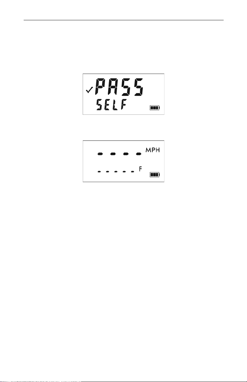
Figure #12
Figure #13
Page 16
Section #2 - Speed Measurements
When you power ON the TruSpeed the instrument will perform the Self Test.
Figure #12 shows successful completion of the Self Test. See page 30 for more
information about the Self Test.
The next screen is automatically displayed and should look similar to Figure #13.
• The dashes that appear in the upper display indicate where the
speed measurement will appear.
• “MPH” means the speed will be measured in miles per hour.
• The dashes that appear in the lower display indicates where the distance
to the target vehicle will appear.
• "F" means the distance will be measured in feet.
• The Battery Icon indicates the approximate battery voltage
level (page 9).
Page 19
Section #2 - Speed Measurements
Figure #14
Taking a Sample Measurement
1. Ensure that the TruSpeed is powered ON and that the Speed Mode is
active.
2. Use the sighting scope and aiming reticle to aim the instrument to a
convenient target - an interior wall will do.
3. To fire the laser:
¶ Press and hold the TRIGGER. The laser will fire after a short delay
(about one-half of a second).
-or-
¶ Press the TRIGGER twice.
The 1st press turns on the in-scope aiming reticle.
The 2nd press takes the measurement.
4. Continue to press the TRIGGER and keep the instrument sighted on the
target:
¶ A low-pitched growl means that the instrument is attempting to lock
onto the target.
¶ 1 Low-Pitched and 2 High-Pitched Beeps mean that a measu rement
error occurred. An error code will be displayed (page 15).
¶ 2 high-pitched beeps mean that a speed was captured. The
measured speed will be displayed on the LCD screen and will be
projected in the scope, just below the aiming reticle.
Page 17
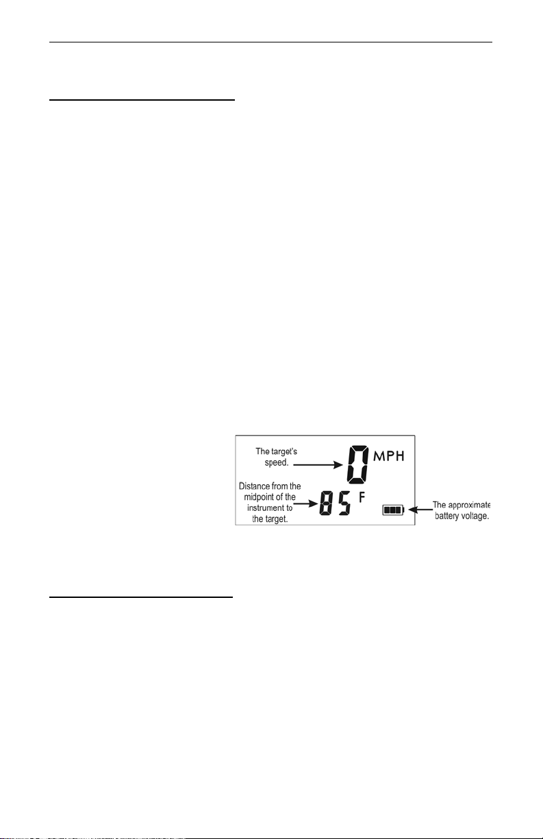
After you release the
TRIGGER, the instrument will
display the most recent speed
reading and the distance at
which it was captured. The
display screen will look similar
to Figure #14. If you did not
capture a speed, an error code
will be displayed (page 15).
Choosing a Roadside Location
When choosing a spot on the side of the road for measuring moving vehicles, you
will need to consider:
• Is the location safe?
• Do you have a clear lin e of sight?
• What is the approximate angle between the instrument's position and
the target vehicle's direction of travel?
• What is the approximate distance to the target vehicles?
• How is the weather? Will you need to use the Weather Mode?
Page 20

Laser Technology, Inc. LTI 20/20 TruSpeed User’s Manual
Page 18
Line of Sight
Ideally, you should have a clear line of sight to the target vehicle.
If there is a momentary break in the beam,
•
accumulate data and may be able to capture the target vehicle's speed.
The instrument will display an error code if it cannot capture the target
vehicle's speed.
If there is an extended break in the beam,
•
error code.
the instrument will
the instrument will display an
The Cosine Effect
If the target vehicle is moving directly toward or away from you, the speed
measured by the TruSpeed is identical to the vehicle's true speed. However, the
instrument is usually set up on the side of the road for safety. This results in an
angle between the instrument's position and the target vehicle's direction of
travel. When the angle is significant, the measured speed is less than the target's
true speed. The phenomenon is known as the cosine effect. Cosine is the
trigonometric function that relates to this phenomenon.
The difference between the measured speed and the true speed depends upon
the angle between the instrument's ideal position- the position where targets
would be moving in direct line with the instrument- and its actual position.
• The larger the angle, the lower the measured speed.
L
• The effect always works to the motorist’s advantage.
• Loosely speaking, the cosine effect is not significant as long as the
angle remains small. The table below shows this effect.
Measured Speed by Angle: The Cosine Effect:
Angle
(degrees)
0 30.00 40.00 50.00 60.00 70.00
1 29.99 39.99 49.99 59.99 69.99
3 29.96 39.94 49.93 59.92 69.90
5 29.89 39.85 49.81 59.77 69.73
10 29.54 39.39 49.24 59.09 68.94
15 28.98 38.64 48.30 57.94 67.61
20 28.19 37.59 46.99 56.38 65.78
45 21.21 28.28 35.36 42.43 49.50
90 00.00 00.00 00.00 00.00 00.00
30 MPH 40 MPH 50 MPH 60 MPH 70 MPH
True Speed
Measured Speed (MPH)
Page 21

Section #2 - Speed Measurements
Page 19
The cosine effect decreases as the range to the target vehicle increases.
• At the maximum range of the instrument, the vehicle is so far away that
the angle between it and the instrument is very small indeed. The
instrument's perception of the target's speed is identical to its true
speed.
• As the vehicle approaches, the angle increases until it becomes large
enough to affect the measurement.
To minimize the cosine effect, keep the angle small. Set up the
L
instrument as close to the road as possible without creating safety
risks, and target down the road at ranges sufficient to keep the angular
difference small.
The table below shows acceptable parameters for minimizing the cosine effect.
The chart indicates the percentage of true speed measured, given the distance
from the roadway and the distance from the target vehicle. To find a target's
measured speed, multiply the true speed by the number in the chart.
Distance
off the
roadway
(feet)
10
25 .9682
50 .8660 .9798
100 .0000 .9165 .9798
200 .0000 .6000 .9165 .9798
The diagonal created by the boldface numbers indicates the boundary between
acceptable and unacceptable parameters.
•Numbers
•Numbers
Remember that the cosine effect is always in the motorist's favor.
As a general rule, do not exceed 10 f eet of f the r oad f or ev ery 100 f eet
L
shooting down range to the targets. If target vehicles will be 500 feet
down the road, set up no more than 50 feet off the road.
100 ft 250 ft 500 ft 1000 ft 2000 ft
fraction of the True Speed that will be measured
.9950
above
the diagonal are acceptable margins of error.
below
the diagonal are unacceptable margins of error.
Range to Target Vehicle
.9992 .9998 .9999 1.0000
.9950
.9987 .9997 .9999
.9950
.9987 .9997
.9950
.9987
.9950
Page 22

Laser Technology, Inc. LTI 20/20 TruSpeed User’s Manual
Figure #15
Page 20
Measuring a Moving Vehicle
1. Ensure that the TruSpeed is powered ON and that the Speed Mode is
active.
2. Use the aiming reticle to aim the instrument at the target vehicle's
license plate area and press the TRIGGER.
3. Continue to press the TRIGGER and keep the instrument sighted on the
target
¶ A low-pitched growl means that the instrument is attempting to lock
onto the target.
¶ A low-pitched beep means that a measurement error occurred. An
error code will be displayed.
¶ A high-pitched double beep means that a speed was captured. The
measured speed will be projected in the scope just below the
aiming reticle.
While the instrument is attempting to lock onto the target, as long as the
TRIGGER is kept pressed, it will retry the speed measurement.
• In this mode, the instrument will attempt to lock onto the target for up
to 5 seconds. Information is accumulated until it gets a good
measurement or generates an error code.
• Consequently, it is very important that the aiming point on the target
remain constant for the entire measurement time. If you move the
instrument off the aiming point, it will gene r ate an err or code inst ead of
capturing a speed reading.
After you release the TRIGGER the
instrument will display the most recent
speed reading and the distance at which
it was captured or an error code. When
the most recent speed reading is
displayed, the display screen will look
similar to Figure #15.
• The speed displays as a
from you when it was measured.
• The speed displays as a
you when it was measured.
negative number
positive number
if the target was going away
if the target was approaching
Page 23
Section #2 - Speed Measurements
Figure #16
Page 21
Using the Weather Mode
Moisture is reflective. Weather such as rain, snow, or fog can make it difficult for
the laser to receive signals back from the target. This is especially true when you
are trying to capture speeds at close range. The TruSpeed includes a built-in
Weather Mode that is an alternate speed measurement mode. When the Weather
Mode is active, the factory-defined gate setting increases the instrument's
minimum range from 50 ft to 200 ft. Increasing the minimum range ensures that
the laser only acquires targets beyond the range where we ather affects the laser's
ability to capture a speed reading.
When the Weather Mode is active:
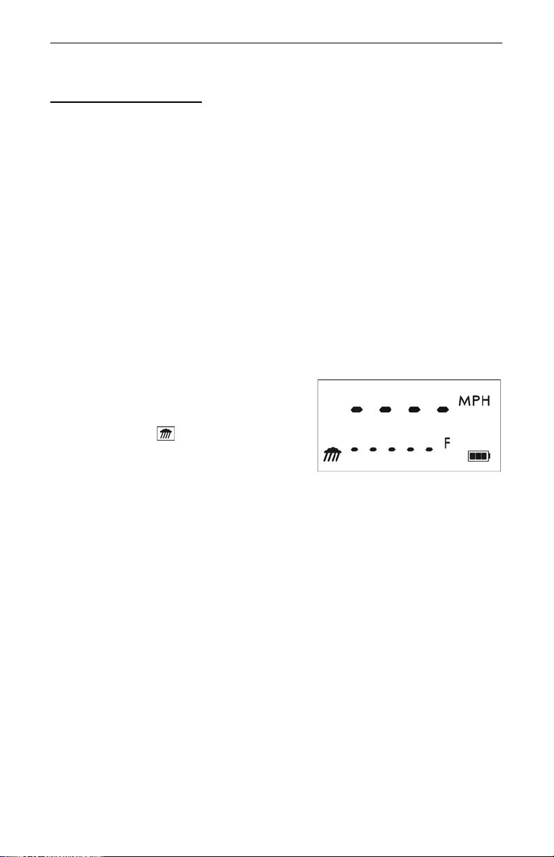
• The Weather Mode indicator appears in the lower left corner of the LCD
Screen.
• Targets must be a distance greater than 200 feet.
• The instrument's maximum range is not changed.
• Other than the above items, the TruSpeed operates the same as when
the Speed Mode is active and the Weather Mode is not active.
To activate the Weather Mode.
1. Ensure that the TruSpeed is
powered ON.
2. Press the button. The display
should look similar to Figure #16.
3. Aim the instrument at the target
vehicle's license plate area and
press the TRIGGER.
4. Continue to press the TRIGGER, and keep the instrument sighted on the
target:
¶ A low-pitched growl means that the instrument is attempting to lock
onto the target.
¶ A low-pitched beep means that a measurement error occurred. An
error code will be displayed.
¶ A high-pitched double beep means that a speed was captured. The
measured speed will be projected in the scope just below the aiming
reticle.
While the instrument is attempting to lock onto the target, as long as the
TRIGGER is kept pressed, it will retry the speed measurement.
• In this mode, the instrument will try up to 5 seconds. Information is
accumulated until it gets a good measurement or generates an error
code.
• Consequently, it is very important that the aiming point on the target
remain constant for the entire measurement time. If you move the
instrument off the aiming point, it will generate an error code instead of
capturing a speed reading.
Page 24
Laser Technology, Inc. LTI 20/20 TruSpeed User’s Manual
Figure #17
Figure #18
Page 22
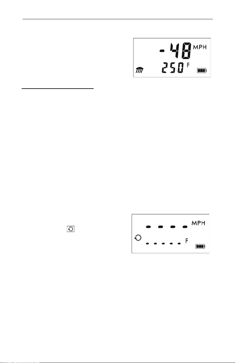
After you release the TRIGGER the
instrument will display the most recent
speed reading and the distance at which it
was captured or an error code. When the
most recent speed reading is displayed, the
display screen will look similar to Figure #17.
Using the Continuous Mode
Continuous Mode is an alternate speed measurement mode. If you wish to take
several successive readings on a targe t, you can put the instrume nt in Continuous
Mode. In this mode, the instrument takes and displays on e reading after another,
and continues to take and display readings as long as you hold down the
TRIGGER. Release the trigger, and the instrument finishes its latest reading and
stops. If an error code is shown when you release the trigger, the instrument will
display either the most recent speed reading, or, if the error code has persisted
for several tries, the error code will remain.
When the Continuous Mode is active:
• The Continuous Mode indicator appears in the middle left side of the
LCD Screen.
• For the best results, do not try to use Continuous Mode to target one
vehicle after another.
• When you wish to change targets, release the trigger, aim to the new
target, and retrigger.
To activate the Continuous Mode:
1. Ensure that the TruSpeed is
powered ON.
2. Press the button. The display
should look similar to Figure #18.
3. Aim the instrument at the target
vehicle's license plate area and
press the TRIGGER.
4. Continue to press the TRIGGER
and keep the instrument sighted
on the target:
¶ A low-pitched growl means that the instrument is attempting to lock
onto the target.
¶ A low-pitched beep means that a measurement error occurred. An
error code will be displayed.
¶ A high-pitched double beep means that a speed was captured. The
measured speed will be projected in the scope just below the
aiming reticle.
Page 25
Section #2 - Speed Measurements
Figure #19
Page 23
While the instrument is attempting to lock onto the target, as long as the
TRIGGER is kept pressed, it will retry the speed measurement.
• In this mode, the instrument will try up to 5 seconds. Information is
accumulated until it gets a good measurement or generates an error
code.
• Consequently, it is very important that the aiming point on the target
remain constant for the entire measurement time. If you move the
instrument off the aiming point, it will generate an error code instead of
capturing a speed reading.
• The instrument will take and display one r eading after another as lon g as
you hold down the TRIGGER.
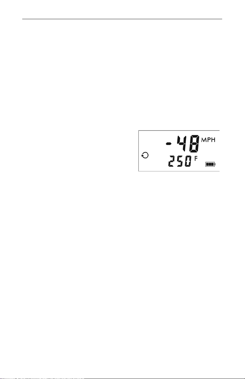
After you release the TRIGGER the
instrument will display the most recent
speed reading and the distance at which
it was captured or an error code. When
the most recent speed reading is
displayed, the display screen will look
similar to Figure #19.
Laser Jammer Detection
The L TI 20/20 TruSpeed contains advanced circuitry and algorithms that allow the
instrument to determine if a laser jammer is bein g used. Th e JAM to ne (page 14)
indicates that the instrument is being flooded by a light source. There are two
possible situations:
• You are targeting a strong light source such as xenon headlights.
-or-
• A targeted vehicle is employing a laser jammer.
Regardless of the level of interference, you will never get an erroneous speed
reading.
• If the laser jammer uses “smart” technology, you will hear the jam tone
and the measured speed will flash.
• If the laser jammer does not use “smart” technology or if the
interference is from a light source other than a laser jammer:
¶ At a low level of interference, you will hear the jam tone and a
speed may be captured or an E03 error code may be displayed.
¶ At a high level of interference, you will hear the jam tone and an
E07 error code will be displayed.
Page 26
Laser Technology, Inc. LTI 20/20 TruSpeed User’s Manual
Figure #20
Page 24
Section #3 - Test Mode and Instrument Te sts
The Test Mode includes 6 options and allows you to verify the TruSpeed's
mechanics. These options include:
• Display Integrity Test
• Scope Alignment Test
• Delta Distance Test
¶ Fixed Distance Test
•Self Test
• Model and Firmware Version Number Display
• Serial Number Display
Display Integrity Test
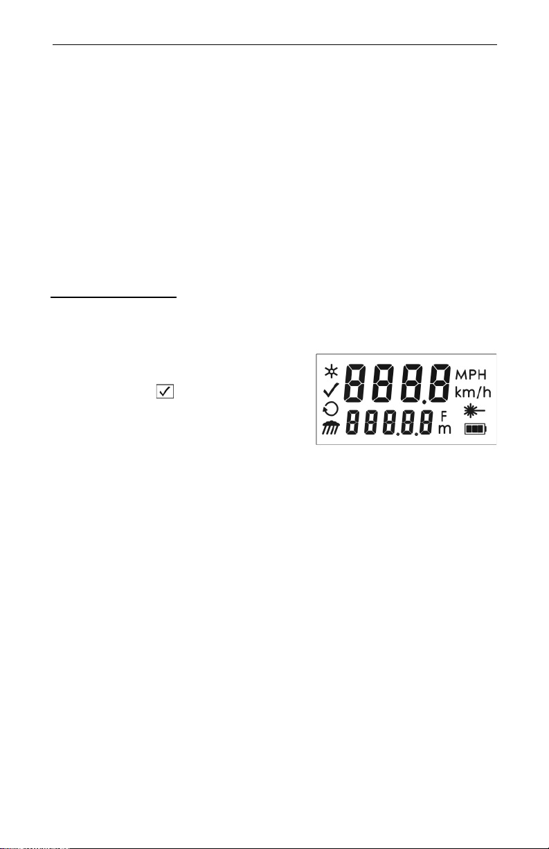
The Display Integrity Test allows you to verify that all display segments are
operating. LTI suggests that you do this test periodically.
1. Ensure that the T ruSpeed is powered
ON.
2. Press the button. The display
should look like Figure #20.
3. Compare the instrument's display to
Figure #20. If any segment fails to
display, contact Laser Technology,
Inc. to arrange for repair. See the
inside front cover for LTI contact
information.
The display integrity is also tested each time the unit is powered ON.
L
However, the results are only briefly displayed before the results of the
Self Test are displayed.
Page 27

Section #3 - Test Mode and Instrument Tests
Figure #21
Page 25
Scope Alignment Test
Scope alignment is set at the factory when the instrument is shipped. A heavy
blow is the only reason that the scope might ever go out of alignment.
LTI suggests that you do this test periodically.
The Scope Alignment Test uses sound to indicate when the scope is on-target.
1. Select a target. Choose a prominent target with well-defined horizontal
and vertical edges. A telephone pole is an excellent choice.
¶ Recommended distance to target: 650 feet.
¶ The target's reflective qualities and distance should be such that you
can clearly hear a change in pitch of the test tone as you pan the
instrument over the edges of the target.
¶ Make sure there is nothing behind the target that the instrument
might detect, so you know without a doubt that any change in pitch
is due strictly to the target.
2. Ensure that the TruSpeed is powered ON.
3. Press the button two times to activate
the Test Tone display screen. It should
look like Figure #21.
4. Scan the target. Press and hold the
TRIGGER while panning the instrument
across the target. The tone changes pitch
when the instrument acquires the target.
The highest pitch - the on-target tone should occur when the in-scope aiming
reticle is centered on the target. Scan the
target both horizontally and vertically.
¶ If the frequency drops off at equal distances from the center of the
aiming reticle, the instrument needs no adjustment.
¶ Otherwise, contact Laser Technology, Inc. for assistance with
re-aligning the scope. See the inside front cover for LTI contact
information.
When checking vertical alignment to a close target, be aware of the
L
offset between the center of the scope and the center of the transmit
lens, which is 2 inches.
Page 28

Laser Technology, Inc. LTI 20/20 TruSpeed User’s Manual
Page 26
Instrument Confidence Checks
There are several ways to verif y the measurement accuracy of a Lidar instrument.
You can verify it directly by measuring the speed of an object traveling at a
known speed, but this is seldom practical. The nature of Lidar is such that it
cannot be tricked by a vibrating object, such as a tuning fork, into displaying a
velocity. For these reasons, LTI has designed the Fixed Distance Test and the
Delta Distance Test. LTI suggests that you do one of these tests each time the
instrument is taken on duty.
Theses tests verify the accuracy of the two key elements of Lidar speed
measurement:
• Precise time measurements
• Ability to make mathematical calculations
When setting up an area for these tests, LTI recommends:
• Permanently installing the test area in a convenient location. The test
area must establish a permanent, known distance between a shooting
mark and a target (Fixed Distance Test) or between a shooting mark and
two targets (Delta Distance Test).
• Using a metal tape to measure the distance; this will ensure that the
measurement is accurate.
Other considerations:
• The shooting mark is where you stand to do the test, and can be an "X"
painted on the pavement.
• A target can be any flat, permanent structure-a sign or wall, for
example-painted with a bull's eye or other aiming point.
• The shooting mark and the target must form a straight line.
• The distance specified is horizontal distance. Horizontal distance is
measured along a straight, level path from the shooting mark to the
center of the aiming point.
• The manner in which you stand and hold the in strume nt both a f fect the
test measurements. For exact readings, carefully hold the instrument so
it is directly over the middle of the X.
Page 29
Section #3 - Test Mode and Instrument Tests
Figure #22
Fixed Distance Test
The Fixed Distance Test is not one of the options included in the Test
L
Mode. In order to perform the Fixed Distance Test, the Speed Mode
must be active.
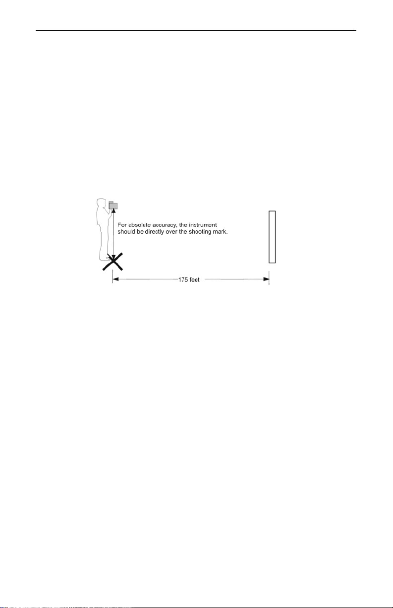
The Fixed Distance Test requires one target:
• LTI recommends that the target should be 175 feet from the shooting
mark. See Figure #22. If there is not enough space available, that
specific distance is not c rucial. H owever, the distance between the target
and the shooting mark must be a multiple of 1 foot, not a fraction of a
foot.
Page 27
1. Stand on the shooting mark.
2. Ensure the TruSpeed is powered ON and that the Speed Mode is active.
3. Aim at the target.
4. Press the TRIGGER.
5. Check the display. The speed reading should be zero. A reading of zero
verifies the timing accuracy of the instrument and is identical in nature to
an accurate velocity reading of a vehicle moving at any speed.
¶ The displayed distance should read from 174.5 to 175.5 feet if yo ur
fixed distance was 175 feet.
If you need assistance, contact Laser Technology, Inc. See the inside
L
front cover for LTI contact information.
Page 30
Laser Technology, Inc. LTI 20/20 TruSpeed User’s Manual
Figure #23
Page 28
Delta Distance Test
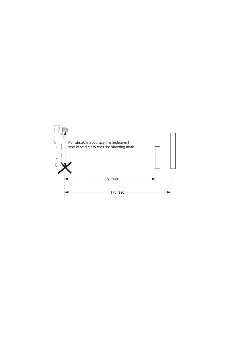
The Delta Distance Test requires two targets. LTI recommends that the first
target should be 150 feet from the shooting mark, and the second should be
175 feet from the mark. See Figure #23. If there is not enough space available,
that specific distance is not crucial. However , the distance between the target and
the shooting mark must be a multiple of 1 foot, not a fraction of a foot.
Refer to Figure #23 as a guide for positioning the targets and the shooting mark.
1. Install the farther target.
2. Measure 175 feet to the shooting mark and mark the shooting spot.
3. Measure from the shooting mark 150 feet to the second target.
4. Mark that spot and install that target.
Page 31
Section #3 - Test Mode and Instrument Tests
Page 29
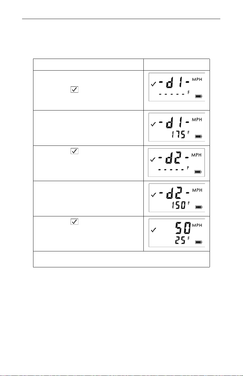
T o conduct the test, r efer to the table below . Note that, for display purposes, each
measurement is rounded to whole feet.
Action Results
1. Stand on the shooting mark.
2. Power ON the TruSpeed and
press the button 3 times until the
message -d1- appears in the upper
display.
3. Aim to the far target and press the
TRIGGER.
4. Check the display. If necessary, you
may repeat step #3.
5. Press the button. The message
-d2- appears in the upper display.
6. Aim to the near target and press the
TRIGGER.
7. Check the display.
If necessary, you may repeat step #6.
8. Press the button. The screen
displays the simulated speed (50 MPH)
±1 MPH and the difference between
the two distances (25 F) ±6 inches.
If the targets are shot in reverse order, the display is the same,
but the simulated speed appears as a negative number
If the difference is 25 feet, the displayed simulated speed should be 49, 50, or
51 MPH, and the distance should be 24.5, 25.0, or 25.5 feet.
If you need assistance, contact Laser Technology, Inc. See the inside
L
front cover for LTI contact information.
Page 32
Laser Technology, Inc. LTI 20/20 TruSpeed User’s Manual
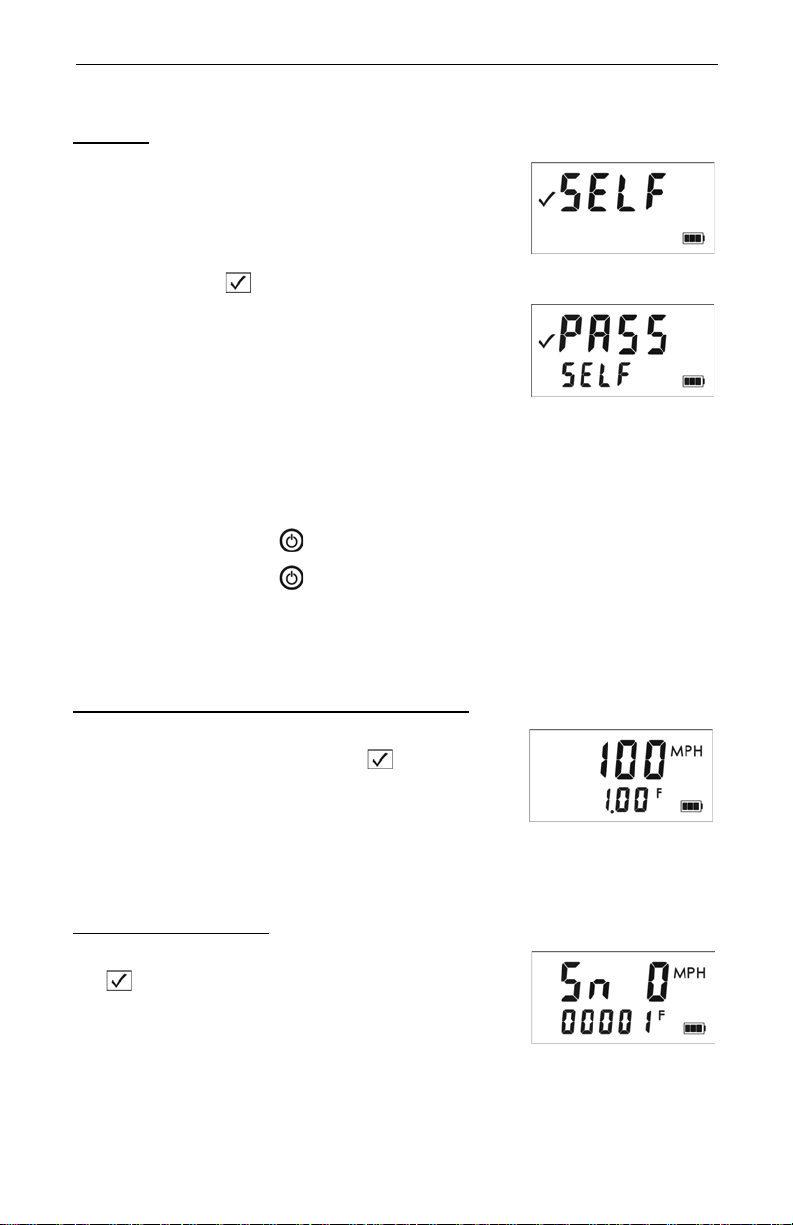
Figure #24
Figure #25
Figure #26
Figure #27
Page 30
Self Test
Just like when the instrument is powered ON, during
the Self Test the microcontroller interrogates the
system electronics.
To display the Self Test:
1. Press the button 4 times. Figure #24
shows the initial screen display.
2. Press the TRIGGER to complete the Self
Test. Figure #25 shows an example of all
tests proving positive.
¶ If all tests do not prove positive, the
appropriate error code will appear in
the upper display (see page 15).
If the instrument fails the Self Test:
L
1. Press the Button to power OFF the TruSpeed.
2. Press the Button to once again power ON the
TruSpeed and repeat the Self Test.
3. Contact LTI if the error repeats and you need assistance. See
the inside front cover for LTI contact information.
Model and Firmware Version Number Display
To display the model number and firmware version
number of your TruSpeed, press the button
5 times. The model number appears in the upper
display and the firmware version number appears in
the Lower Display. The display should look similar to
Figure #26. In this example, the model number is
“100” and the firmware version number is “1.00”.
Serial Number Display
To display the serial number of your TruSpeed, press
the button 6 times. The serial number has 6
digits and appears in the upper and lower display.
The display should look similar to Figure #27. In this
example, the serial number is “000001”.
Page 33

Section #4 - Maintenance
Page 31
Section #4 - Maintenance
Operating Temperature
The instrument is rated for a temperature range of -22° F to +140° F.
Do not operate the instrument in temperatures outside that range.
Moisture and Dust Protection
The TruSpeed is sealed to provide protection from normally encountered field
conditions. It is protected from dust and light moisture.
Shock Protection
The TruSpeed is a precision instrument and should be handled with care. It will
withstand a reasonable drop shock. If you drop the instrument, check the scope
alignment (page 25) before using the instrument for speed measurement.
Cleaning and Storage
Clean the instrument after each use. Check for the following:
Excess moisture.
•
room temperature.
Exterior dirt.
•
remove dirt and fingerprints from the scope exterior.
Dirty lenses.
•
from the front panel lenses. To clean a lens, moisten it with lens cleaning
solution and wipe it with a clean cloth or lens tissue.
Batteries.
•
batteries before storing it.
Caring for the Scope
Do not attempt to lubricate the scope. It is sealed from within using o-rings and
special compounds. All seals are permanent and require no maintenance.
Use a lens brush to remove surface dust and loose particles. To clean a lens,
moisten it with lens cleaning solution and wipe it with a clean cloth or lens tissue.
Checking the Screen Display
The instrument provides a method of verifying the display integrity. For more
information, see page 24.
Restoring Factory Default Settings
See page 13.
T o wel off ex cess moistur e and air dry the in strument at
Wipe exterior surfaces clean. Use isopropyl alcohol to
Use a lens brush to remove su rface dust and loose particles
If you won't be using the instrument again soon, remove the
Page 34

Laser Technology, Inc. LTI 20/20 TruSpeed User’s Manual
Page 32
Section #5 - Specifications
Weight: 2.75 lb. (with batteries)
Size: 7.75 x 3 x 11.75 in.
Acquisition Time: 0.33 sec
Speed Accuracy: ±1 mph
Minimum Range:
Speed Mode: 50 feet
Weather Mode: 200 feet
Continuous Mode; 50 feet
Maximum Range: 2,000 feet
Speed Measurement Range: ±200 mph
Range Accuracy: ±6 inches
Range Resolution: 1 foot
Beam Divergence: 2.5 milliradians nominal
Laser Wavelength: 905 nanometers nominal
Temperature Range: -22° F to +140° F
Power: Two alkaline, NiCad, or NiMH rechargeable
C-cell batteries providing up to 25 hours of
cordless operation.
Eye Safety: FDA Class 1 (CFR 21)
Environment: Water resistant
NEMA 4 and IP 55
Construction: Composite Polycarbonate Outer Shell
Aluminum Internal Chassis
Page 35

Section #6 - Troubleshooting Tips
What You Will See Required Action
Unit powers OFF by
itself.
-orNo power at all.
The in-scope aiming
reticle is not visible.
E01 error code.
No range or speed
readings.
Erroneous readings/not
repeatable.
Limited Range. • Do you have a clear line of sigh t?
Difficult to acquire
target while aiming
through windshield.
Difficult to acquire
target while aiming
through rain or snow.
• Verify that the batteries are installed correctly.
• Replace the batteries.
• Keep in mind that the instrument automatically
powers OFF if there is no instrument activity for a
period of 15 minutes.
• Press the TRIGGER to activate the aiming reticle.
• Press the button to increase the intensity of
the aiming reticle.
• Adjust the polari zing filter.
• Can you measure to a wall that is about 50 feet
away?
• Check the scope alignment.
• Restore the factory defaults.
• When measuring a short range to a small target,
aim slightly above the target.
• Do you have a clear line of si ght?
• Check the scope alignment.
• Is it raining or foggy. If yes, is the W eat her Mode
active? If not, turn it ON. Keep in mind that the
minimum range will be 200 feet.
• When measuring a short range to a small target,
aim slightly above the target.
• Rain or fog will reduce the unit’s maximum
range.
• Is the Weather Mode active? If not, turn it ON.
Keep in mind that the mini mum range will be 200
feet.
• Keep in mind that acquiring a target through
glass will reduce the unit’s maximum range.
• Make sure the lens is clean.
• Check the lens for scratches.
• Is the Weather Mode active? If not, turn it ON.
Keep in mind that the mini mum range will be 200
feet.
• If the windshield is bubble-shaped, shoot
through the center of the windshield .
• • Is the Weather Mode active? If not, turn it ON.
If not, turn it ON. Keep in mind that the minimum
range will be 200 feet.
Section #6 - Troubleshooting Tips
Page 33
Page 36

Laser Technology, Inc. LTI 20/20 TruSpeed User’s Manual
Page 34
Section #7 - Glossary
beam divergence: The tendency of a laser beam to expand in
diameter as it moves away from the source,
measured in milliradians (mrad).
Continuous Mode: Alternate speed measurement mode. Allows you
to take several successive readings of a target
vehicle. Re-trigger for each new target. See page 22.
Delta Distance Test: Uses two measurements each to a known
distance to verify the measurement accuracy of
the TruSpeed. See page 28.
Display Integrity Test: Allows you to verify that all segments of the LCD
screen are operating. See page 24.
Fixed Distance Test: Uses one measurement to a known distance to
verify the measurement accuracy of the
TruSpeed. See page 27.
laser:
lidar: A device that is similar in operation to radar, but
microcontroller: The computer processor that controls all of the
Receive Lens: Located on the front panel of the TruSpeed, it is
reticle: A scale located in the sighting scope that helps
Transmit Lens: Located on the front panel of the TruSpeed, it is
Weather Mode: Alternate speed measurement mode. The laser
Light Amplification by Stimulated Emission of
Radiation.
emits pulsed laser light instead of radio waves.
functions of the TruSpeed.
the bottom lens and receives the signals back
from the target and then feeds the signal
information to the microcontroller.
you aim to your target. It is visible when the
TruSpeed is powered ON. You m a y need to press
the TRIGGER to see the reticle. See page 5.
the top lens and transmits the infrared laser
signals.
only acquires targets that are beyond the range
where weather affects the laser’s ability to
capture a speed reading. Targets must be at a
distance greater than 200 feet. See page 21.
Page 37

Index
Page 35
Index
A
accessories 3
acquisition time 32
adjustment ring
filter 5
aiming reticle 5
brightness 13
not visible 33
B
Backlight button 6
bAtt CHAng 12
batteries
inserting 8
Battery
display indicator 9, 11
battery
voltage level
Battery Release 4, 8
Battery Tube 4, 8
beam divergence 32, 34
beeps 14
br xx 12
brightness
of the aiming reticle 13
Brightness Control button 6
buttons 6
9
C
cleaning 31
confidence checks 26
construction 32
Continuous Mode 22, 34
display indicator 11
Continuous Mode button 6
cosine effect 18
minimizing 19
D
-d1- 12, 29
-d2- 12, 29
dEF CLEAr 12, 13
Delta Distance Test 28, 34
Delta Distance Text
results 29
Display Backlight
display indicator 11
display indicators 11
Display Integrity Test 24, 34
drop shock 31
dust protection 31
E
E xx 12
environment 32
error codes 15
error conditions 14
eye safety 3, 32
F
filter 5
filter adjustment ring 5
firmware version number 30
Fixed Distance Test 27, 34
front panel 4
H
Handle / Battery Compartment 4
K
Keypad 4
Page 38

Laser Technology, Inc. LTI 20/20 TruSpeed User’s Manual
Page 36
L
laser 34
Laser Fire
display indicator 11
laser jammer detection 23
laser wavelength 32
LCD Screen 4, 5
LCD screen 11
lenses 5
lidar 34
limited range 33
line of sight 18
Lower Display
LCD display
11
M
maximum range 32
measured speed 18
microcontroller 34
minimum range 32
Weather Mode 21
moisture protection 31
N
negative value
speed display 20
no power 33
P
panels
front and rear 4
PASS 12
polarizing light filter 5
positive value
speed dispaly 20
power 32
power OFF interval 10
Power ON/OFF button 6
powering
OFF
10
ON 10
R
range 32
accuracy and resolution 32
Range Units
display indicator 11
rear panel 4
Receive Lens 4, 5, 34
restore factory defaults
factory defaults
how to restore 13
reticle 5, 34
RFI considerations 15
roadside location
how to choose
17
O
OFF 10
ON 10
operating temperature 3, 31
Page 39

Index
Page 37
S
safety 3
scope
caring for 31
Scope Alignment Test 25
SELF 12
Self Test 30
serial number display 30
shock protection 31
Shoulder Stock 7
Shoulder Stock Attachment Point 4
Shoulder Stock Release 4
Sighting Scope 4
sighting scope 5
size 32
SN 12
sounds 14
Speaker 4
specifications 32
speed accuracy 32
speed measurements
Continuous Mode 22
how to take 17
LCD screeen 16
moving vehicle 20
negative vlaue 20
range 32
Weather Mode 21
Speed Mode 16
Speed Mode button 6
Speed Units
display indicator 11
storage 31
T
temperature range 3, 32
Test Mode 24
display indicator 11
Test Mode button 6
Test Port 4, 5
test tone 25
tones 14
Transmit Lens 4, 5, 34
TRIGGER 4
troubleshooting tips 33
true speed
percentage measured 19
tt 12
U
Unit powers OFF 33
Upper Display
LCD display 11
V
views
of the TruSpeed 4
W
Weather Mode 21, 34
display indicator 11
Weather Mode button 6
weight 32
windshield
aiming through
33
Page 40

Laser Technology, Inc. LTI 20/20 TruSpeed User’s Manual
Page 38
NOTES:
 Loading...