

Page 1
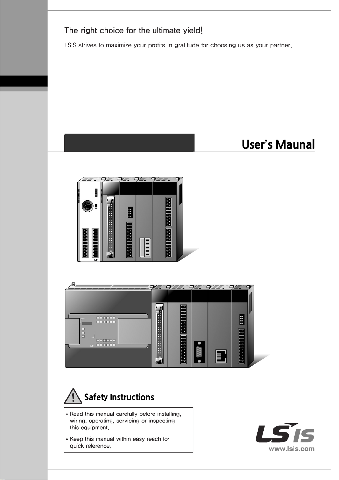
Programmable Lo gic C ontroller
XGB Load Cell Input Module
XBF
XGT Series
-LD02S
Page 2

Safety Instructions
Warning
Caution
Before using the product …
For your safety and effective operation, please read the safety instructions thoroughly before using
the product.
► Safety Instructions should always be observed in order to prevent accident or risk with the safe
and proper use the product.
► Instructions are divided into “Warning” and “Caution”, and the meaning of the terms is as follows.
WARNING indicates a potentially hazardous situation which,
if not avoided, could result in death or serious injury
CAUTION indicates a potentially hazardous situation which,
if not avoided, may result in minor or moderate injury.
It may also be used to alert against unsafe practices
Moreover, even classified events under its caution category may develop into serious accidents
relying on situations. Therefore we strongly advise users to observe all precautions properly just like
warnings.
► The marks displayed on the product and in the user’s manual have the
following meanings.
Be careful! Danger may be expected.
Be careful! Electric shock may occur.
► The user’s manual even after read shall be kept available and accessible to
any user of the product.
Page 3
Safety Instructions
dog timer error, module installation error, etc.) is detected
Warning
Safety Instructions for design process
Please install a protection circuit on the exterior of PLC so that the
whole system may operate safely regardless of failures from
external power or PLC. Any abnormal output or operation from PLC may cause serious
problems to safety in whole system.
- Install protection units on the exterior of PLC like an interlock circuit that deals with
opposite operations such as emergency stop, protection circuit, and forward/reverse
rotation or install an interlock circuit that deals with high/low limit under its position
controls.
- If any system error (watchduring CPU operation in PLC, all output signals are designed to be turned off and
stopped for safety. However, there are cases when output signals remain active due to
device failures in Relay and TR which can’t be detected. Thus, you are recommended
to install an addition circuit to monitor the output status for those critical outputs which
may cause significant problems.
Never overload more than rated current of output module nor
allow to have a short circuit. Over current for a long period time may cause a fire .
Never let the external power of the output circuit to be on earlier than PLC power,
which may cause ac ci dents from abnormal output or operation.
Please install interlock circuits in the sequence program for safe operations in the
system when exchange data with PLC or modify operation modes using a computer
or other external equipments Read specific instructions thoroughly when conducting
control operations with PLC.
Page 4
Safety Instructions
Caution
a module or an
If the product is installed loosely or incorrectly, abnormal
Caution
Safety Instructions for design process
I/O signal or communication line shall be wired at least 100mm
away from a high-voltage cable or power line. Fail to follow this instruction may cause
malfunctions from noise
Safety Instructions on installation process
Use PLC only in t he environment specified in PLC manua l or general standard of
data sheet. If not, electric shock, fire, abnormal operation of the product may be caused.
Before install or remove the module, be sure PLC power is off. If not, electric shock or
damage on the product may be caused.
Be sure that every module is securely attached after adding
extension connector.
operation, error or dropping may be caused. In addition, contact failures under poor cable
installation will be causing malfunctions as well.
Be sure that screws get tighten securely under vibrating environments. Fail to do so
will put the product under direct vibrations which will cause electric shock, fire and
abnormal operation.
Do not come in contact with conducting parts in each module, which may cause
electric shock, malfunctions or abnorm al oper ati on.
Page 5
Safety Instructions
After wiring process is done, make sure that terminal covers are installed properly
Warning
which is
Caution
Safety Instructions for wiring process
Prior to w ir ing w orks, make sure that every power is turned off. If not, electric shock or
damage on the product may be caused.
before its use. Fail to install the cov er may c ause electric shocks.
Check rated voltages and terminal arrangements in each product prior to its wiring
process. Applying incorrect voltages other than rated voltages and misarrangement amon g
terminals may cause fire or malfunctions.
Secure terminal screws tightly applying with specified torque. If the screws get loose,
short circuit, fire or abnormal operation may be caused. Securing screws too tightly will cause
damages to the module or malfunctions, short circuit, and dropping.
*
Be sure to earth to the ground using Class 3 wires for PE terminals
exclusively used for PLC. If the terminals not grounded correctly, abnormal operation or
electric shock may be caused.
Don’t let any foreign materials such as wiring waste inside the module while wiring,
which may cause fire, damage on the product or abnormal operation.
Make sure that pressed terminals get tighten following the specified torque. External
connector type shall be pressed or soldered using proper equipments.
Page 6
Safety Instructions
Prior to cleaning or tightening the terminal screws, let all the external power off
Warning
in the manual fully.
as well.
Damages to battery may cause leakage from its fluid. When battery was dropped or
exposed under strong impact, never reuse the battery again. Moreover skilled workers are
Caution
Safety Instructions for test-operation and maintenance
Don’t touch the terminal when powered. Electric shock or abnormal operation may occur.
including PLC power. If not, electric shock or abnormal operation may occur.
Don’t let the battery recharged, disassembled, heated, short or soldered. Heat,
explosion or ignition may cause injuries or fire.
Do not make modifications or disassemble each module. Fire, electric shock or abnormal
operation may occur.
Prior to installing or disassembling the module, let all the external power off including
PLC power. If not, electric shock or abnormal oper ation may occur.
Keep any wireless equipm ent such as walkie-talkie or cell phones at least 50cm aw a y
from PLC. If not, abnormal operation may be caused.
When making a modification on programs or using run to modify functions under
PLC operations, read and comprehend all contents
Mismanagement will cause damages to products and accidents.
Avoid any physical impact to the battery and prevent it from dropping
needed when exchanging batteries.
Page 7

Safety Instructions
The waste may
Caution
Safety Instruc tions for waste disposal
Product or battery waste shall be processed as industrial waste.
discharge toxic materials or explode itself.
Page 8

Revision History
Revision History
Version Date Contents Chapter
V 1.0 ’15.11 First edition -
※ The number of User’s manual is indicated right part of the back cover.
ⓒ 2015 LS I S Co., Ltd All Rights Reserved.
1
Page 9
language) CPU
XG5000 softwar e user manual describin g online function such
language) CPU
User’s Manual
to explain how to use
instructions that are used PLC system with XGK, XGB CPU.
to explain how to use
CPU.
It describes how to use XGB main unit, system configuration,
function, Built-in Position, Built-in Analog input/output..
configuration, built-in high speed counter of XGB main unit.
in high speed counter of XGB standard /
economic type main unit.
About User’s Manual
Thank you for purchasing PLC of LS IS Co., Ltd.
Before use, m ak e s ure to carefully read an d u nd ers tand the U ser’s Manual about the functions, perform ances , install atio n and
programming of the product you purchased in order for correct use and importantly, let the end user and maintenance
administrator to be provided with the User’s Man ual.
The User ’s Manual describes the product. If necessary, you may refer to the following description a nd order accord ingly. In
addition, y ou may conne ct our web site (http://www.lsis.com/
Relevant User’s Manuals
Title Description
) and download the information as a PDF file.
XG5000 User’s Manual
(for XGK, XBC,XBM)
XG5000 User’s Manual
(for XGI, XGR, XEC)
XGK/XGB Instructions & Programming
XGI/XGR/XEC Instructions & Programming
User’s Manual
Ultimate Performance XGB Unit(MK/IEC)
XGB hardware
XBC Standard / Economic Type Main Unit
(MK/IEC)
XG5000 software user manual describing online function such as
programming, print, monitoring, debugging by using XGB(MK
as programming, print, monitoring, debugging by using XGB(IEC
User’s manual for programming
User’s manual for programming
instructions that are used PLC system with XGI, XGR, XEC
mechanism ,program function ,input/output function, Built-in Highspeed Counter, Datalog, PID Control, Built-in Communication
It describes power, IO, extension specification and system
It describes power, IO, extension specification and system
configuration, built-
1
Page 10
◎ Contents ◎
Chapter 1 Overview …………………………………………………………………………… 1-1 ~ 1-2
1.1 Features ................................................................................................................................................................. 1-1
1.2 Definition of T erms .................................................................................................................................................. 1-2
Chapter 2 Specifications ……………………………………………………………………… 2-1 ~ 2-8
2.1 General specifications ............................................................................................................................................ 2-1
2.2 Performance specifications .................................................................................................................................... 2-3
2.2.1 Performance specifications of XBF-LD02S module ..................................................................................... 2-3
2.3 Part Names and Structure ...................................................................................................................................... 2-4
2.3.1 Part Names and Structure of XBF-LD02S module ....................................................................................... 2-4
2.4 Input conversion characteristics ............................................................................................................................. 2-5
2.4.1 Input area conversion characteristics........................................................................................................... 2-5
2.4.2 Accuracy ....................................................................................................................................................... 2-6
2.5 Functions ................................................................................................................................................................ 2-8
Chapter 3 I nstallation and Wiring ……………………………………………………………… 3-1 ~ 3-4
3.1 Insallation ............................................................................................................................................................... 3-1
3.1.1 Installation environment and suggestions .................................................................................................... 3-1
3.1.2 Wiring ........................................................................................................................................................... 3-1
3.2 Wiring...................................................................................................................................................................... 3-2
3.2.1 Input area wiring ........................................................................................................................................... 3-2
Chapter 4 Memory Structure(XBC) …………………………………………………………… 4-1 ~ 4-18
4.1 U device area ......................................................................................................................................................... 4-1
4.1.1 U device area ............................................................................................................................................... 4-1
4.2 Parameter setting area(PUT/GET commands used) ............................................................................................. 4-5
4.2.1 Parameter seting area .................................................................................................................................. 4-5
4.2.2 Methods on how to use PUT/GET commands ........................................................................................... 4-15
Chapter 5 Memory Structure(XEC) …………………………………………………………… 5-1 ~ 5-7
5.1 Global variables(Data ar ea).................................................................................................................................... 5-1
5.1.1 Global variables(Data area) ......................................................................................................................... 5-1
5.1.2 Methods on how to use global variables ...................................................................................................... 5-4
5.1.3 PUT/GET function blocks ............................................................................................................................. 5-6
Chapter 6 Functions……………………………………………………………………………… 6-1 ~ 6-34
6.1 Functions ................................................................................................................................................................ 6-1
6.1.1 Calibration Function ..................................................................................................................................... 6-1
6.1.2 Stable Status Determination ......................................................................................................................... 6-8
6.1.3 Zero Tracking Function................................................................................................................................. 6-9
6.1.4 Zero Setting, Reset .................................................................................................................................... 6-10
6.1.5 Maximum / Minimum Value Output Function ............................................................................................. 6-11
6.1.6 Output Value Maintenance Function .......................................................................................................... 6-12
6.1.7 Alarm Output Function................................................................................................................................ 6-13
6.1.8 Average Processing Function .................................................................................................................... 6-15
6.1.9 Free Fall Compensation function ............................................................................................................... 6-18
Page 11

6.1.10 Special Module Monitor Function ............................................................................................................. 6-30
Chapter 7 Programming(XBC) …………………………………………………………… 7-1 ~ 7-12
7.1 Setting procedures before running ......................................................................................................................... 7-1
7.2 Program example ................................................................................................................................................... 7-2
7.2.1 Calibration setting ......................................................................................................................................... 7-2
7.2.2 Automatic Registration of U Device (Module Variable) ................................................................................ 7-6
7.2.3 Weight Measurement Example .................................................................................................................... 7-9
7.2.4 Using PUT/GET Command ........................................................................................................................ 7-12
Chapter 8 Programming(XEC) ……………………………………………………………… 8-1 ~ 8-14
8.1 Setting procedures before running ......................................................................................................................... 8-1
8.2 Program example ................................................................................................................................................... 8-2
8.2.1 Calibration setting ......................................................................................................................................... 8-2
8.2.2 AUTOMATIC REGISTRATION OF U DEVICE (MODULE VARIABLE) ....................................................... 8-6
8.2.3 Weight Measurement Example .................................................................................................................. 8-10
8.2.4 Using PUT/GET Command ........................................................................................................................ 8-13
Chapter 9 Failure Diagnosis ……………………………………………………………… 9-1 ~ 9-3
9.1 Error code ............................................................................................................................................................. 10-1
9.2 Failure diagnosis .................................................................................................................................................. 10-3
9.2.1 RUN LED is turned off. ............................................................................................................................... 10-3
9.2.2 RUN LED blinks at one second intervals. .................................................................................................. 10-3
9.2.3 There is no change in A/D conversion values. ........................................................................................... 10-3
9.2.4 Relationship between input va lue and digital output value does not ensure a match. .............................. 10-3
Appendix …………………………………………………………………………………… Appendix-1
Appendix 1 External dimensions ..................................................................................................................... Appendix-1
Page 12
Item
Applicable version
XBC H
V2.60 or above
XBC SU
V1.70 or above
XBC U
V1.23 or above
XEC H
V2.0 or above
XEC SU
V1.60 or above
XEC U
V1.23 or above
XBMS
V3.60 or above
XG5000
V4.06 or above
Chapter 1 Overview
Chapter 1 Overview
This user manual desc ribes the specifications, handling an d programming methods for XBF-LDD02S-type load cell
input module used in com bination with a basic unit of XGB PLC series (hereafter referred to as the load cell input
module).
The load cell input module measures the weight by connecting the load ce ll of a strain gauge method, which is an
external weight s ensor, and pro vides w eight calculation func tion and parameter sett ings us i ng XG5000 integra tion tool.
1.1 Features
1) XBF-LD02S is an insulated 2-channel load cell input module.
2) The maximum input load cell rating is 6.0mV/V, and load cell applied voltage is 5V.
3) The maximum resolution is 1/40,000.
4) The maximum conversion rate is 5ms.
5) 8 load cells can be connected in parallel to the module.
6) 4 lines type and 6 line t ype wiring methods are provided. The 6 lines type can compensate for external
changes such as a change in line resistance by providing a feedback circuit
7) It has a high accuracy of less than ±0.01%.(Zero Drift: ±0.25㎶/℃, Gain Drift: ±15ppm/℃)
8) T he actual weight value can be confirm ed by specifying the decimal point position and unit. The decimal
point position can be specified up to three digits to the right of the decimal point.
9) The rated weight can be set within the six-digit range.(1~999999). (excluding the decimal point and un it)
10) It supports moving average, moving/count average and moving/time average through the weight conversion
processing method.
For system configuration, the following version is necessary.
1-1
Page 13

Chapter 1 Overview
1.2 Definition of Terms
1.2.1 Load cell
As a load sensor that converts weight into an electrical signal, it measures the weight converted into the
electrical signal by measuring the strain in the load cell.
1.2.2 Sensitivity(㎷/V)
Load cell output voltage (㎷) per load cell applied voltage(V)
1.2.3 Remote sensing method
Load cell voltage error due to the ap plied vo ltage is caused b y a change in th e cable resista nce value r esulting
from temperature chan ges. If two remote sensor signals (SEN+,SEN-) are connected to the volta ge applicati on
device (module), the applied voltage value can be stabilized.
1.2.4 Rated load
It refers to the maximum load that c an applied to the load c ell, and is represente d as Emax = 500kg, m eaning
the maximum weight value that can be measured by the load cell.
1.2.5 Gain drift
It refers to a gain variation cause by the temperature.
1.2.6 Zero drift
It is defined as a zero variation caused by the temper atur e.
1.2.7 Gross weight
It refers to the value of the total weight applied to the load cell, including tare w eight of containers, structu res
and contents.
1.2.8 Net weight
It refers to the net weight value of the contents calculated by removing the tare weight from the total weight.
1.2.9 Maximum weight
It refers to the maximum weight value to be applied to the system within the range of the load cell rated load.
1.2.10 Standard weight
It refers to the sta ndard weight value to be applied when the user performs a calibration oper ation within the
maximum weight range.
1.2.11 Free fall compensation
It is an algorithm that c ompensates the difference between t he actual set weight value and the weight value
contained in a package due to the free fall that occurs when an object is put into a device such as a hopper.
1.2.12 Span calibration
In general, a scale performs a calibration by measuring the zero and span between the minimum and maximum
weight values (calibration range).
That is, input X t o o bta in B f r om Y= AX + B( Y: output, X: input, A: slope, B (offset)) is zero, and inp ut X t o o btain
A becomes span
1-2
Page 14
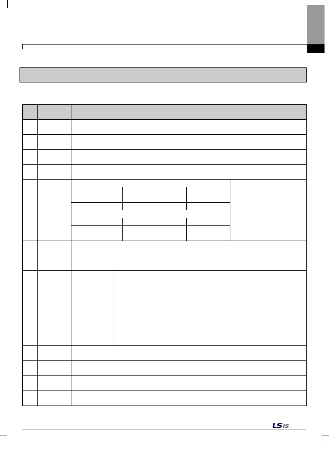
Specifications
Temperature
Temperature
Humidity
Humidity
Intermittent Vibra tion
- Frequency
Acceleration
Amplitude
Counts
5≤ f <8.4Hz
−
3.5mm
8.4≤ f ≤ 150Hz
9.8m/s2(1G)
Continuous Vibration
Frequency
Acceleration
Amplitude
5≤ f <8.4Hz
−
1.75mm
8.4≤ f ≤ 150Hz
4.9m/s2(0.5G)
wave Pulse (three counts in X, Y, Z directions,
respectively)
Standard
Discharge:
(IEC61000-4-2)
Noise
(IEC61000-4-3)
Module
Communication Interface
Voltage
2kV
1kV
Environment
Altitude
Level
Method
Chapter 2 Specifications
Chapter2 Specifications
2.1 General specifications
The general specifications of the temperature controller module (XBF-LD02S) are shown in Table 2.1.
No. Item Specification
Related
1
2
3
4
5
6
Working
Storage
Working
Storage
Vibration
Resistance
Shock
Resistance
0 ~ 55°C
−25 ~ +70 °C
5 ~ 95%RH, no dew condensation.
5 ~ 95%RH, no dew condensation.
• Ma x Shock A cceleration 147 m/s2(15G)
• Applied Time: 11ms
• Pulse Waveform: Sine Half-
Square-wave
Impulse Noise
AC: ±1,500V, DC: ±900V,
−
−
X, Y, Z
Each
Direction
10
counts
IEC61131-2
(IEC60068-2-6)
IEC61131-2
(IEC60068-2-27)
Inside LSIS
Test Specifications
7
Resistance
Surrounding
8
Working
Pollution
Cooling
9
10
11
Electrostatic
Noise
Radiation Field
Past Transient
/ Burst
Noise
Voltage: 4kV (Contact Dis charge)
80 ~ 1000MHz, 10V/m
Classification
No Corrosive Gas or Dust
[Table 2.1] General Specifications
Power
2,000m or below
2 or below
Natural Air Cooling
Digital/Analogue Input/Output
IEC61131-2
IEC61131-2
IEC61131-2
(IEC61000-4-4)
2-1
Page 15
technical Commission)An international private organization which promotes international
field of electric/electronic technology, publishes international standards, and operates
level represents the level of pollution in the working environment, which determines the insulation
Chapter 2 Specifications
Remark
1) IEC(International Electrocooperation for standardization in the
the conformity assessment programs.
2) Pollution Level: Pollution
performance of a device. Pollution level of 2 refers to a state where only non-conductive pollution occurs. However, in case
of condensation, a temporary condensation may occur.
3) Use of portable radio is restricted as it may affect the accuracy of the load cell module. If a radio must be used, please keep
the safe distance (50 cm).Here, the safe distance includes the distance from the input cable connected to the module.
2-2
Page 16
Items
Specifications
Input Channel
2 Channel (Insulation between Channels)
Load Cell Input Voltage
5VDC±5%, (8 per 350Ω load cell channel)
Resolution
1/40000
Analog Input Range
0.0~6.0㎷
Load Cell Output
Sensitivity
±0.01% or below (nonlinear accuracy, 25℃)
Gain Drift: ±15ppm//℃
Sampling Cycle (per
channel)
Insulation Voltage
(Internal Test
Specifications)
AC 550 V
below
Warm-up time
30 minutes or above
Input Connector
8 pins Connector(CH0)/10 pins Connector(CH1)
IO Occupation Points:
Fixed type:64 points
7: XBM type, XBC/XEC-SU type
10: XBC/XEC-H type, XBC/XEC-U type
DC 5 V(internal),
DC 20.4 V~28.8V(external)
Internal
(DC5V)
External
(DC24V)
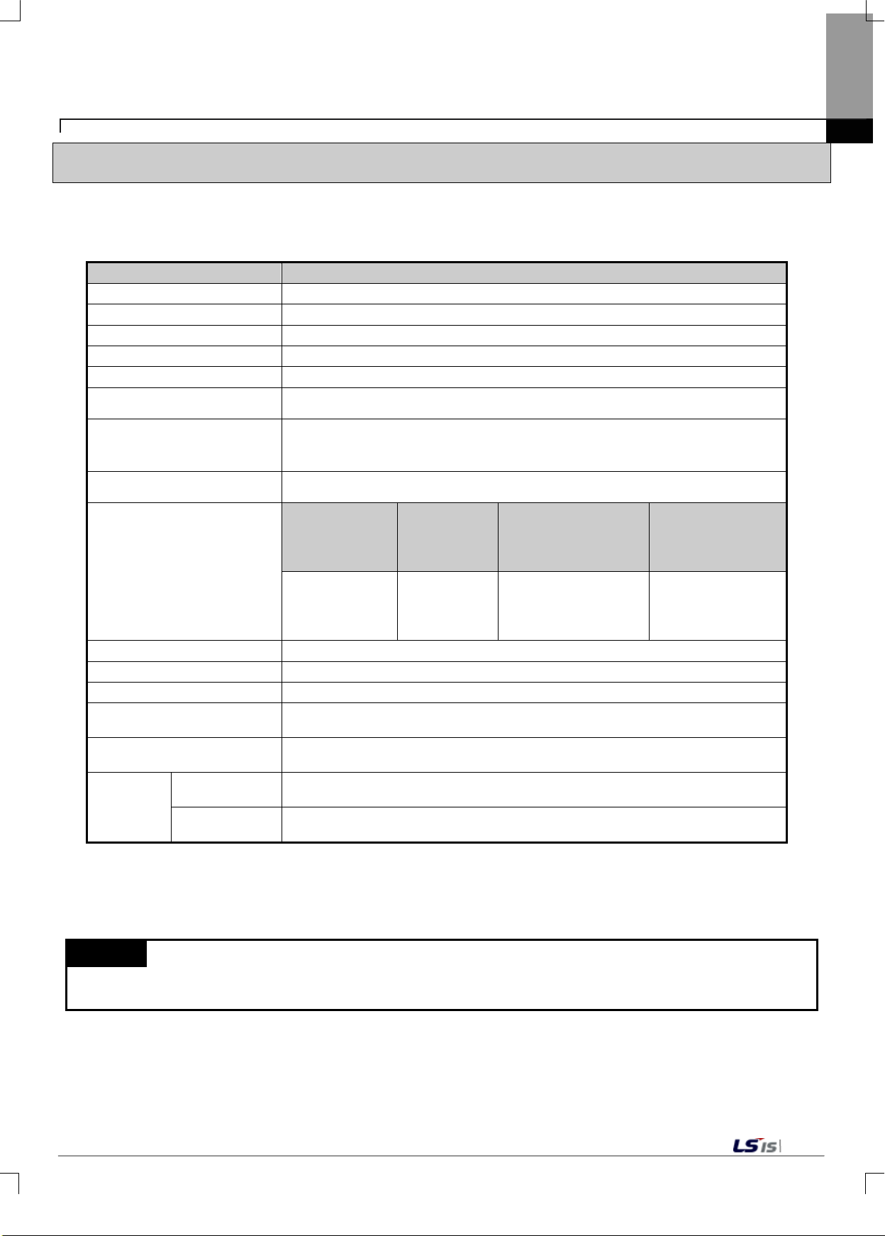
2.2 Performance specifications
2.2.1 Performance specifications of XBF-LD02S module
The performance specifications of the temperature controller module (XBF-LD02S) are shown in Table 2.2.
Load Cell Type Four-wire or Six-wire
0.125㎶(when the rated output of the load cell is 0.0 ~ 1.0㎷/ V)
Chapter 2 Specifications
Input Accuracy
Insulation
Maximum number of units
Power Supply
Power
Consum
ption
Zero Drift: ±0.25㎶/℃
5㎳
Classification
Input T erminal
and Internal
Circuits
110㎃
280㎃
Insulation
Method
Photo
Coupler
Resistance
50/60 Hz 1 minute,
Leakage 10 m A or
Insulation
Resistance
DC500 V,
10 MΩ or above
[Table 2.2] Performance Specification (XBF-LD02S)
Remark
Warm-up time: Calibration or measurement must begin 30 minutes after the power supply is applied.
2-3
Page 17
Displays the H/W operation status of the XBF-LD02S module
Blink; Error
Input Connector of XBF- LD02S Module (CH0)
Load cell input sensor connection
Input Connector (CH1)
Input Connector Of XBF- LD02S Module (CH1)
Load cell input sensor connection
24V Power Supply Uni t Co nn e ction
PE Connection Connector of XBF- LD02S Module
Protective
Chapter 2 Specifications
2.3 Part names and Structure
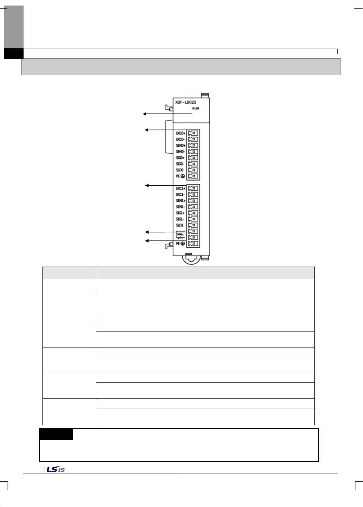
2.3.1 Part names and Structure of XBF-LD02S module
①
②
③
④
⑤
No Details
RUN LED
▶
①
②
On: Module H/W normal
Off: DC 5V failure or Module H/W failure
Input Connector
▶
③
④
⑤
Remark
(1) The use of a separate external power source is recommended for DC power 24V,
2-4
because main units are different output capacity of DC power 24V.
▶
External 24V Connector
▶Externa l 2 4V P ow er S u pply Connector of XBF_L D02S Modul e
PE Connector
▶
Page 18
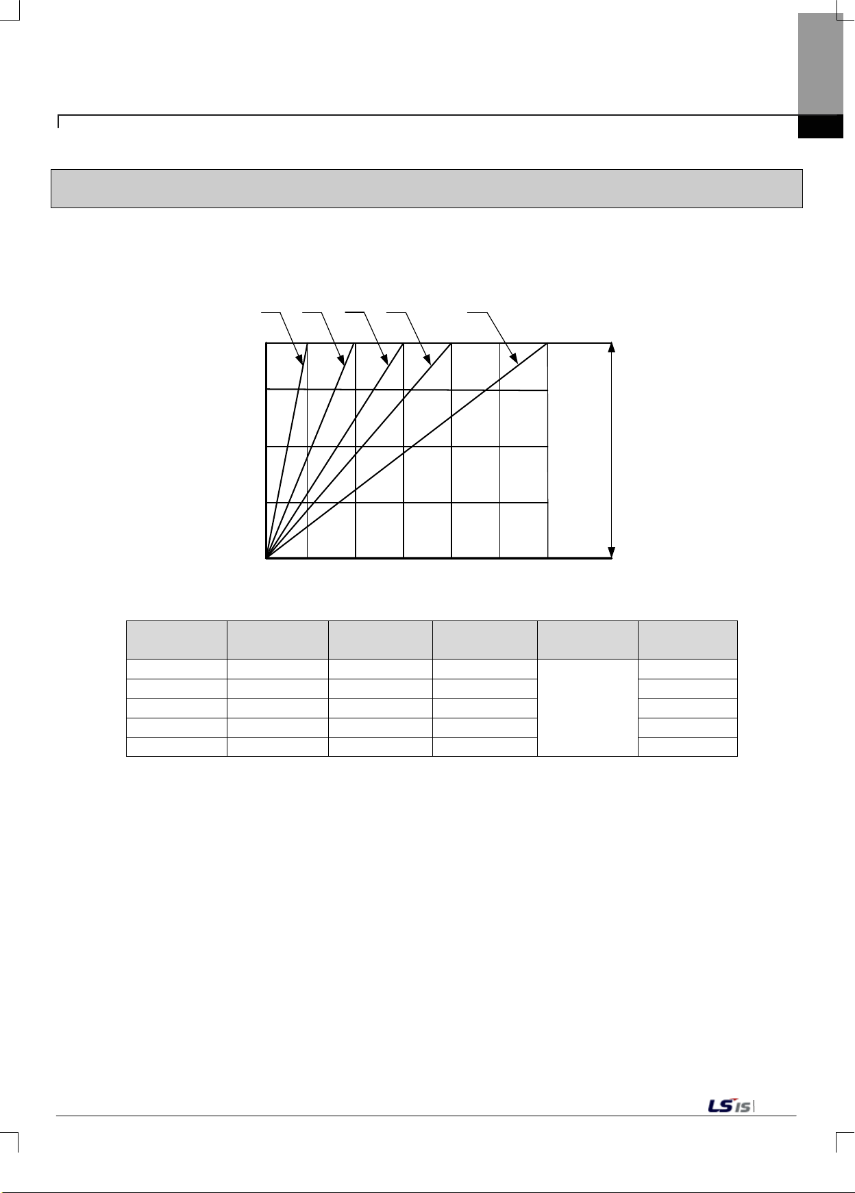
Digital
Conversion Value
40000
0
5mV 10mV
0mV
15mV 20mV 25mV
30mV
20000
Load Cell
Actual Output
Range
(1)
(2)
(3)
(4) (5)
Load Cell
Sensitivity
Maximum
Weight Value
Maximum
Resolution
(1)
1.0V
0㎷
5㎷
0.125㎶
(2)
2.0V
0㎷
10㎷
0.25㎶
(3)
3.0V
0㎷
15㎷
0.375㎶
(4)
4.0V
0㎷
20㎷
0.5㎶
(5)
6.0V
0㎷
30㎷
0.75㎶
2.4 Input conversion charac t er istics
2.4.1 Input area conversion characteristics
1) Data Conversion Characteristics
This section explains the characteristics of the conversion of load cell output signals into digital data.
Chapter 2 Specifications
Zero value is when the digital output value is 0, and the digital output value of the maximum weight is 40,000.
Graph No.
The maximum resolution ref ers to the s ens itivit y which can be ex press ed b y a m inimum unit s cale ( single sc ale)
with respect to the maximum weight value.
2) Relationship between Load Cell Output and Input Sensitivity
If the load cell sensitivity is 2.0 ㎷/V, the input sensitivity of the product is 0.25uV/digit or above.
When designing the system, the following formula must be met.
Example) Number of load cells: 4
Rated load cell capacity: 500 kg:
Rated load cell output: 2mV/V
Single scale: 0.10 kg
Power connected to load cell: 5V (= 5,000 mV)
According to the formula, (5000 mV* 2mV * 0.1Kg)/(500Kg * 4) = 0.5≥ 0.25 ㎶
Since the calculated value is larger than 0.25 ㎶, the weight system design is acceptable.
Zero Value
Digital Output
0~40000
2-5
Page 19
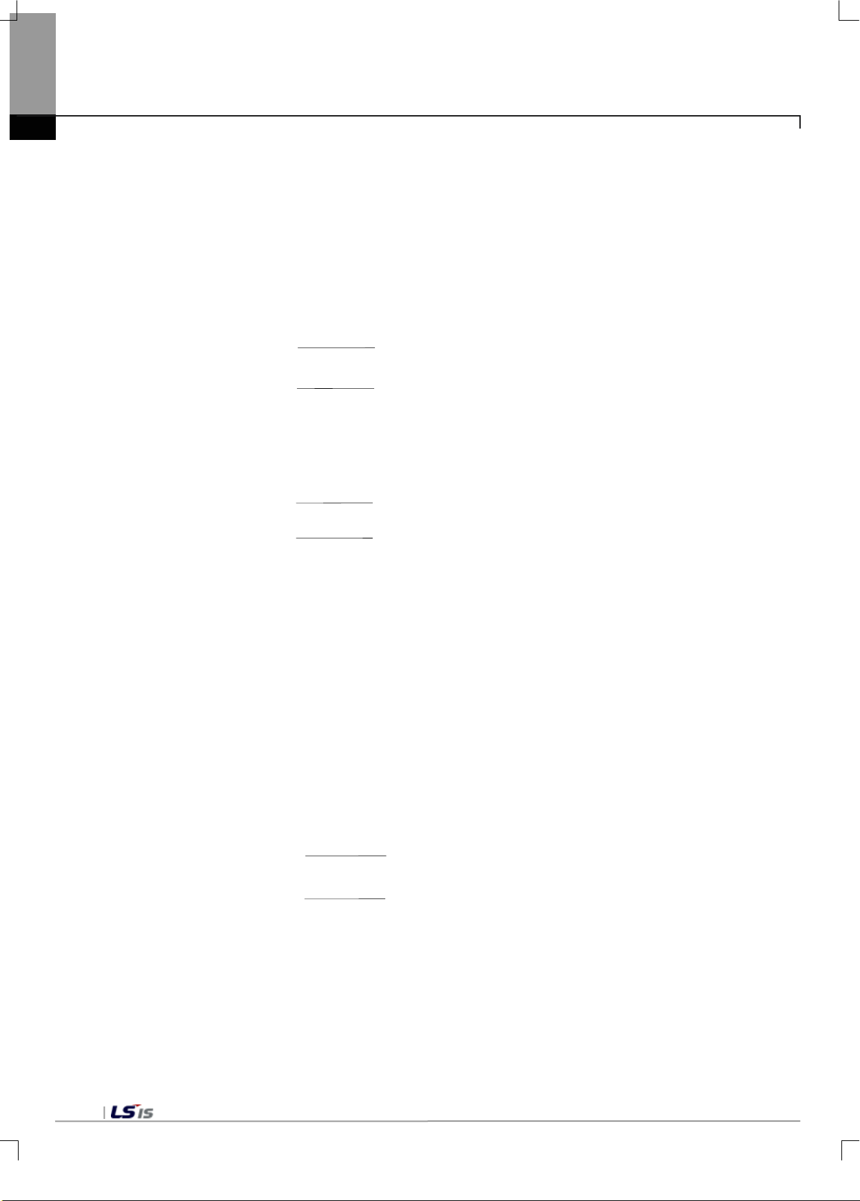
0.25μV/℃
2mV/V x 5V
Zero Drift = ±40000 x
x Δt
0.25μV/℃
2mV/V x 5V
Zero Drift = ±40000 x
X (55℃-25℃)
Zero Drift =
±30 (±
0.075%)
15ppm/℃
1000000
Gain Drift = ±40000 x
x Δt
15ppm/℃
1000000
Gain Drift = ±40000 x
X (55℃-25℃)
Gain Drift =
±18
(
±0
.045%)
0.25μV
/℃
2mV/V x 5V
Zero Drift = ±40000 x
x
Δt
0.
25μV/℃
2mV/V x 5V
Zero Drift = ±40000 x
X (0℃-25℃)
Zero Drift
=
±25 (±
0.0625
%)
Chapter 2 Specifications
2.4.2 Accur acy
The accuracy of a load cell input module changes depending on the ambient temperature.
2.4.2.1 When the ambient temperature is 55℃
If the load cell output s ensitivity is 0.0~ 2.0mV/V, the ambient temper atur e during calibration is 25℃,
and the current ambient temperature is 55℃, accuracy is calculated as follows.
(Δt: current ambient temperature - ambient temperature during calibration)
1) Zero Drift
2) Gain Drift
3) Integrated Accuracy
Integrated Accuracy = Nonlinear Accuracy + Zero Drift + Gain Drift
= ±4(0.01%) ± 30(0.075%) ± 18(0.045%) = ±52(0.13%)
2.4.2.2 When the ambient temperature is 0℃
If the load cell output s ensitivity is 0.0~ 2.0mV/V, the ambient temper atur e during calibration is 25℃,
and the current ambient temperature is 0℃, accuracy is calculated as follows.
1) Zero Drift
2-6
Page 20
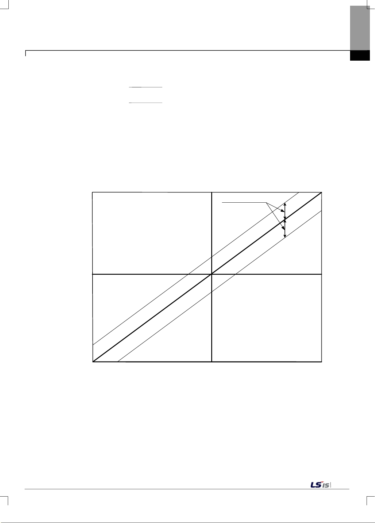
15
ppm/℃
1000000
Gain Drift = ±40000 x
x
Δt
15ppm/℃
1000000
Gain Drift = ±40000 x
X (0℃-25℃)
Gain Drift = ±15 (±0.0375%)
Digital
Conversion
Value
Load Cell Output Value
0
40000
20000
5mV 10mV0mV
Integrated
Accuracy
Range
2) Gain Drift
3) Integrated Accuracy
Integrated Accuracy = Nonlinear Accuracy + Zero Drift + Gain Drift
= ±4(0.01%) ± 25(0.0625%) ± 15(0.0375%) = ±44(0.11%)
Chapter 2 Specifications
[Accuracy Diagram]
2-7
Page 21
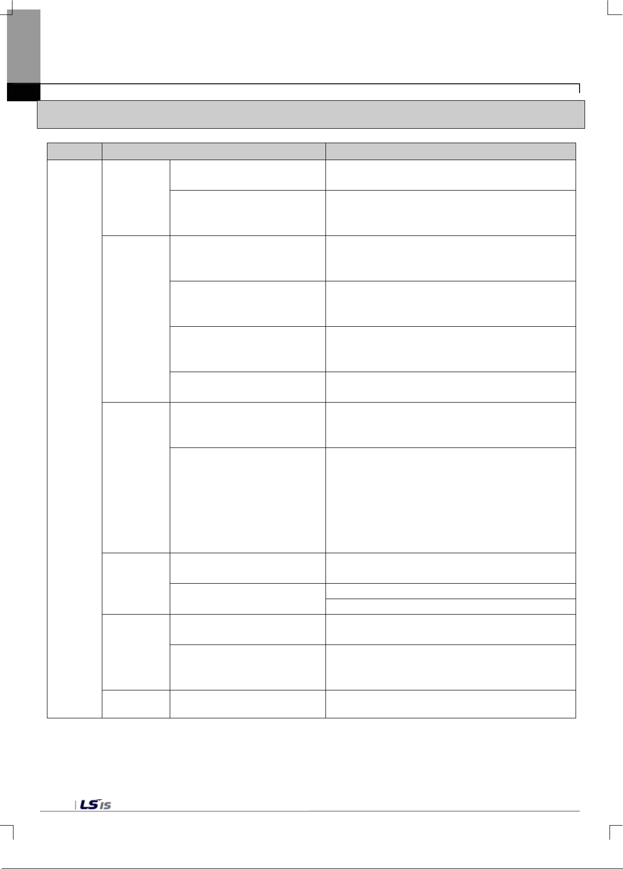
measurement range of the weight system.
environment such as temperature.
displays the average value of the sum as digital data.
displays the average value of the sum as digital data.
average value of the sum as digital data.
Function
value is safe.
temperature change.
weight of the container.
inputs.
It displays (L) L Status Flag.
It displays (H) H Status Flag.
Maintenance Function
weight measured while running the input channel.
request flag is turned on.
Auxiliary
Functions
Chapter 2 Specifications
2.5 Functions
Item Function Details
Load Cell
Input
Function
Calibration
Function
Input
Processing
Zero
Processing
2-Point Calibration Function
1-Point Calibration Function
Moving Average Function
Moving/Count Average Function
Moving/Time Average Function
Stable Status Determination
Zero Tracking Function
Zero Setting, Reset Function
Before measuring the actual weight, it calibrates the
2-Point Calibration Function: calibrates only the zero
point depending on changes in the surrounding
It accumulates the input values of a designated
channel in accordance with the set counts, and
It accumulates the moving averages of a designated
channel in accordance with the set counts, and
It accumulates the moving averages of a designated
channel for the set amount of time, and displays the
It determines whether the status of the tot al wei ght
It adjusts zero output values in accordance with
changes of the surrounding environment, such as
It temporarily adjusts zero output values when 0 is not
output even after 2-point calibration due to changes of
the surrounding environment such as gathering of
foreign matters around the pallet caused by using the
load cell for a long time. When using a container
(Tare), you can also use this function to remove the
Alarm
Function
Output
Maintenance
Function
2-8
HL Alarm Function
Flag Display Function
Maximum·Minimum Value
Output Value Maintenance
Function
Free Fall calibration Function It automatically calibrates free fall values.
Processes alarm by defining the HH, H, L, LL of
It displays the maximum / minimum values of the total
It temporarily maintains the output value of the total
weight. It is executed only when the output sta tus
Page 22
Wire specifications
Lower
Upper
0.18mm2 (AWG24)
1.5 mm2 (AWG16)
Chapter 3 Installation and Wiring
3.1 Installation
3.1.1 Installation environment and suggestions
Please not the following items to ensure the reliability and stability of the system.
1) Environmental conditions
(1) Installed on the waterproof and dust resistant control panel.
(2) Protected from continuous impact (shock) and vibration.
(3) Not exposed to direct sunlight.
(4) Where there is no dew condensation caused by rapid changes in temperature.
(5) Where the temperature is kept at 0 -55℃
2) Installation
(1) Make sure that wiring waste does not go into the PLC when dr i lling and wir ing operations are conducted.
(2) Installed in a location that is good for manipulation.
(3) Not installed in the same panel with high voltage equipment.
(4) The distance between duct and surrounding modules should be kept at least more than 50 ㎜ away.
(5) Grounded in a place with favorable ambient noise environment.
(6) Installed so that wind from a cooling fan will not come in direct contact with the inside of the panel.
3) Handling precautions
(1) Handling precautions from the opening of the module and its installation are described.
(2) Do not drop or apply strong impact.
(3) Do not remove PCB from the case. This may cause a failure.
(4) Make sure that foreign matters such as wiring waste do not go into the upper part of the module in
distributing wires.
(5) Do not install or remove of the module when the power is turned on.
Chapter 3 Installation and Wiring
3.1.2 Wiring
1) Wiring precautions
(1) Do not leave AC power line close to the external input signal line of the module. It should maintain
enough distance to avoid effects from the induction noise or surge occurring from the AC side.
(2) The wires should be selected in consideration of the ambient temperature and allowable current, and the
wire specifications are as follows.
(3) Use a shielded cable to connect the load cell. Disconnect the wire from high-noise voltages or AC power
wires using a shielded cable.
(4) If the wire is too close to hot device or material or comes in direct contact with oil for a long time, it can
make a short cut and therefore lead to damage or malfunction.
(5) Check the polarity when wiring terminal blocks.
(6) If the wire is distributed along with high voltage line and power line, it causes a induction failure, thereby
contributing to malfunction or failure.
(7) Be sure to use the same power supply as that of XGB basic unit for the external DC24V power wiring.
If the external DC24V power of the module is Off/On when the XGB basic unit power is On, it can cause
abnormalities in the temperature input value.
3-1
Page 23
Chapter 3 Installation and Wiring
3.2 Wiring
3.2.1 Input area wiring
Load cell input module offers a terminal that can connect analog input signals to a 24V power supply and FG.
And it supports 4 lines type and 6 lines type as a load cell wiring method.
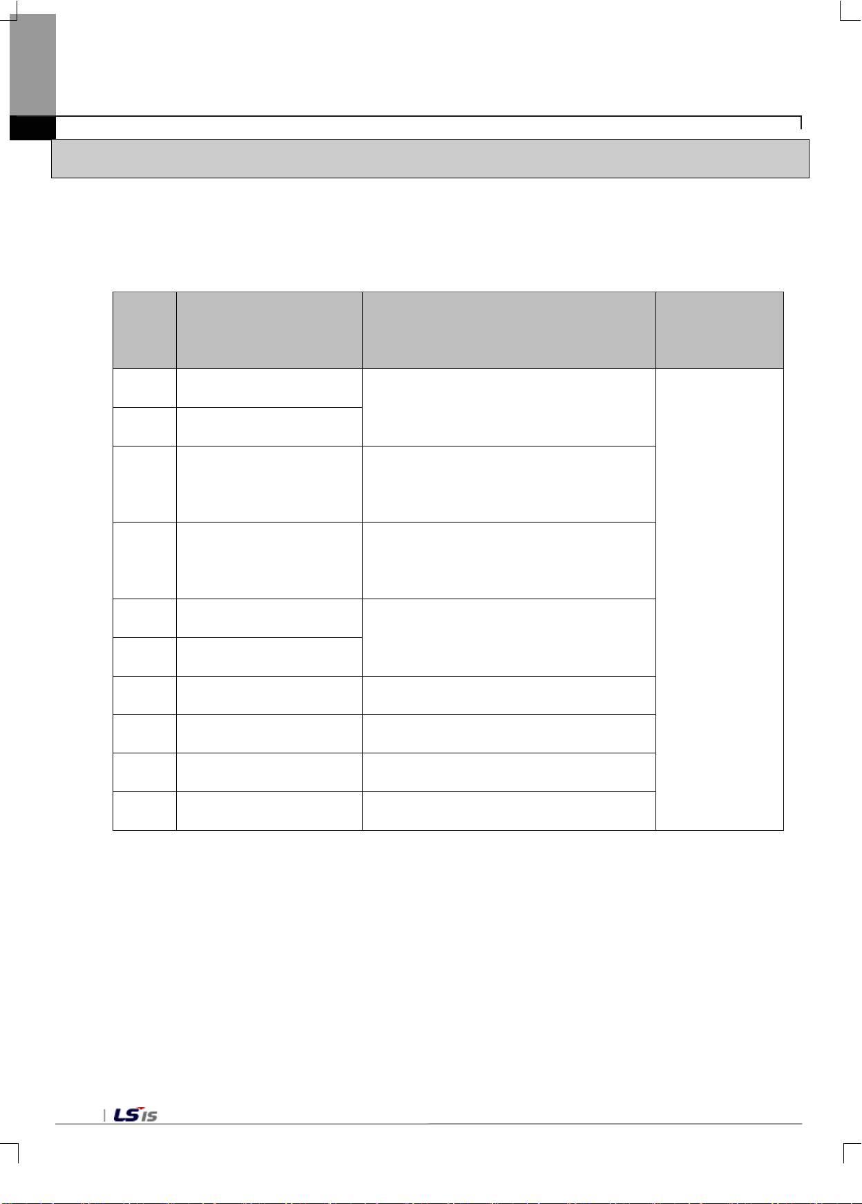
Terminal
Function Description
name
EXCx+ Load cell applied voltage(+)
EXCx- Load cell applied voltage(-)
SENx+ Load cell sensing input(+)
SENx- Load cell sensing input(-)
SIGx+ Load cell signal input(+)
SIGx- Load cell signal input(-)
SLDx Shield Connect shield wires of the load cell cable
Voltage supplied to the load cell in the
module(DC5V)
Signal for measuring the voltage drop in
EXCx+ side of the load cell cable
Signal for measuring the voltage drop in
EXCx- side of the load cell cable
Load cell output voltage
Remarks
x: Input channel
number
3-2
DC24V 24VDC power + External 24V supply power(24V)
GND 24VDC power GND External 24V supply power(GND)
PE Grounding External grounding
Page 24
EXC 0+
SEN 0+
EXC 0-
SEN 0-
SIG 0-
SIG 0+
PE
SLD 0
EXC 1+
SEN 1+
EXC 1-
SEN 1-
SIG 1-
SIG 1+
PE
SLD 1
DC24V
+
DC s ourc e
(DC24V)
-
RUN
Load Cell
350Ω X 4
350Ω X 4
XBF-LD02S
Load Cell
F
EXC 0+
SEN 0+
EXC 0-
SEN 0-
SIG 0-
SIG 0+
PE
SLD 0
EXC 1+
SEN 1+
EXC 1-
SEN 1-
SIG 1-
SIG 1+
PE
SLD 1
DC24V
+
DC s ourc e
(DC24V)
-
RUN
Load Cell
350Ω X 4
350Ω X 4
XBF-LD02S
Load Cell
F
LD02S
Chapter 3 Installation and Wiring
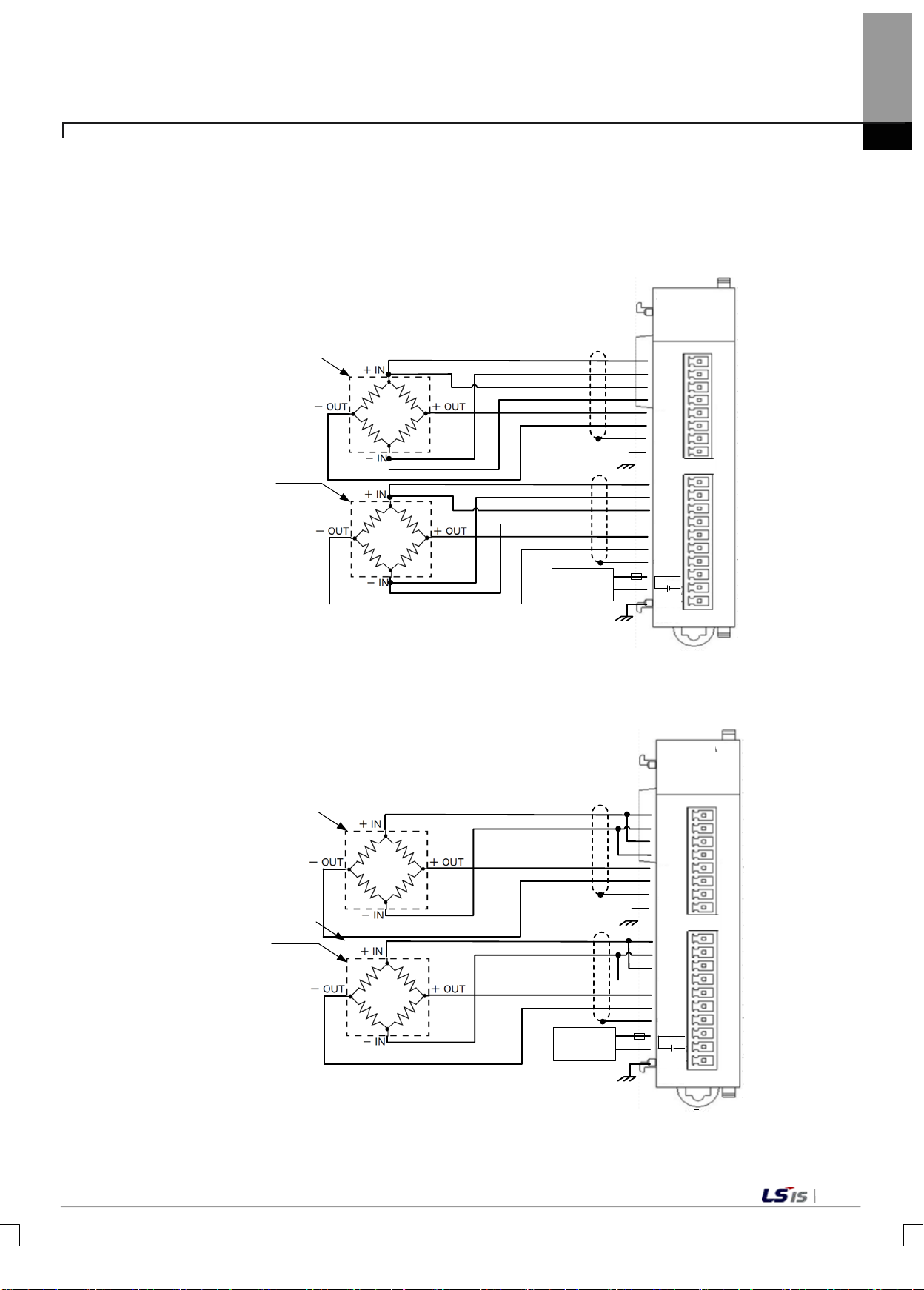
1) 6 lines type load cell
6 lines type connection method is recommended for analog input terminals of the load cell input module. The 6
lines type can com pens ate f or ex ternal c hanges s uch as changes in line resistanc e since EXC+/- si gnal is fed
back to SEN+/- sign al f rom the load c el l. I t can further decrease errors than 4 line s t ype if a long c able is us ed.
The figure below shows an example of wiring for 6 lines type.
2) 4 lines type load cell
4 lines type has no sense output. In case of using 4 lines type, EXC+/- should be connected to SEN+/-.
The figure below shows an example of wiring for 4 lines type system.
LD02S
3-3
Page 25
EXC 0+
SEN 0+
EXC 0-
SEN 0-
SIG 0-
SIG 0+
PE
SLD 0
EXC 1+
SEN 1+
EXC 1-
SEN 1-
SIG 1-
SIG 1+
PE
SLD 1
DC24V
DC s ourece
(DC24V)
+
-
Junct ion Box
RUN
Load Cell
350Ω X 4
350Ω X 4
350Ω X 4
350Ω X 4
XBF-LD02S
Load Cell
Load Cell
Load Cell
F
LD02S
Chapter 3 Installation and Wiring
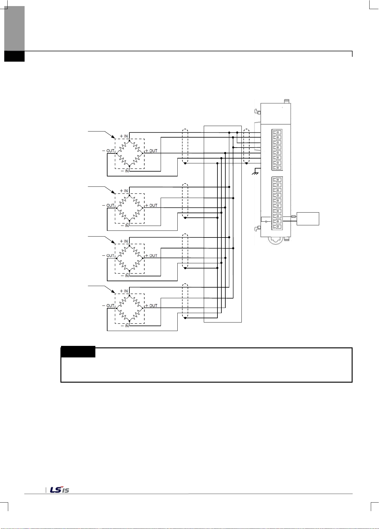
3) Load cell parallel connection (4 lines type load cell)
Load cell input module can configure a hopper sc ale system by supporting the par all el c o nnec t ion of up to
8 load cells. The following figure shows an example of the parallel connection.
Remark
(1) The use of a separate external power source is recommended for DC power 24V,
because main units are different output capacity of DC power 24V.
3-4
Page 26
Device name
Word
Bit
U0y.00.0
_0y_ERR
Module error
U0y.00.F
_0y_RDY
Module Ready
U0y.01
U0y.01.0
_0y_CH0_RUN
Channel 0 running
U0y.01.8
_0y_CH0_CALMOD
Channel 0 calibration model
U0y.01.9
_0y_CH1_CALMOD
Channel 1 calibration mode
U0y.01.E
_0y_CH0_ERR
Channel 0 error
U0y.01.F
_0y_CH1_ERR
Channel 1 error
U0y.02
U0y.02.2
_0y_CH0_ZERO
Channel 0 ZERO status
U0y.02.3
_0y_CH1_ZERO
Channel 1 ZERO status
U0y.02.4
_0y_CH0_COMPLETE
Channel 0 weigh complete status
U0y.02.7
_0y_CH0_SP2
Channel 0 step 2 status
U0y.02.8
_0y_CH0_SP3
Channel 0 step 3 status
U0y.02.9
_0y_CH0_UNDER
Channel 0 lack status
U0y.02.B
_0y_CH1_SP1
Channel 1 step 1 status
U0y.02.C
_0y_CH1_SP2
Channel 1 step 2 status
U0y.02.D
_0y_CH1_SP3
Channel 1 step 3 status
U0y.02.E
_0y_CH1_UNDER
Channel 1 lack status
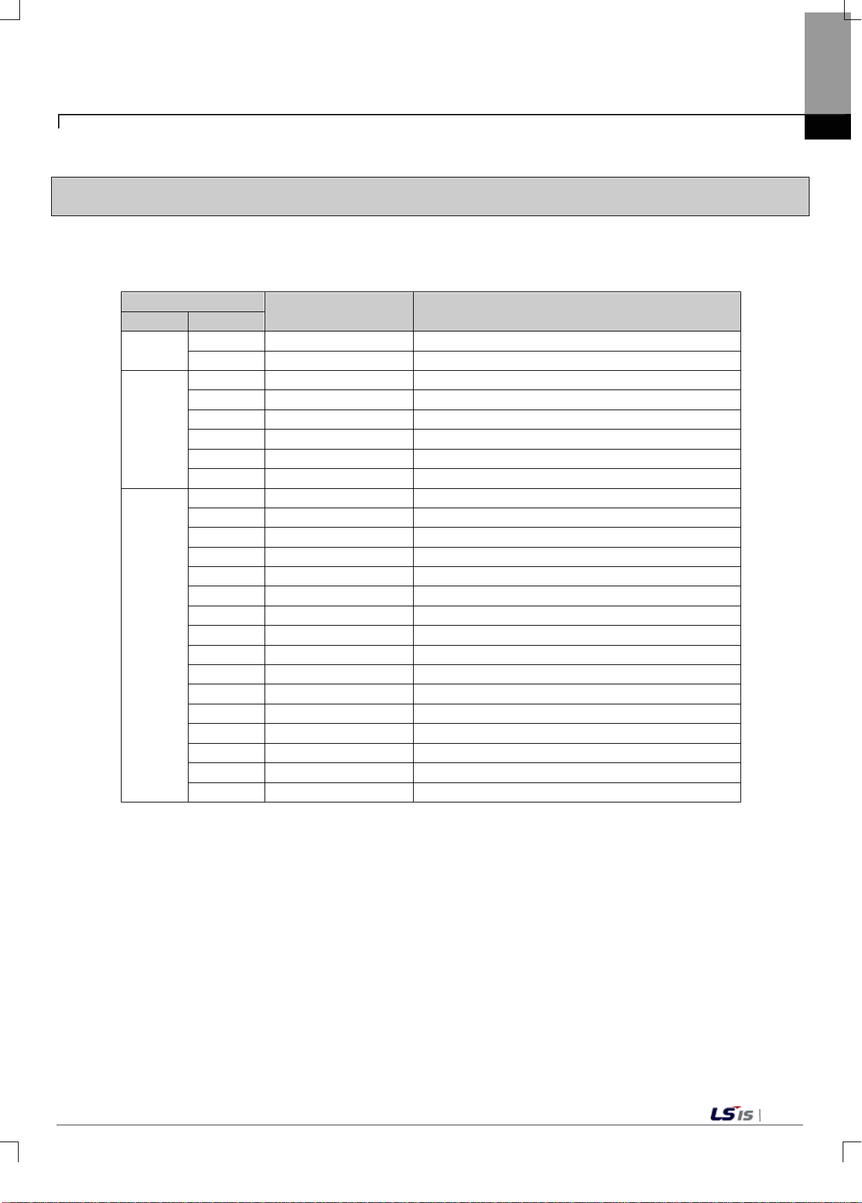
Chapter 4 Memory Structure(for XBC)
4.1 U Device area
U device area of the load cell input module is shown in Table 4.1.
4.1.1 U Device area
Symbol name Description
U0y.00
U0y.01.1 _0y_CH1_RUN Channel 1 running
Chapter 4 Memory Structure(for XBC)
U0y.02.0 _0y_CH0_STBL Channel 0 stable status
U0y.02.1 _0y_CH1_STBL Channel1 stable st at us
U0y.02.5 _0y_CH1_COMPLETE Channel1 weigh complete stat us
U0y.02.6 _0y_CH0_SP1 Channel 0 step 1 status
U0y.02.A _0y_CH0_OVER Channel 0 over status
U0y.02.F _0y_CH1_OVER Channel 1 over status
4-1
Page 27
Device name
Word
Bit
U0y.03.0
_0y_CH0_ZCALEND
Channel 0 zero calibration comple te
U0y.03.1
_0y_CH1_ZCALEND
Channel 1 zero calibration co mple te
U0y.03.4
_0y_CH0_CALEND
Channel 0 calibration save co mplet e
U0y.03.5
_0y_CH1_CALEND
Channel1 calibration save co mple te
U0y.04
U0y.04.0
_0y_CH0_ZSET
Channel 0 zero setting status
U0y.04.1
_0y_CH1_ZSET
Channel 1 zero setting status
U0y.04.3
_0y_CH1_ZRST
Channel 1 zero reset status
U0y.04.4
_0y_CH0_TSET
Channel 0 tare setting status
U0y.04.5
_0y_CH1_TSET
Channel 1 tare setting status
U0y.04.8
_0y_CH0_MINMAXHLD
Channel 0 Minmax Hold Status
U0y.04.9
_0y_CH1_MINMAXHLD
Channel1 Minmax Hold Status
U0y.04.A
_0y_CH0_NEARZERO
Channel 0 near zero status
U0y.04.D
_0y_CH1_GRSMINUS
Channel 1 gross weight negati ve status
U0y.04.E
_0y_CH0_NETMINUS
Channel 0 net weight negative status
U0y.04.F
_0y_CH1_ NETMINUS
Channel 1 net weight negative status
U0y.05
U0y.05.0
_0y_CH0_HOOR
Channel 0 upper alarm occurrence
U0y.05.2
_0y_CH0_LOOR
Channel 0 upper alarm occurrence
U0y.05.3
_0y_CH1_LOOR
Channel 1 lower alarm occurrence
U0y.05.8
_0y_CH0_HHOORSTAT
Channel 0 high high stat us
U0y.05.9
_0y_CH0_HOORSTAT
Channel 0 high status
U0y.05.B
_0y_CH0_LLOORSTAT
Channel 0 low low status
U0y.05.C
_0y_CH1_HHOORSTAT
Channel 1 hgh high status
U0y.05.D
_0y_CH1_HOORSTAT
Channel 1 high status
U0y.08
_01_CH1_GWDATA_L
Channel 1 gross weight value (Lower)
U0y.09
_01_CH1_GWDATA_H
Channel 1 gross weight value (Upper)
U0y.10
_01_CH0_ADDATA_L
Channel 0 tare weight value (Lower)
U0y.13
_01_CH1_ADDATA_H
Channel 1 tare weight value (Upper)
U0y.14
_01_CH0_NETDATA_L
Channel 0 net weight value (Lower)
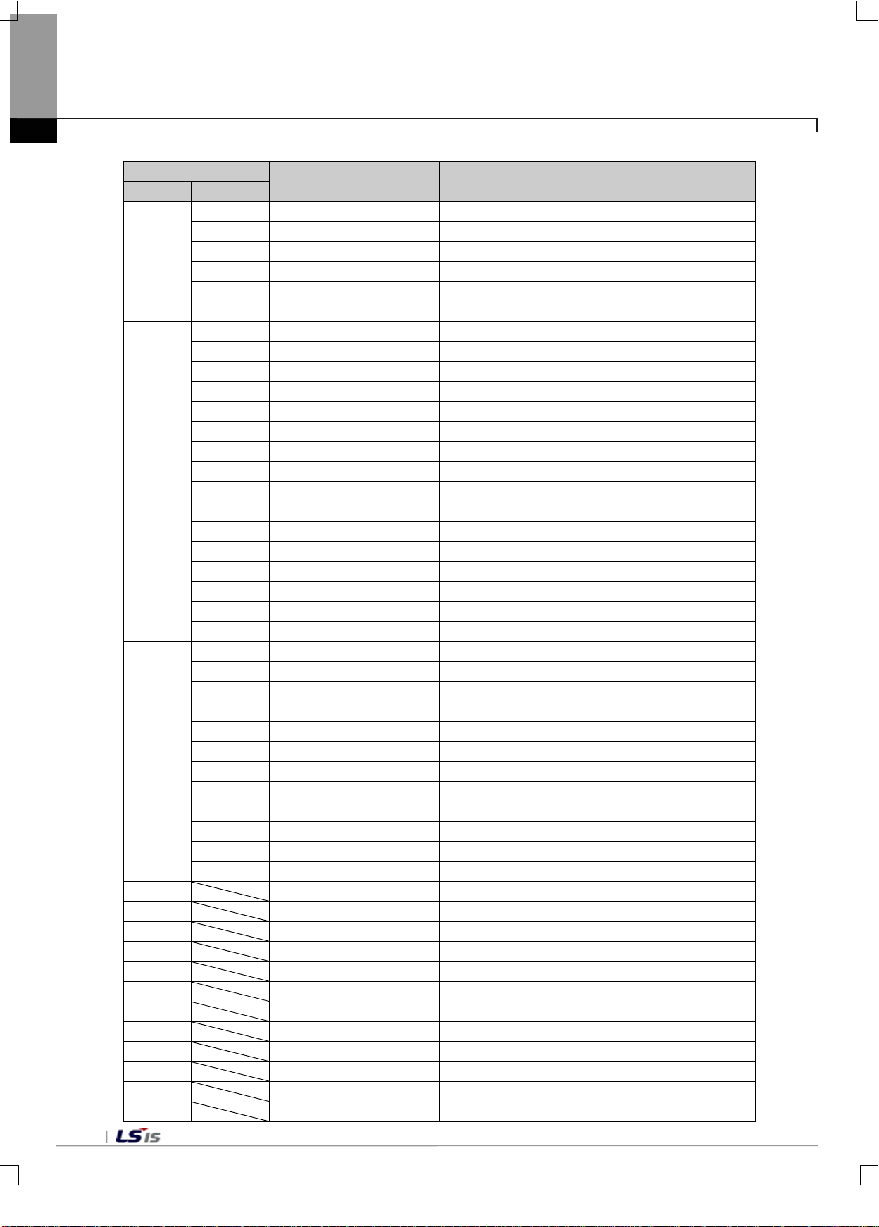
Chapter 4 Memory Structure (for XBC)
Symbol name Description
U0y.03
U0y.03.2 _0y_CH0_SCALEND Channel 0 span calibration complete
U0y.03.3 _0y_CH1_SCALEND Channel 1 span calibrati on co mple te
U0y.04.2 _0y_CH0_ZRST Channel 0 zero reset status
U0y.06
U0y.07
U0y.04.6 _0y_CH0_WEIGHTHLD Channel 0 output maintenance status
U0y.04.7 _0y_CH1_WEIGHTHLD Channel 1 output maintenance status
U0y.04.B _0y_CH1_NEARZERO Channel 1 near zero status
U0y.04.C _0y_CH0_GRSMINUS Channel 0 gross weight negative status
U0y.05.1 _0y_CH1_HOOR Channel 1 upper alarm occurrence
U0y.05.A _0y_CH0_LOORSTAT Channel 0 low status
U0y.05.E _0y_CH1_LOORSTAT Channel 1 low status
U0y.05.F _0y_CH1_LLOORSTAT Channel 1 low low status
_01_CH0_GWDATA_L Channel 0 gross weight value (Lower)
_01_CH0_GWDATA_H Channel 0 gross weight value(Upper)
U0y.11
U0y.12
U0y.15
U0y.16
U0y.17
4-2
_01_CH0_ADDATA_H Channel 0 tare weight value (Upper)
_01_CH1_ADDATA_L Channel 1 tare weight value(Lower)
_01_CH0_NETDATA_H Channel 0 net weight value (Upper)
_01_CH1_NETDATA_L Channel 1 net weight value (Lower)
_01_CH1_NETDATA_H Channel 1net weight value(Upper)
Page 28
Device name
Word
Bit
U0y.18
_01_CH0_GWMAX_L
Channel 0 gross weight maximum value(Lower)
U0y.19
_01_CH0_GWMAX_H
Channel 0 gross weight maximum value (Upper)
U0y.22
_01_CH1_GWMAX_L
Channel1 gross weight maximum value(Lower)
U0y.23
_01_CH1_GWMAX_H
Chanel 1 gross weight maximum value(Upper)
U0y.24
_01_CH1_GWMIN_L
Channel 1 gross weight minimum value(Lower)
U0y.27
_01_CH1_CUR_FFVAL
Channel 1 current free fall value
U0y.28
_01_ECODE
Error code
U0y.29
_01_CH0_CAL1REQ
Channel 0 1-point calibration mode requ est
U0y.29.1
U0y.29.2
U0y.29.3
U0y.30
U0y.30.0
_01_CH0_ZCALREQ
Channel 0 zero-point calibration mode request
_01_CH1_ZCALREQ
Channel 1 zero calibration request
U0y.30.3
U0y.30.4
_01_CH0_CALSTORE
Channel 0 calibration value storage request
U0y.30.5
_01_CH1_CALSTORE
Channel 1 calibration value storage request
U0y.31
U0y.31.0
_01_CH0_ZSETREQ
Channel 0 zero setting request
U0y.31.2
U0y.31.3
_01_CH1_ZRSTREQ
Channel 1 zero reset request
U0y.31.4
_01_CH0_TAREREQ
Channel 0 tare setting
_01_CH1_TAREREQ
Channel 1 tare setting
U0y.31.6
U0y.31.7
U0y.31.8
U0y.31.9
_01_CH1_MAXMINREQ
Channel 1 Minmax Hold Request
_01_CH0_SEQREQ
Channel 0 sequential control request
U0y.31.C
U0y.31.D
U0y.20
U0y.21
U0y.25
U0y.26
U0y.29.0
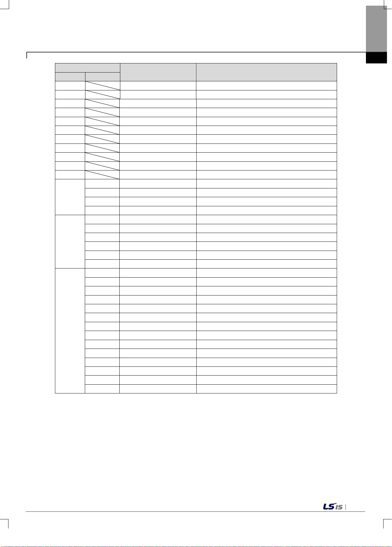
Chapter 4 Memory Structure(for XBC)
Symbol name Description
_01_CH0_GWMIN_L Channel 0 gross weight minimum value(Lower)
_01_CH0_GWMIN_H Channel 0 gross weight minimum value(Upper)
_01_CH1_GWMIN_H Channel 1 gross weight minimum value(Upper)
_01_CH0_CUR_FFVAL Channel 0 current free fall value
_01_CH1_CAL1REQ Channel 1 1-point calibration mode request
_01_CH0_CAL2REQ Channel 0 2-point calibration mode request
_01_CH1_CAL2REQ Channel 1 2-point calibration mode request
U0y.30.1
U0y.30.2
U0y.31.1
U0y.31.5
U0y.31.A
U0y.31.B
- Lowercase letter ‘y’ in device name and symbol name represents the number of a slot equipped with
a module.
_01_CH0_SCALREQ Channel 0 span calibration request
_01_CH1_SCALREQ Channel 1 span calibration request
_01_CH1_ZSETREQ Channel 1 z ero set ting request
_01_CH0_ZRSTREQ Channel 0 zero reset request
_01_CH0_HOLDREQ Channel 0 output hold request
_01_CH1_HOLDREQ Channel 1 output hold request
_01_CH0_MAXMINREQ Channel 0 Minmax Hold Request
_01_CH1_SEQREQ Channel 1 sequential control request
_01_CH0_TARERSTREQ Channel 0 tare released command
_01_CH1_TARERSTREQ Channel 1 tare released command
[Table 4. 1] U device area
4-3
Page 29
Word
Word
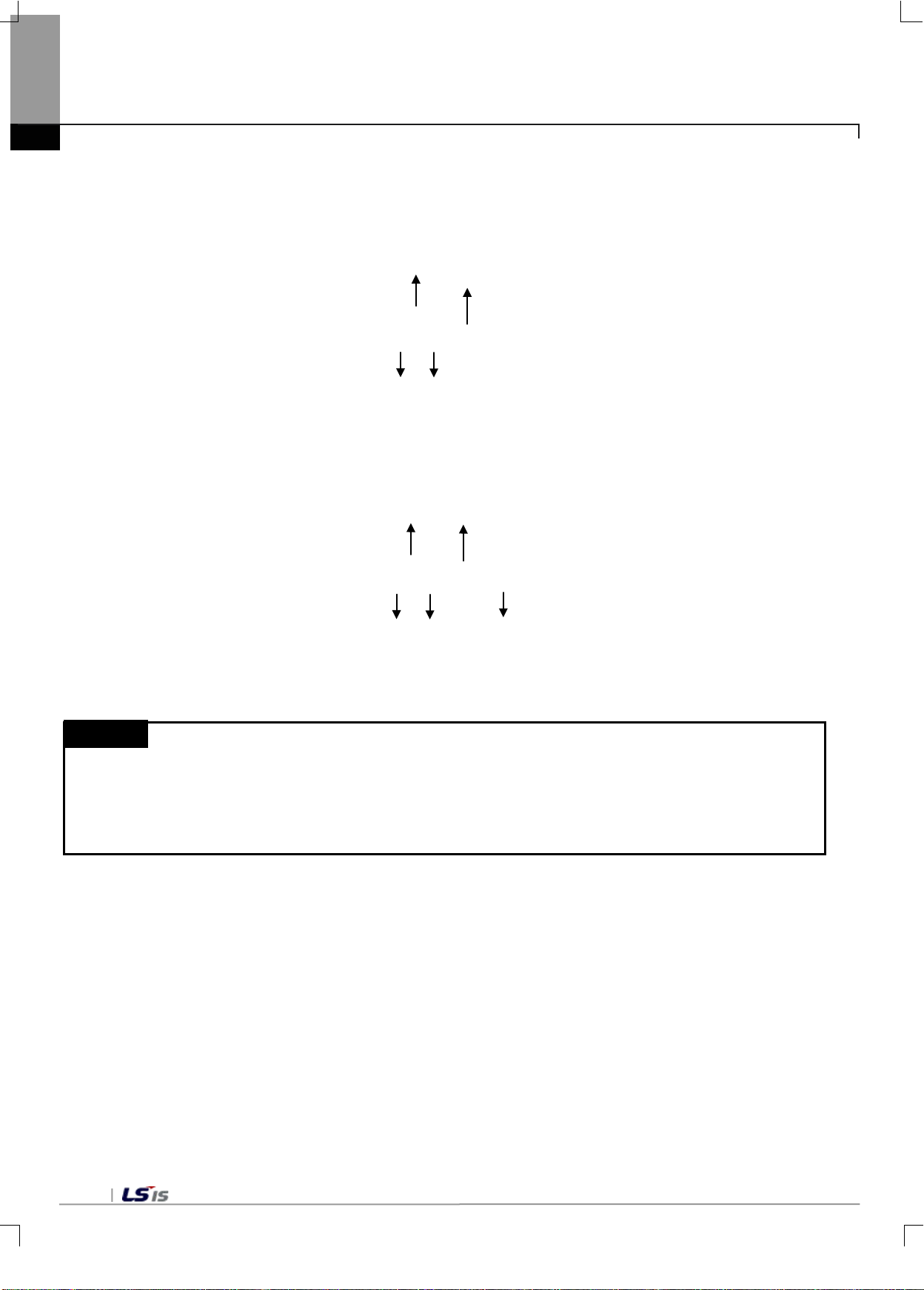
1) Expressed as U04.06 in order to read ‘c hannel 0 gross weight va lue (lower) of the load ce ll mounted on No.0
2) Expressed as U05.27.0 in order to allow ‘channel 0 calibration mode request’ of the temperature controller
mounted on No. 0 base, No. 5 slot. (Expressed as U0A.27.0 if mounted on No. 10 slot)
Chapter 4 Memory Structure (for XBC)
base, No. 4 slot.
Base No.
U 0 4 . 0 6
Device type
Device type
Slot No.
Base No.
U 0 5 . 2 7 . 0
Slot No.
Bit
Remark
U Device : Data read and written at al l times s uch as conversi on data of the Load Cel l module, an d the mem ory
inside the PLC CPU used when r eading or writing sp ecific areas (data to be read per iodically, as defined in the
module) of special/communication muddles in XGB PLC by can is assigned to this area.
Like other devices it can be directly used in general commands such as MOV, CMP and ADD.
(PUT/GET commands should be used in parameter areas of the module.)
4-4
Page 30
0
1
Read/write
WORD
Weighing mode
CPU ↔ LD02S
2
Read/write
WORD
Input channel0 free fall compensat ion cy cle
CPU ↔ LD02S
4
5
6
Read/write
WORD
Input channel0 average proce ssi ng meth od
CPU ↔ LD02S
9
10
11
Read/write
WORD
Input channel1 count average v alue
CPU ↔ LD02S
14
15
16
Read/write
WORD
Input channel0 stable determination time
CPU ↔ LD02S
17
Read/write
WORD
Input channel1 stable determination time
CPU ↔ LD02S
19
20
21
Read/write
WORD
Input channel1 zero tracking time
CPU ↔ LD02S
22
Read/write
WORD
Input channel0 near zero range setting
CPU ↔ LD02S
24
25
26
Read/write
WORD
Input channel0 gross weight HH(Upper)
CPU ↔ LD02S
29
30
31
Read/write
WORD
Input channel0 gross weight L(Upper)
CPU ↔ LD02S
32
Read/write
WORD
Input channel0 gross weight LL(Lower)
CPU ↔ LD02S
34
35
36
Read/write
WORD
Input channel1 gross weight H(Lower)
CPU ↔ LD02S
37
Read/write
WORD
Input channel1 gross weight H(Upper)
CPU ↔ LD02S
Chapter 4 Memory Structure(for XBC)
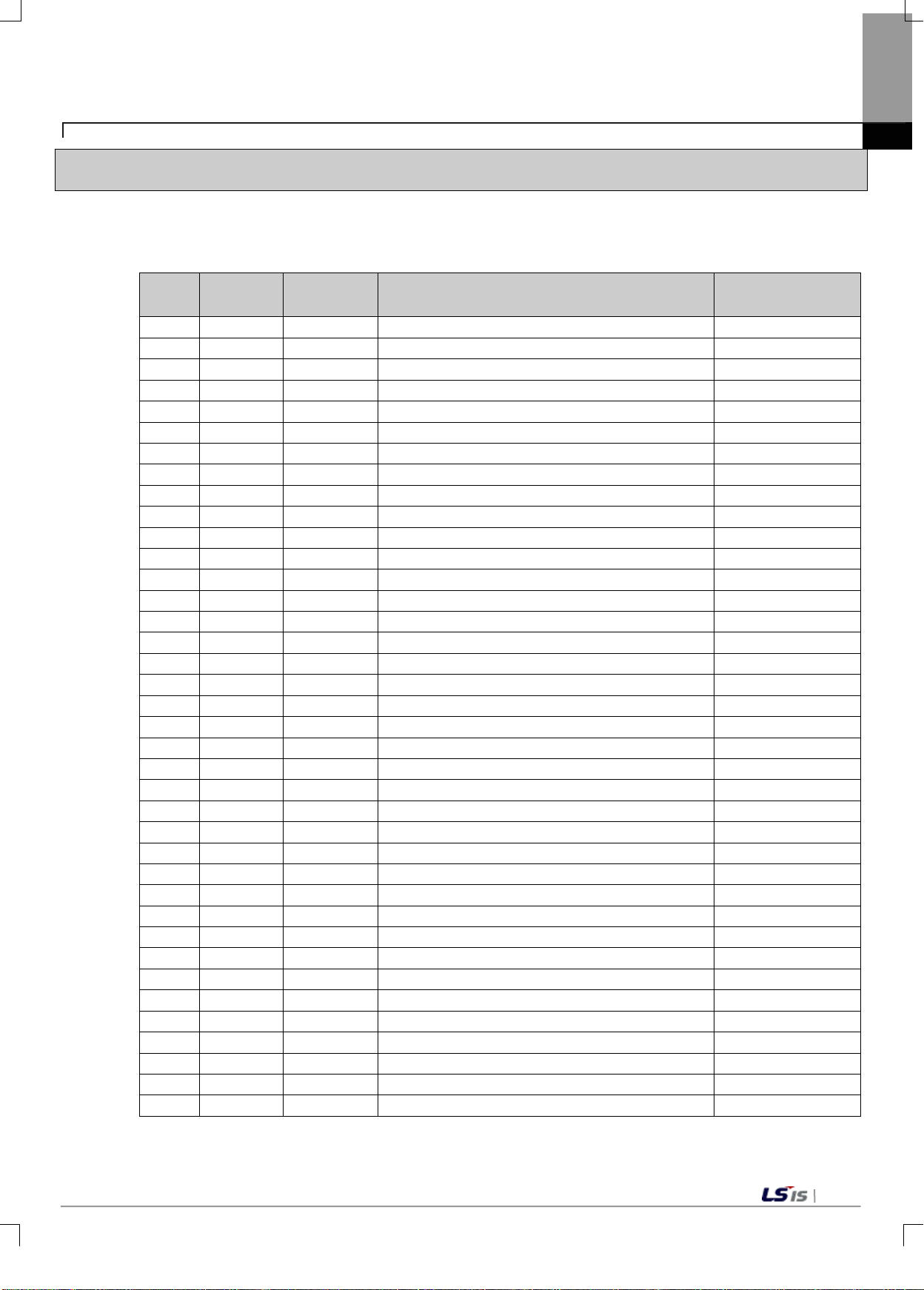
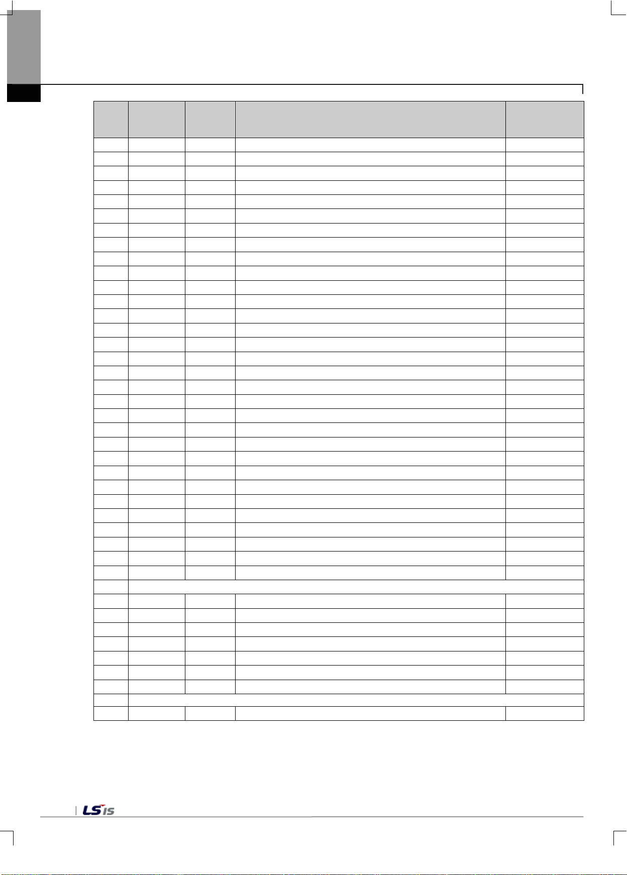
4.2 Parameter setting area(PUT/GET commands used)
- Below are descriptions on how to change parameter values using PUT/GET commands in XG5000 program.
4.2.1 Parameter setting area
No.
3
7
8
12
13
18
Read/
write
Read/write
Read/write
Read/write WORD
Read/write WORD
Read/write WORD
Read/write WORD
Read/write
Read/write WORD
Read/write
Read/write WORD
Read/write WORD
Read/write
Read/write
Read/write WORD
Read/write WORD
Type Description Signal direction
WORD
WORD
WORD
WORD
WORD
WORD
Operating channel
Input channel1 free fall compensat ion cy cle
Input channel0 free fall coefficient CPU ↔ LD02S
Input channel1 free fall coefficient CPU ↔ LD02S
Input channel1 average proce ssi ng meth od CPU ↔ LD02S
Input channel0 moving average value
Input channel1 moving average value
Input channel0 count average v alue CPU ↔ LD02S
Input channel0 time average value
Input channel1 time average value CPU ↔ LD02S
Input channel0 stable determination range CPU ↔ LD02S
Input channel1 stable determination range
Input channel0 zero tracking range
Input channel1 zero tracking range CPU ↔ LD02S
Input channel0 zero tracking time CPU ↔ LD02S
CPU ↔ LD02S
CPU ↔ LD02S
CPU ↔ LD02S
CPU ↔ LD02S
CPU ↔ LD02S
CPU ↔ LD02S
CPU ↔ LD02S
23
27
28
33
Read/write WORD
Read/write
Read/write WORD
Read/write
Read/write WORD
Read/write WORD
Read/write
Read/write
Read/write WORD
Read/write WORD
Notice) Read/write division is the representation of the standards for reading or writing a module in PLC.
Input channel1 near zero range setting CPU ↔ LD02S
WORD
WORD
WORD
WORD
Sequence information
Near zero input channel0,iInput channel1 CPU ↔ LD02S
Input channel0 gross weight HH(Upper)
Input channel0 gross weight H(Lower) CPU ↔ LD02S
Input channel0 gross weight H(Upper) CPU ↔ LD02S
Input channel0 gross weight L(Lower)
Input channel0 gross weight LL(Upper)
Input channel1 gross weight HH(Lower) CPU ↔ LD02S
Input channel1 gross weight HH(Upper) CPU ↔ LD02S
CPU ↔ LD02S
CPU ↔ LD02S
CPU ↔ LD02S
CPU ↔ LD02S
4-5
Page 31
38
39
Read/write
WORD
Input channel1 gross weight L (Upper)
CPU ↔ LD02S
42
43
44
Read/write
WORD
Input channel0 step 1 gross weight(Lower)
CPU ↔ LD02S
45
Read/write
WORD
Input channel0 step 1 gross weight (Upper)
CPU ↔ LD02S
47
48
49
Read/write
WORD
Input channel0 free fall weight (Upper)
CPU ↔ LD02S
50
Read/write
WORD
Input channel0 weight lack value
CPU ↔ LD02S
52
53
54
Read/write
WORD
Input channel1 step 1 gross weight (Lower)
CPU ↔ LD02S
57
58
59
Read/write
WORD
Input channel1 free fall weight (Upper)
CPU ↔ LD02S
60
Read/write
WORD
Input channel1 weight lack value
CPU ↔ LD02S
62
63
64
Read/write
WORD
Input channel0 load cell standard capacity(Lower)
CPU ↔ LD02S
67
68
69
Reserved
72
73
74
Read/write
WORD
Input channel1 calibration p arameter CH1(unit specification)
CPU ↔ LD02S
75
Read/write
WORD
Input channel1 calibration p arameter CH1(scale specification)
CPU ↔ LD02S
77
Reserved
78
Read
WORD
Error
CPU ← LD02S
Chapter 4 Memory Structure (for XBC)
No.
40
41
46
51
55
56
Read/
write
Read/write WORD
Read/write
Read/write WORD
Read/write WORD
Read/write
Read/write
Read/write WORD
Read/write WORD
Read/write WORD
Read/write
Read/write WORD
Read/write
Read/write WORD
Read/write WORD
Read/write
Type Description Signal direction
WORD
WORD
WORD
WORD
WORD
WORD
Input channel1 gross weight L (Upper) CPU ↔ LD02S
Input channel1 gross weight LL(Lower)
Input channel1 gross weight LL(Upper) CPU ↔ LD02S
Input channel0 final set gross weight value(Lower) CPU ↔ LD02S
Input channel0 final set gross weight value (Upper)
Input channel0 step 2 gross weight (Lower)
Input channel0 step 2 gross weight (Upper) CPU ↔ LD02S
Input channel0 free fall weight (Lower) CPU ↔ LD02S
Input channel0 weight over value CPU ↔ LD02S
Input channel1 final set gross weight value(Lower)
Input channel1 final set gross weight value(Upper) CPU ↔ LD02S
Input channel1 step 1 gross weight (Upper)
Input channel1 step 2 gross weight (Lower) CPU ↔ LD02S
Input channel1 step 2 gross weight (Upper) CPU ↔ LD02S
Input channel1 free fall weight (Lower)
CPU ↔ LD02S
CPU ↔ LD02S
CPU ↔ LD02S
CPU ↔ LD02S
CPU ↔ LD02S
CPU ↔ LD02S
Read/write
61
Read/write WORD
Read/write WORD
Read/write WORD
65
Read/write WORD
66
Read/write
Read/write WORD
Read/write
70
Read/write WORD
71
Read/write WORD
Read/write
Read/write
76
WORD
WORD
WORD
WORD
WORD
Input channel1 weight over value
Input channel0 load cell maximum capacity(Lower) CPU ↔ LD02S
Input channel0 load cell max imum capacity(Upper) CPU ↔ LD02S
Input channel0 load cell standard capacity(Upper) CPU ↔ LD02S
Input channel0 calibration p arameter CH0(unit specification) CPU ↔ LD02S
Input channel0 calibration p arameter CH0(scale specification)
Input channel0 calibration p arameter CH0(decimal point) CPU ↔ LD02S
Input channel1 load cell maximum capacity(Lower)
Input channel1 load cell maximum capacity(Upper) CPU ↔ LD02S
Input channel1 load cell standard capacity(Lower) CPU ↔ LD02S
Input channel1 load cell standard capacity(Upper)
Input channel1 calibration p arameter CH1(decimal point)
CPU ↔ LD02S
CPU ↔ LD02S
CPU ↔ LD02S
CPU ↔ LD02S
CPU ↔ LD02S
Notice) Read/write division is the representation of the standards for reading or writing a module in PLC.
4-6
Page 32
bit
bit
bit
bit
bit
bit
bit9 bit8 bit7 bit6 bit5 bit4 bit3 bit2 bit1 bit
bit
bit
bit
bit
bit
bit
bit9 bit8 bit7 bit6 bit5 bit4 bit3 bit2 bit1 bit
bit
bit
bit
bit
bit
bit
bit9 bit8 bit7 bit6 bit5 bit4 bit3 bit2 bit1 bit
bit
bit
bit
bit
bit
bit
bit9 bit8 bit7 bit6 bit5 bit4 bit3 bit2 bit1 bit
No. 0
No. 1
No.2
No. 3
No. 4
No. 5
0 ~ 9
1 : 0
Chapter 4 Memory Structure(for XBC)
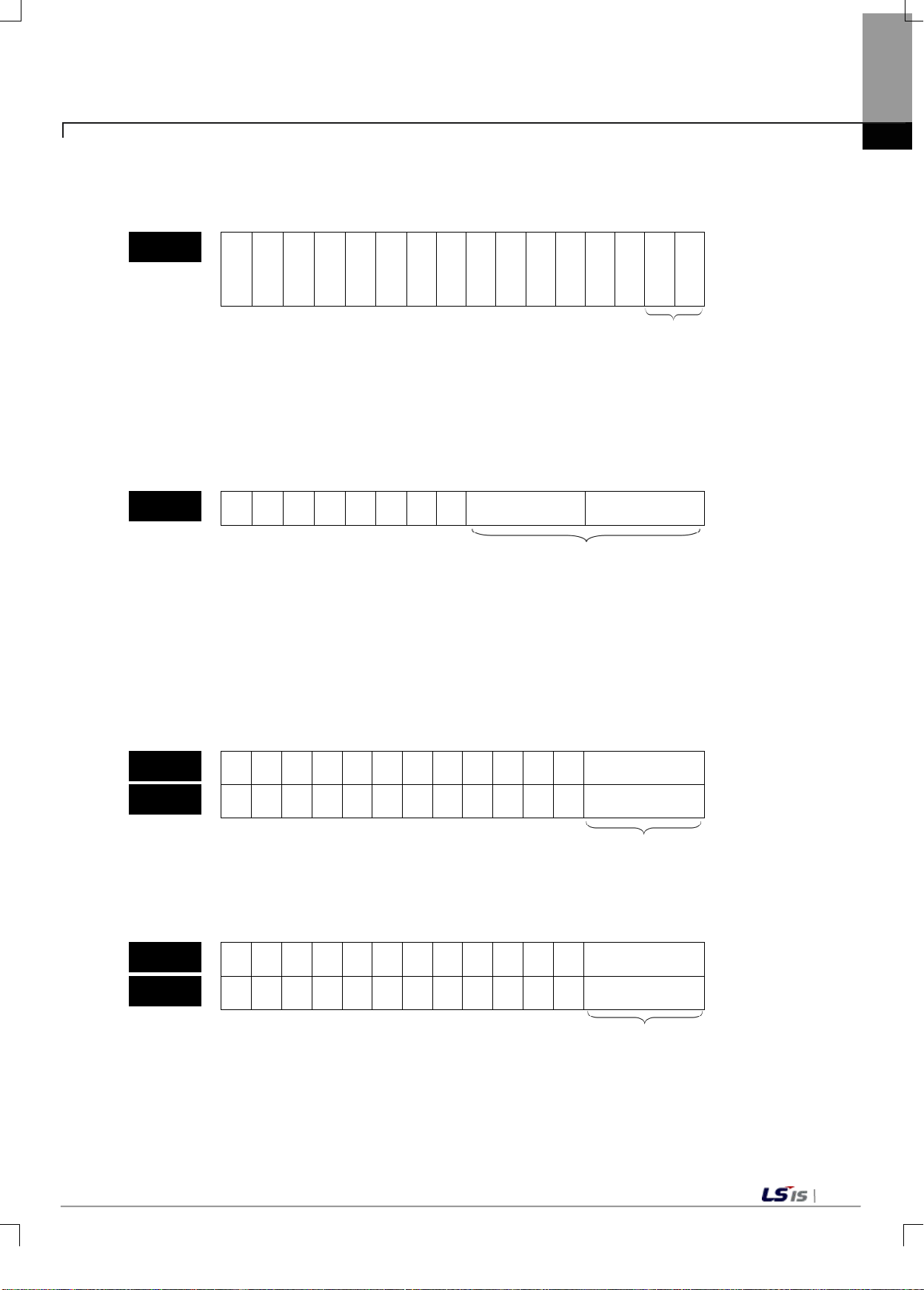
1) Operating channel
(1) The entire channel is in stop when the operating channel is not set.
15
14
13
12
11
10
C
h
1
0
C
h
0
Stop : 0(bit)
Running: 1(bit)
2) Weigh mode
(1) Weigh mode is divided into a total of five categories, including simple weighing(0), supply(simple
comparison)(1),supply(sequence comparison)(2), discharge(simple comparison)(3), and discharge
(sequence comparison)(4).
(2) When weigh mode is not set, it is set to simple weighing (0).
15
14
13
12
11
10
Channel1 Channel 0
0
Simple weighing : 0
Supply (simple comparison) : 1
Supply (sequence comparison) : 2
Discharge (simple comparison) : 3
Discharge (sequence comparison): 4
3) Free fall compensation cycle
(1) Free fall compensation cycle can be set from 0 to 9, and 0 will not execute the free fall compensation.
(2) When free fall compensation cycle value is not set, it is set to 0.
15
14
13
12
11
10
0
Channel0
Channel 1
4) Free fall compensation coefficient
(1) Free fall compensation coefficients can be set to 1(0), 1/4(1), 2/3(2), and 3/4(3).
15
14
13
12
11
10
Channel0
0
Channel1
1/4 : 1
2/4 : 2
3/4 : 3
4-7
Page 33
bit
bit
bit
bit
bit
bit
bit9 bit8 bit7 bit6 bit5 bit4 bit3 bit2 bit1 bit
bit
bit
bit
bit
bit
bit
bit9 bit8 bit7 bit6 bit5 bit4 bit3 bit2 bit1 bit
bit
bit
bit
bit
bit
bit
bit9 bit8 bit7 bit6 bit5 bit4 bit3 bit2 bit1 bit
Channel 0 (1 ~ 999)
Channel 1 (1 ~ 999)
bit
bit
bit
bit
bit
bit
bit9 bit8 bit7 bit6 bit5 bit4 bit3 bit2 bit1 bit
No. 10
No. 11
No. 13
No. 12
No. 9
No. 8
No. 6
No. 7
Chapter 4 Memory Structure (for XBC)
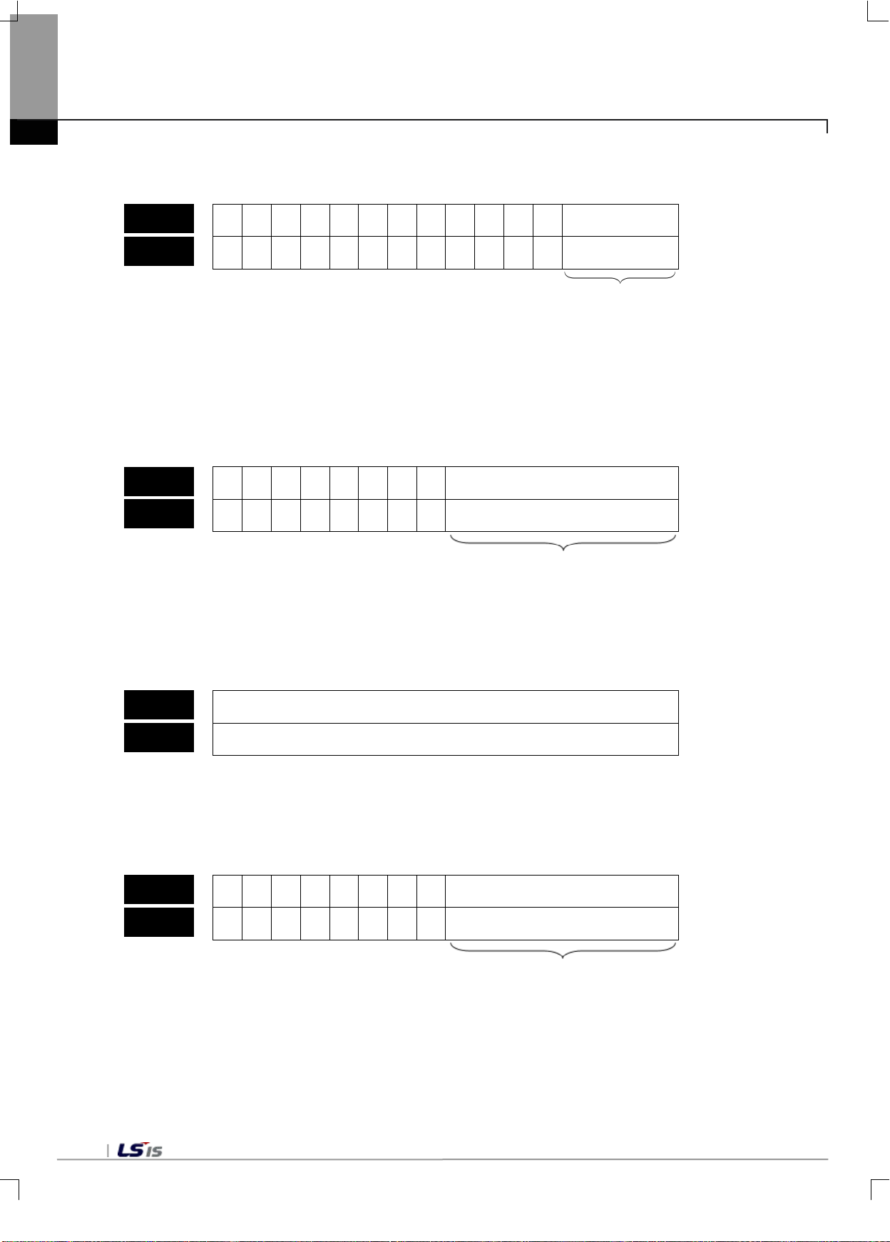
5) Average processing method
(1) Average processing methods can be set for each channel.
15
14
13
12
11
10
0
Channel 0
Channel 1
Moving average : 0
Moving/count average : 1
Moving /count average : 2
6) Moving average value
(1) The input range of the moving average value is from 3 to 9, and the actual range is 2^3 to 2^9.
(2) When the moving average value is not set, 5 is set.
15
14
13
12
11
10
0
Channel 0
Channel 1
Input range: 3 ~ 9
Actual range: 2^3 ~ 2^9
7) Count average value
(1) The input range of the count average value is from 1 to 999.
(2) When the count average value is not set, 10 is set.
15
14
13
12
11
10
0
8) Time average value
(1) The input range of the time average value is from 1 to 99, and setting unit is 100ms.
(2) When the time average value is not set, 1 is set.
15
14
13
12
11
10
Channel 0
0
4-8
Channel 1
Input range: 1 ~ 99 (100ms)
Page 34
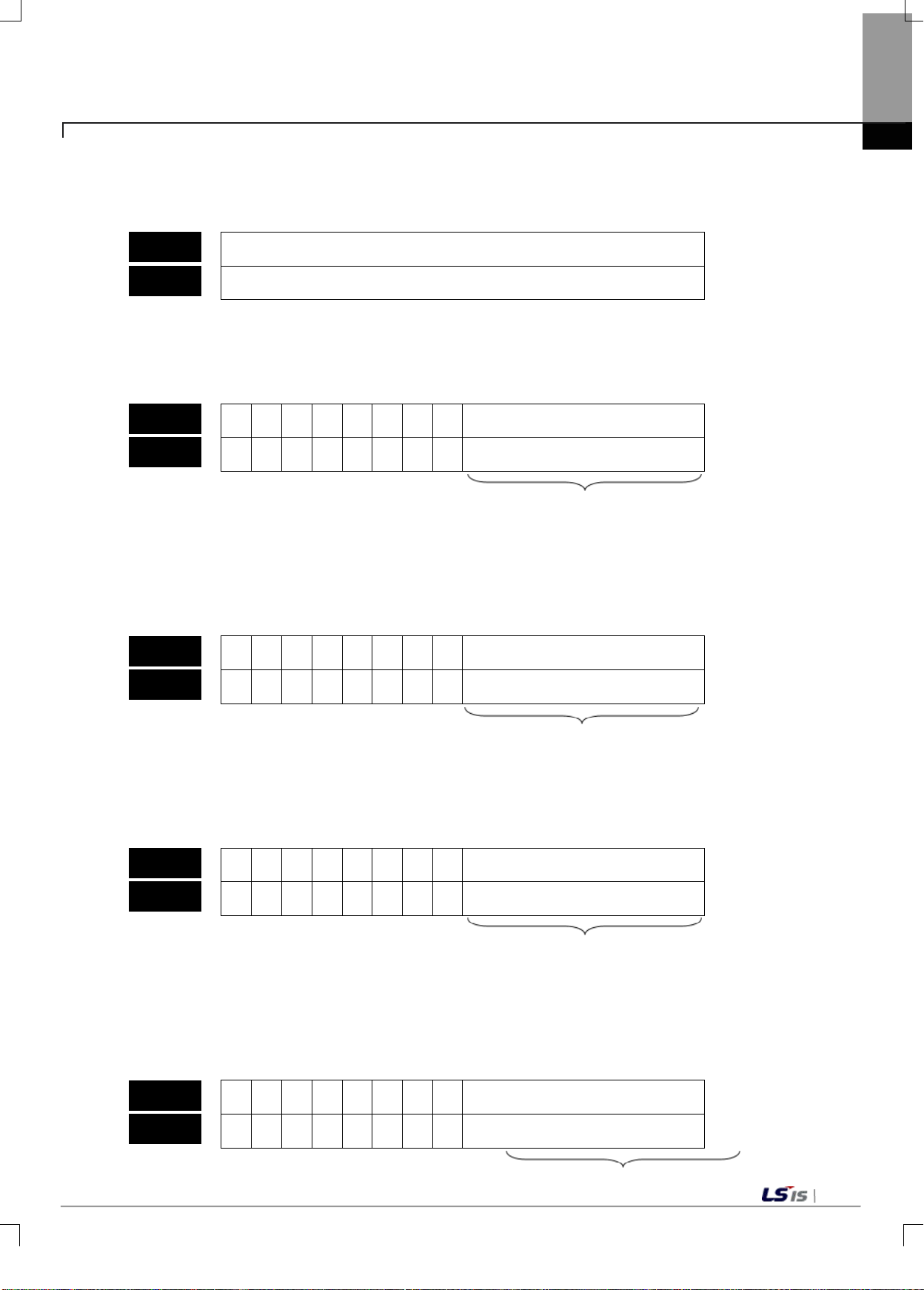
bit
bit
bit
bit
bit
bit
bit9 bit8 bit7 bit6 bit5 bit4 bit3 bit2 bit1 bit
bit
bit
bit
bit
bit
bit
bit9 bit8 bit7 bit6 bit5 bit4 bit3 bit2 bit1 bit
bit
bit
bit
bit
bit
bit
bit9 bit8 bit7 bit6 bit5 bit4 bit3 bit2 bit1 bit
bit
bit
bit
bit
bit
bit
bit9 bit8 bit7 bit6 bit5 bit4 bit3 bit2 bit1 bit
bit
bit
bit
bit
bit
bit
bit9 bit8 bit7 bit6 bit5 bit4 bit3 bit2 bit1 bit
No. 14
No. 15
No. 22
No. 23
No.20
No. 21
No. 18
No. 19
No. 16
No. 17
Chapter 4 Memory Structure(for XBC)
9) Stable determination range
(1) The input range of the stable determination range is from 0 to 999.
(2) When the stable determination range is not set, 5 is set.
15
14
13
12
11
10
0
Channel 0 (0 ~ 999)
Channel 1 (0 ~ 999)
10) Stable determination time
(1) The input range of the stable determination time is from 0 to 99, and setting unit is 100ms.
(2) When the stable determination range is not set, 10(1 sec) is set.
15
14
13
12
11
10
Channel 0
0
Channel 1
Input range: 0 ~ 99 (100ms)
11) Zero tracking range
(1) Zero tracking range is from 0,1 to 99.
(2) When zero tracking range is not set, it is set to 3.
15
14
13
12
11
10
0
Channel 0
Channel 1
Input range: 0, 1 ~ 99
12) Zero tracking time
(1) The input range of the zero tracking time is from 0 to 99, and setting unit is 100ms.
(2) When the zero tracking time is not set, it is set to 30.
15
14
13
12
11
10
Channel 0
0
Channel1
Input range : 0 ~ 99
13) Near zero range settings
(1) The input range of the near zero range settings is from 1 to 99, and setting range is %.
(2) When the near zero settings are not entered, it is set to 20.
15
14
13
12
11
10
Channel 0
Channel1
0
4-9
Page 35
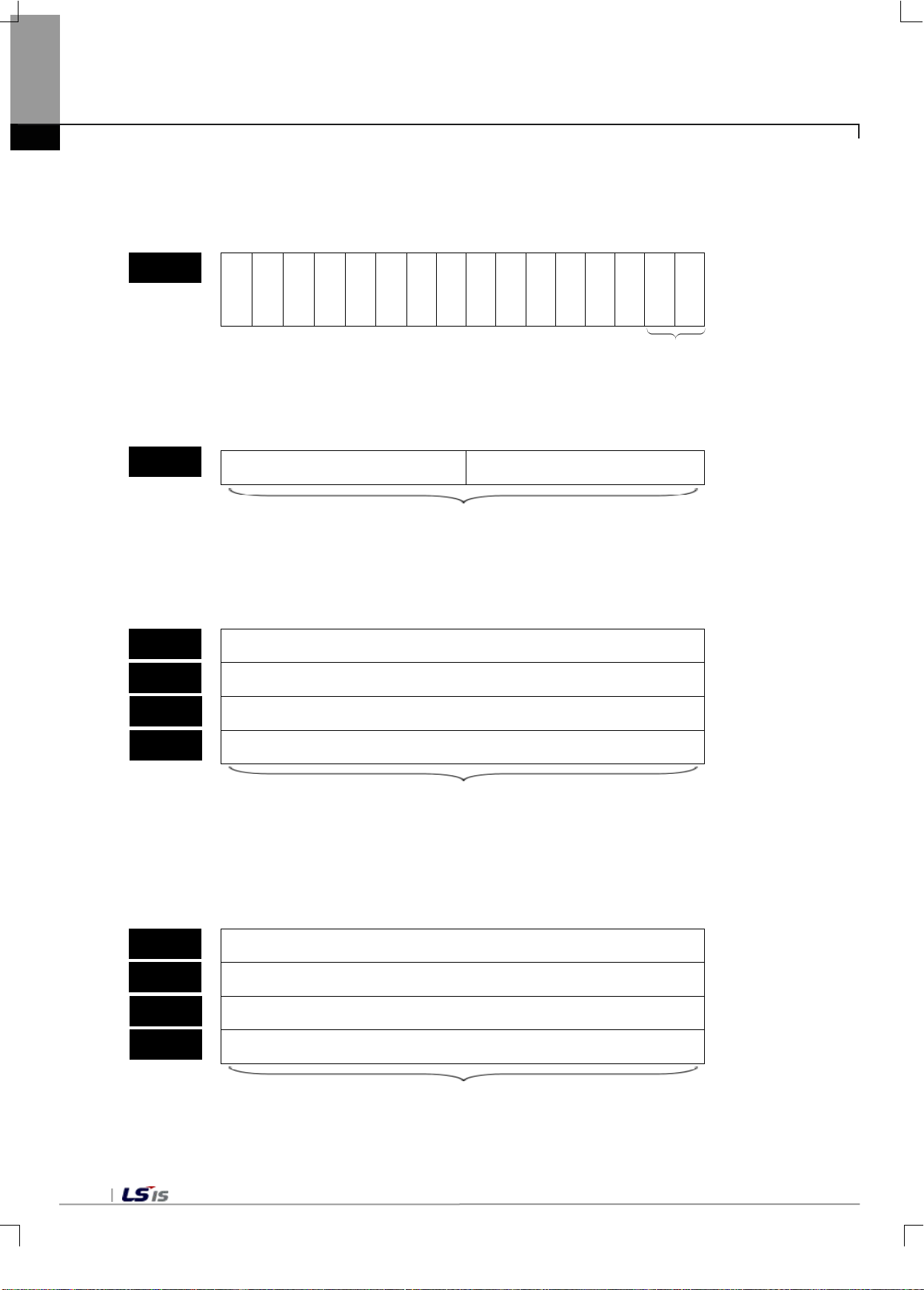
bit
bit
bit
bit
bit
bit
bit9 bit8 bit7 bit6 bit5 bit4 bit3 bit2 bit1 bit
Cha
Cha
bit
bit
bit
bit
bit
bit
bit9 bit8 bit7 bit6 bit5 bit4 bit3 bi
bit1 bit
bit
bit
bit
bit
bit
bit
bit9 bit8 bit7 bit6 bit5 bit4 bit3 bit2 bit1 bit
Channel 0(Upper)
bit
bit
bit
bit
bit
bit
bit9 bit8 bit7 bit6 bit5 bit4 bit3 bit2 bit1 bit
Channel 0(Lower)
No. 24
No. 26
No. 27
No. 34
No. 35
No. 28
No. 29
No. 36
No. 37
No. 25
Chapter 4 Memory Structure (for XBC)
Input range: 1 ~ 99
14) Sequence information
(1) It displays the setting to enable/disable alarm functions.
15
14
13
12
11
10
nne
l 1
0
nne
l 0
15) Near zero
(1) The setting range of near zero is from 0 to 99.
(2) When near zero is not set, it is set to 0.
15
14
13
12
11
10
Channel 0 Channel 1
Input range: 0 ~ 99
16) Gross weight LL
(1) The setting range of gross weight LL is from 0 to 999999.
(2) When gross weight LL is not set, it is set to 0.
15
14
13
12
11
10
Channel 0(Lower)
Channel 1(Lower)
Channel 1(Upper)
t2
0
0
4-10
Input range: 0 ~ 999999
17) Gross weight H
(1) The setting range of gross weight H is from gross weight L to gross weight HH.
(2) When gross weight H is not set, it is set to 0.
15
14
13
12
11
10
Channel 0(Upper)
Channel 1(Lower)
Channel 1(Upper)
Input range: Gross weight L – gross weight HH
0
Page 36
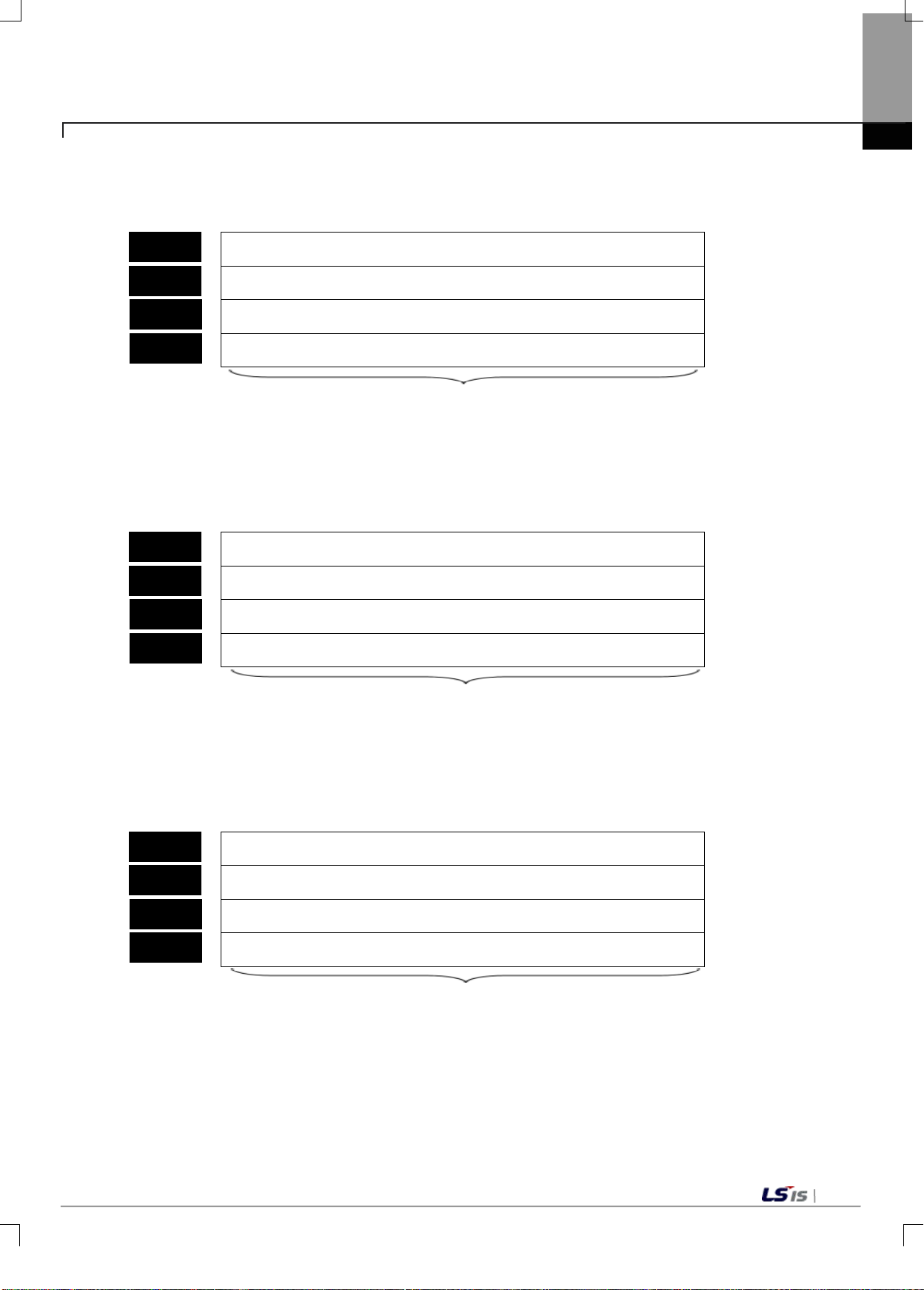
bit
bit
bit
bit
bit
bit
bit9 bit8 bit7 bit6 bit5 bit4 bit3 bit2 bit1 bit
bit
bit
bit
bit
bit
bit
bit9 bit8 bi
bit6 bit5 bit4 bit3 bit2 bit1 bit
Channel 0(Lower)
bit
bit
bit
bit
bit
bit
bit9 bit8 bit7 bit6 bit5 bit4 bit3 bit2 bit1 bit
Channel 0(Lower)
Channel 0(Upper)
No. 30
No. 31
No. 38
No. 39
No. 32
No. 33
No. 40
No. 41
No. 42
No. 43
No. 52
No. 53
Chapter 4 Memory Structure(for XBC)
18) Gross weight L
(1) The setting range of gross weight L is from gross weight LL to gross weight H.
(2) When gross weight Lo is not set, it is set to 0.
15
14
13
12
11
10
0
Channel 0(Lower)
Channel 0(Upper)
Channel 1(Lower)
Channel 1(Upper)
Input range: Gross weight L – gross weight H
19) Gross weight LL
(1) The setting range of gross weight LL is from 0 to gross weight L.
(2) When gross weight LL is not set, it is set to 0.
15
14
13
12
11
10
t7
0
Channel 0(Upper)
Channel 1(Lower)
Channel 1(Upper)
Input range: 0 – gross weight L
20) Final set gross weight
(1) The setting range of final set gross weight is from 0 to 999999.
(2) When final set gross weight is not set, it is set to 0.
15
14
13
12
11
10
Channel 1(Lower)
Channel 1(Upper)
999999
0
Input range : 0 -
4-11
Page 37
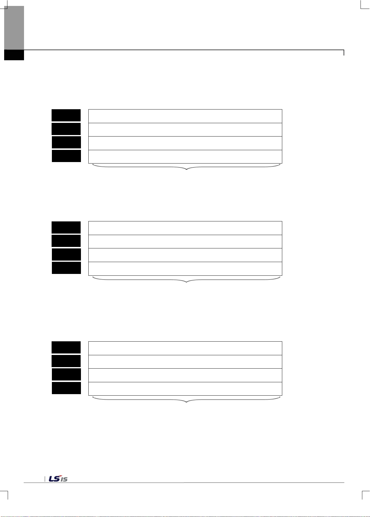
bit
bit
bit
bit
bit
bit
bit9 bit8 bit7 bit6 bit5 bit4 bit3 bit2 bit1 bit
Channel 0(Lower)
bit
bit
bit
bit
bit
bit
bit9 bit8 bit7 bit6 bit5 bit4 bit3 bit2 bit1 bit
bit
bit
bit
bit
bit
bit
bit9 bit8 bit7 bit6 bit5 bit4 bit3 bit2 bit1 bit
Channel 0(Lower)
No. 44
No. 45
No. 54
No. 55
No. 46
No. 47
No. 56
No. 57
No. 48
No. 49
No. 58
No. 59
Chapter 4 Memory Structure (for XBC)
21) Step 1 gross weight
(1) The setting range of step 1 gross weight is from 0 to 999999
(2) When step 1 gross weight is not set, it is set to 0.
15
14
13
12
11
10
0
Channel 0 (Upper)
Channel 1(Lower)
Channel 1(Upper)
Input range: 0 ~ 999999
22) Step 2 gross weight
(1) The setting range of step 2 gross weight is from 0 to 999999.
(2) When step 2 gross weight is not set, it is set to 0.
15
14
13
12
11
10
Channel 0(Lower)
0
Channel 0(Upper)
Channel 1(Lower)
Channel 1(Upper)
Input range: 0- 999999
23) Free fall weight
(1) The setting range of free fall gross weight is from 0 to 999999.
(2) When free fall weight is not set, it is set to 0.
15
14
13
12
11
10
Channel 0(Upper)
Channel 1(Lower)
Channel 1(Upper)
Input range: 0 - 999999
0
4-12
Page 38
bit
bit
bit
bit
bit
bit
bit9 bit8 bit7 bit6 bit5 bit4 bit3 bit2 bit1 bit
Channel 0
Channel 1
bit
bit
bit
bit
bit
bit
bit9 bit8 bit7 bit6 bit5 bit4 bit3 bit2 bit1 bit
Channel 1
bit
bit
bit
bit
bit
bit
bit9 bit8 bit7 bit6 bit5 bit4 bit3 bit2 bit1 bit
bit
bit
bit
bit
bit
bit
bit9 bit8 bit7 bit6 bit5 bit4 bit3 bit2 bit1 bit
Channel 0(Lower)
Channel 0(Upper)
No. 50
No. 60
No. 51
No. 61
No. 62
No. 63
No. 70
No. 71
No. 64
No. 65
No. 72
No. 73
Chapter 4 Memory Structure(for XBC)
24) Weight lack value
(1) The setting range of weight lack value is from 0 to 9999.
(2) When weight lack value is not set, it is set to 0.
15
14
13
12
11
10
0
Input range: 0 - 9999
25) Weight over value
(1) The setting range of weight lack value is from 0 to 9999.
(2) When weight lack value is not set, it is set to 0.
15
14
13
12
11
10
Channel 0
0
Input value: 0 - 9999
26) Load cell maximum weight
(1) The setting range of load cell maximum weight is from 0 to 999999.
(2) When load cell maximum weight is not set, it is set to 0.
15
14
13
12
11
10
0
Channel 0(Lower)
Channel 0(Upper)
Channel 1(Lower)
Channel 1(Upper)
Input range: 0 - 999999
27) Load cell standard weight
(1) The setting range of standard weight is from 0 to load cell standard weight.
(2) When standard weight is not set, it is set to 0.
15
14
13
12
11
10
0
Channel 1(Lower)
Channel 1(Upper)
Input range: 0 – load cell standard weight
4-13
Page 39
bit
bit
bit
bit
bit
bit
bit9 bit8 bit7 bit6 bit5 bit4 bit3 bit2 bit1 bit
bit
bit
bit
bit
bit
bit
bit9 bit8 bit7 bit6 bit5 bit4 bit3 bit2 bit1 bit
Channel 0
bit
bit
bit
bit
bit
bit
bit9 bit8 bit7 bit6 bit5 bit4 bit3 bit2 bit1 bit
No. 68
No. 76
No. 66
No. 74
No. 67
No. 75
No. 78
Chapter 4 Memory Structure (for XBC)
28) Calibration parameters
(1) Unit specification
The measuring unit of load cell input module can be divided into t, kg, g.
The measuring unit of load cell input module is set to kg as a default value..
15
14
13
12
11
10
Channel 0
Channel 1
kg : 0x6B67
g
: 0x0067
t :
0x0074
(2) Scale specification
The scale unit of load cell input module can be set to 1, 2, 5 and 10.
When the scale unit is not specified, it is set to 1.
0
Channel 0
Channel 1
1 : 0
2 : 1
5 : 2
10
: 4
(3) Decimal point
The decimal point of load cell input module can be set to 1, 0.1, 0.01, and 0.001.
When the decimal point is not specified, it is set to 1.
15
14
13
12
11
10
0
Channel 1
29) Error code
(1) Error information can be confirmed if the module is in error status.
15
14
13
12
11
10
0
Error code(refer to fault diagnosis in Chapter 9)
4-14
Page 40
S2 O - O - - - - - - O O O O O
module is stored
F0015
F0016
F 0
1
.
.
.
F0022
1번 BASE의 SLOT 4번에
특수모듈이 없거나 PUT명령
수행을 정상적으로 완료 못했을
경우
COMMAND
PUT
는 PUT를 나타냄
COMMAND
P
sl
PUTP
sl S2
N
S1
S2
NS1
If there is no Load cell mo dule in
not normally completed
_____ represents PUT
Chapter 4 Memory Structure(for XBC)
4.2.2 Methods on how to use PUT/GET commands
1) PUT command
Available areas
Command
PUT(P)
PMK F L T C S Z D.x R.x
sl - - - - - - - - - O - - - -
S1 - - - - - - - - - O - - - -
N O - O - - - - - - O - - - -
Con
stant U N D R
Step
Error
(F110)
4~7 - - -
[Area setting]
Operand Description Data size
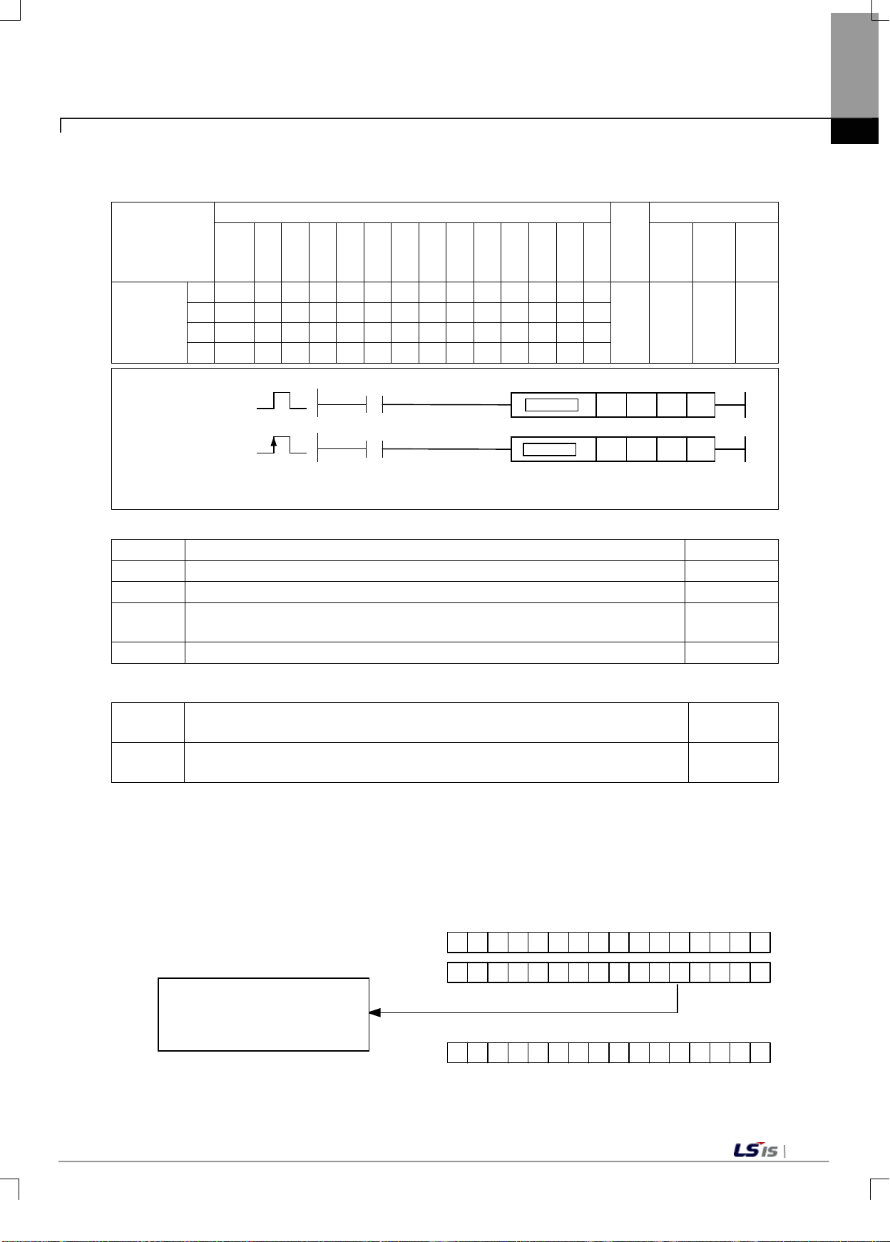
sl The number of a slot equipped with a Load Cell module(set to hexadecimal) WORD
S1 The address of internal memory of Load Cell WORD
S2
Start number or constant of the device in which data to be stored in the Load Cell
Flag
Zero
(F111)
WORD
Carry(
F112)
N The number of data to be stored WORD
[Flag set]
Flag Content
PUT/GET
error
(1) This command is used in case where data is to be written in a Load Cell module that has a memory.
(2) Wor d data is written as m uch as N from the devic e specified as S2 in the special m emory (designated as
S1) specified as sl(slot number of the Load Cell module).
(3) If there is no Load Ce ll m odule in the position specified as sl(slot number of the Load Cel l m odule), or P UT
command is not normally executed, the corresponding position bit of F0015~F0022(WORD), which is
PUT/GET error Flag, is set.
No. 4 slot of No. 1 base, or the
execution of PUT command is
- If there is no Load Cell module in the specified slot.
- If PUT/GET commands cannot be properly ex ecuted.
Device
number
F0015 ~
F0022
4-15
Page 41
M00021
PUT h14 2 D00100 4
M00000
PUT h07 10 D1000 40
M00000
PUT h03 5 M00010 3
번지
M00010
M00011
M00012
10
20
30
10
20
30
5
6
7
<CPU의 M영역> <특수모듈의 공용RAM>
<M area of CPU>
< Common RAM of Load cell module>
Address
Chapter 4 Memory Structure (for XBC)
(4) As for t he settin g metho d of sl(slot number of the Load Cell m odule), two-di git hex adecim al number is set.
As in the program below, in the case of h14, the first number ’1’ represents the base number, and the
second ‘4’ is the slot number.
2) Example of using PUT command
(1) If input signal M00000 is On, the program writes the cont ents of 40 words of D100 0-D1039 in the memor y
No. 10 to No. 49 of the Load Cell module mounted on the slot number 7 of number 0 base
(2) The progr am that wr ites the d ata of 3 words of M00010-M00012 in the mem ory No. 5 to N o. 7 of the Load
Cell module mounted on the slot number 3 of number 0 base
4-16
Page 42
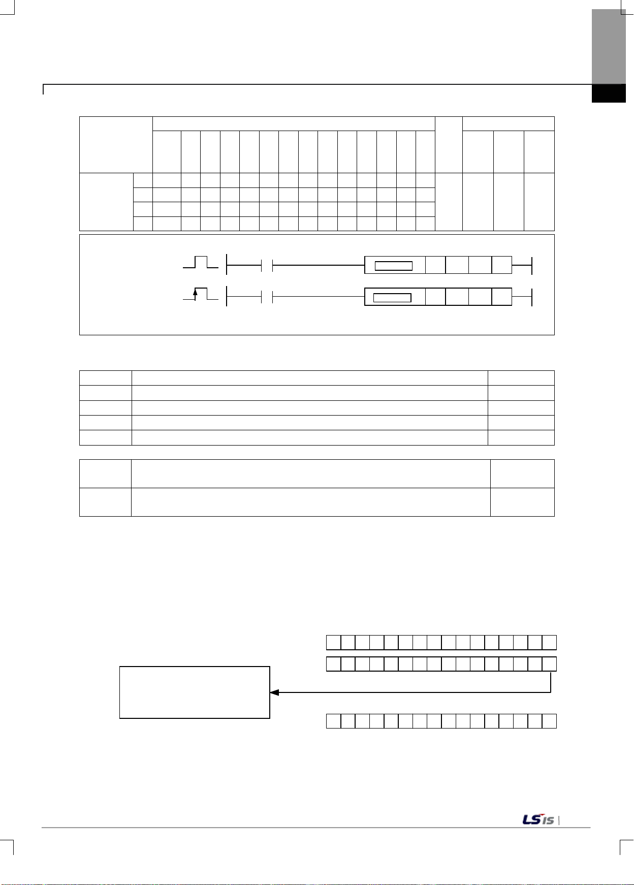
t
sl - - - - - - - - - O - - - -
F0015
F0016
F 0
1
.
.
.
F0022
1번 BASE의 SLOT 0번에
특수모듈이 없거나 GET명령
수행을 정상적으로 완료 못했을
경우
COMMAND
GET
는 GET를 나타냄
COMMAND
P sl
GETP
D NS
sl D NS
_____ represents PUT
If there is no Load cell module in
not normally completed
3) GET command
Command령
Available areas
PMK F L T C S Z D.x R.x
Chapter 4 Memory Structure(for XBC)
Flag
Con
stan
U N D R
Step
Error
(F110)
Zero
(F111)
Carry
(F112)
GET(P)
S - - - - - - - - - O - - - D O - O - - - - - - - O O O O
N O - O - - - - - - O O O O O
4~7 - - -
[Area setting]
Operand Description Data size
sl The number of a slot equipment with a Load Cell module(set to hexadecimal) WORD
S Start number of internal memory of Load Cell module WORD
D Start number of the device in CPU in which data to be read is to be stored WORD
N The number of data to be read WORD
[Flag set)]
Flag Content
PUT/GET
error
- if there is no Load Cell module in the specified slot.
- If PUT/GET commands cannot be properly ex ecuted.
Device
number
F0015 ~
F0022
(1) This command is used in case where data of the Load Cell module that has a memory needs to be read.
(2) N word data is stored in the internal device area specified as D from the memory (designated as S:
address) of the Load Cell module specified as sl(slot number of the Load Cell module).
(3) If there is no Lo ad Cell m odule in the position specified as sl(slot number of the Load C ell module), or GET
command is not normally executed, the corresponding position bit of F0015~F0022(WORD), which is
PUT/GET error Flag, is set.
No. 0 slot of No. 1 base, or the
execution of GET command is
4-17
Page 43
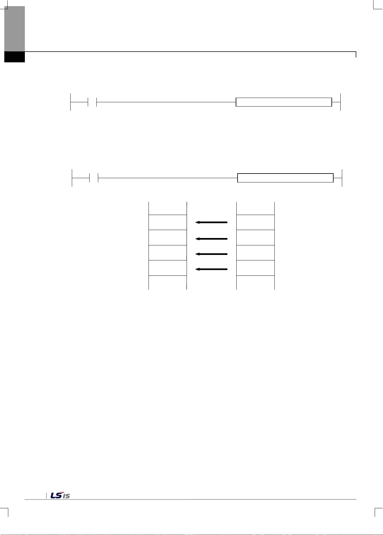
M00021
GET h10 100 D00100 4
P00001
GET h03 0 D00010 4
번지
D00010
D00011
D00012
100
120
130
100
120
130
0
1
2
<CPU의 M영역>
<특수모듈 고정영역>
190 190
3
D00013
< Common RAM of Load cell module>
<M area of CPU>
Address
Chapter 4 Memory Structure (for XBC)
(4) As for th e settin g metho d of sl(slot number of the Load C ell m odule), two-di git hex adecim al number is set.
As in the program belo w, in the case of ‘h10’, the f irst num ber ’1’ represe nts the bas e num ber, and the second
‘0’ is the slot number.
4) Example of using GET command
(a) If input signal P00001 is On, the data of 4 words from the internal m emory No. 0 of the Loa d Cell module
mounted on the slot number 3 of number 0 base in D00010 to D00013.
4-18
Page 44
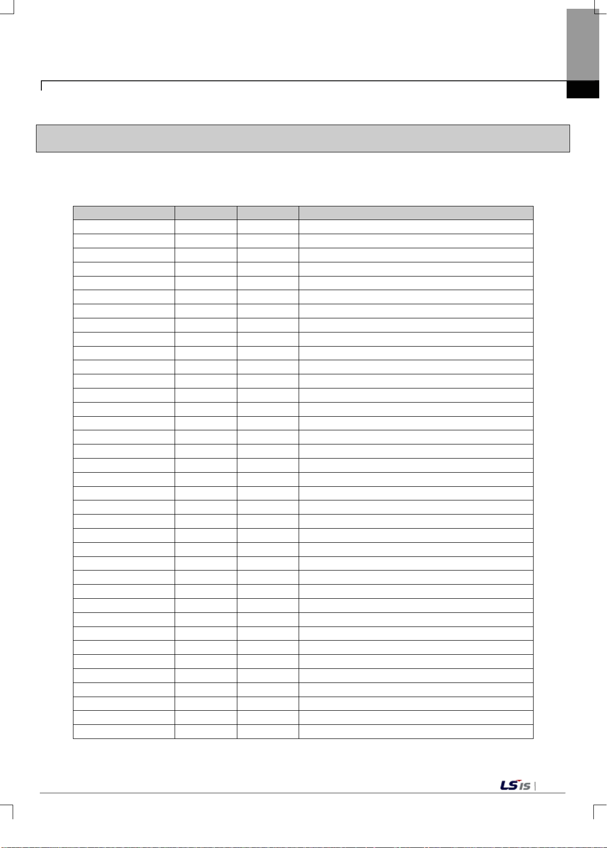
Global variables
Data type
Memory
Description
point calibration mode
Chapter 5 Memory Structure(for XEC)
5.1 G lobal variables(Data area)
5.1.1 Global variables(Data area)
U device area of the load cell input module is shown in Table 5.1.
_01_CH0_GWMIN DWORD %UD0.1.10
_01_CH1_GWMAX DWORD %UD0.1.11 Load cell input module: channel1 gross weight maximum value
_01_CH1_GWMIN DWORD %UD0.1.12 Load cell input module: channel1 gross weight minimum value
_01_CH0_GWDATA DINT %UD0.1.3 Load cel l input module: channel0 gross weight value
_01_CH1_GWDATA DINT %UD0.1.4 Load cel l input module: channel1 gross weight value
_01_CH0_ADDATA DWORD %UD0.1.5 Load cell input module: channel0 tare weight value
_01_CH1_ADDATA DWORD %UD0.1.6 Load cell input module: channel1 tare weight value
_01_CH0_NETDATA DINT %UD0.1.7 Load cell input module: channel0 net weight value
_01_CH1_NETDATA DINT %UD0.1.8 Load cell input module: channel1 net weight value
_01_CH0_GWMAX DWORD %UD0.1.9 Load cell input module: channel0 gross weight maximum value
_01_CH0_CUR_FFVAL WORD %UW0.1.26 Load cell input module: channel0 current free fall value
_01_CH1_CUR_FFVAL WORD %UW0.1.27 Load cell input module: channel1 current free fall value
_01_ECODE WORD %UW0.1.28 Load cell input module: error code
_01_ERR BOOL %UX0.1.0 Load cell input module: module error
_01_RDY BOOL %UX0.1.15 Load cell input module: module Ready
_01_CH0_RUN BOOL %UX0.1.16 Load cell input module: channel0 running
_01_CH1_RUN BOOL %UX0.1.17 Load cell input module: channel1 running
_01_CH0_CALMOD BOOL %UX0.1.24 Load cell input module: channel0 calibration mode
_01_CH1_CALMOD BOOL %UX0.1.25 Load cell input module: channel1 calibration mode
_01_CH0_ERR BOOL %UX0.1.30 Load cel l input module: channel0 error
_01_CH1_ERR BOOL %UX0.1.31 Load cel l input module: channel1 error
_01_CH0_STBL BOOL %UX0.1.32 Load cel l input module: channel0 stable status
_01_CH1_STBL BOOL %UX0.1.33 Load cel l input module: channel1 stable statue
_01_CH0_ZERO BOOL %UX0.1.34 Load cell input module: channel0 ZERO status
_01_CH1_ZERO BOOL %UX0.1.35 Load cell input module: channel1 ZERO statue
_01_CH0_COMPLETE BOOL %UX0.1.36 Load cell input module: channel0 weighing complete status
_01_CH1_COMPLETE BOOL %UX0.1.37 Load cell input module: channel1 weighing complete status
_01_CH0_SP1 BOOL %UX0.1.38 Load cell input module: channel0 step 1 status
_01_CH0_SP2 BOOL %UX0.1.39 Load cell input module: channel0 step 2 status
_01_CH0_SP3 BOOL %UX0.1.40 Load cell input module: channel0 step 3 status
_01_CH0_UNDER BOOL %UX0.1.41 Load cell input module: channel0 lack status
_01_CH0_OVER BOOL %UX0.1.42 Load cell input module: channel0 over status
_01_CH1_SP1 BOOL %UX0.1.43 Load cell input module: channel1 step 1 status
_01_CH1_SP2 BOOL %UX0.1.44 Load cell input module: channel1 step 2 status
_01_CH1_SP3 BOOL %UX0.1.45 Load cell input module: channel1 step 3 status
_01_CH1_UNDER BOOL %UX0.1.46 Load cell input module: channel1 lack status
_01_CH0_CAL1REQ BOOL %UX0.1.464
Chapter 5 Memory Structure(for XEC)
Load cell input module: channel0 gross weight minimum value
Load cell input module: channel0 1-
5-1
Page 45
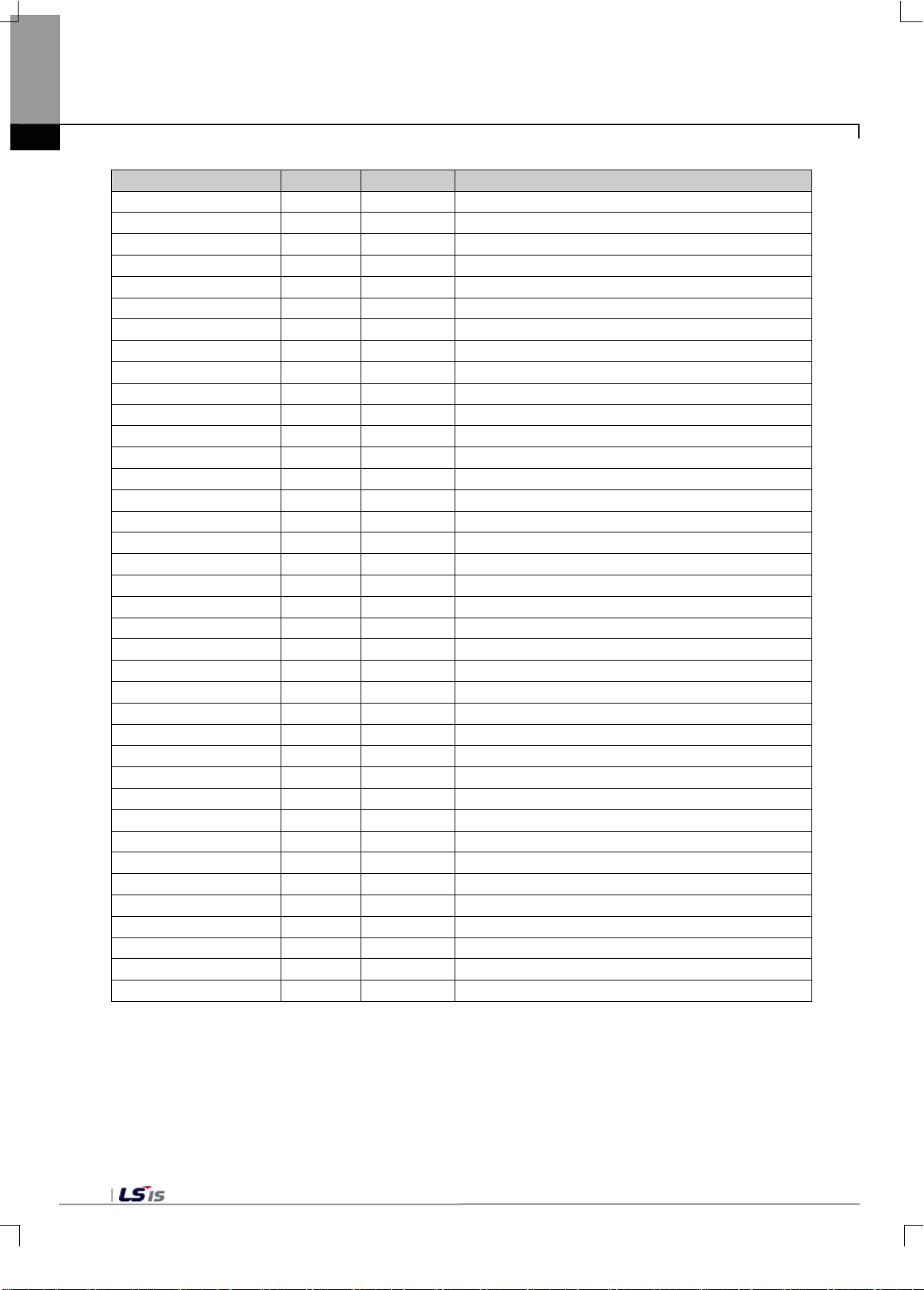
Global variables
Data type
Memory
Description
point calibration mode
point calibration mode
calibration value storage
calibration value storage
Chapter 5 Memory Structure (for XEC)
5-2
_01_CH1_CAL1REQ BOOL %UX0.1.465
_01_CH0_CAL2REQ BOOL %UX0.1.466
_01_CH1_CAL2REQ BOOL %UX0.1.467
_01_CH1_OVER BOOL %UX0.1.47 Load cell input module: channel1 over status
_01_CH0_ZCALEND BOOL %UX0.1.48 Load cell input module: channel0 zero calibration complete
_01_CH0_ZCALREQ BOOL %UX0.1.480 Load cell input module: channel0 zero calibrati on request
_01_CH1_ZCALREQ BOOL %UX0.1.481 Load cell input module: channel1 zero calibrati on request
_01_CH0_SCALREQ BOOL %UX0.1.482 Load cell input module: channel0 span calibration request
_01_CH1_SCALREQ BOOL %UX0.1.483 Load cell input module: channel1 span calibration request
_01_CH0_CALSTORE BOOL %UX0.1.484
_01_CH1_CALSTORE BOOL %UX0.1.485
_01_CH1_ZCALEND BOOL %UX0.1.49 Load cell input module: channel1 zero calibration complete
_01_CH0_ZSETREQ BOOL %UX0.1.496 Load cell input module: channel0 zero setting reques t
_01_CH1_ZSETREQ BOOL %UX0.1.497 Load cell input module: channel1 zero setting reques t
_01_CH0_ZRSTREQ BOOL %UX0.1.498 Load cell input module: channel0 zero reset request
_01_CH1_ZRSTREQ BOOL %UX0.1.499 Load cell input module: channel1 zero reset request
_01_CH0_SCALEND BOOL %UX0.1.50 Load cell input module: channel0 span calibration complete
_01_CH0_TAREREQ BOOL %UX0.1.500 Load cel l input module: channel0 tare setting
_01_CH1_TAREREQ BOOL %UX0.1.501 Load cel l input module: channel1 tare setting
_01_CH0_HOLDREQ BOOL %UX0.1.502 Load cel l input module: channel0 output hold request
_01_CH1_HOLDREQ BOOL %UX0.1.503 Load cel l input module: channel1 output hold request
_01_CH0_MAXMINREQ BOOL %UX0.1.504 Load cell input module: channel0 Minmax hold status
_01_CH1_MAXMINREQ BOOL %UX0.1.505 Load cell input module: channel1 Minmax hold status
_01_CH0_SEQREQ BOOL %UX0.1.506 Load cell input module: channel0 sequential control request
_01_CH1_SEQREQ BOOL %UX0.1.507 Load cell input module: channel1 sequential control request
_01_CH0_TARERSTREQ BOOL %UX0.1.508 Load cell input module: channel0 tare released command
_01_CH1_TARERSTREQ BOOL %UX0.1.509 Load cell input module: channel1 tare released command
_01_CH1_SCALEND BOOL %UX0.1.51 Load cell input module: channel1 span calibration complete
_01_CH0_CALEND BOOL %UX0.1.52 Load cell input module: channel0 calibration storage c omplet e
_01_CH1_CALEND BOOL %UX0.1.53 Load cell input module: channel1 calibration storage complete
_01_CH0_ZSET BOOL %UX0.1.64 Load cell input module: channel0 zero setting status
_01_CH1_ZSET BOOL %UX0.1.65 Load cell input module: channel1 zero setting status
_01_CH0_ZRST BOOL %UX0.1.66 Load cell input module: channel0 zero reset status
_01_CH1_ZRST BOOL %UX0.1.67 Load cell input module: channel1 zero reset status
_01_CH0_TSET BOOL %UX0.1.68 Load c el l input module: channel0 tare setting status
_01_CH1_TSET BOOL %UX0.1.69 Load c el l input module: channel1 tare setting status
_01_CH0_WEIGHTHLD BOOL %UX0.1.70 Load cell input module: channel0 output hold status
_01_CH1_WEIGHTHLD BOOL %UX0.1.71 Load cell input module: channel1 output hold status
Load cell input module: channel1 1-point calibration mode
Load cell input module: channel0 2Load cell input module: channel1 2-
Load cell input module: channel0
Load cell input module: channel1
Page 46
Global variables
Data type
Description
Chapter 5 Memory Structure(for XEC)
_01_CH0_MINMAXHLD BOOL %UX0.1.72 Load cell input module: channel0 Minmax hold status
_01_CH1_MINMAXHLD BOOL %UX0.1.73 Load cell input module: channel1 Minmax hold status
_01_CH0_NEARZERO BOOL %UX0.1.74 Load cell input module: channel0 near zero status
_01_CH1_NEARZERO BOOL %UX0.1.75 Load cell input module: channel1 near zero status
_01_CH0_GRSMINUS BOOL %UX0.1.76 Load cell input module: channel0 gross weight negative status
_01_CH1_GRSMINUS BOOL %UX0.1.77 Load cell input module: channel1 gross weight negative status
_01_CH0_NETMINUS BOOL %UX0.1.78 Load cell input module: channel0 net weight negative status
_01_CH1_NETMINUS BOOL %UX0.1.79 Load cell input module: channel1 net weight negative status
_01_CH0_HOOR BOOL %UX0.1.80 Load cell input module: channel0 high alarm occurrence
_01_CH1_HOOR BOOL %UX0.1.81 Load cell input module: channel1 high alarm occurrence
_01_CH0_LOOR BOOL %UX0.1.82 Load cel l input module: channel0 low alarm occurrence
_01_CH1_LOOR BOOL %UX0.1.83 Load cel l input module: channel1 low alarm occurrence
_01_CH0_HHOORSTAT BOOL %UX0.1.88 Load cell input module: channel0 high high status
_01_CH0_HOORSTAT BOOL %UX0.1.89 Load cell input module: channel0 high status
_01_CH0_LOORSTAT BOOL %UX0.1.90 Load cell input module: channel0 low status
_01_CH0_LLOORSTAT BOOL %UX0.1.91 Load cell input module: channel0 low l ow status
_01_CH1_HHOORSTAT BOOL %UX0.1.92 Load cell input module: channel1 high high status
_01_CH1_HOORSTAT BOOL %UX0.1.93 Load cell input module: channel1 high status
_01_CH1_LOORSTAT BOOL %UX0.1.94 Load cell input module: channel1 low status
_01_CH1_LLOORSTAT BOOL %UX0.1.95 Load cell input module: channel1 low l ow status
Memory
[Table 5. 1] U device area
- In device a lloc ation, xx repres ents the num ber of a base equ ipped with a m odule, and yy is th e num ber of
a slot equipped with a module.
5-3
Page 47
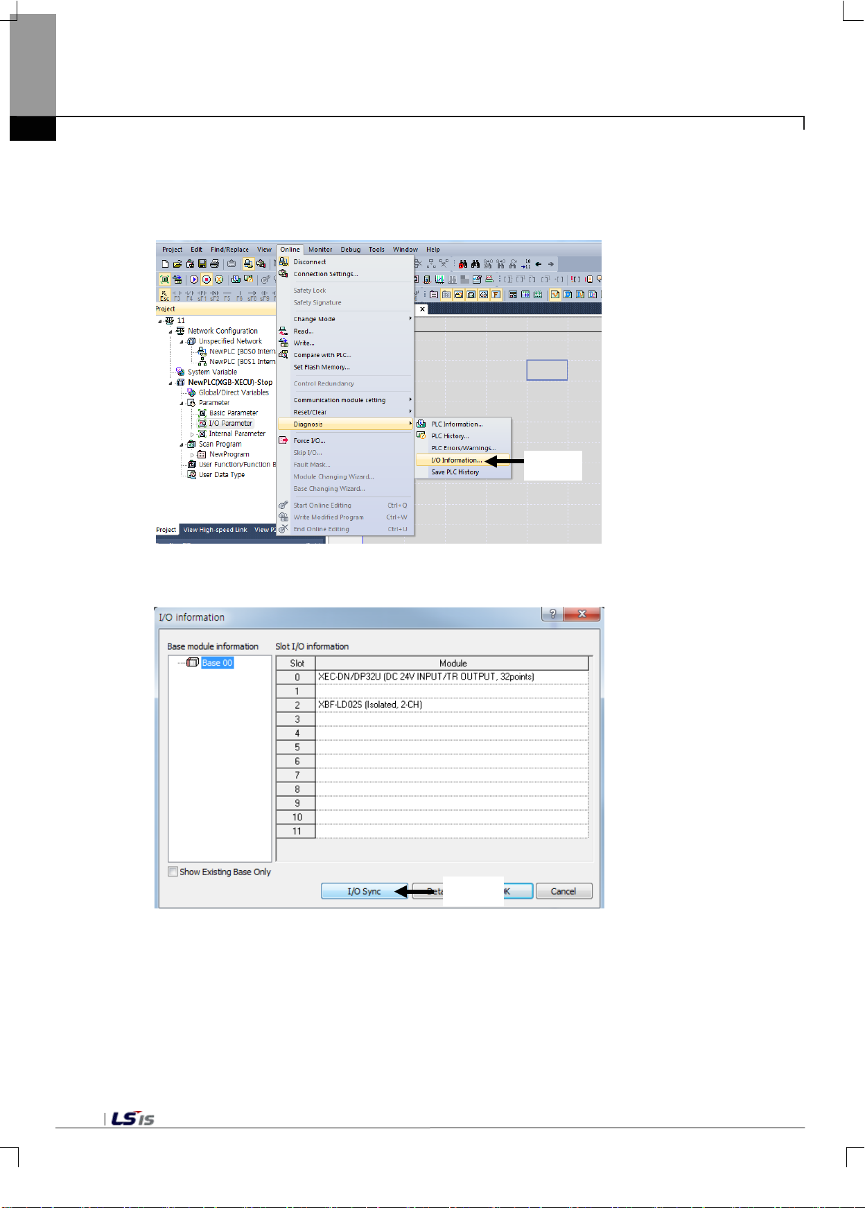
Click
Click
Chapter 5 Memory Structure (for XEC)
5.1.2 Me thods on how to use global variables
1) I/O synchronization
- Synchronize the I/O module you wish to use with XG5000.
(1) Click ‘Online - Diagnosis – I/O information’ in the main menu.
(2) Check the information of the load cell input module mounted in the I/O information win do w, and click I/O
synchronization.
5-4
Page 48
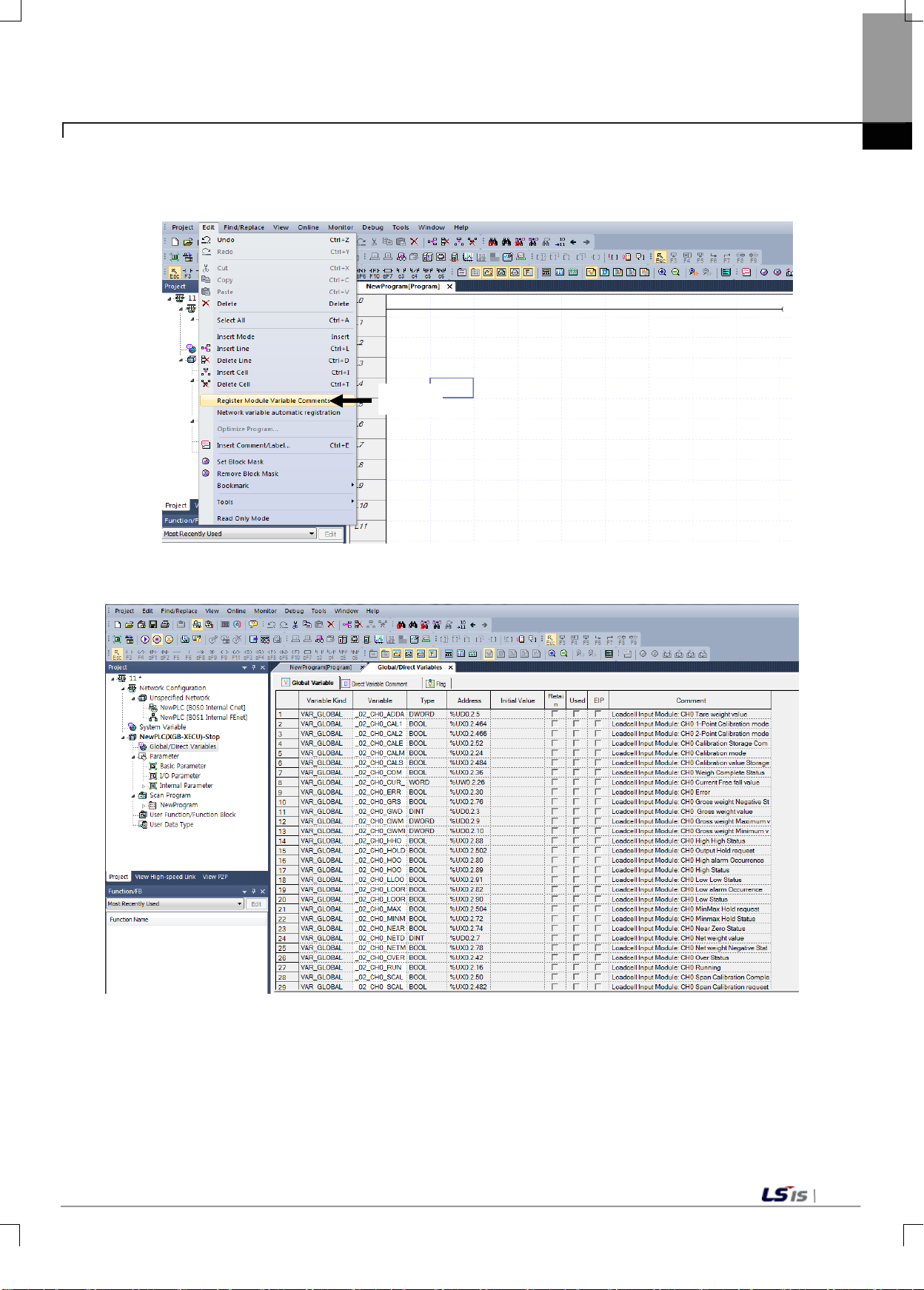
Click
Chapter 5 Memory Structure(for XEC)
2) Registration of g lob al var iables
- Register global variables of the module set in the I/O parameter.
(1) Select [special/communication module variable automatic registration] from the main menu [Edit].
(2) Check the registered variables by double-clicking the global/direc t var iab les of the projec t windo w.
5-5
Page 49
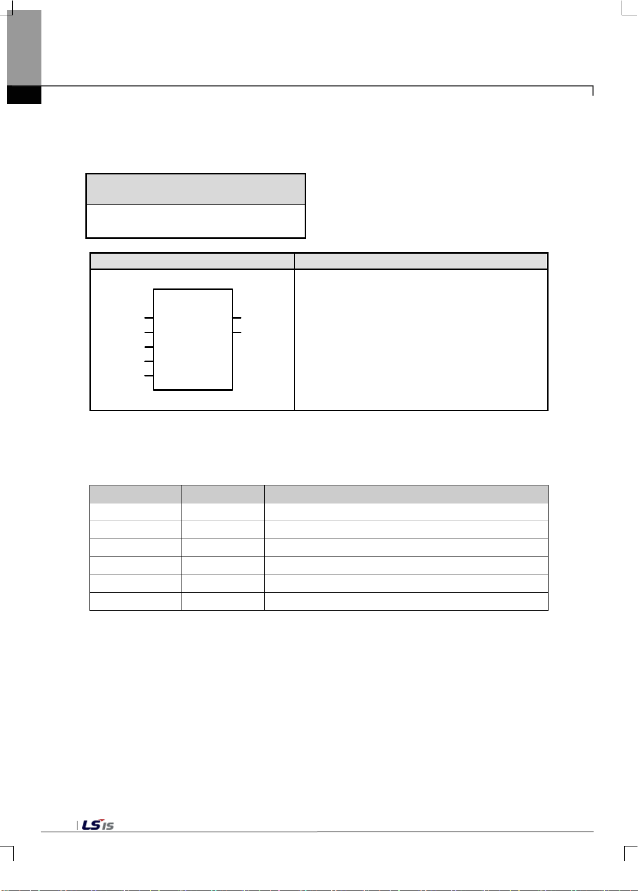
PUT
UINT
PUT
DONE
BASE
SLOT
MADDR
STAT
BOOL
USINT
UINT
USINT
*ANY
DATA
REQ
BOOL
Chapter 5 Memory Structure (for XEC)
5.1.3 PUT/GET function blocks
1) PUT function block
Write data in Load Cell module
Function block Description
Input REQ : Executes function in the case of 1
BASE : Fix the XGB ‘0’
SLOT : Specified slot position
MADDR : Module address
DATA : Data to be stored in the module
Output
* ANY: Among ANY types, WORD, DWORD, INT, USINT, DINT, and UDINT types are available
STAT : Error information
■ Functions
Read data from the specified Load Cell module.
Function block Input(ANY) type Description
DONE : 1 output when executed normally
5-6
PUT_WORD WORD S tore WORD data in the specified module address(MADDR)
PUT_DWORD DWORD S tore DWORD data in the specified module address(MADDR)
PUT_INT INT Store INT data in the specified module address(MADDR)
PUT_UINT UINT Store UNT data in the specified module address(MADDR)
PUT_DINT DINT Store DINT data in the specified module address(MADDR)
PUT_UDINT UDINT Store UDINT data in the specified module address(MADDR)
Page 50
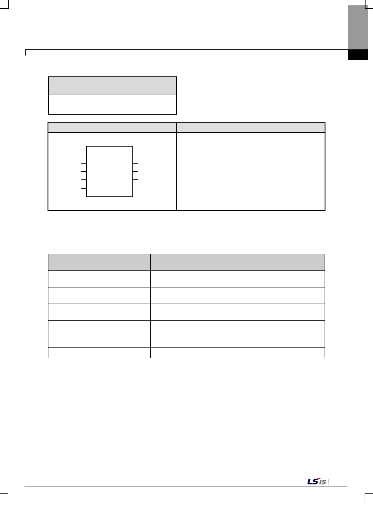
GET
Function block
Description
UINT
GET
DONE
BASE
SLOT
MADDR
STAT
BOOL
USINT
UINT
USINT
*ANY
DATA
REQ
BOOL
DATA : Data read from the module
2) GET function block
Read data from Load Cell module
Chapter 5 Memory Structure(for XEC)
Input REQ : Executes function in the case of 1
BASE : Fix the XGB ‘0’
SLOT : Specifies slot position
MADDR : module address
512(0x200) ~ 1023(0x3FF)
Output
*ANY: Among ANY types, WORD, DWORD, INT, UINT, DINT, and UDINT ty pes are availa bl e
STAT : Error information
DONE : 1 output when executed normally
■ Functions
Read data from the specified Load Cell module..
Function
block
GET_WORD WORD
GET_DWOR
D
GET_INT INT
GET_UINT UINT
GET_DINT DINT Read data as much as DINT from the specified module address
Output(ANY)type Description
Read data as much as WORD from the specified module
address(MADDR)
DWORD Read data as much as DWORD from the specified module address
Read data as much as INT from the specified module
address(MADDR)
Read data as much as UINT from the specified module
address(MADDR)
GET_UDINT UDINT Read data as much as UDINT from the specified module address
5-7
Page 51
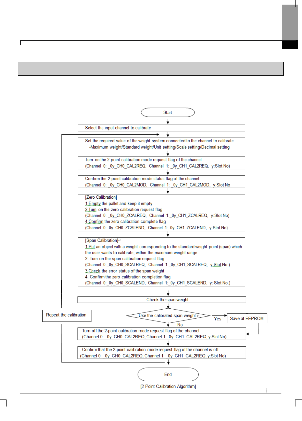
6-1
Chapter 6 Functions
6.1 Functions
6.1.1 Calibration Function
It performs calibration on the weight measurement range prior to measuring the actual gross weight.
1) 2-Point Calibration Algorithm
Chapter 6 Functions
Page 52
6-2
Chapter 6 Functions
Remark
(1) In case of measuring weight after calibration, start the measurement with the pallet empty (zero
point).
(2) For accurate m eas urement, the spa n wei ght ne eds to be no l ess tha n 10% of the m ax im um weight if
the resolution is less than 1/10000, or no less than 20% of the maximum weight if the res olution is
1/10000 or higher.When the span weig ht is les s than 10% of the maximum weight, a span calibrat io n
setting error occurs (error code 21#, where # is the channel number).
(3) The maximum resolution of XGB Load Cell input module is 40000.
If Maximum Weight / (dec imal*s cale) > 40000, a reso lution over error occ urs (er ror code 22#, where
# is the channel number).
(4) The XGB Load Ce ll input m odule support s 1㎷/V ~ 6 ㎷/V se nsitiv ity. Using a load c ell w ith sen sitiv ity
exceeding the said range will cause an internal resolution error (error code 23#, where # is the
channel number) or a zero point setting error (error code 20#, where # is the channel number).
Page 53
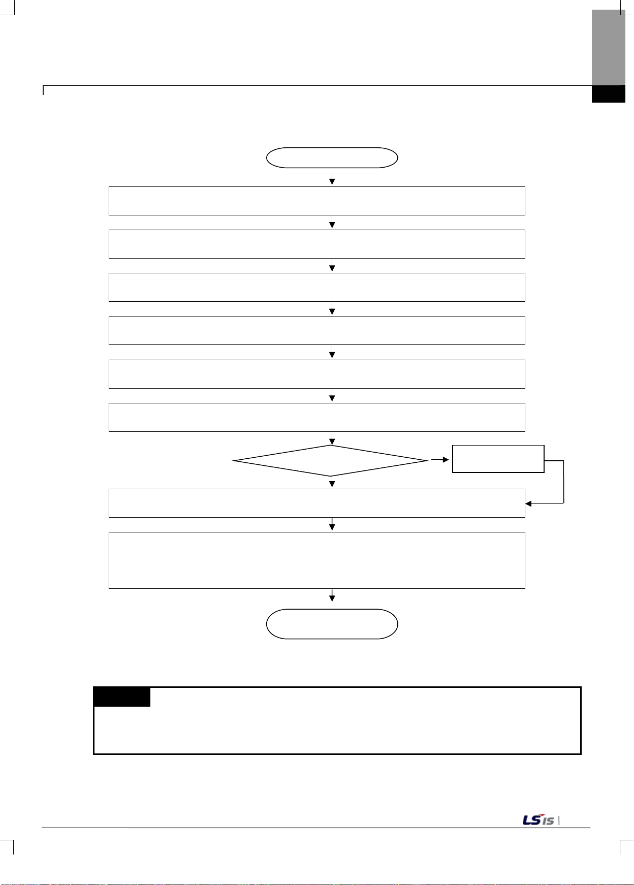
6-3
Perform this calibration if the weight value of the pallet is not 0 when empty.
Select the input channel to calibrate, and set the channel status to ‘Enable’.
Place a weight for zero calibration within the maximum weight range.
=> Confirm whether the current value is within the near zero range.
(Channel 0:_0y_CH0_CAL1REQ, Channel 1:_0y_CH1_CAL1REQ, y:Slot No)
Confirm the 1-point calibration mode status flag of the channel.
(Channel 0:_0y_CH0_CAL1MOD, Channel 1:_0y_CH1_CAL1MOD, y:Slot No
Turn on the zero calibration mode request flag of the channel.
(Channel 0: _0y_CH0_ZCALREQ, Channel 1:_0y_CH1_ZCALREQ, y:Slot No
(Channel 0: _0y_CH0_ZCALEND, Channel 1: _0y_CH1_ZCALEND, y:Slot No)
Turn offhe 1-point calibration mode request flag of the channel.
(Channel 0: _0y_CH0_CAL1REQ, Channel 1:_0y_CH1_CAL1REQ, y:Slot No)
(Channel 0: _0y_CH0_ZCALREQ, Channel 1: _0y_CH1_ZCALREQ, y:Slot No.
Start
End
not continue. In such case, perform 2-point calibration.
Yes.
No
2) 1-Point Calibration Algorithm
It only calibrates the zero point. It must be performed only after completing 2-point calibration.
Turn on the 1-point calibration mode request flag
Chapter 6 Functions
Confirm the zero calibration completion flag.
Use the calibrated zero weight.
Save at EEPROM
Confirm that the 1-point calibration mode request flag of the channel is off.
(Channel 0: _0y_CH0_CAL1REQ, Channel 1: _0y_CH1_CAL1REQ, y:Slot No.)
Confirm whether the zero calibration mode request flag of the channel is off.
[1-Point Calibration Algorithm]
Remark
(1) The 1-point calibration setting range is the near zero range.
(2) Near zero range is represented as % of the maximum weight.
(3) If a wiring status error occurs( error code 12#, wher e # is the channel n umber ), 1-point cali bration will
Page 54
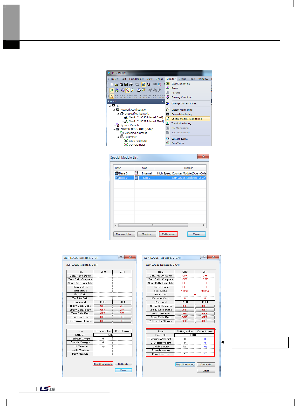
6-4
Chapter 6 Functions
3) Calibration on XG5000 Special Module Monitor Window (2-point calibration)
2-point calibration can be performed on the calibration window of the special module monitor.
Select the load cell input module from the special module list, then click 'Calibration.'
Click 'Start Monitoring' to Run calibration, then enter the calibration parts.
Enter calibration parts
Page 55
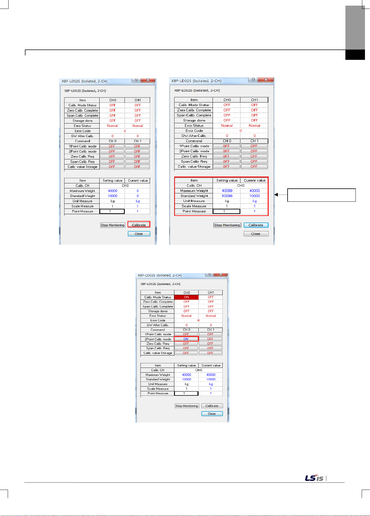
6-5
Enter calibration parts
After entering the calibration parts, click 'Calibrate' to display the entered values.
Chapter 6 Functions
After entering the calibrat ion item, c lick 'Request 2-po int Calibration Mo de' to turn it on. 'C alibration Mode Status'
is turned on.
Page 56
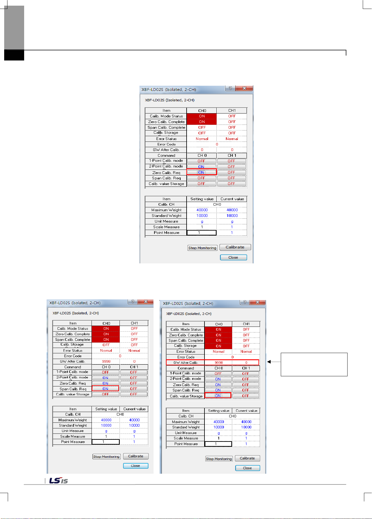
6-6
Chapter 6 Functions
Click 'Request Zero Calibration' with the pallet em pty to turn it on. 'Zero Ca libration Com plete' is turned o n once
the calibration is complete.
Place a weight correspon ding to the standard weight, then click 'Request Span Calibration' to turn it on. 'Span
Calibration Complete' is turned on once the calibration is complete. Confirm the gross weight value after
calibration, then click 'Calb. Value Storage.'
Gross Weight V alue
after Calibration
Page 57
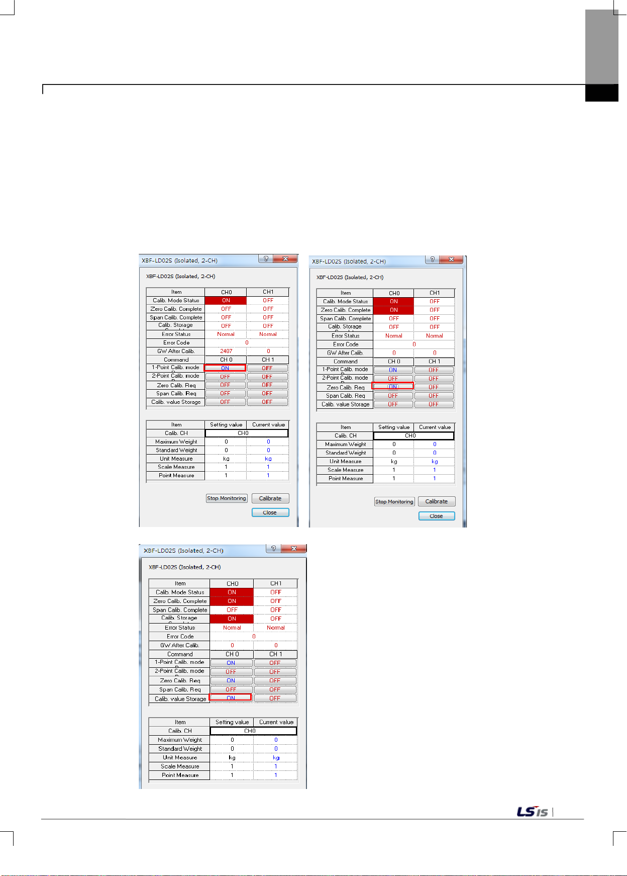
6-7
Chapter 6 Functions
To repeat calibration, repeat the calibration after turning off 'Request 2-point Calibration Mode.'
Save and close the calibration window to apply the calibrated weight values.(Before closing the calibration
window, turn off 'Request 2-point Calibration')
4) Calibration on XG5000 Special Module Monitor Window (1-point calibration)
1-point calibration s hould be p erformed af ter completi ng 2-point ca libration.Turn on Requ est 1-point C alibration
Mode. And Zero Calibration mode, 'Calibration Mode Status' and 'Zero Calibration Complete' are turned on.
Then, click 'Calb. Value Storage and c lose the calibra tion window to appl y the calibrated weight values.(Bef ore
closing the calibration window, turn off 'Request 1-point Calibration')
Page 58
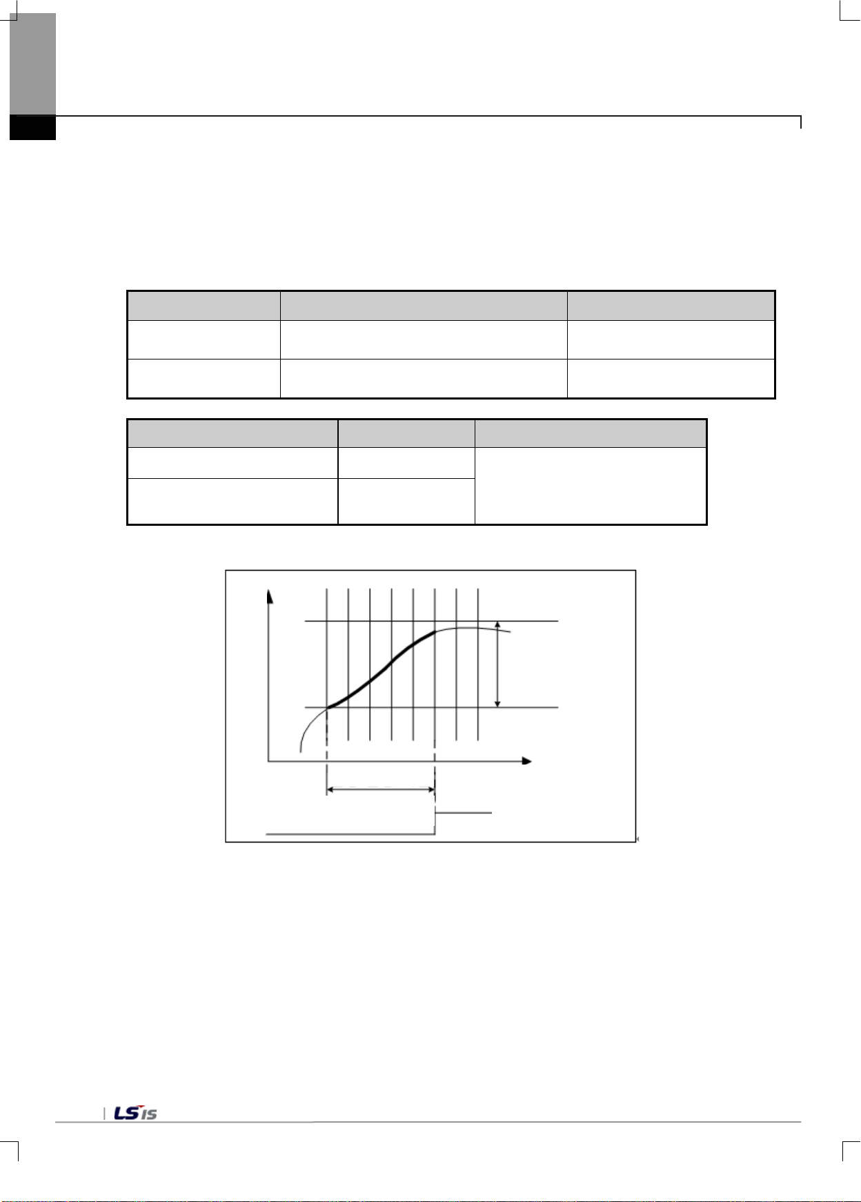
6-8
Stability Determ ination
Range
Channel 0:Address 14
Channel 1: Address 15
Stability Determ ination
Time
Channel 0: Address 16
Channel 1: Address 17
OFF: Stability determination
condition is satisfied
Stability determination
time
OFF
ON
Chapter 6 Functions
6.1.2 Stable Status Determination
It determines whether the status of the gross wei ght values is safe. If the gross weight values are within the
stability determinati on range, and kept with in the r ang e f or longer t han the stability determination time, the st able
status flag is turned on. If even one of the gross weight values exceeds the stability determination range for
longer than the stability determination time, the stable status flag is turned off.
Setting Items Set Values Running Parameter Address
0~999 (x minimum unit scale standard),
1~99 (×100ms)
Items U Device Symbol Description
Channel 0 stable status flag _0y_CH0_STBL
Channel 1 stable status flag _0y_CH1_STBL
W
e
i
g
h
t
c
h
a
n
g
e
[Stable Status Determination Diagram]
condition is being performed
ON: Stability determination
Weight change
Time
Time
Stable status flag
Page 59
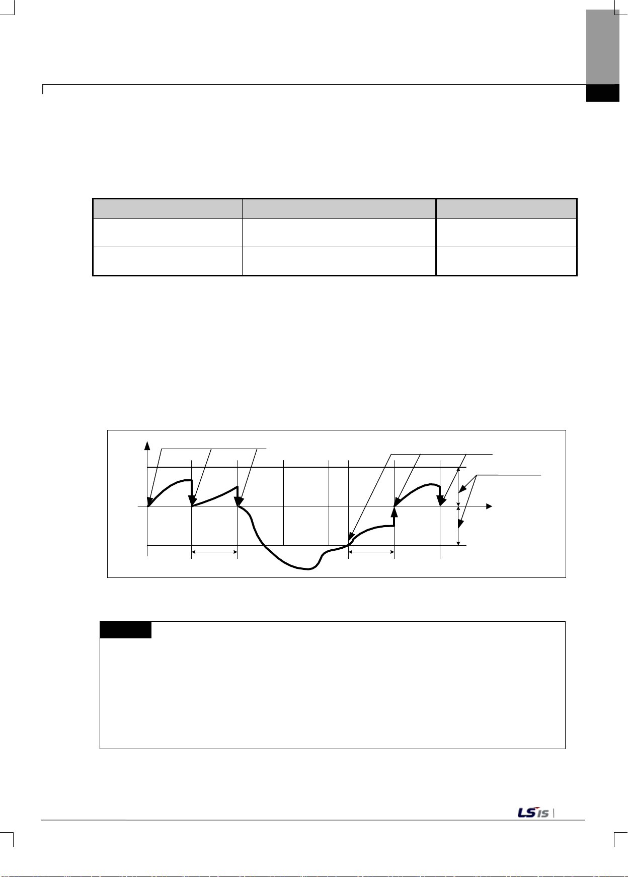
6-9
0
1~99(×minimum unit scale standard)
Channel 0: Address 18
Channel 1: Address 19
Channel 0: Address 20
Channel 1: Address 21
W
e
i
g
h
t
C
h
a
h
g
e
Time
0
Zero tracking start
Zero tracking start
Zero tracking time Zero tracking time
Zer o tr ac king range
1) If an object (weight) with a weight value less than the zero tracking range is plac ed on the pallet,
6.1.3 Zero Tracking Function
It adjusts zero output values in acc ordance w ith changes of the surr ounding en vironm ent, such as tem perature
change. If the zero point s lightl y cha nges af ter cal ibrati on or zer o sett ing, a weight within th e zero tr ack ing range
is automatically adjusted to 0.
Setting Items Set Values Running Parameter Address
Zero Tracking Setting range
Zero Tracking Setting Time 1~99(×100ms)
1) Zero Output Stop
After setting the zero trac king settin g range and tim e, if the gross weight exc eeds the zero tr acking s etting
range or a value exceeding the zero track ing setting ra nge is input, the out put valu e will not be 0.
2) Zero Output Repeat
If the following conditions are satisfied, zero tracking is automatically repeated.
If the gross weight is within the zero tracking setting range, and satisfies both the zero tracking setting
range and time, the output value is 0.
Chapter 6 Functions
[Zero Tracking Diagram]
Remark
the zero tracking func tion will adjust the weight valu e to 0.When placing a light object, set the zero
tracking setting range at 0 to measure the weight value of the object, then set the zero tracking
setting range at a value less than the weight of the object.
Example) If the maximum weight is calibrated at 100g, and a single scale is 1g, and the zero
tracking range is set at 10 and the zero tracking time is set at 30, a 5-g object on the pallet will show
up as weighing 0.In such case, set the zero setting range at 3 or below.
Page 60
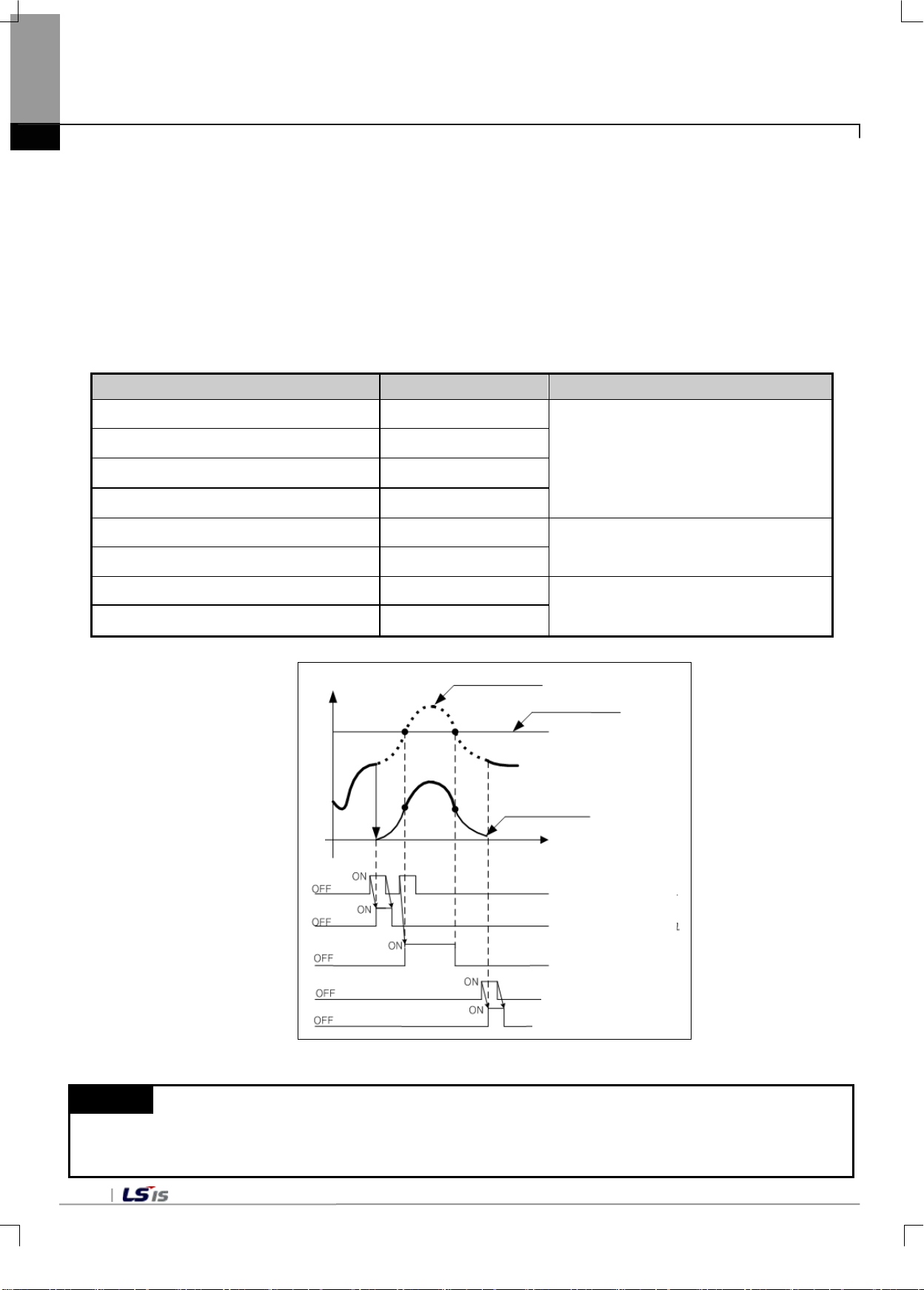
6-10
Load cell output signal
e
Weight conversion value
Zero setting request flag
error flag
error flag error flag
Time
Time
Zero setting complete flag
Time
Chapter 6 Functions
6.1.4 Zero Setting, Reset
It temporarily adjus ts zero output values when 0 is not out put even after 2-point calibration due to changes of
the surrounding environment such as gathering of foreign matters around the pallet caused by using the load cell
for a long time. When using a container (Tare), you can also use this function to remove the weight of the
container.
When resetting the displa yed weight to zero, you can perform the setting within the near zero setting range.
Near zero can be set a t 1 ~ 99% of the maximum weight. If th e gross weight exce eds th e n ear zero s ett ing r a nge,
an error occurs when setting the zero point.
Items U Device Variable Description
Channel 0 zero setting request flag _0y_CH0_ZSETREQ
Channel 1 zero setting request flag _0y_CH1_ZSETREQ
Channel 0 zero reset request flag _0y_CH0_ZRSTREQ
Channel 1 zero reset request flag _0y_CH1_ZRSTREQ
Channel 0 zero setting complete flag _0y_CH0_ZSET
Channel 1 zero setting complete flag _0y_CH1_ZSET
Channel 0 zero setting complete flag _0y_CH0_ZRST
Channel 1 zero setting complete flag _0y_CH1_ZRST
W
e
i
g
h
t
c
h
a
n
g
OFF: No zero setting /res et r equest
ON: Zero setting/reset request
OFF: Zero setting not complete
ON: Zero setting complete
OFF: Zero setting not complete
ON: Zero setting complete
Remark
1) If the PLC power is o n, t he currently measured v al ue w ith in t he near zer o s ett ing range is automatical ly set
as the zero point. The pallet must be emptied and the PLC power must be turned on before use.
[Zero Setting Reset Function Diagram (zero tracking range: 0)]
Page 61
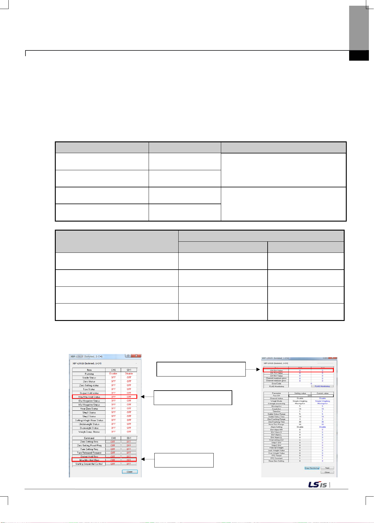
6-11
Channel 0 maximum/minimum
maintenance request flag
Channel 1 maximum/minimum
maintenance request flag
Channel 0 maximum/minimum
maintenance status flag
Channel 1 maximum/minimum
maintenance status flag
_0y_CH0_GWMAX_H (upper)
_0y_CH0_GWMIN_L (lower)
_0y_CH0_GWMIN_H (upper)
_0y_CH0_GWMAX_L (lower)
_0y_CH0_GWMAX_H (upper)
_0y_CH0_GWMIN_L (lower)
_0y_CH0_GWMIN_H (upper)
Minmax Hold Status Flag
Minmax Hold Flag
Minmax gross weight value
6.1.5 Maximum / Minimum Value Output Function
It displays the m aximum / m inimum values of the gross weight measur ed while runn ing the input channel. T he
maximum / minimum values are automatically stored into the corresponding U device. If the maximum /
minimum request f lag is on, the maximum / m inimum values at the time of turning the flag on are displa yed. If
the maximum / m inimum reques t flag is turned off, the m aximum / minimum values at the tim e of tur ning the f lag
off are maintained.
Items U Device Variable Description
Chapter 6 Functions
_0y_CH0_MAXMINREQ
_0y_CH1_MAXMINREQ
_0y_CH0_MAXMINHLD
_0y_CH0_MAXMINHLD
Items
Channel 0 maximum value of gross weight
Channel 0 minimum value of gross weight
Channel 1 maximum value of gross weight
Channel 1 minimum value of gross weight
You can view the maximum/m inim um m aintenance re ques t flag, s tatus f lag, and t he m aximum /m inimum weight
values on the special module monitor window.
_0y_CH0_GWMAX_L (lower)
OFF: Release maximum/minimum request
ON: Maximum/minimum request
OFF: Maximum/minimum maintenance
release status
ON: Maximum/minimum maintenance status
U Device Variable
XBC IEC
_0y_CH0_GWMAX
_0y_CH0_GWMIN
_0y_CH1_GWMAX
_0y_CH1_GWMIN
Page 62
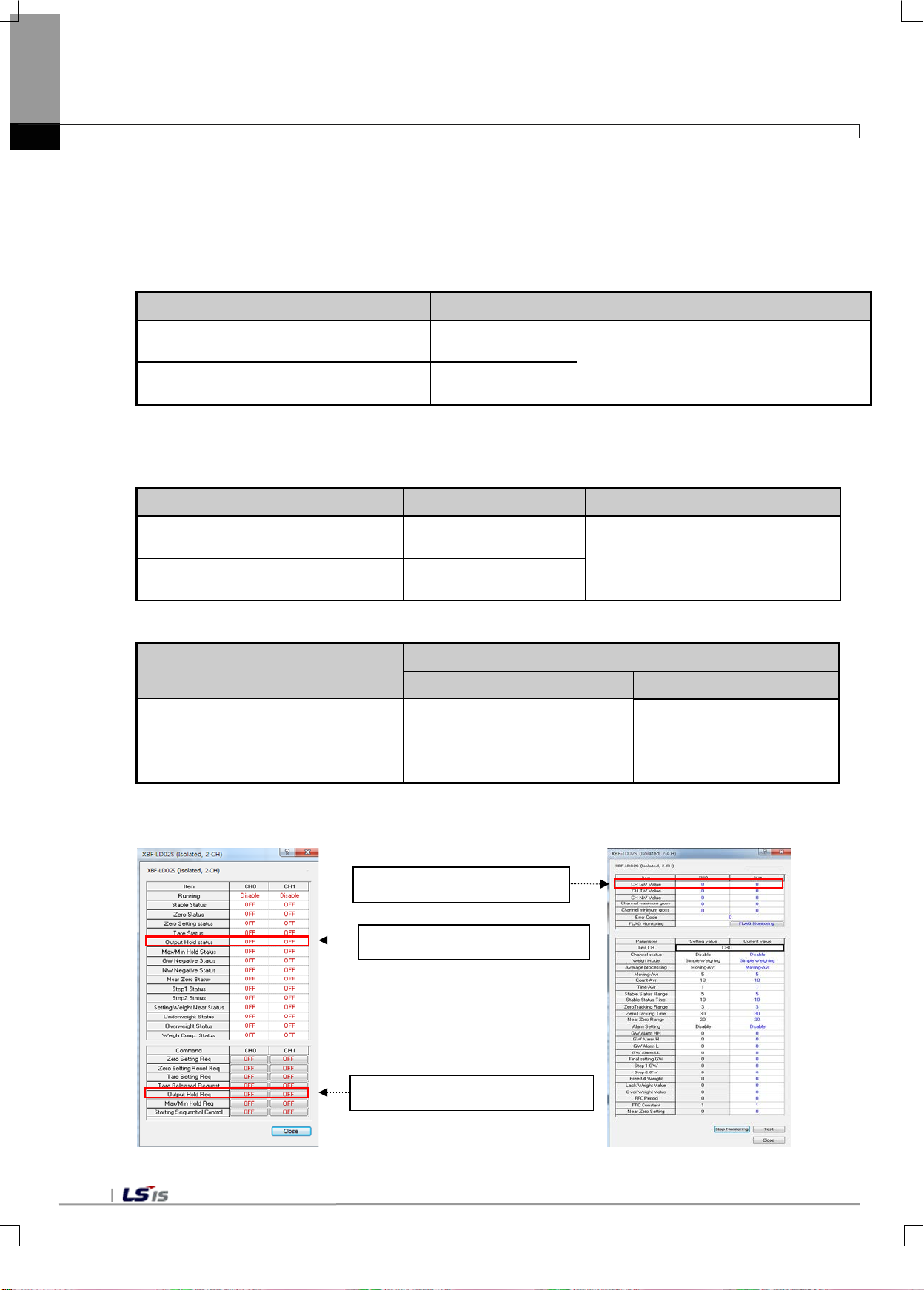
6-12
Channel 0 gross weight value maintenance
request flag
Channel 1 gross weight value maintenance
Output maintenance status flag
Channel gross weight value
Chapter 6 Functions
6.1.6 Output Value Maintenance Function
It temporarily mainta ins th e outp ut va lue of the gr oss weig ht. It is ex ecuted onl y when the out put status request
flag is turned on.
Items U Device Variable Description
request flag
_0y_CH0_HOLDREQ
_0y_CH1_HOLDREQ
OFF: Release Output value maintenance
function
ON: Set output value maintenance function
The status flags maintained when the output value hold request flag is on, and the output values are as follows.
1) Output Maintenance Status Flag
Items U Device Variable Description
Channel 0 output maintenance status
flag
Channel 1 output maintenance status
flag
_0y_CH0_WEIGHTHLD
_0y_CH1_WEIGHTHLD
OFF: Release output value
maintenance status
ON: Output value maintenance status
2) Output maintenance gross weight value
U Device Variable
Items
XBC XEC
Channel 0 output maintenance gross
weight value
Channel 1 output maintenance gross
weight value
_0y_CH0_GWDATA_L (lower)
_0y_CH0_GWDATA_H (upper)
_0y_CH1_GWDATA_L (lower)
_0y_CH1_GWDATA_H (upper)
_0y_CH0_GWDATA
_0y_CH1_GWDATA
You can view the output maintenance request flag, status flag, and the gross weight values on the special module monitor
window.
Output maintenance request flag
Page 63
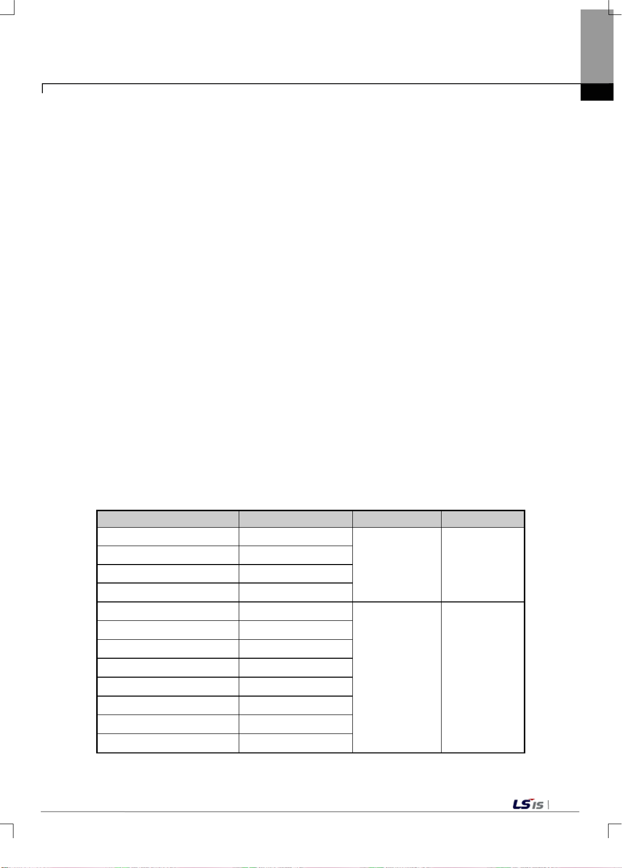
6-13
6.1.7 Alarm Output Function
It alerts the user when the gross weight reaches the preset alarm value range.
1) Alarm Condition
(1) Alarm L
Alarm L is set off if the gross weight is the same as or below the 'GW Alarm LL' value.
(2) Alarm H
Alarm H is set off if the gross weight is the same as or above the 'GW Alarm HH' value.
2) Alarm Release Condition
(1) Alarm L
Alarm L is released if the gross weight is higher than 'GW Alarm L.'
(2) Alarm H
Alarm H is released if the gross weight is higher than 'GW Alarm H.'
3) Status Flag Condition
(1) LL Status
LL status flag occurs if the gross weight is the same as or below the set
'GW Alarm LL' value.
(2) L Status
L status flag occurs if the gross weight is the same as or below the set
'GW Alarm L' value
(3) H Status
H status flag occurs if the gross weight is the same as or above the set
'GW Alarm H' value
(4) HH Status
HH status flag occurs if the gross weight is the same as or above the set
'GW Alarm HH' value
Items U Device Description LED Status
Chapter 6 Functions
Channel 0 Alarm H flag _0y_CH0_HOOR
Channel 1 Alarm H flag _0y_CH1_HOOR
Channel 0 Alarm L flag _0y_CH0_LOOR
Channel 1 Alarm L flag _0y_CH1_LOOR
Channel 0 HH Status Flag _0y_CH0_HHOORSTAT
Channel 0 H Status flag _0y_CH0_HOORSTAT
Channel 0 L Status flag _0y_CH0_LOORSTAT
Channel 0 LL Status flag
Channel 1 HH Status Flag
Channel 1 H Status flag
Channel 1 L Status flag
Channel 1 LL Status flag
_0y_CH0_LLOORSTAT
_0y_CH1_HHOORSTAT
_0y_CH1_HOORSTAT
_0y_CH1_LOORSTAT
_0y_CH1_LLOORSTAT
OFF: Normal
ON: Alarm occurs
OFF: Normal
ON: Status occurs
Blinks at 1second intervals
Lighting Status
Page 64
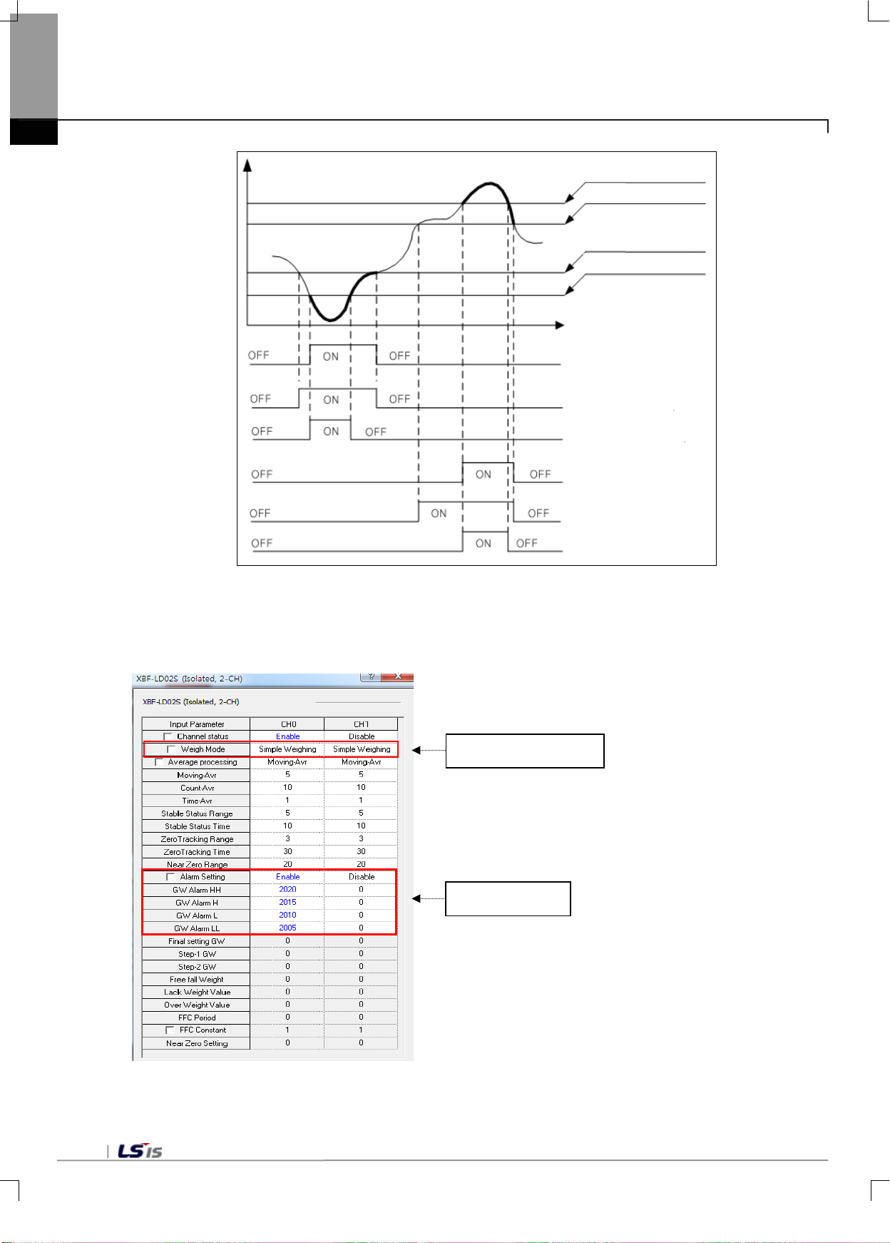
6-14
Alarm HH set value
Time
Alarm LL set value
Alarm L flag
L status flag
LL status flag
Alarm H flag
H status flag
HH status flag
Chapter 6 Functions
[Alarm Output Diagram]
You can set alarm values at I/O parameter, and use it when the weigh mode is set at 'simple weigh.'
Weigh Mode Setting
Alarm Setting
Page 65
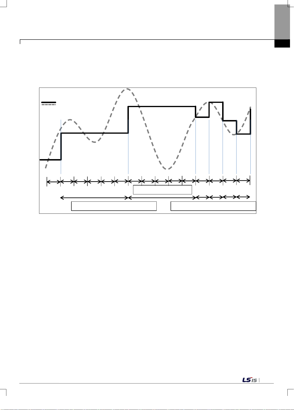
6-15
Channel scan interval(5ms)
Count average processing section(5)
Input value after average processing
Inpu t v alue after
moving average processin g
Count average processing section(1)
㎳
6.1.8 Average Processing Function
1) Count/Moving Average
It calculates the m oving average of the input values of the designated channel, accumulates for the
set counts, and displays the average of the sum as digital data.
Chapter 6 Functions
- Setting Range = 1 ~ 999[counts]
- Initial Value: 10
In case of count average, the average processing interval is calculated regardless of the number of
channels used.
Average Processing Interval [
] = average counts ×5㎳
Page 66
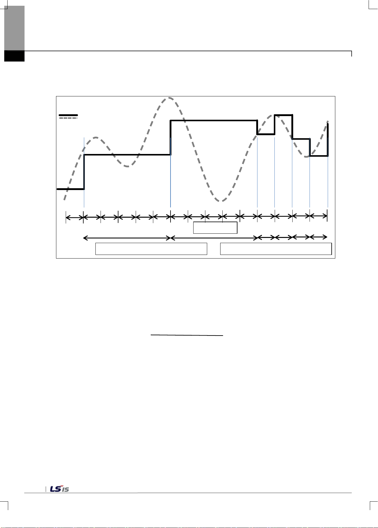
6-16
Interval(100ms)
Time average processing section(500ms)
Input value after average processing
Inpu t v alue after
moving average processin g
Time average processing section(100ms)
Counts of average[counts]=
5㎳
Set average timex100[㎳]
Chapter 6 Functions
2) Time Average
It calculates the m oving average of the input valu es of the design ated channel, and ac cumulate for the s et
counts, and display the average of the sum as digital data.
- Setting Range = 1 ~ 999[×100㎳]
- Initial Value: 1
The minimum unit of time average is 100ms, and the average processing interval is calculated
regardless of the num ber o f channe ls used. As the co nversion c ycle within the module is 5ms , the actua l
counts of average processing are as follows.
Page 67
6-17
3) Moving Average
Moving average is an average processing method of adding the difference between the current value
and the previous moving average divided by 2
moving average, average values are displayed at each scan within the module.
- set number of moving averages = 3~9
- Average number of moving averages = 2
- Initial Value: 5 (2
Moving average values are output in accordance with the following formula.
Chapter 6 Functions
n
to the previous averaging average value. In case of
set number of moving averages
5
)
( 23~29)
Moving average value (n) = moving average value(n-1) + (current value – moving average
value (n-1) + remainder (n-1))/ 2
n
Remainder (n) = current value - moving averag e val ue (n-1)
Page 68
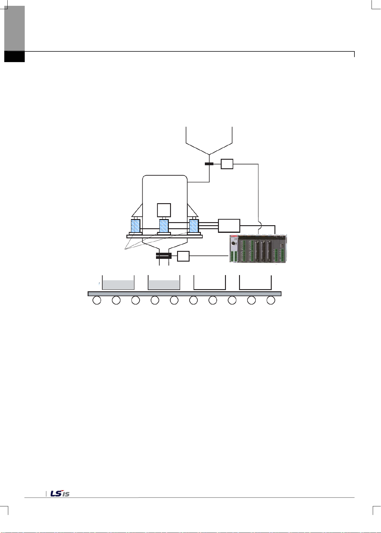
6-18
XBF-LD02S
Raw material
tank
Supply valve
(ste p1, ste p2, ste p3
Load cell
Weighing tank
Junc tio n
box
Discharge valve
Container
Belt conveyor
Chapter 6 Functions
6.1.9 Free Fall Compensation function
When the weigh m ode is supply (simple com parison, sequential com parison) and disc harge (simple comparis on,
sequential comparison), it compensates the free fall value before reaching the final setting weight value. The
following sections show an actual example of application.
1) System Composition Example
(1) If a near zero signal is detected, perform tare setting to remove the tare weight.
(2) Open the supply valve to begin raw material supply from the raw material tank to the weighing tank.
(3) When the weight reaches the final set value – step 1, the step 1 signal is out put. Using this signal, the supply
valve is closed by half.
(4) When the weight reaches the f inal set value - step 2, the step 2 s ignal is output. Using this signa l, the supply
valve is closed by more than half.
(5) When the weight reaches the final set value - free fall, the step 3 signal is output, and the supply valve is
completely closed.
(6) When the supply valve i s complete closed, the remaining r a w m ater ia l (f r ee f all) in th e r a w m ater ial tank and the
weighing tank flo ws into the weighing tank . If the final weight add ed with the infl ow amount satisfies the s tability
condition, weighing is complete and the final discharge valve is open. .
(7) Close the discharge valve after discharging the raw material, confirm that the discharge is complete by
detecting near zero signals, and then repeat steps (1) through (6).
Page 69
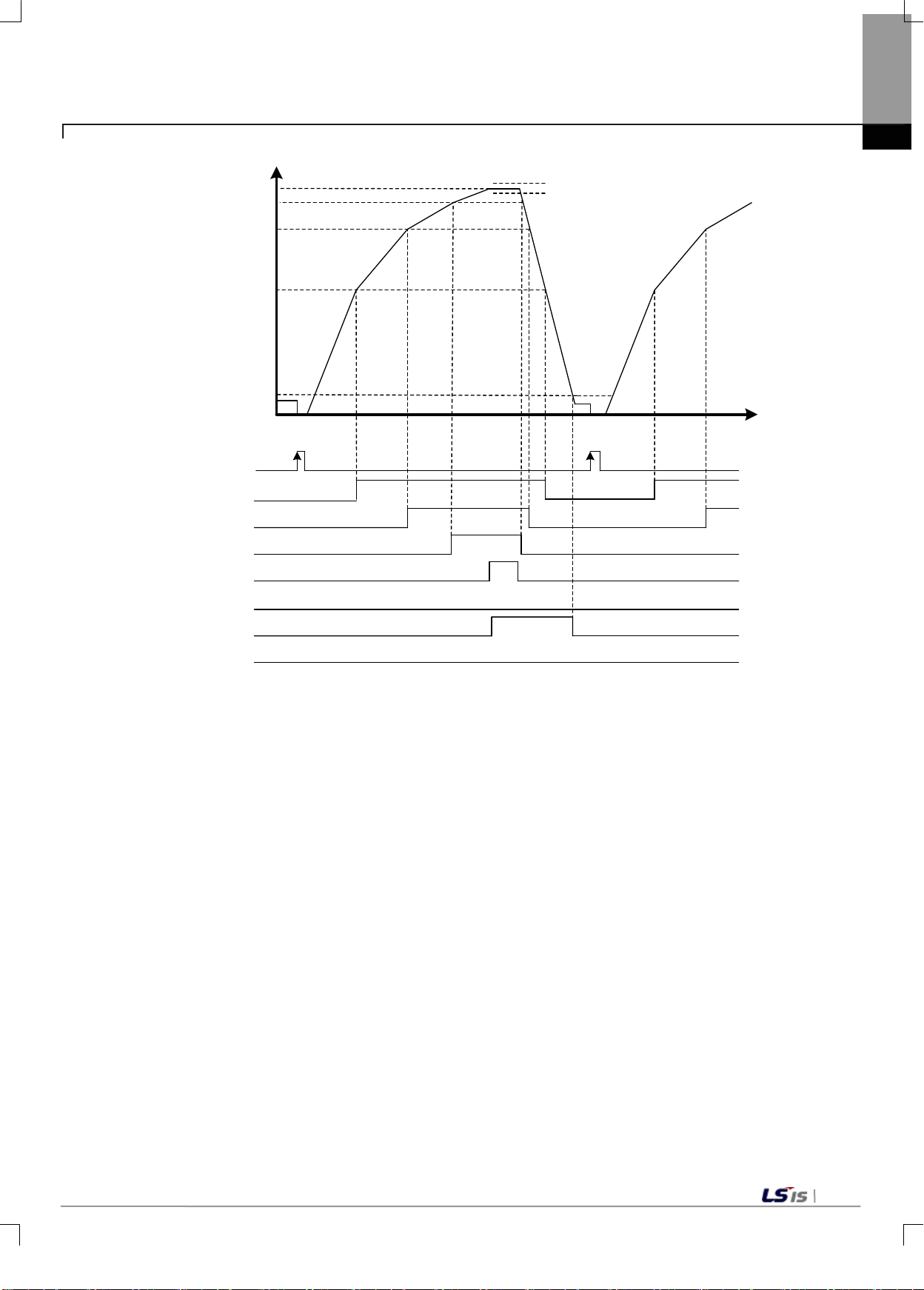
6-19
Time
0
Final set value-fr e e f all
Near zero
OFF
Tare setting
Weight over val ue
Weight la ck va lue
Final set value
Step 1
OFF
ON
Step 2
OFF
Step 3
OFF
Stable status
OFF
Weight over
OFF
Weighing compl ete
OFF
Weight la ck
OFF
ON
ON
ON
ON
ON
Final set value-step2
Final set value-step1
Chapter 6 Functions
·Step 1 Output: Current total weight value >= final set value - step 1 set value
·Step 2 Output: Current total weight value >= final set value - step 2 set value
·Step 3 Output: Current total weight value >= final set value - free fall
·Weight over output: Current total weight value > final set value + weight over value
·Weight lack output: Current total weight value < final set value - weight over value
·Weighing complete: Final set value - weight lack value <= current total weight value <+ final set va lue +
weight over value
Page 70
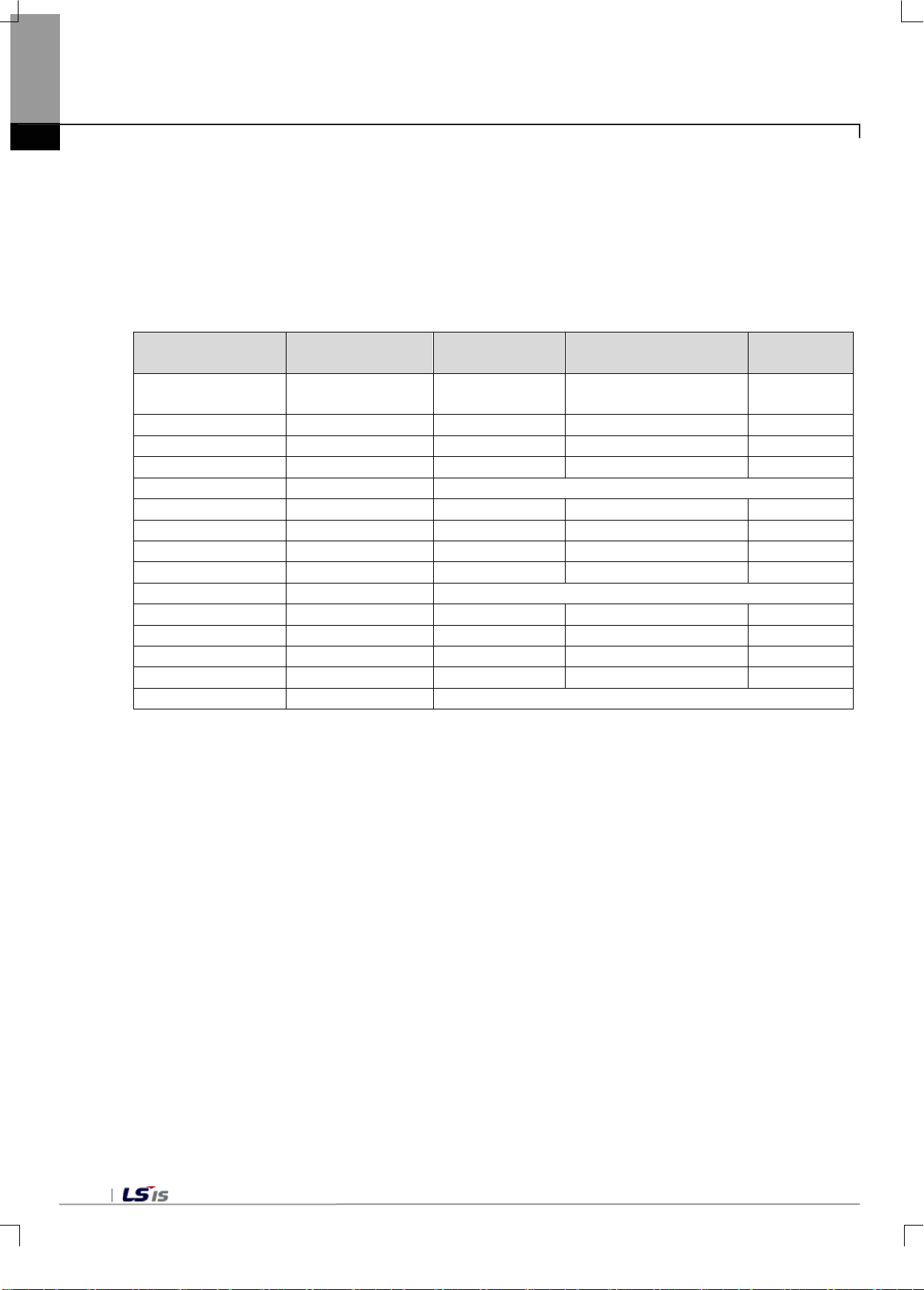
6-20
Number of
measurements
Measured weight
value
Error
Number of free fall
compensations
Free fall
the initial power)
2
20040
+40 2 500
3
20070
+70 3 500 4 20080
+80 4 500
+240/4 = -60 -60*2/4=30 530(free fall)
5
20020
+20 1 530 6 20000
0 2 530
7
20010
+10 3 530
8
20110
+10 4 530
+40/4 = -10 -10*2/4=5 535(free fall)
9
19990
-10 1 535
10
20010
+10 2 535
11
20000
0 3 535
12
19980
-20 4 535
-20/4 = -5 -5*2/4=3 532(free fall)
Chapter 6 Functions
2) Free Fall Compensation
It compensates free fall values. The following sections show an actual example.
[Set Value]
Final set values 20000, free fall compensation value (counts):4 times, free fall compensation factor:2/4, free
fall initial value:500
[Description]
1 (after connecting
When the input free fall compensation value (count) is 4, free fall is compensated if the average value of 4
weighed values is the same as or above the final set value.
·For the first 4 measurements, the measured values are adjusted by 30 by applying a factor of 2/4, as the
weight over value is 60.
·For the following 4 measurements, the measured values are adjusted by 5 by applying a factor of 2/4, as the
weight over value is 10.
·For the following 4 measurements, the measured values are adjusted by -3 by applying a factor of 2/4, as the
weight lack value is -5.
This function calculates the average weight corresponding to the set counts, and increases the free fall value
when the weight exceeds the final set value , and decreases the free fall value when the weight is less than the
target value.
20050 +50 1 500
Page 71
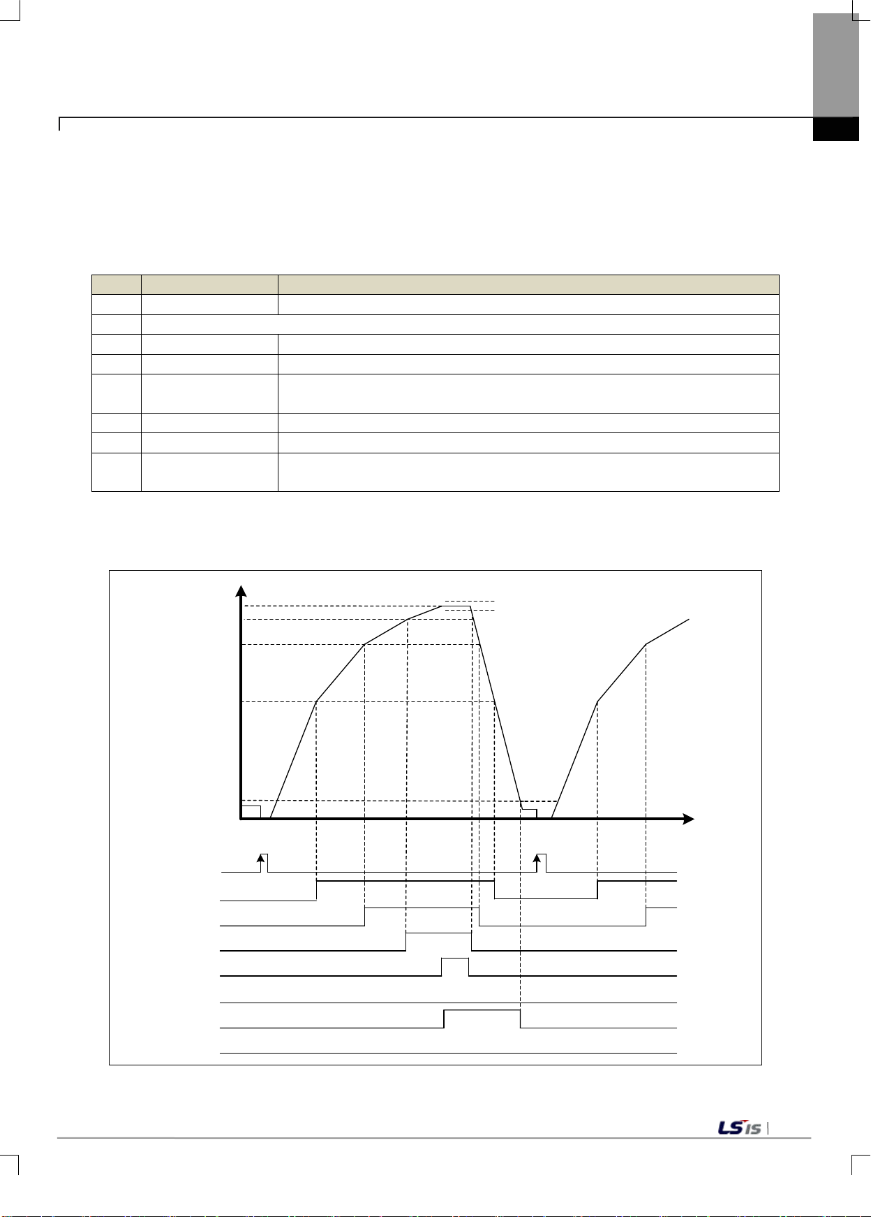
6-21
Order
Flag
Condition
1
Near zero status
Channel total weight value <= near zero ran ge
2
When near zero, request tare setting
3
Step 1 status
Channel net weight value >= final set value - step 1 set value
4
Step 2 status
Channel net weight value >= final set value - step 2 set value
status
6
Weight lack status
Channel net weight value < final set value - weight lack value
7
Weight over status
Channel net weight value > final set value + weight over value
channel net weight value - weight lack value ] & stable status (on)
Time
0
Final set value-fr e e f all
Near zero
OFF
Tare setting
Weight over val ue
Weight la ck va lue
Final set value
Step 1
OFF
ON
Step 2
OFF
Near set weight
OFF
Stable status
OFF
Weight over
OFF
Weighing compl ete
OFF
Weight la ck
OFF
ON
ON
ON
ON
ON
Final set value-step2
Final set value-step1
NET
3) Supply Mode
(1) Simple Comparison
The starting point of simple comparison of the supply mode is when the net value is near zero or below
near zero after tare setting. When the net weight gradually increases, the relevant flag is turned on
depending on the set weight value. The order of progression and the relevant flags are as follows.
Chapter 6 Functions
5
8 Weighing complete
a) In case of weighing complete, the flag timing diagram is as follows.
Setting weight near
Channel net weight value >= final set value - free fall value
[Channel net weight value + weight over value >= channel net weight value >=
Page 72
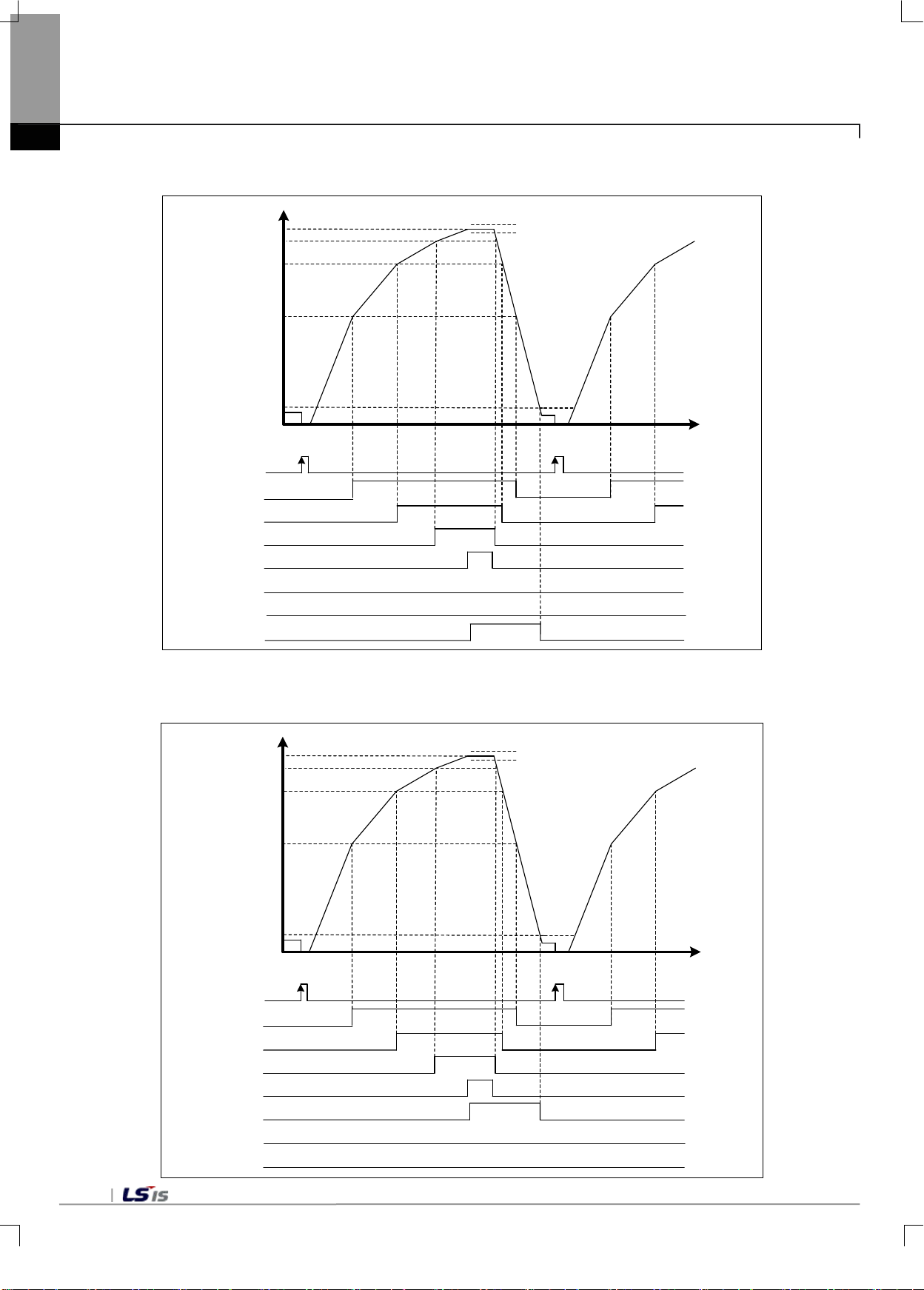
6-22
Time
0
Final set value-fr ee f all
Near zero
OFF
Tare setting
Wei ght ov er val ue
Wei ght lack va l ue
Final set value
Ste p 1
OFF
ON
Ste p 2
OFF
Ste p 3
OFF
Stable status
OFF
Wei ght ov er
OFF
Wei ghi ng c om pl ete
OFF
Wei ght lack
OFF
ON
ON
ON
ON
ON
Final set value-step2
Final set value-step1
NET
Time
0
Final set value-fr ee f all
Near zero
OFF
Tare setting
Wei ght ov er val ue
Wei ght l ack val ue
Final set value
Ste p 1
OFF
ON
Ste p 2
OFF
Ste p 3
OFF
Stable status
OFF
Wei ght ov er
OFF
Wei ghi ng c om pl ete
OFF
Wei ght l ack
OFF
ON
ON
ON
ON
ON
Final set value-step2
Final set value-step1
NET
Chapter 6 Functions
b) In case of weight lack, the flag timing diagram is as follows.
c) In case of weight over, the flag timing diagram is as follows.
Page 73
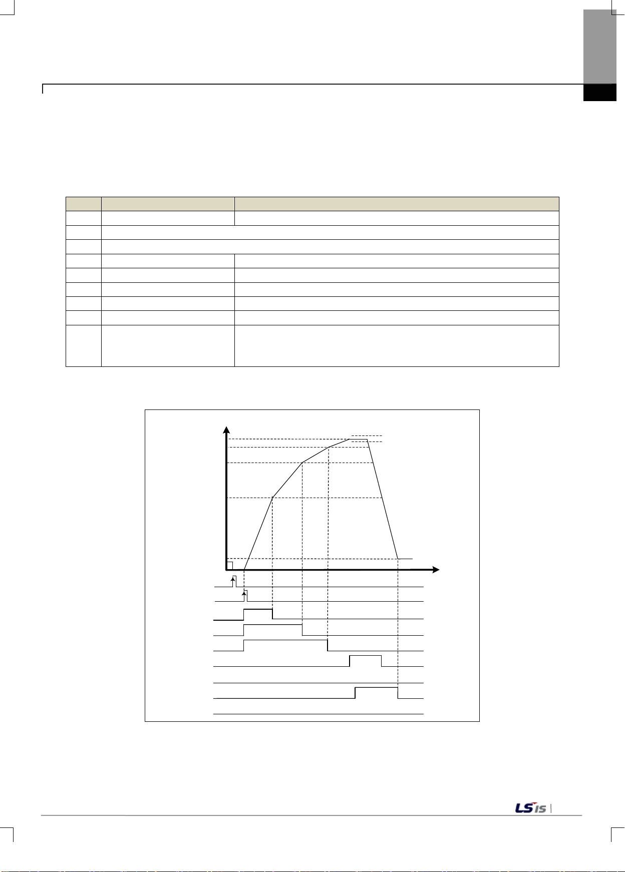
6-23
Order
Flag
Condition
1
Near zero
Channel total weight value <= near zero ran ge
2
When near zero, request tare setting
3
Sequential control start
4
Step 1 status
Channel net weight value >= final set value – step 1 set value
5
Step 2 status
Channel net weight value >= final set value – step 2 set value
6
Setting weight near status
Channel net weight value >= final set value - free fall value
7
Weight lack status
Channel net weight value < final set value - weight lack value
8
Weight over status
Channel net weight value > final set value + weight over value
[Channel net weight value + weight over value >= channel net weight
(on)
Time
0
Final set value-step1
Final set value-step2
Final set value-free f all
Near zero
OFF
Tare setting
Wei ght ov er val ue
Final set value
step1
OFF
ON
step2
OFF
Near set weight
OFF
Stable status
OFF
Wei ght ov er
OFF
Wei ghi ng c om pl ete
OFF
Wei ght lack
OFF
ON
ON
ON
ON
ON
OFF
Seq uentia l
contro l start
ON
NET
Wei ght lack va lue
Chapter 6 Functions
(2) Sequential Control
The starting point of simple comparison of the supply mode is when the net value is near zero or below
near zero after tare setting and the sequential control is initiated. When the net weight gradually increases,
the relevant flag is turned on depending on the set weight value. The order of progression and the relevant
flags are as follows
9 Weighing complete
a) In case of weighing complete, the flag timing diagram is as follows.
value >= channel net weight value - weight lack value ] & stable status
Page 74
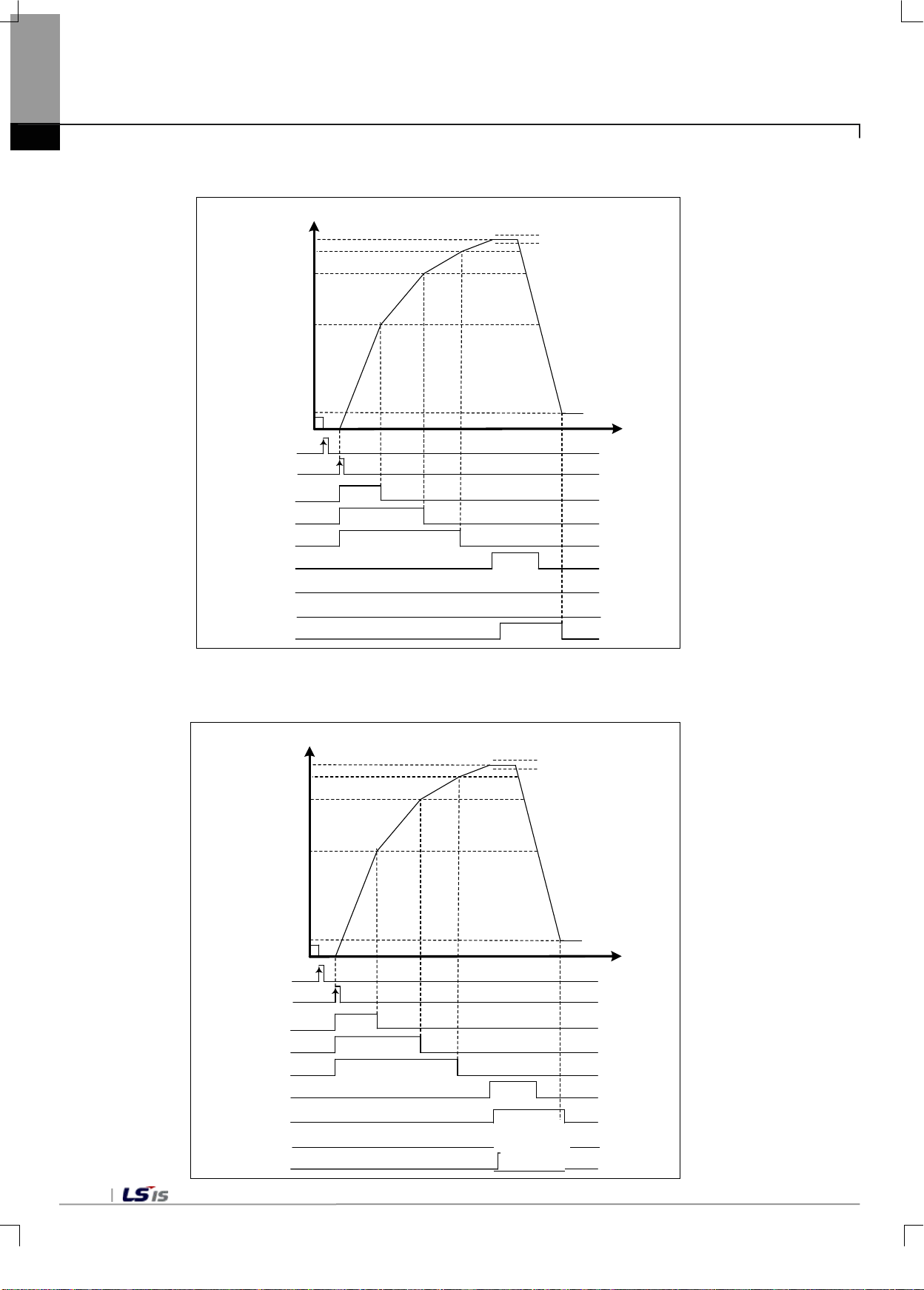
6-24
Time
0
Final set value-st ep1
Final set value-st ep2
Final set value-f ree f all
Near zero
OFF
Tare setting
Wei gh t ov er va lue
Final set value
step1
OFF
ON
step2
OFF
Near set weight
OFF
Stable status
OFF
Wei gh t ov er
OFF
Wei gh i ng c omplete
OFF
Wei gh t lack
OFF
ON
ON
ON
ON
ON
OFF
Seq uentia l
contro l start
ON
NET
Wei gh t lack va lue
Time
0
Final set value-step1
Final set value-step2
Final set value-free f all
Near zero
OFF
Tare setting
Wei gh t ov er va l ue
Final set value
step1
OFF
ON
step2
OFF
Near set weight
OFF
Stable status
OFF
Wei gh t ov er
OFF
Wei gh i ng c ompl ete
OFF
Wei gh t lack
OFF
ON
ON
ON
ON
ON
OFF
Seq uentia l
contro l start
ON
NET
Wei gh t lack va lue
ON
Chapter 6 Functions
b) In case of weight lack, the flag timing diagram is as follows.
c) In case of weight over, the flag timing diagram is as follows.
Page 75
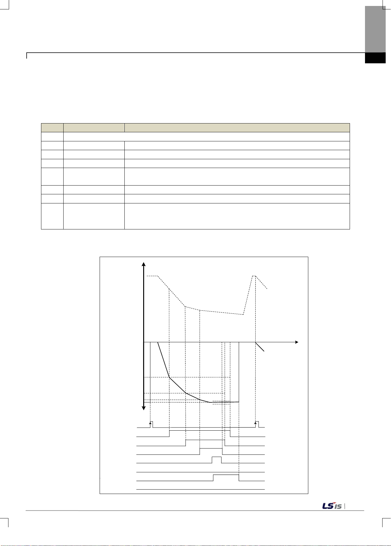
6-25
Order
Flag
Condition
1
Tare setting request, if the tare is filled with raw material
2
Near zero status
Channel net weight value*(-1) <= near zero range
3
Step 1 status
Channel net weight value*(-1) >= final set val ue - step 1 set value
4
Step 2 status
Channel net weight value*(-1) >= final set val ue - step 2 set value
status
6
Weight lack status
Channel net weight value*(-1) < final set value - weight lack value
7
Weight over status
Channel net weight value*(-1) < final set value + weight over value
(on)
0
Final set value-st ep1
Final set value-st ep2
Final set value-f re e f a ll
Near zero
OFF
Tare setting
Final set value
Ste p 1
OFF
NET )
Ste p 2
OFF
Near set weight
OFF
Stable status
OFF
Wei gh t ov er
OFF
OFF
Wei gh t la ck
OFF
ON
ON
ON
ON
ON
Wei gh t la ck v al u e
Wei gh t ov er v al ue
Gross we ight
Time
4) Discharge Mode
(1) Simple Comparison
The starting point of simple comparison of the discharge mode is when the net value is near zero or below
near zero after tare setting with the raw m ater ials filled . W hen the net weight grad ual l y incre ases in the
negative direction, the relevant flag is turned on depending on the set weight value. The order of
progression and the relevant flags are as follows
Setting weight near
5
Chapter 6 Functions
Channel net weight value*(-1) >= final set value - free fall value
8 Weighing complete
a) In case of weighing complete, the flag timing diagram is as follows.
[Channel net weight value *(-1) + weight over value >= channe l net weig ht
value*(-1) >= channel net weight value*(-1) - weight lack value ] & stable status
Page 76
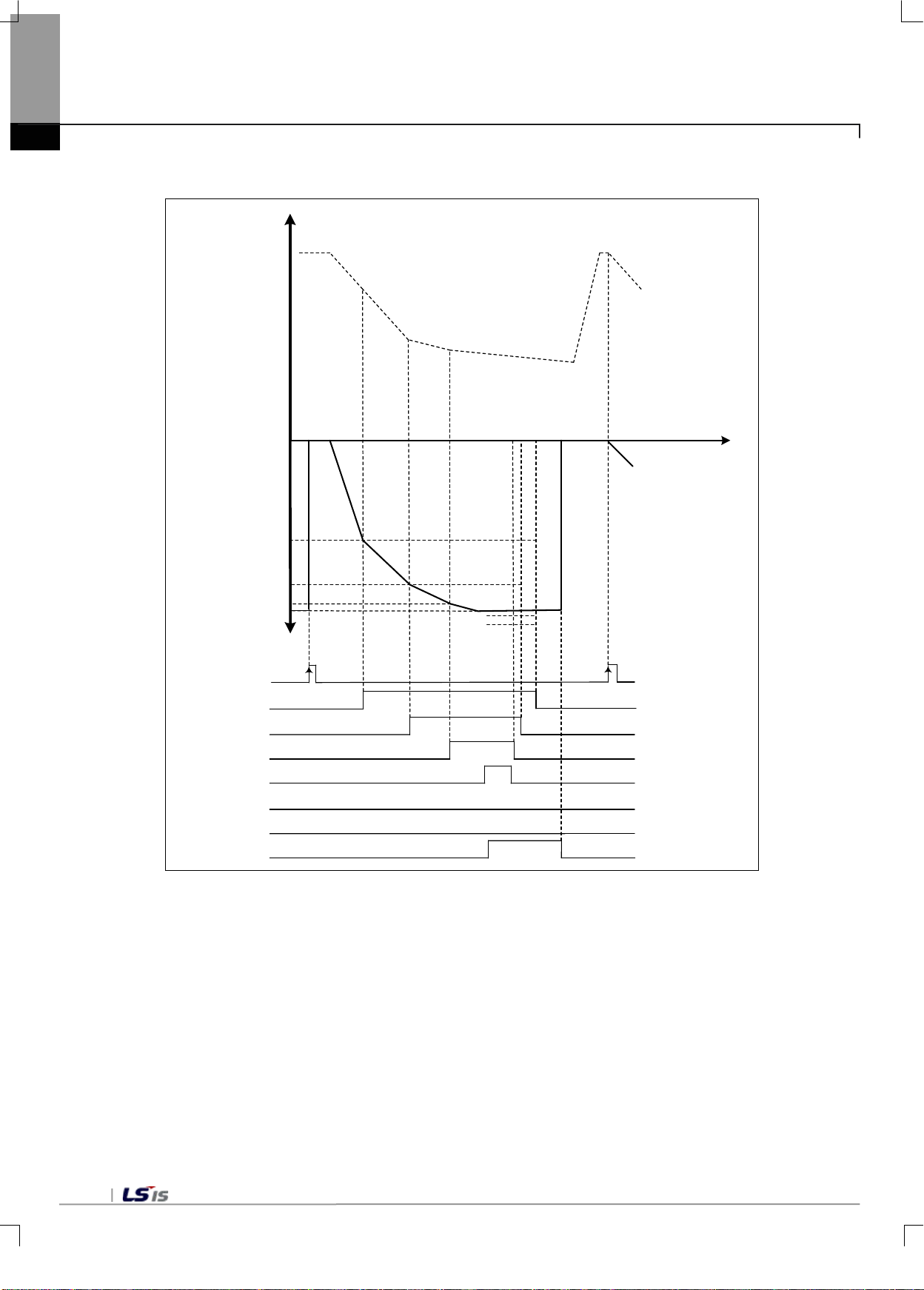
6-26
0
Final set va lue-step1
Final set va lue-ste2
Final set va lue-fr ee fall
Near zero
OFF
Tare s etting
Final set va lue
Step1
OFF
NET
Step2
OFF
Near s et weig ht
OFF
Stable status
OFF
Weight over
OFF
We i ght c om p lete
OFF
Weight lack
OFF
ON
ON
ON
ON
ON
Weight lac k v alue
Weight ov er v alue
Gros s weight
Time
Chapter 6 Functions
b) In case of weight lack, the flag timing diagram is as follows.
Page 77
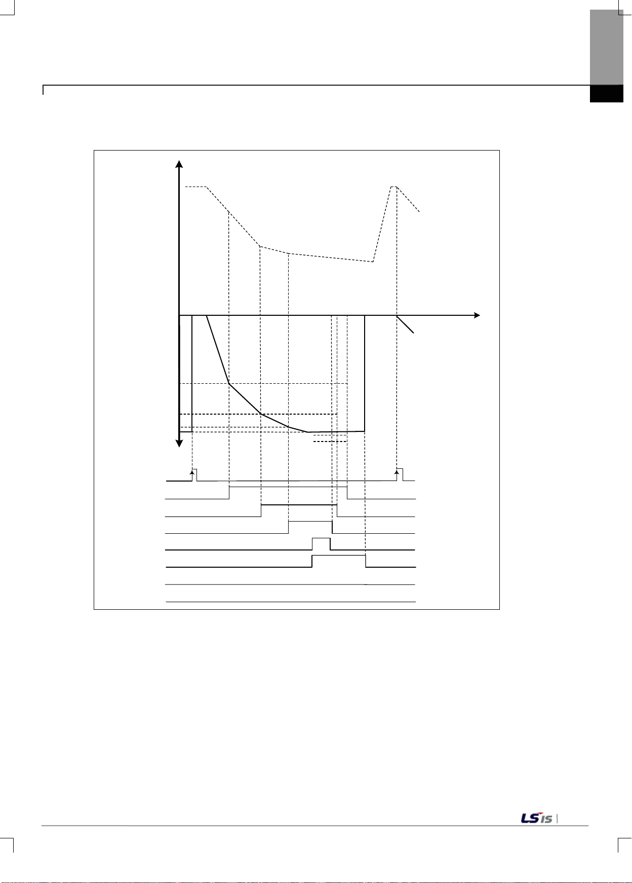
6-27
0
Final set va lue-step1
Final set va lue-ste2
Final set va lue-fr ee fall
Near zero
OFF
Tare s etting
Final set va lue
Step1
OFF
NET
Step2
OFF
Near s et weig ht
OFF
Stable status
OFF
Weight over
OFF
We i ght c om p lete
OFF
Weight lack
OFF
ON
ON
ON
ON
ON
Weight lac k v alue
Weight ov er v alue
Gros s weight
Time
Chapter 6 Functions
c) In case of weight over, the flag timing diagram is as follows.
Page 78
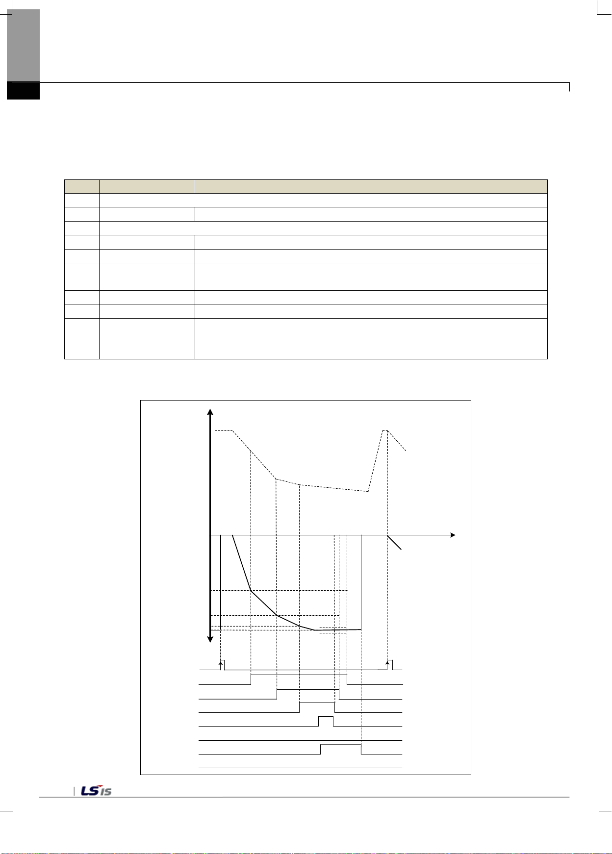
6-28
Order
Flag
Condition
1
Tare setting request, if the tare is filled with raw material
2
Near zero status
Channel net weight value*(-1) <= near zero range
3
When near zero, begin sequential control
4
Step 1 status
Channel net weight value*(-1) >= final set val ue - step 1 set value
5
Step 2 status
Channel net weight value*(-1) >= final set val ue - step 2 set value
Setting weight near
status
7
Weight lack status
Channel net weight value*(-1) < final set value - weight lack value
8
Weight over status
Channel net weight value*(-1) < final set value + weight over value
[Channel net weight value *(-1) + weight over value >= channe l net weig ht
(on)
0
Final set va lue-step1
Final set va lue-step2
Final set va lue-free fall
Near zero
OFF
Tare s etting
Final set va lue
Step1
OFF
NET
Step2
OFF
Near s et weight
OFF
Stable sta tus
OFF
Weight over
OFF
Weighing c om plet e
OFF
Weight lack
OFF
ON
ON
ON
ON
ON
Weight lack v alue
Weight over v alue
Gros s weight
Time
Chapter 6 Functions
(2) Sequential Control
The starting point of simple comparison of the discharge mode is when the sequential control is initiated
near zero after tare setting with the tare fille d with the raw materials. When the net weight gradually
increases in the negative direction, the relevant flag is turned on depending on the set weight value. The
order of progression and the relevant flags are as follows
6
9 Weighing complete
a) In case of weighing complete, the flag timing diagram is as follows.
Channel net weight value*(-1) >= final set value - free fall value
value*(-1) >= channel net weight value*(-1) - weight lack value ] & stable status
Page 79
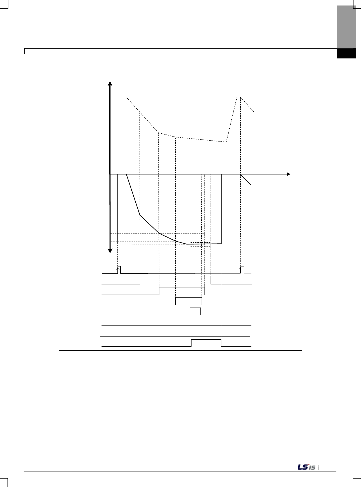
6-29
0
Final set value -step1
Final set value -step2
Final set value -free f all
Near zero
OFF
Tare s ett ing
Final set value
Step1
OFF
NET
Step2
OFF
Near s et weight
OFF
Stable status
OFF
Weight over
OFF
Weighing complete
OFF
Weight lack
OFF
ON
ON
ON
ON
ON
Weight lac k v alue
Weight ov er v alue
Gros s weight
Time
Chapter 6 Functions
b) In case of weight lack, the flag timing diagram is as follows.
Page 80
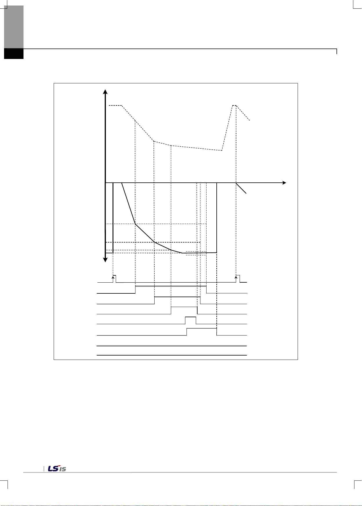
6-30
0
Final set value -step1
Final set value -step2
Final set value -free f all
Near zero
OFF
Tare s ett ing
Final set value
Step1
OFF
NET
Step2
OFF
Near s et weight
OFF
Stable status
OFF
Weight over
OFF
Weighing complete
OFF
Weight lack
OFF
ON
ON
ON
ON
ON
Weight lac k v alue
Weight ov er v alue
Gros s weight
Time
Chapter 6 Functions
c) In case of weight over, the flag timing diagram is as follows.
Page 81
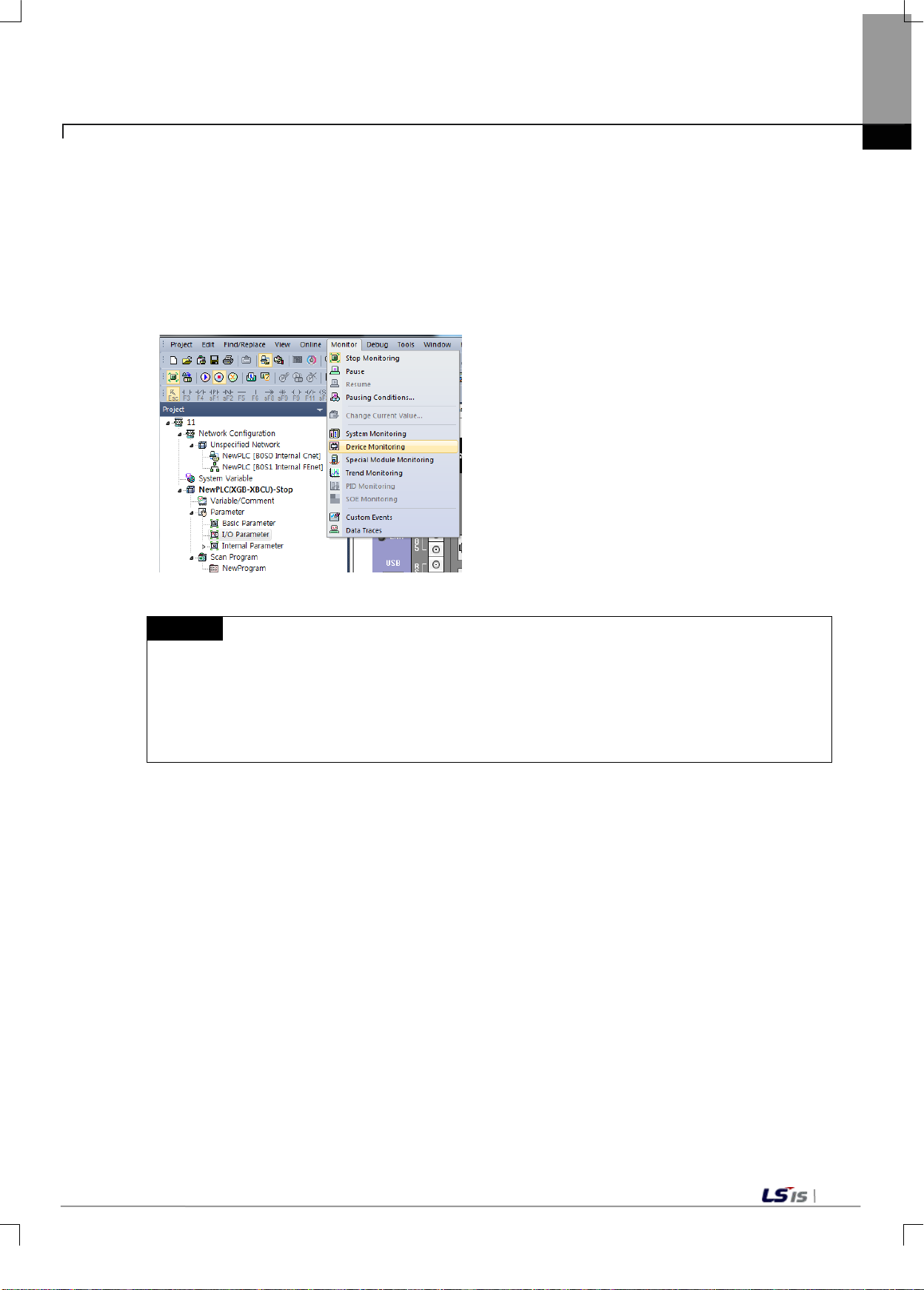
6-31
1) The screen ma y not be displayed norm ally due to ins ufficient system resour ce. In such case, close
analog input module operates normally without writing the sequence program.
6.1.10 Special Module Monitor Function
Functions of the special module monitor are as follows.
1) Running [Special Module Monitor]
Under [Online] -> [Connection] status, go to [Monitor] -> [Special Module Monitor]The [Special Module
Monitor] menu is not enabled unless the status is [Online].
Chapter 6 Functions
Remark
the screen, close the other applications, and run XG5000 once again.
2) The I/O parameters set under [Special Module Monitor] status are set only temporarily for testing.
Therefore, the set I/O parameters are erased once the [Special Module Monitor] status is complete.
3) The test perform ance function of th e [Special Module Monitor] allows t he user to test whether the
Page 82
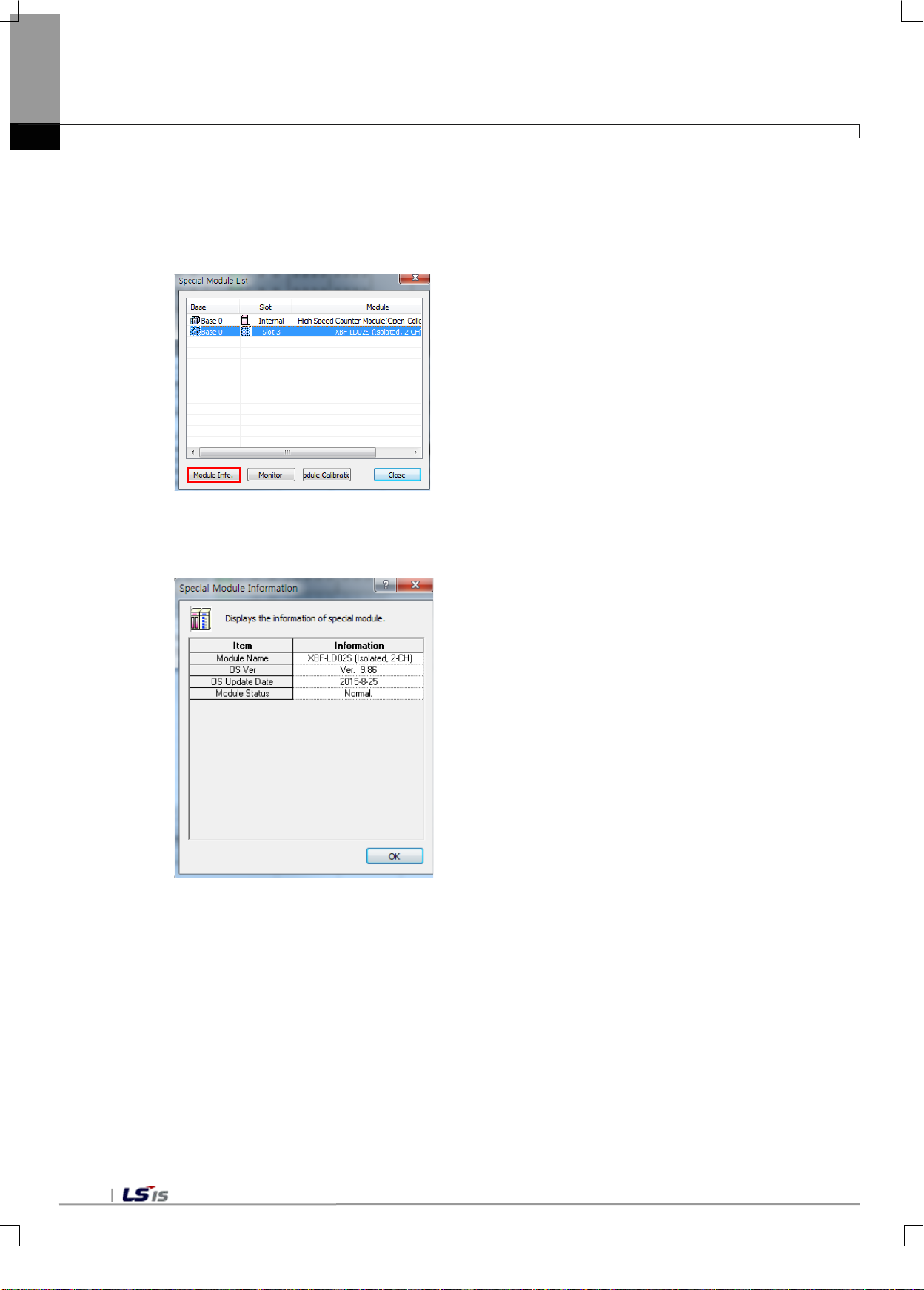
6-32
Chapter 6 Functions
2) Methods on how to use [Special Module Monitor]
(1) With the XG5000 connected to the PLC base unit (on-line), click [Monitor] -> [Speci al Mo dul e Mon itor]I t
displays the [Special Module Monitor] screen shown below, which shows the types of special modules
along with the base/slot information. The list dialogue box displays the modules currently mounted on
the PLC system.
(2) Select a special module and then click [Module Information] to display the following information
Page 83
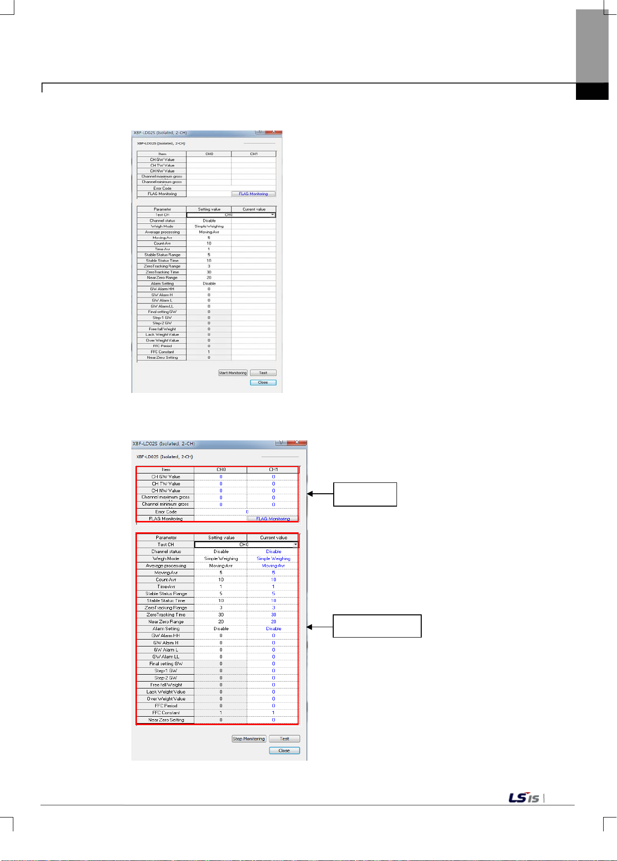
6-33
Monitoring
Chapter 6 Functions
(3) Click [Monitor] on the "Special Module" screen, to display the [Special Module Monitor] screen.
(4) [Start Monitoring]:Click [Start Monitoring] to display the input/output data of the channel currently running.
Channel Details
[Start Monitoring] Execution Screen
Page 84
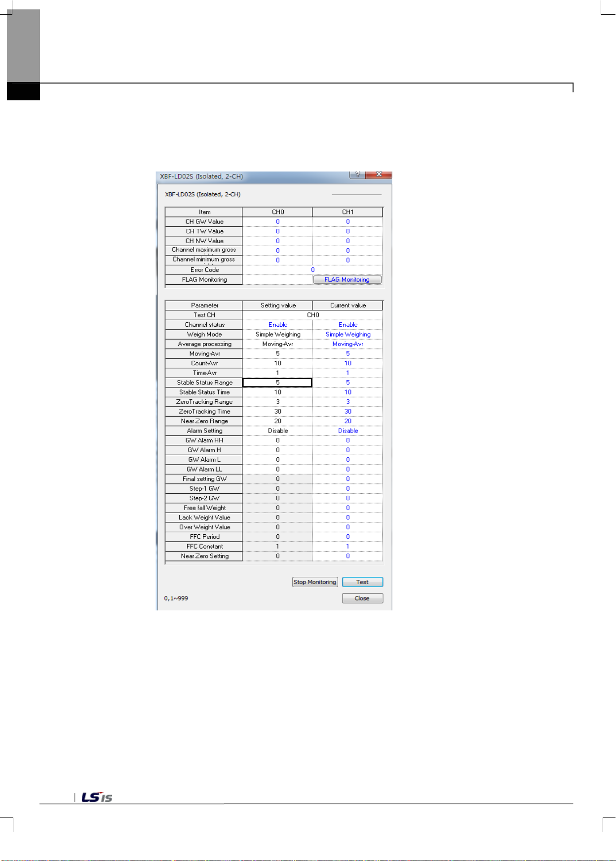
6-34
Chapter 6 Functions
(5) [Test]:[Test] is used when changing the parameters of the currently set module. You can change
parameters by clicking the set values in the fields at the bottom of the screen.[Test] can be enabled
only when the PLC running status is STOP.
[Test] Execution Screen
(6) Close
The [Close] button is used to exit the monitoring/test screen.
The maximum values, minimum values and current values are not stored when the
monitoring/test screen is closed.
Page 85
Wiring
Wiring (Chapter3 Installation and wiring)
Devise programs
Calibration work
Chapter7 Programming (for XBC)
7.1 Setting procedures before running
Verify performance specifications
Chapter7 Programming (for XBC)
Specifications(2.2 performance specifications)
Operating environment
Input range
Digital output range
Power supply wiring (external DC24V power)
Distribution of wires a ccor din g t o
input types
2-point calibration work
Calibration information setting
Calibration mode request
2-point zero calibration request
Span calibration request
Store calibration value
Devise programs
Integrated tool parameter setting
Devise a user program
PLC RUN status
PLC RUN status setting
7-1
Page 86
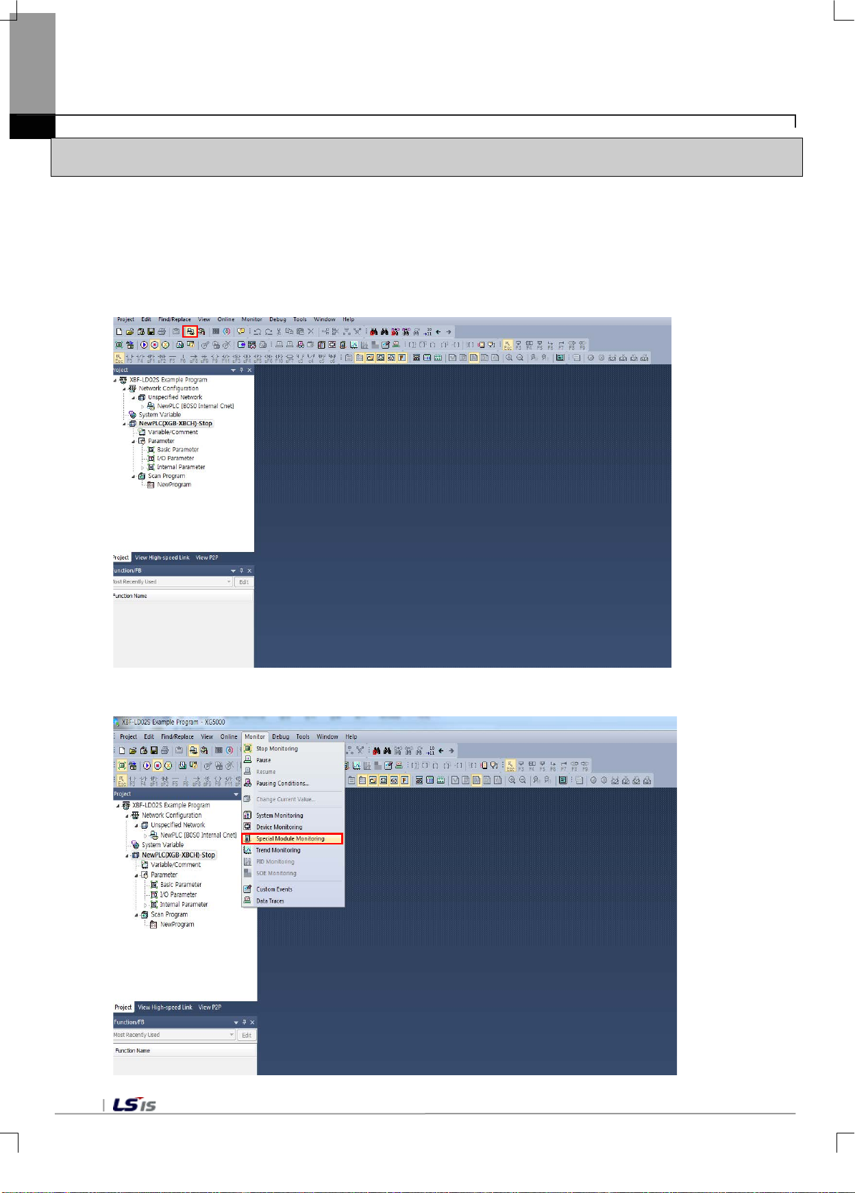
Chapter7 Programming (for XBC)
7.2 Program Example
- The example bel o w s ho ws mounting a load cel l in put module at Slot 1, a nd measuring the wei ght un der the 2point calibration mode through Channel 1.
7.2.1 Calibration Setting
- This section describes how to perform calibration setting.
1) In the XG-5000 software, create a new project and then select [Connect].
2) In the Main Menu, select [Monitor] - [Special Module Monitor].
7-2
Page 87
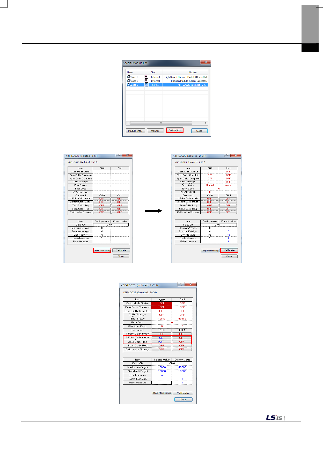
Chapter7 Programming (for XBC)
3) From the special Module List, select the Load Cell Input Module, and then select Module Calibration.
4) Run [Start Mon itoring] , set the max imum weight , the s tandard weight, the scal e and t he decim al point,
and run calibration.
5) After the 2-point calibration mode request, perform zero calibration request.
7-3
Page 88
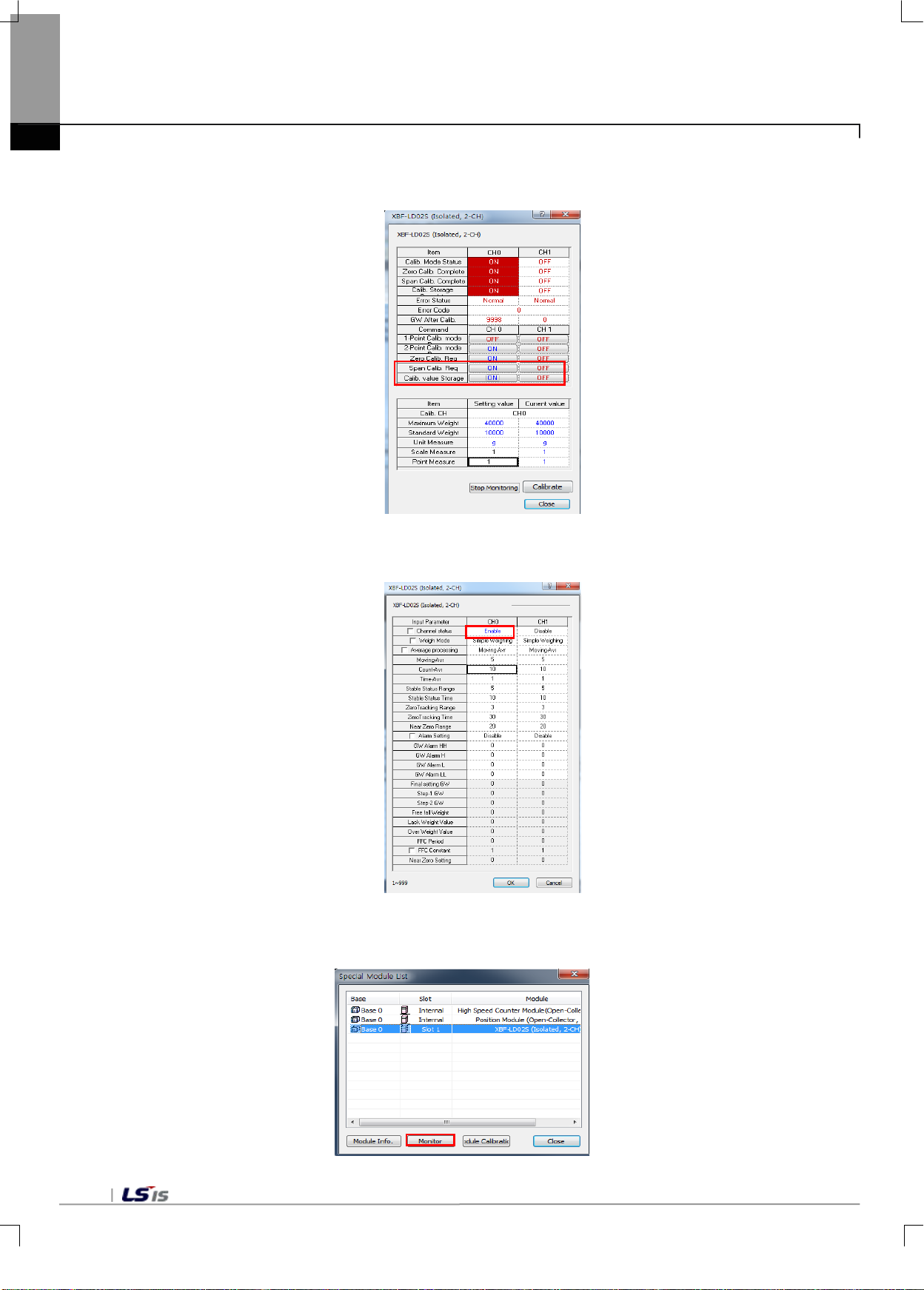
Chapter7 Programming (for XBC)
6) Place a 10kg-counterweight on the load cell, perform span calibration request, and then store the
gross weight value after calibration..
7) From the I/O Param eter on the projec t window, select the load cell in put module, change channel 1 to
running status, and then execute writing..
8) Change the PLC to RUN status, se lect the loa d cell input m odule on the sp ecial module m onitor, and
then execute monitoring.
7-4
Page 89
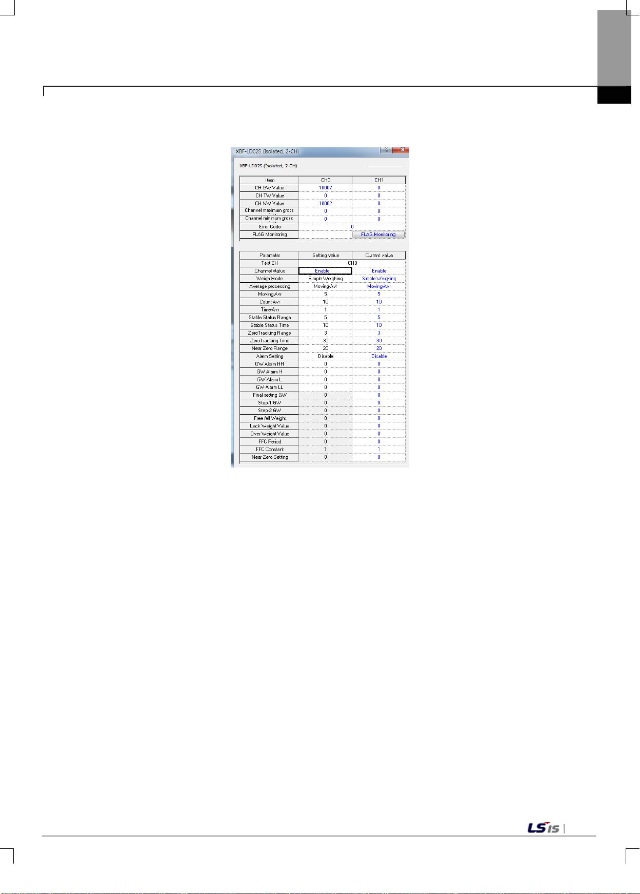
Chapter7 Programming (for XBC)
9) Select Channel 0 and begin monitoring to convert an d display the weight placed on th e load cell into
the preset weight value.
7-5
Page 90
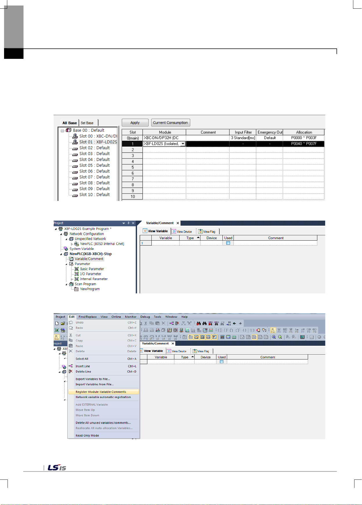
Chapter7 Programming (for XBC)
7.2.2 Autom atic Registration of U Device (Module Variable)
Register the variab les for each module autom atically by referring to the special module inform ation set in [I/O
Parameter]. A user can modify the variables or descriptions.
1) Order of Registration
(1) In [I/O Parameter], set the Load Cell module in the slot.
(2) Double-click [Variables/Comment].
(3) In 'Edit' in the menu, select 'U Device Automatic Registration' (Register Module Variable Comments)
7-6
Page 91
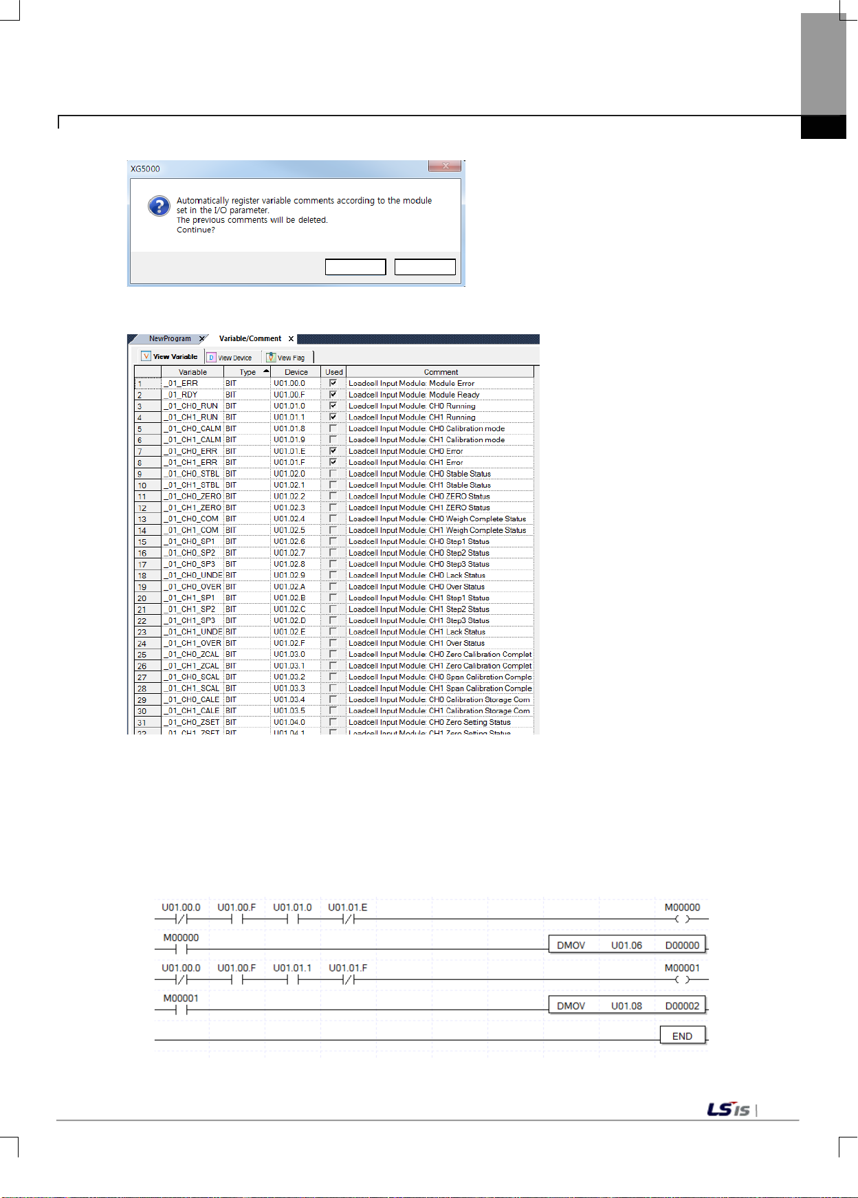
YES
NO
Chapter7 Programming (for XBC)
(4) Click 'Yes.'
(5) Variables are registered as shown below.
2) Store variables
(1) The texts in the 'View Variables' tab can be stored in text files.
(2) In 'Edit' in the menu, click 'Export to Text File.'
(3) The texts in the 'View Variables' tab are stored in text files.
3) View Variables in the Program
(1) The XG5000 example program is as follows.
7-7
Page 92
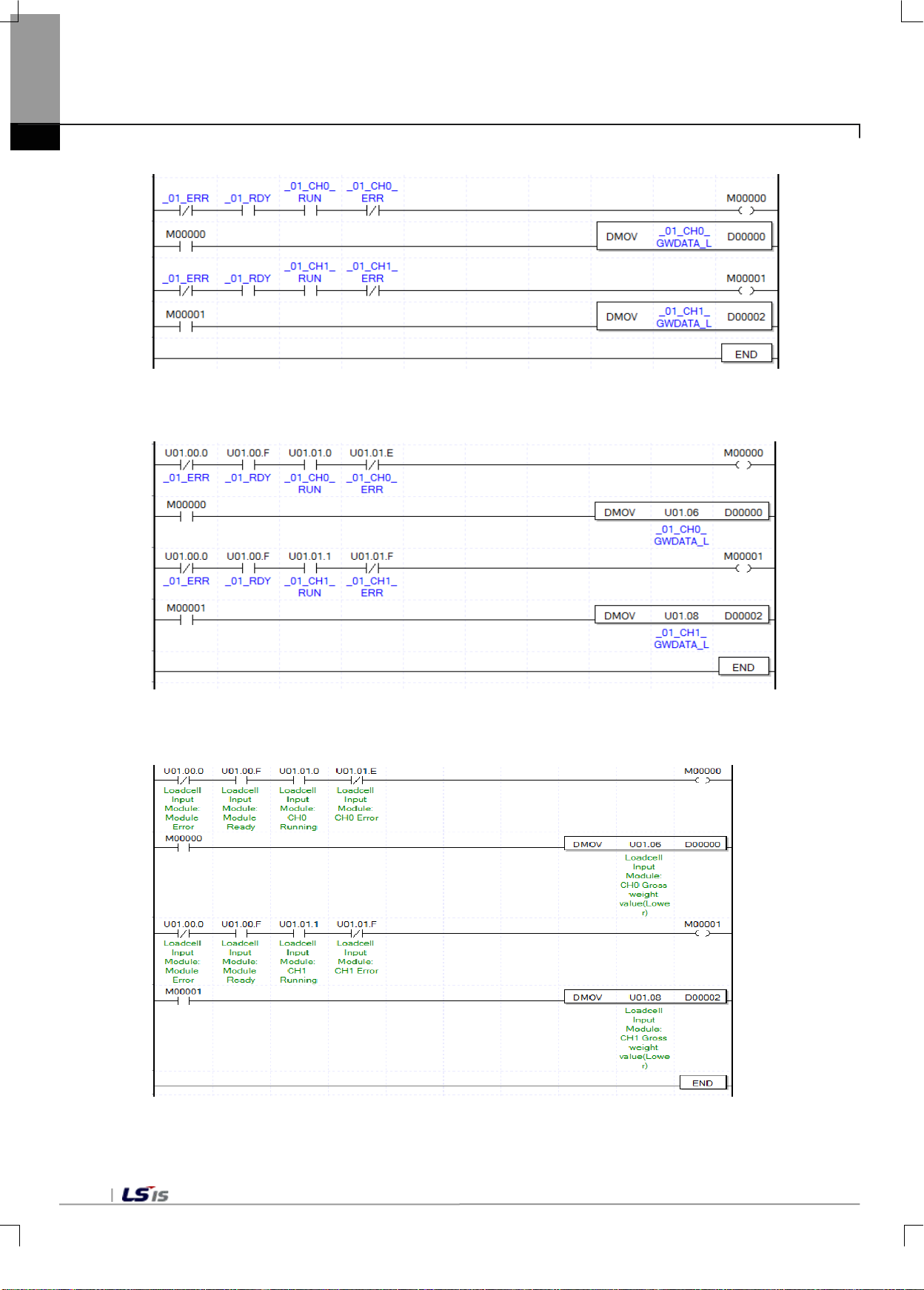
Chapter7 Programming (for XBC)
(2) At 'View' in the menu, click 'View Variables. ‘The devices are changed to variables.
(3) At 'View' in the menu, click 'View Devices/Variables ‘You can view both devices and variables.
(4) At 'View' in the menu, click 'View Devices/Descriptions.' You can view both devices and descriptions.
7-8
Page 93
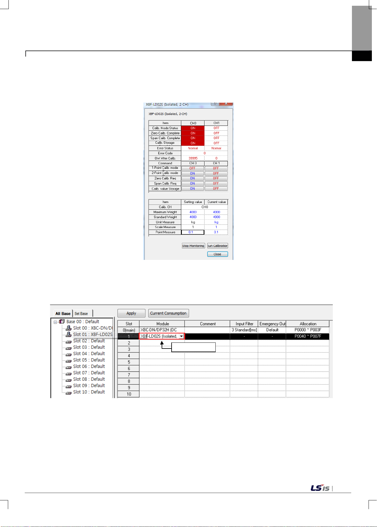
Double click
Chapter7 Programming (for XBC)
7.2.3 Weight Measurement Example
This example shows a program which reads the weight from the ladder program when maximum weight is
4,000kg and the decimal point is 0.1, this program
1) Go to [Monitor ] - [Special Module Monitor] of XG5000. From the spec ial Module List, select the L oad Cell
Input Module, and then select Calibrate Module.
2) Set the maximum weight at 4,000kg, and the decimal point at 0.1 to run calibration.
3) At I/O Parameter, double click the module name to open the parameter setting window.
7-9
Page 94
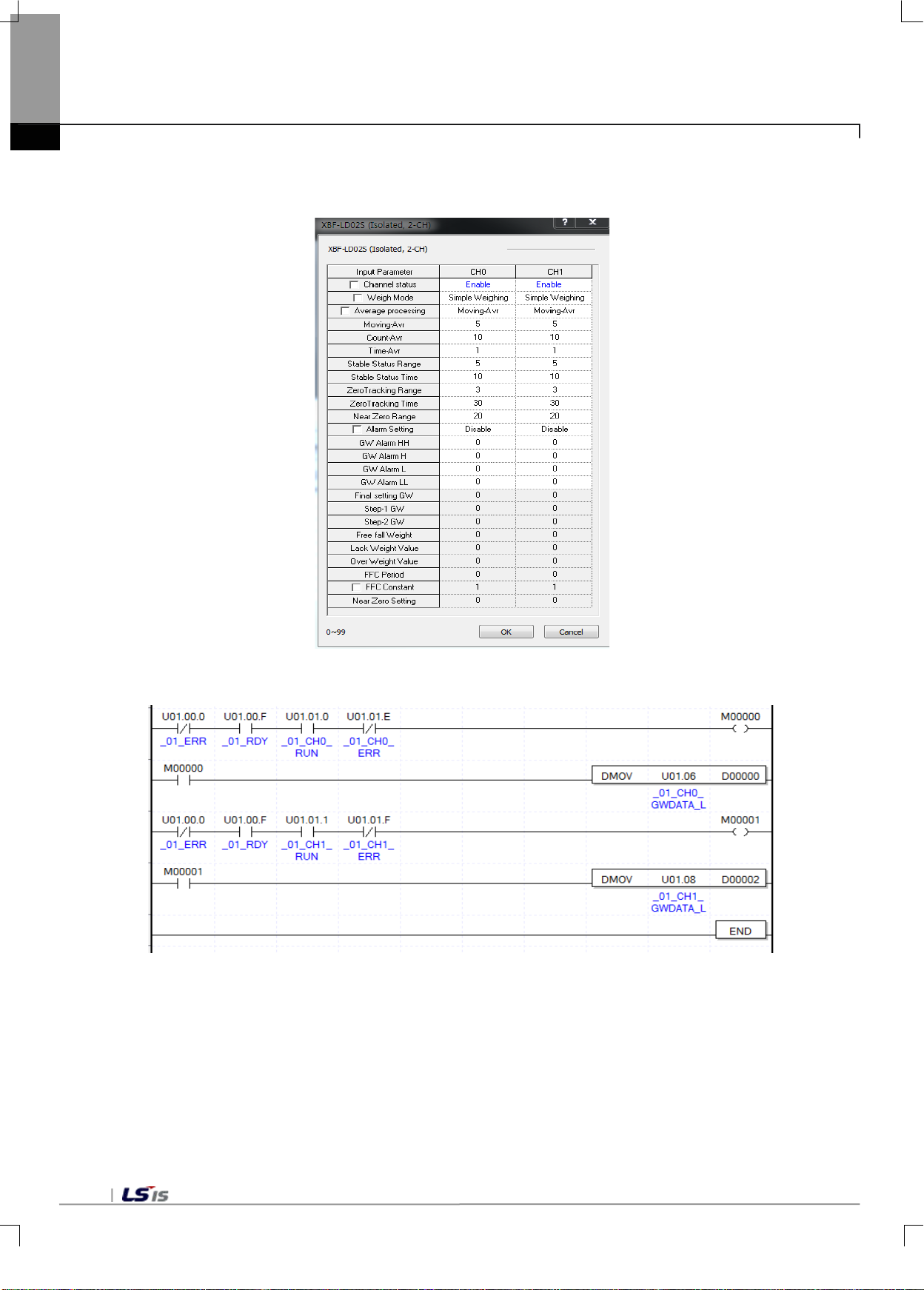
Chapter7 Programming (for XBC)
4) In the setting window, set Channel 0 as running and enable simple weighing.
5) In the setting window, set Channel 1 as running and enable simple weighing.
6) Weight Measurement Program example
(1) If the module is running normally and there is no error in Channel 0, M00000 is on.
U01.00.0(Module Error) = Off
U01.00.F(Module Ready) = On
U01.01.0(Input Channel 0 in Operation) = On
U01.01.E(Input Channel 0 Error) = Off
(2) When M00000 is On, the weight value (U01.06) of Channel 0 is moved to D00000.
7-10
Page 95

Chapter7 Programming (for XBC)
(3) If the module is running normally and there is no error in Channel 1, M00001 is on.
U01.00.0(Module Error) = Off
U01.00.F(Module Ready) = On
U01.01.1(Input Channel 0 in Operation) = On
U01.01.F(Input Channel 0 Error) = Off
(4) When M00001 is on, the weight value (U01.08) of Channel 1 is moved to D00002.
7-11
Page 96
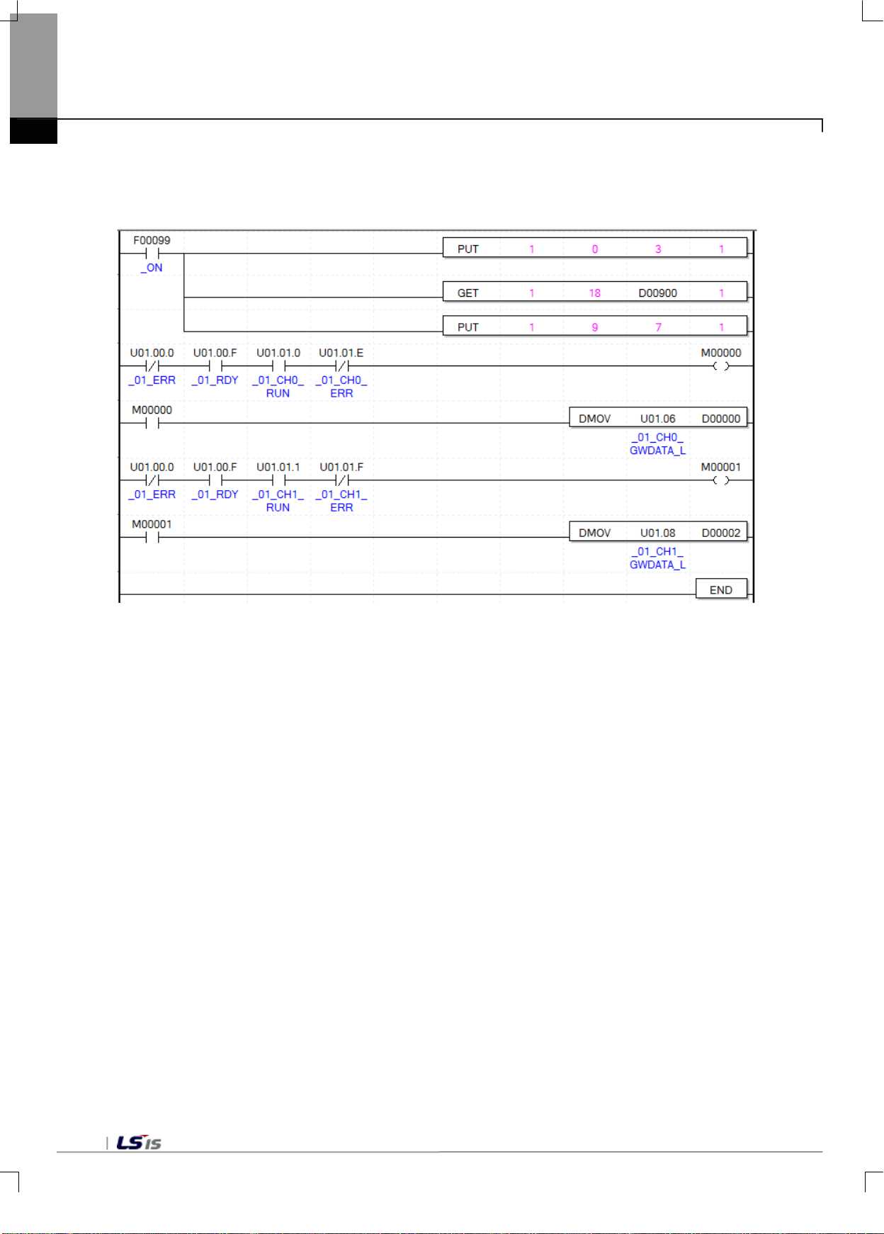
Chapter7 Programming (for XBC)
7.2.4. Using PUT/GET Command
1) Input Program Example
(1) Use the PUT command to write '3' in the Address 0 of Slot 1 to operate Channel 0 and Channel1.
(2) Use the GET command to store the zero tracking range of Slot 1 to D00900.
(3) Use the PUT command to input '7' in Address 9 of Slot 1 to set the moving average value at 7.
(4) If the module is runing normally and there is no error in Channel 0, M00000 is on.
U01.00.0(Module Error) = Off
U01.00.F(Module Ready) = On
U01.01.0(Input Channel 0 in Operation) = On
U01.01.E(Input Channel 0 Error) = Off
(5) When M00001 is on, the weight value (U01.06) of Channel 0 is moved to D00000.
(6) If the module is running normally and there is no error in Channel 1, M00001 is on.
U01.00.0(Module Error) = Off
U01.00.F(Module Ready) = On
U01.01.1(Input Channel 0 in Operation) = On
U01.01.F(Input Channel 0 Error) = Off
(7) When M00001 is On, the weight value (U01.08) of Channel 0 is moved to D000002.
7-12
Page 97
Wiring
Wiring (Chapter 3 Installation and w iring)
Devise programs
Calibration work
Chapter8 Programmi ng (for XEC)
8.1 Setting procedures before running
Verify performance verifications
Chapter8 Programming (for XEC)
Specifications (2.2 performance specifications)
Operating environment
Input range
Digital output range
Power supply wiring (external DC24V power)
Distribution of wires according to
input types
2-point calibration work
Calibration information setting
Calibration mode request
2-point zero calibration request
Span calibration request
Store calibration value
Devise programs
Integrated tool parameter setting
Devise a user program
PLC RUN status
PLC RUN status setting
8-1
Page 98
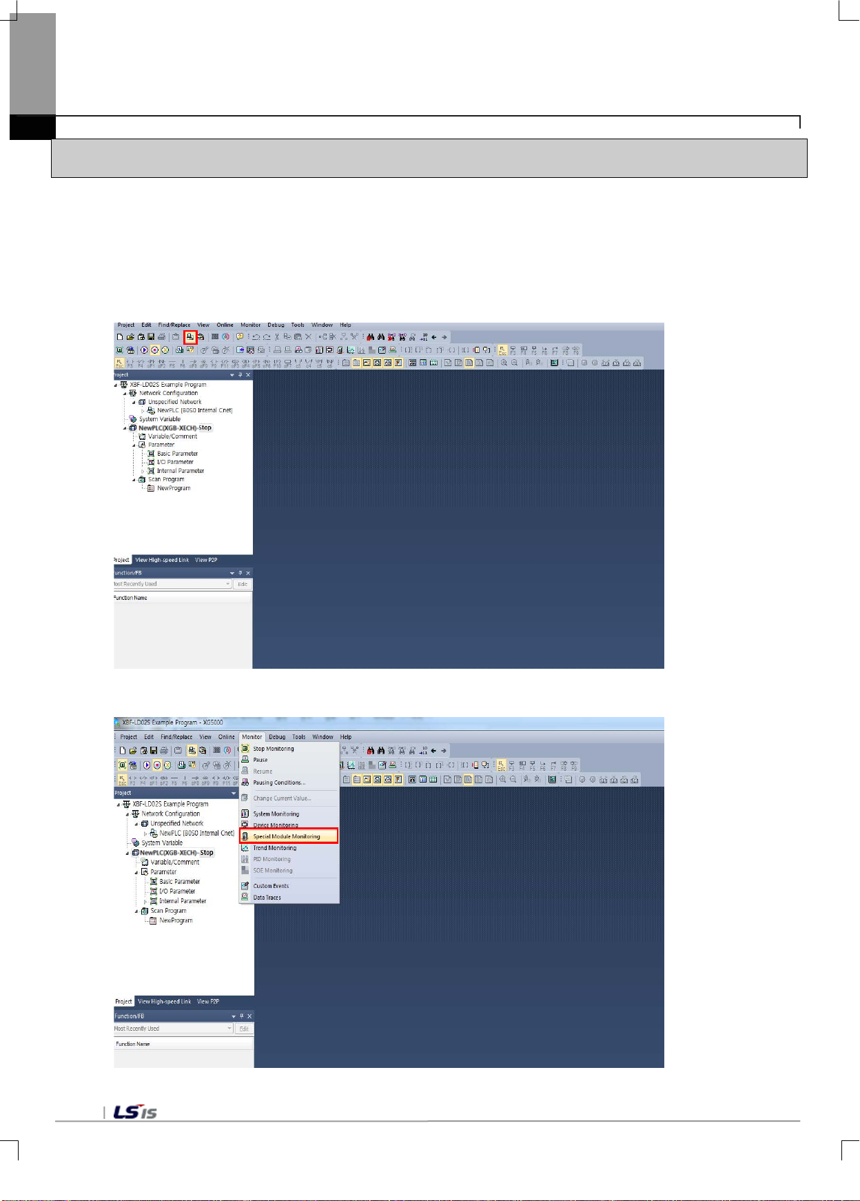
Chapter8 Programming (for XEC)
8.2 Program Example
- The example bel o w s ho ws mounting a load cel l in put module at Slot 1, a nd measuring the wei ght un der the 2point calibration mode through Channel 1.
8.2.1 Calibration Setting
- This section describes how to perform calibration setting.
1) In the XG-5000 software, create a new project and then select [Connect].
2) In the Main Menu, select [Monitor] - [Special Module Monitor].
8-2
Page 99
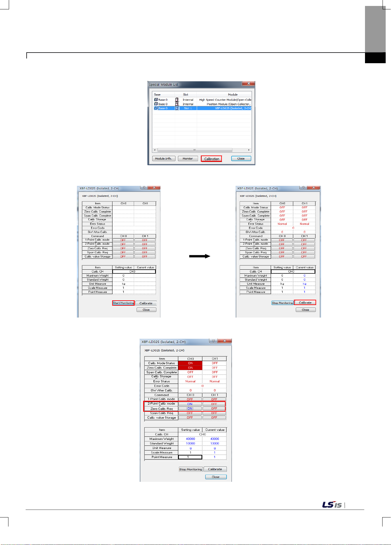
Chapter8 Programming (for XEC)
3) From the special Module List, select the Load Cell Input Module, and then select Calibration.
4) Run [Start Mon itoring] , set the max imum weight , the s tandard weight, the scal e a nd the decim al po int,
and calibrate.
5) After the 2-point calibration mode request, perform zero calibration request.
8-3
Page 100
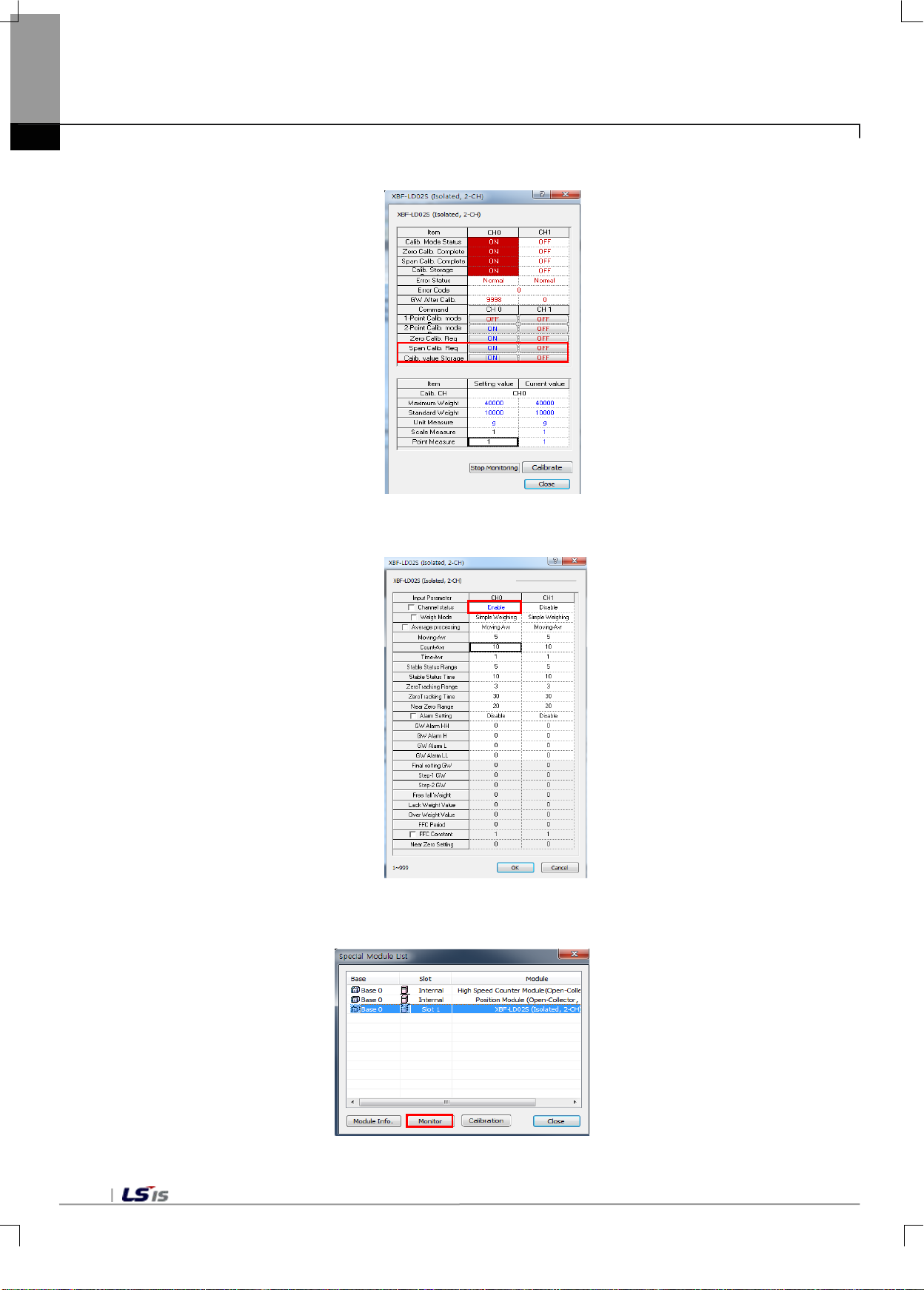
Chapter8 Programming (for XEC)
6) Place a 10kg-counterweight on the load cell, perform span calibration request, and then store the
gross weight value after calibration.
7) From the I/O Param eter on the project window, select the load cell input m odule, change C hannel 1 to
running status, and then execute writing..
8) Change the PLC to RUN status, se lect the loa d cell input m odule on the sp ecial module m onitor, and
then execute monitoring.
8-4
 Loading...