

Page 1

L80225 10/100 MbpsTX/10BT
Ethernet Physical Layer Device
(PHY)
Technical Manual
Features
®
• Single Chip 100Base-TX /10Base-T
physical layer solution
• Dual Speed - 10/100 Mbps
• Half and Full Duplex
• MII interface to Ethernet Controller
• MI interface for configuration & status
• Optional Repeater Interface
• AutoNegotiation: 10/100, Full/Half
Duplex
• Meets all applicable IEEE 802.3
standards
• Advertisement control through pins
• Adaptive Equalizer
Description - - - - - - - - - - - - - - - - - - - - - 2
Pin Description - - - - - - - - - - - - - - - - - - 4
• On-chip wave shaping - no external filters
required
• Baseline Wander Correction
• LED outputs
– Link
– Activity
– Collision
– Full Duplex
– 10/100
• Few external components
• 3.3 V supply with 5 V tolerant I/O
• 44 PLCC
Contents
Application Information - - - - - - - - - - - - 51
Specifications - - - - - - - - - - - - - - - - - - - 65
Block Diagram- - - - - - - - - - - - - - - - - - - 8
Functional Description - - - - - - - - - - - - - 9
Register Description- - - - - - - - - - - - - - -43
Note: Check for the latest revision of this document before start-
ing any designs. This document is available on the Web, at
www.lsilogic.com
MD400182/B April, 2002 1 of 88
Copyright © 1999-2002 by LSI Logic Corporation. All rights reserved.
Ordering Information - - - - - - - - - - - - - - 84
Revision History - - - - - - - - - - - - - - - - - 84
Surface Mount Packages- - - - - - - - - - - 87
Page 2

Description
The L80225 is a highly integrated analog interface IC for twisted pair
Ethernet applications. The L80225 can be configured for either
(100Base-TX) or 10 Mbps (10Base- T) Ethernet operation.
The L80225 consists of 4B5B/Manchester encoder/decoder,
scrambler/descrambler, transmitter with wave shaping and output driver,
twisted pair receiver with on chip equalizer and baseline wander
correction, clock and data recovery, AutoNegotiation, controller interface
(MII), and serial port (MI).
The addition of internal output waveshaping circuitry and on-chip filters
eliminates the need for external filters normally required in 100Base-TX
and 10Base-T applications.
The L80225 can automatically configure itself for 100 or 10 Mbps and
Full or Half Duplex operation with the on-chip AutoNegotiation algorithm.
The L80225 can access six 16-bit registers though the Management
Interface (MI) serial port. These registers contain configuration inputs,
status outputs, and device capabilities.
The L80225 is ideal as a media interface for 100Base-TX/ 10Base-T
adapter cards, motherboards, repeaters, switching hubs, and external
PHYs.
The L80225 operates from a single 3.3V supply. All inputs and outputs
are 5V tolerant and will directly interface to other 5V devices.
2 of 88 L80225 10/100 Mbps Ethernet Physical Layer Device - Technical Manual
April, 2002 Copyright © 1999-2002 by LSI Logic Corporation. All rights reserved.
Page 3
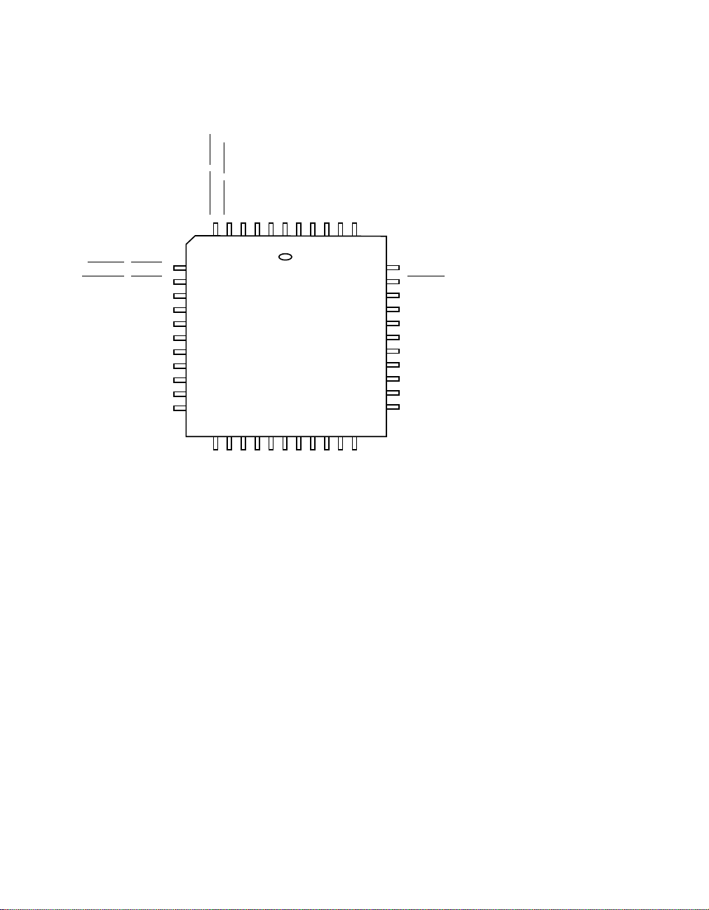
Pin Configuration
FD_LED/(MDA1)
L_LED/(MDA0)
GND2
TPI-
TPI+
VDD1
TPO-
TPO+
DUPLX
GND1
ANEG
C_LED/(MDA2)
LA_LED/(MDA3)
GND3
VDD2
SPEED
MDC
MDIO
COL
CRS
RX_DV
RX_ER
7
8
9
10
11
12
13
14
15
16
17
65432
L80225
44 Pin PLCC
Top View
21
20
19
18
RXD3
RXD2
RXD1
RXD0
1
4443424140
24
23
22
RPTR
GND5
25
VDD3
RX_CLK
27
26
GND6
RX_EN
39
38
37
36
35
34
33
32
31
30
29
28
VDD4
REXT
RESET
OSCIN
GND4
TX_EN
TX_ER
TXD3
TXD2
TXD1
TXD0
TX_CLK
April, 2002 Copyright © 1999-2002 by LSI Logic Corporation. All rights reserved.
Description 3 of 88
Page 4

1 Pin Description
Pin Description
Pin #
28
24
10
1
27
22
36
9
4
41
43 TPO+ O Twisted Pair Transmit Output, Positive.
44 TPO - O Twisted Pair Transmit Output, Negative.
2 TPI+ I Twisted Pair Receive Input, Positive.
3 TPI - I Twisted Pair Receive Input, Negative.
39 REXT — Transmit Current Set. An external resistor connected between this pin
37 OSCIN I Clock Oscillator Input. There must be either a 25 MHz crystal between
Pin
Name I/O Description
VDD4
VDD3
VDD2
VDD1
GND6
GND5
GND4
GND3
GND2
GND1
— Positive Supply. 3.3 V ± 5% Volts
— Ground. 0V
and GND will set the output current for the TP and FX transmit outputs.
this pin and GND or a 25 MHz clock applied to this pin. TX_CLK output
is generated from this input.
29 TX_CLK O Transmit Clock Output. This controller interface output provides a clock
35 TX_EN I Transmit Enable Input. This controller interface input has to be asserted
33
32
31
30
34 TX_ER I Transmit Error Input. This controller interface input causes a special pat-
4 of 88 L80225 10/100 Mbps Ethernet Physical Layer Device - Technical Manual
April, 2002 Copyright © 1999-2002 by LSI Logic Corporation. All rights reserved.
TXD3
TXD2
TXD1
TXD0
to an external controller. Transmitdatafrom the controller on TXD, TX_EN,
and TX_ER is clocked in on rising edges of TX_CLK and OSCIN.
active high to indicate that data on TXD and TX_ER is valid, and it is
clocked in on rising edges of TX_CLK and OSCIN.
I Transmit Data Input. These controller interface inputs contain input nibble
data to be transmitted on the TP outputs, and they are clocked in on rising
edges of TX_CLK and OSCIN when TX_EN is asserted.
tern to be transmitted on the twisted pair outputs in place of normal data,
and it is clocked in on rising edges of TX_CLK when TX_EN is asserted.
Page 5

Pin Description (Cont.)
Pin #
Name I/O Description
25 RX_CLK O Receive Clock Output. This controller interface output provides a clock
to an external controller. Receive data on RXD, RX_DV, and RX_ER is
clocked out on falling edges of RX_CLK.
15 CRS O Carrier Sense Output. This controller interface output is asserted active
high when valid data is detected on the receive twisted pair inputs, and it
is clocked out on falling edges of RX_CLK.
16 RX_DV O Receive Data Valid Output. This controller interface output is asserted
active high when valid decoded data is present on the RXD outputs, and
it is clocked out on falling edges of RX_CLK.
Pin
18
19
20
21
RXD3
RXD2
RXD1
RXD0
O Receive Data Output. These controller interface outputs contain receive
nibble data from the TP input, and they are clocked out on falling edges
of RX_CLK.
17 RX_ER O Receive Error Output. This controller interface output is asserted active
high when a coding or other specified errors are detected on the receive
twisted pair inputs and it is clocked out on falling edges of RX_CLK.
14 COL O Collision Output. This controller interface output is asserted active high
when a collision between transmit and receive data is detected.
12 MDC I Management Interface (MI) Clock Input. This MI clock shifts serial data
into and out of MDIO on rising edges.
13 MDIO I/O Management Interface (MI) Data Input/Output. This bidirectional pin
contains serial MI data that is clocked in and out on rising edges of the
MDC clock.
8
LA_LED/
(
MDA3)
Pullup
Link + Activity LED/Management Interface Address Input. This pin
I/O
indicates the occurrence of Link or Activity. It can drive an LED from VDD.
O.D.
0 = Link Detect
Blink = Link Detect and Activity
1 = No Link Detect
During powerup or reset, this pin is high impedance and its value is
latched in as the physical device address
7
C_LED/
(
MDA2)
I/O
O.D.
Pullup
Collision LED Output/Management Interface Address Input. This pin
indicates the occurrence of a Collision. It can drive an LED from VDD.
0 = Collision Detect
MDA3 for the MI serial port.
1 = No Collision
During powerup or reset, this pin is high impedance and the value on this
pin is latched in as the physical device address
MDA2 for the MI serial
port.
Pin Description 5 of 88
April, 2002 Copyright © 1999-2002 by LSI Logic Corporation. All rights reserved.
Page 6

Pin Description (Cont.)
Pin #
Name I/O Description
6 FD_LED/
(
MDA1)
I/O
Pullup
Full Duplex LED Output/Management Interface Address Input. This
pin a Full Duplex Detect output. It can drive an LED from VDD.
0 = Full Duplex Mode Detect with Link Pass
1 = Half Duplex
During powerup or reset, this pin is high impedance and its value is
Pin
latched in as the physical address device address
MDA1 for the MI serial
port.
5
L_LED/
(
MDA0)
I/O
Pullup
Link LED Output/Management Interface Address Input. This pin is a
10/100 Mbps Detect output. It can drive an LED from VDD.
0 = 100 Mbit Mode Detected with Link Pass
1 = 10 Mbit Mode Detected
During powerup or reset, this pin is high impedance and the value on this
pin is latched in as the address
MDA0 for the MI serial port.
26 RX_EN I Receive Enable Input
1 = All Outputs Enabled
0 = Receive Controller Outputs are High Impedance (RX_CLK,
RXD[3:0], RX_DV, RX_ER, COL).
23 RPTR I Repeater Mode Enable Input.
1 = Repeater Mode Enabled
0 = Normal Operation
11 SPEED I Speed Select Input. This input pin selects 10/100 Mbps operation when
pin ANEG = 0. When ANEG = 1, this pin controls the 10/100 advertisement abilities of the device.
1 = 100 Mbps
0 = 10 Mbps
42 DPLX I Full/Half Duplex Select Input. This input pin selects Half/Full Duplex
operation when pin ANEG = 0. When ANEG = 1, this pin controls the
Half/Full Duplex advertisement abilities.
1 = Full Duplex
0 = Half Duplex
6 of 88 L80225 10/100 Mbps Ethernet Physical Layer Device - Technical Manual
April, 2002 Copyright © 1999-2002 by LSI Logic Corporation. All rights reserved.
Page 7

Pin Description (Cont.)
Pin #
Name I/O Description
40 ANEG I AutoNegotiation Enable Input.
1 = AutoNegotiation On
0 = AutoNegotiation Off
ANEG Speed Duplx
0 0 0 Forced 10 Mbit Half Duplex Mode
0 0 1 Forced 10 Mbit Full Duplex Mode
0 1 0 Forced 100 Mbit Half Duplex Mode
0 1 1 Forced 100 Mbit Full Duplex Mode
1 0 0 AutoNegotiate and Advertise 10 M Half
Duplex only
1 0 1 AutoNegotiate and Advertise 10 M Half/Full
Duplex only
1 1 0 AutoNegotiate and Advertise all the capabili-
ties Mode (Default).
Note: To control advertisement through the
register, these three pins must be configured
in this default mode.
1 1 1 AutoNegotiate and Advertise 10/100 M Half
Duplex only
Pin
38
RESET I
Pullup
RESET Input
1 = Normal Operation
0 = Device Reset
April, 2002 Copyright © 1999-2002 by LSI Logic Corporation. All rights reserved.
Pin Description 7 of 88
Page 8
April, 2002 Copyright © 1999-2002 by LSI Logic Corporation. All rights reserved.
8 of 88 L80225 10/100 Mbps Ethernet Physical Layer Device - Technical Manual
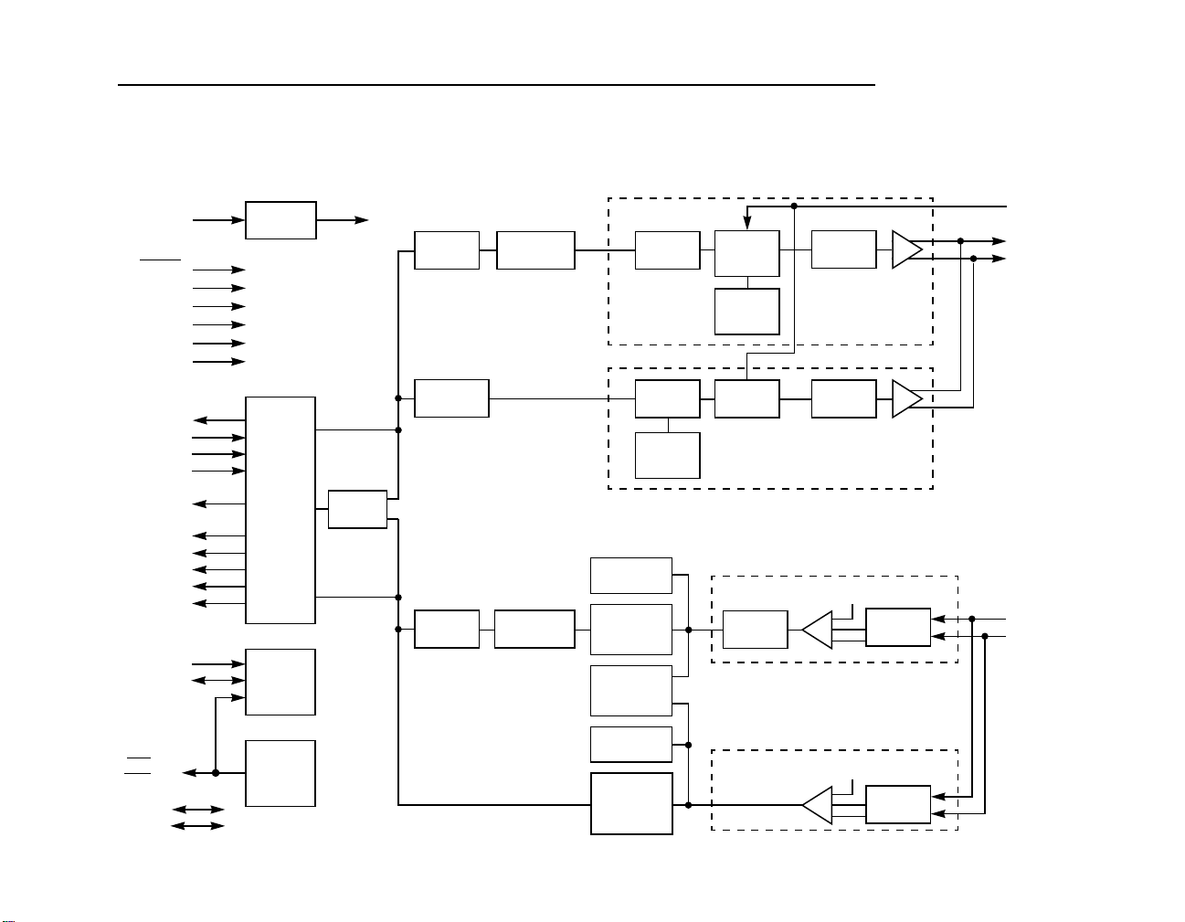
2 Block Diagram
Figure 1 Block Diagram
OSCIN
RESET
RX_EN
RPTR
ANEG
DPLX
SPEED
TX_CLK
TXD[3:0]
TX_EN
TX_ER
RX_CLK
RXD[3:0]
RX_DV
RX_ER
MDIO
LED[3:0]
MDA[3:0]
VDD[4:1]
GND[6:1]
COL
CRS
MDC
Oscillator
Controller
Interface
(MII)
Serial
Port
(MI)
LED
Drivers
Collison
4B5B
Encoder
Manchester
Encoder
4B5B
Decoder
Scrambler
Descrambler
100BASETX Transmitter
MLT3
Encoder
Generator
10BaseT Transmitter
ROM DAC
Clock
Generator
PLL
Squelch
Clock
& Data
Recovery
Auto-
Negotiation
& Link
Squelch
Clock & Data
Recovery
(Manchester
Decoder)
100BaseTX Receiver
10BaseTX Receiver
Switched
Current
Sources
Clock
PLL
MLT3
Encoder
Filter
Filter
+
+
−
+/− Vth
+
+
−
LP
LP
+/− Vth
+
-
+
−
Adaptive
Equalizer
LP
Filter
REXT
TPO+
TPO−
TPI+
TPI−
Page 9

3 Functional Description
3.1 General
The L80225 is a complete 100/10 Mbps Ethernet Media Interface IC. The
L80225 has nine main sections: controller interface, encoder, decoder,
scrambler, descrambler, clock and data recovery, twisted pair transmitter,
twisted pair receiver, and MI serial port. A block diagram is shown in
Figure 1.
The L80225 can operate as a 100Base-TX device (hereafter referred to
as 100 Mbps mode) or as a 10Base-T device (hereafter referred to as
10 Mbps mode). The difference between the 100 Mbps mode and the 10
Mbps mode is data rate, signaling protocol, and allowed wiring. The 100
Mbps TX mode uses two pairs of category 5 or better UTP or STP
twisted pair cable with 4B5B encoded, scrambled, and MLT-3 coded 62.5
MHz ternary data to achieve a throughput of 100 Mbps. The 10 Mbps
mode uses two pairs of category 3 or better UTP or STP twisted pair
cable with Manchester encoded, 10 MHz binary data to achieve a 10
Mbps throughput. The data symbol format on the twisted pair cable for
the 100 and 10 Mbps modes is defined in IEEE 802.3 specifications and
shown in Figure 2.
On the transmit side for 100 Mbps TX operation, data is received on the
controller interface from an external Ethernet controller per the format
shown in Figure 3. The data is then sent to the 4B5B encoder for
formatting. The encoded data is then sent to the scrambler. The
scrambled and encoded data is then sent to the TP transmitter. The TP
transmitter converts the encoded and scrambled data into MLT-3 ternary
format, preshapes the output, and drives the twisted pair cable.
April, 2002 Copyright © 1999-2002 by LSI Logic Corporation. All rights reserved.
Functional Description 9 of 88
Page 10
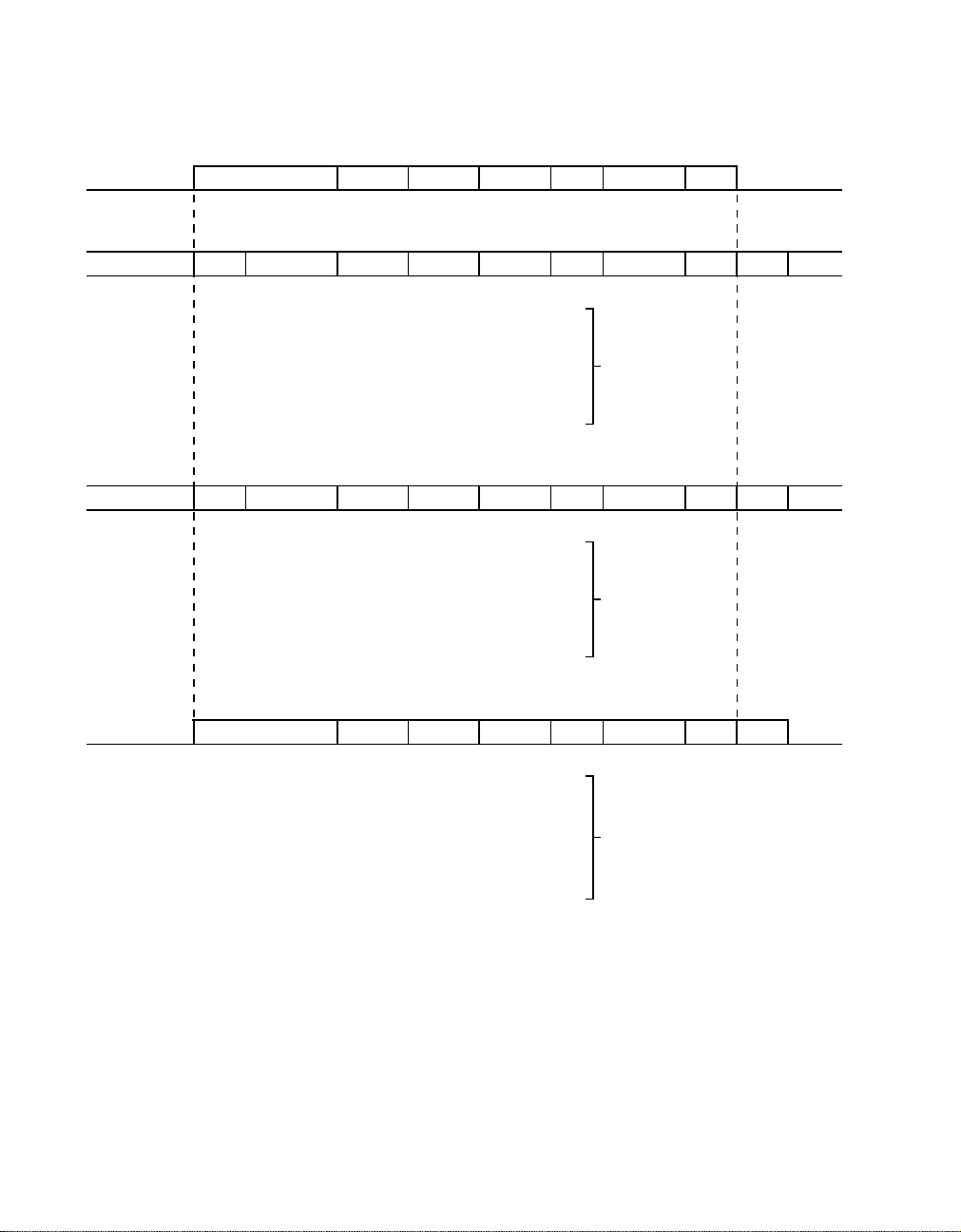
Figure 2 TX/10BT Frame Format
Interframe
GAP
IDLE PREAMBLE SFD ESD IDLE
IDLE PREAMBLE SFD ESD IDLE
PREAMBLE SFD DA SA LN
SSD DA SA LN LLC DATA FCS
PREAMBLE =
DA, SA, LN, LLC DATA, FCS =
SSD DA SA LN LLC DATA FCS
PREAMBLE =
DA, SA, LN, LLC DATA, FCS =
Ethernet MAC Frame
100 Base-TX Data Symbols
[ 1 1 1 1 ...]
IDLE =
[ 1 1 0 0 0 1 0 0 0 1 ]
SSD =
[ 1 0 1 0 ...] 62 Bits Long
[ 1 1 ]
SFD =
[ DATA ]
[ 0 1 1 0 1 0 0 1 1 1 ]
ESD =
100 Base-FX Data Symbols
[ 1 1 1 1 ...]
IDLE =
[ 1 1 0 0 0 1 0 0 0 1 ]
SSD =
[ 1 0 1 0 ...] 62 Bits Long
[ 1 1 ]
SFD =
[ DATA ]
[ 0 1 1 0 1 0 0 1 1 1 ]
ESD =
LLC Data
Before/After
4B5B Encoding,
Scrambling, and
MLT3 Coding
Before/After
4B5B Encoding
FCS
Interframe
GAP
10 Base-T Data Symbols
IDLE PREAMBLE SFD SOI IDLE
IDLE =
PREAMBLE =
SFD =
DA, SA, LN, LLC DATA, FCS =
DA SA LN LLC DATA FCS
[ NoTransitions ]
[ 1 0 1 0 ...] 62 Bits Long
[ 1 1 ]
[ DATA ]
[ 1 1 ] With No MID Bit
SOI =
Transition
Before/After
Manchester
Encoding
10 of 88 L80225 10/100 Mbps Ethernet Physical Layer Device - Technical Manual
April, 2002 Copyright © 1999-2002 by LSI Logic Corporation. All rights reserved.
Page 11
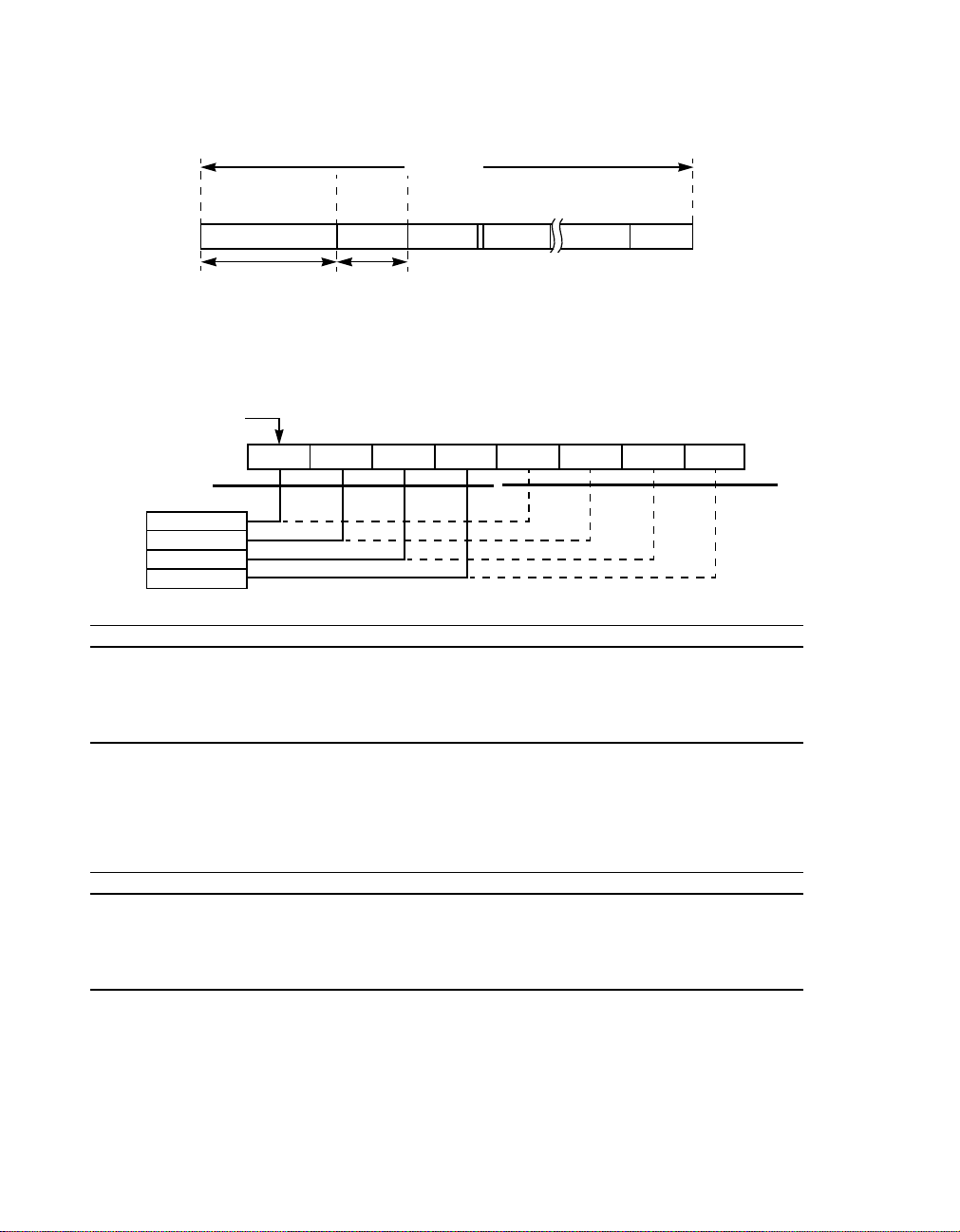
Figure 3 MII Frame Format
a. MII Frame Format
TX_EN = 0
IDLE
PREAMBLE
Start of
PRMBLE SFD DATA 1
62 Bits 2 Bits
PREAMBLE =
First Bit
LSB
D0
D1 D2 D3 D4
First
Nibble
TXD0/RXD0
MII
Nibble
Stream
TXD1/RXD1
TXD2/RXD2
TXD3/RXD3
c. Transmit Preamble and SFD Bits
Signals
TXD0 X
TXD1
TXD2
TXD3
TX_EN
X
X
X
0
1
X
1
1
1
X
0
X
X
0
0
1
1
0
0
1
1
1
0
0
1
1
0
0
1
1
1. 1st preamble nibble transmitted.
2. 1st SFD nibble transmitted.
3. 1st data nibble transmitted.
4. D0 thru D7 are the first 8 bits of the data field.
TX_EN = 1
Frame
Delim.
SFD =
DATAn =
IDLE =
b. MII Nibble Order
MACs Serial Bit Stream
1
1
0
0
1
1
0
0
1
1
DATA Nibbles
DATA 2 DATA N-1 DATA N
[ 1 0 1 0 ...] 62 Bits Long
[ 1 1 ]
[Between 64−1518 Data Bytes]
TX_EN = 0
D5 D6 D7
Bit Value
1
1
1
1
1
1
0
0
0
0
1
1
0
1
1
0
0
1
1
0
1
1
0
0
1
1
1
0
0
1
1
0
0
1
1
TX_EN = 0
IDLE
MSB
Second
Nibble
2
1
1
0
0
1
1
0
0
1
1
3
1
D0
0
D1
1
D2
1
D3
1
1
D4
D5
D6
D7
1
3
d. Receive Preamble and SFD Bits
Signals
RXD0 X
RXD1
RXD2
RXD3
RX_DV
1
1
1
1
1
1
1
X
0
0
0
0
X
1
1
X
0
0
1
1
0
0
1
1
0
1
1
0
0
1
1
1
0
0
1
1
0
0
1
1
1
0
1
0
1
Bit Value
1
1
0
0
1
1
0
0
1
1
1
1
1
0
0
1
1
0
0
1
1
1
0
0
1
1
0
0
1
1
2
1
1
0
0
1
1
0
0
1
1
3
1
D0
0
D1
1
D2
1
D3
1
1
D4
D5
D6
D7
1
3
1. 1st preamble nibble received. Depending on mode, device may eliminate either all or some of the preamble
nibbles, up to 1st SFD nibble.
2. 1st SFD nibble received.
3. 1st data nibble received.
4. D0 thru D7 are the first 8 bits of the data field.
Functional Description 11 of 88
April, 2002 Copyright © 1999-2002 by LSI Logic Corporation. All rights reserved.
Page 12

On the receive side for 100 Mbps TX operation, the twisted pair receiver
receives incoming encoded and scrambled MLT-3 data from the twisted
pair cable, removes any high frequency noise, equalizes the input signal
to compensate for the effects of the cable, qualifies the data with a
squelch algorithm, and converts the data from MLT-3 coded twisted pair
levelsto internal digital levels. The output of the twisted pair receiver then
goes to a clock and data recovery block which recovers a clock from the
incoming data, uses the clock to latch in valid data into the device, and
converts the data back to NRZ format. The NRZ data is then
unscrambled and decoded by the 4B5B decoder and descrambler,
respectively, and outputted to an external Ethernet controller by the
controller interface.
10 Mbps operation is similar to the 100 Mbps TX operation except, (1)
there is no scrambler/descrambler, (2) the encoder/decoder is
Manchester instead of 4B5B, (3) the data rate is 10 Mbps instead of 100
Mbps, and (4) the twisted pair symbol data is two level Manchester
instead of ternary MLT-3.
The Management Interface, (hereafter referred to as the MI serial port),
is a two pin bidirectional link through which configuration inputs can be
set and status outputs can be read.
Each block plus the operating modes are described in more detail in the
following sections. Since the L80225 can operate as either a 100BaseTX or a 10Base-T device, each of the following sections describes the
performance of the respective section in both the 100 and 10 Mbps
modes.
12 of 88 L80225 10/100 Mbps Ethernet Physical Layer Device - Technical Manual
April, 2002 Copyright © 1999-2002 by LSI Logic Corporation. All rights reserved.
Page 13

3.2 Differences between 80220/80221, L80225, and 80223
Table 1 80221, L80225, and 80223
Difference 80221 L80225 80223
Power Supply 5V 3.3V 3.3V
RESET Pin No Yes Yes
FX Interface No Yes Yes
Transmit Xfmr. Winding Ratio 2:1 1:1 1:1
T4 Interface Yes No No
Speed Pin No Yes Yes
Duplx Pin No Yes Yes
Hardware Advertisement Control No Yes No
Registers 16-20 Yes No Yes
3.3 Controller Interface
3.3.1 General
The L80225 has two interfaces to an external controller: Media
Independent Interface (referred to as the MII).
3.3.2 MII - 100 Mbps
The MII is a nibble wide packet data interface defined in IEEE 802.3 and
shown in Figure 3. The L80225 meets all the MII requirements outlined
in IEEE 802.3. The L80225 can directly connect, without any external
logic, to any Ethernet controllers or other devices which also complies
with the IEEE 802.3 MII specifications. The MII frame format is shown in
Figure 3.
The MII consists of eighteen signals: four transmit data bits (TXD[3:0]),
transmit clock (TX_CLK), transmit enable (TX_EN), transmit error
(TX_ER), four receive data bits (RXD[3:0]), receive clock (RX_CLK),
carrier sense (CRS), receive data valid (RX_DV), receive data error
April, 2002 Copyright © 1999-2002 by LSI Logic Corporation. All rights reserved.
Functional Description 13 of 88
Page 14

(RX_ER), and collision (COL). The transmit and receive clocks operate
at 25 MHz in 100 Mbps mode.
On the transmit side, the TX_CLK output runs continuously at 25 MHz.
When no data is to be transmitted, TX_EN has to be deasserted. While
TX_EN is deasserted, TX_ER and TXD[3:0] are ignored and no data is
clocked into the device. When TX_EN is asserted on the rising edge of
TX_CLK, data on TXD[3:0] is clocked into the device on rising edges of
the TX_CLK output clock. TXD[3:0] input data is nibble wide packet data
whose format needs to be the same as specified in IEEE 802.3 and
shown in Figure 3. When all data on TXD[3:0] has been latched into the
device, TX_EN has to be deasserted on the rising edge of TX_CLK.
TX_ER is also clocked in on rising edges of the TX_CLK clock. TX_ER
is a transmit error signal which, when asserted, will substitute an error
nibble in place of the normal data nibble that was clocked in on TXD[3:0].
The error nibble is defined to be the /H/ symbol, which is defined in IEEE
802.3 and shown in Table 2.
Since OSCIN input clock generates the TX_CLK output clock, TXD[3:0],
TX_EN, and TX_ER are also clocked in on rising edges of OSCIN.
On the receive side, as long as a valid data packet is not detected, CRS
and RX_DV are deasserted and RXD[3:0] is held low. When the start of
packet is detected, CRS and RX_DV are asserted on falling edge of
RX_CLK. The assertion of RX_DV indicates that valid data is clocked out
on RXD[3:0] on falling edges of the RX_CLK clock. The RXD[3:0] data
has the same frame structure as the TXD[3:0] data and is specified in
IEEE 802.3 and shown in Figure 3. When the end of packet is detected,
CRS and RX_DV are deasserted, and RXD[3:0] is held low. CRS and
RX_DV also stay deasserted if the device is in the Link Fail State.
RX_ER is a receive error output which is asserted when certain errors
are detected on a data nibble. RX_ER is asserted on the falling edge of
RX_CLK for the duration of that RX_CLK clock cycle during which the
nibble containing the error is being outputted on RXD[3:0].
The collision output, COL, is asserted whenever the collision condition is
detected.
14 of 88 L80225 10/100 Mbps Ethernet Physical Layer Device - Technical Manual
April, 2002 Copyright © 1999-2002 by LSI Logic Corporation. All rights reserved.
Page 15

3.3.3 MII - 10 Mbps
3.3.4 MII Disable
10 Mbps operation is identical to the 100 Mbps operation except, (1)
TX_CLK and RX_CLK clock frequency is reduced to 2.5 MHZ, (2)
TX_ER is ignored, (3) RX_ER is disabled and always held low, and (4)
receive operation is modified as follows: On the receive side, when the
squelch circuit determines that invalid data is present on the TP inputs,
the receiver is idle. During idle, RX_CLK follows TX_CLK, RXD[3:0] is
held low, and CRS and RX_DV are deasserted. When a start of packet
is detected on the TP receive inputs, CRS is asserted and the clock
recovery process starts on the incoming TP input data. After the receive
clock has been recovered from the data, the RX_CLK is switched over
to the recovered clock and the data valid signal RX_DV is asserted on a
falling edge of RX_CLK. Once RX_DV is asserted, valid data is clocked
out on RXD[3:0] on falling edges of the RX_CLK clock. The RXD[3:0]
data has the same packet structure as the TXD[3:0] data and is
formatted on RXD[3:0] as specified in IEEE 802.3 and shown in Figure 3.
When the end of packet is detected, CRS and RX_DV are deasserted.
CRS and RX_DV also stay deasserted as long as the device is in the
Link Fail State.
The MII inputs and outputs can be disabled by setting the MII disable bit
in the MI serial port Control register. When the MII is disabled, the MII
inputs are ignored, the MII outputs are placed in high impedance state,
and the TP output is high impedance.
If the MI address lines, MDA[3:0], are pulled high during reset or
powerup, the L80225 powers up and resets with the MII disabled.
Otherwise, the L80225 powers up and resets with the MII enabled.
3.3.5 Receive Output High Impedance Control
The RX_EN pin can be configured to be RX_EN, a high impedance
control for the receive controller output signals, by setting the R/J
Configuration select bit in the MI serial port Configuration 2 register.
When this pin is configured to be RX_EN and is deasserted active low,
the following outputs will be placed in the high impedance state:
RX_CLK, RXD[3:0], RX_DV, RX_ER, and COL.
April, 2002 Copyright © 1999-2002 by LSI Logic Corporation. All rights reserved.
Functional Description 15 of 88
Page 16

3.3.6 TX_EN to CRS Loopback Disable
The internal TX_EN to CRS loopback can be disabled by appropriately
setting the TXEN to CRS loopback disable bit in the MI serial port
Configuration 1 register.
3.4 Encoder
3.4.1 4B5B Encoder - 100 Mbps
100Base-TX requires that the data be 4B5B encoded. 4B5B coding
converts the 4-Bit data nibbles into 5-Bit date code words. The mapping
of the 4B nibbles to the 5B code words is specified in IEEE 802.3 and
shown in Table 2. The 4B5B encoder on the L80225 takes 4B nibbles
from the controller interface, converts them into 5B words according to
Table 2, and sends the 5B words to the scrambler. The 4B5B encoder
also substitutes the first 8 bits of the preamble with the SSD delimiters
(a.k.a. /J/K/ symbols) and adds an ESD delimiter (a.k.a. /T/R/ symbols)
to the end of every packet, as defined in IEEE 802.3 and shown in
Figure 2. The 4B5B encoder also fills the period between packets, called
the idle period, with the a continuous stream of idle symbols, as shown
in Figure 2.
3.4.2 Manchester Encoder - 10 Mbps
The Manchester encoding process combines clock and NRZ data such
that the first half of the data bit contains the complement of the data, and
the second half of the data bit contains the true data, as specified in
IEEE 802.3. This guarantees that a transition always occurs in the middle
of the bit cell. The Manchester encoder on the L80225 converts the 10
Mbps NRZ data from the controller interface into a Manchester Encoded
data stream for the TP transmitter and adds a start of idle pulse (SOI) at
the end of the packet as specified in IEEE 802.3 and shown in Figure 2.
The Manchester encoding process is only done on actual packet data,
16 of 88 L80225 10/100 Mbps Ethernet Physical Layer Device - Technical Manual
April, 2002 Copyright © 1999-2002 by LSI Logic Corporation. All rights reserved.
Page 17

and the idle period between packets is not Manchester encoded and
filled with link pulses.
Table 2 4B/5B Symbol Mapping
Symbol Name Description 5B Code 4B Code
0 Data 0 11110 0000
1 Data 1 01001 0001
2 Data 2 10100 0010
3 Data 3 10101 0011
4 Data 4 01010 0100
5 Data 5 01011 0101
6 Data 6 01110 0110
7 Data 7 01111 0111
8 Data 8 10010 1000
9 Data 9 10011 1001
A Data A 10110 1010
B Data B 10111 1011
C Data C 11010 1100
D Data D 11011 1101
E Data E 11100 1110
F Data F 11101 1111
I Idle 11111 0000
J SSD #1 11000 0101
K SSD #2 10001 0101
T ESD #1 01101 0000
R ESD #2 00111 0000
April, 2002 Copyright © 1999-2002 by LSI Logic Corporation. All rights reserved.
Functional Description 17 of 88
Page 18

Table 2 4B/5B Symbol Mapping (Cont.)
Symbol Name Description 5B Code 4B Code
H Halt 00100 Undefined
--- Invalid codes All others
1. These 5B codes are not used. For decoder, these 5B codes are
decoded to 4B 0000. For encoder, 4B 0000 is encoded to 5B
11110, as shown in symbol Data 0.
3.5 Decoder
3.5.1 4B5B Decoder - 100 Mbps
Since the TP input data is 4B5B encoded on the transmit side, it must
also be decoded by the 4B5B decoder on the receive side. The mapping
of the 5B nibbles to the 4B code words is specified in IEEE 802.3 and
shown in Table 2. The 4B45 decoder on the L80225 takes the 5B code
words from the descrambler, converts them into 4B nibbles per Table 2,
and sends the 4B nibbles to the controller interface. The 4B5B decoder
also strips off the SSD delimiter (a.k.a. /J/K/ symbols) and replaces them
with two 4B Data 5 nibbles (a.k.a. /5/ symbol), and strips off the ESD
delimiter (a.k.a. /T/R/ symbols) and replaces it with two 4B Data 0 nibbles
(a.k.a. /I/ symbol), per IEEE 802.3 specifications and shown in Figure 2.
The 4B5B decoder detects SSD, ESD and, codeword errors in the
incoming data stream as specified in IEEE 802.3. These errors are
indicated by asserting RX_ER output while the errors are being
transmitted across RXD[3:0], and they are also indicated in the serial
port by setting SSD, ESD, and codeword error bits in the MI serial port
Status Output register.
1
0000
1
3.5.2 Manchester Decoder - 10 Mbps
In Manchester coded data, the first half of the data bit contains the
complement of the data, and the second half of the data bit contains the
true data. The Manchester decoder in the L80225 converts the
Manchester encoded data stream from the TP receiver into NRZ data for
the controller interface by decoding the data and stripping off the SOI
18 of 88 L80225 10/100 Mbps Ethernet Physical Layer Device - Technical Manual
April, 2002 Copyright © 1999-2002 by LSI Logic Corporation. All rights reserved.
Page 19

pulse. Since the clock and data recovery block has already separated the
clock and data from the TP receiver, the Manchester decoding process
to NRZ data is inherently performed by that block.
3.6 Clock and Data Recovery
3.6.1 Clock Recovery - 100 Mbps
Clock recovery is done with a PLL. If there is no valid data present on
the TP inputs, the PLL is locked to the 25 MHz TX_CLK. When valid data
is detected on the TP inputs with the squelch circuit and when the
adaptive equalizer has settled, the PLL input is switched to the incoming
data on the TP input. The PLL then recovers a clock by locking onto the
transitions of the incoming signal from the twisted pair wire. The
recovered clock frequency is a 25 MHz nibble clock, and that clock is
outputted on the controller interface signal RX_CLK.
3.6.2 Data Recovery - 100 Mbps
Data recovery is performed by latching in data from the TP receiver with
the recovered clock extracted by the PLL. The data is then converted
from a single bit stream into nibble wide data word according to the
format shown in Figure 3.
3.6.3 Clock Recovery - 10 Mbps
The clock recovery process for 10 Mbps mode is identical to the 100
Mbps mode except, (1) the recovered clock frequency is 2.5 MHz nibble
clock, (2) the PLL is switched from TX_CLK to the TP input when the
squelch indicates valid data, (3) The PLL takes up to 12 transitions (bit
times) to lock onto the preamble, so some of the preamble data symbols
are lost, but the clock recovery block recovers enough preamble symbols
to pass at least 6 nibbles of preamble to the receive controller interface
as shown in Figure 3.
3.6.4 Data Recovery - 10 Mbps
The data recovery process for 10 Mbps mode is identical to the 100
Mbps mode. As mentioned in the Manchester Decoder section, the data
recovery process inherently performs decoding of Manchester encoded
data from the TP inputs.
April, 2002 Copyright © 1999-2002 by LSI Logic Corporation. All rights reserved.
Functional Description 19 of 88
Page 20

3.7 Scrambler
3.7.1 100 Mbps
3.7.2 10 Mbps
3.8 Descrambler
3.8.1 100 Mbps
100Base-TX requires scrambling to reduce the radiated emissions on the
twisted pair. The L80225 scrambler takes the encoded data from the
4B5B encoder, scrambles it per the IEEE 802.3 specifications, and sends
it to the TP transmitter.
A scrambler is not used in 10 Mbps mode.
The L80225 descrambler takes the scrambled data from the data
recovery block, descrambles it per the IEEE 802.3 specifications, aligns
the data on the correct 5B word boundaries, and sends it to the 4B5B
decoder.
The algorithm for synchronization of the descrambler is the same as the
algorithm outlined in the IEEE 802.3 specification. Once the descrambler
is synchronized, it will maintain synchronization as long as enough
descrambled idle pattern 1's are detected within a given interval. To stay
in synchronization, the descrambler needs to detect at least 25
consecutive descrambled idle pattern 1's in a 1 ms interval. If 25
consecutive descrambled idle pattern 1's are not detected within the 1
ms interval, the descrambler goes out of synchronization and restarts the
synchronization process.
If the descrambler is in the unsynchronized state, the descrambler loss
of synchronization detect bit is set in the MI serial port Status Output
register to indicate this condition. Once this bit is set, it will stay set until
the descrambler achieves synchronization.
3.8.2 10 Mbps
A descrambler is not used in 10 Mbps mode.
20 of 88 L80225 10/100 Mbps Ethernet Physical Layer Device - Technical Manual
April, 2002 Copyright © 1999-2002 by LSI Logic Corporation. All rights reserved.
Page 21

3.9 Twisted Pair Transmitter
3.9.1 Transmitter - 100 Mbps
The TX transmitter consists of an MLT-3 encoder, waveform generator,
and line driver.
The MLT-3 encoder converts the NRZ data from the scrambler into a
three level MLT-3 code required by IEEE 802.3. MLT-3 coding uses three
levels and converts 1's to transitions between the three levels, and
converts 0's to no transitions or changes in level.
The purpose of the waveform generator is to shape the transmit output
pulse. The waveform generator takes the MLT-3 three level encoded
waveform and uses an array of switched current sources to control the
rise/fall time and level of the signal at the output. The output of the
switched current sources then goes through a low pass filter in order to
"smooth" the current output and removeany high frequency components.
In this way, the waveform generator preshapes the output waveform
transmitted onto the twisted pair cable to meet the pulse template
requirements outlined in IEEE 802.3. The waveform generator eliminates
the need for any external filters on the TP transmit output.
The line driver converts the shaped and smoothed waveform to a current
output that can drive 100 meters of category 5 unshielded twisted pair
cable or 150 Ohm shielded twisted pair cable.
3.9.2 Transmitter - 10 Mbps
The transmitter operation in 10 Mbps mode is much different from the
100 Mbps transmitter. Even so, the transmitter still consists of a
waveform generator and line driver.
The purpose of the waveform generator is to shape the output transmit
pulse. The waveform generator consists of a ROM, DAC, clock generator,
and filter. The DAC generates a stair-stepped representation of the
desired output waveform. The stairstepped DAC output then goes
through a low pass filter in order to "smooth" the DAC output and remove
any high frequency components. The DAC values are determined from
the ROM outputs; the ROM contents are chosen to shape the pulse to
the desired template and are clocked into the DAC at high speed by the
clock generator. In this way, the waveform generator preshapes the
April, 2002 Copyright © 1999-2002 by LSI Logic Corporation. All rights reserved.
Functional Description 21 of 88
Page 22

output waveform to be transmitted onto the twisted pair cable to meet the
pulse template requirements outlined in IEEE 802.3 Clause 14 and also
shown in Figure 4. The waveshaper replaces and eliminates external
filters on the TP transmit output.
The line driver converts the shaped and smoothed waveform to a current
output that can drive 100 meters of category 3/4/5 100 Ohm unshielded
twisted pair cable or 150 Ohm shielded twisted pair cable tied directly to
the TP output pins without any external filters. During the idle period, no
output signal is transmitted on the TP outputs (except link pulse).
3.9.3 STP (150 Ohm) Cable Mode
The transmitter can be configured to drive 150 Ohm shielded twisted pair
cable. The STP mode can be selected by appropriately setting the cable
type select bit in the MI serial port Configuration 1 register. When STP
mode is enabled, the output current is automatically adjusted to comply
with IEEE 802.3 levels.
3.9.4 Activity Indication
The
LA_LED indicates the combination of link detect and activity. Link
detect 10 or 100 MB causes this LED to stay ON and the detection of
activity causes the LED to blink whenever activity is detected. The LED
goes low for 100 ms every time a transmit or receive packet activity is
detected.
The LA_LED output is an open drain with a pullup resistor and can drive
an LED from VDD or can drive another digital input.
3.10 Twisted Pair Receiver
3.10.1 Receiver - 100 Mbps
The TX receiver detects input signals from the twisted pair input and
converts it to a digital data bit stream ready for clock and data recovery.
The receiver can reliably detect data from a 100Base-TX compliant
transmitter that has been passed through 0-100 meters of 100 Ohm
category 5 UTP or 150 Ohm STP.
The TX receiver consists of an adaptive equalizer, baseline wander
correction circuit, comparators, and MLT-3 decoder. The TP inputs first
22 of 88 L80225 10/100 Mbps Ethernet Physical Layer Device - Technical Manual
April, 2002 Copyright © 1999-2002 by LSI Logic Corporation. All rights reserved.
Page 23

go to an adaptive equalizer. The adaptive equalizer compensates for the
low pass characteristic of the cable, and it has the ability to adapt and
compensate for 0-100 meters of category 5,100 Ohm UTP or 150 Ohm
STP twisted pair cable. The baseline wander correction circuit restores
the DC component of the input waveform that was removed by external
transformers. The comparators convert the equalized signal back to
digital levels and are used to qualify the data with the squelch circuit. The
MLT-3 decoder takes the three level MLT-3 digital data from the
comparators and converts it to back to normal digital data to be used for
clock and data recovery.
3.10.2 Receiver - 10 Mbps
The 10 Mbps receiver is able to detect input signals from the twisted pair
cable that are within the template shown in Figure 5. The inputs are
biased by internal resistors. The TP inputs pass through a low pass filter
designed to eliminate any high frequency noise on the input. The output
of the receive filter goes to two different types of comparators, squelch
and zero crossing. The squelch comparator determines whether the
signal is valid, and the zero crossing comparator is used to sense the
actual data transitions once the signal is determined to be valid. The
output of the squelch comparator goes to the squelch circuit and is also
used for link pulse detection, SOI detection, and reverse polarity
detection; the output of the zero crossing comparator is used for clock
and data recovery in the Manchester decoder.
3.10.3 TP Squelch - 100 Mbps
The squelch block determines if the TP input contains valid data. The
100 Mbps TP squelch is one of the criteria used to determine link
integrity. The squelch comparators compare the TP inputs against fixed
positive and negative thresholds, called squelch levels.
April, 2002 Copyright © 1999-2002 by LSI Logic Corporation. All rights reserved.
Functional Description 23 of 88
Page 24
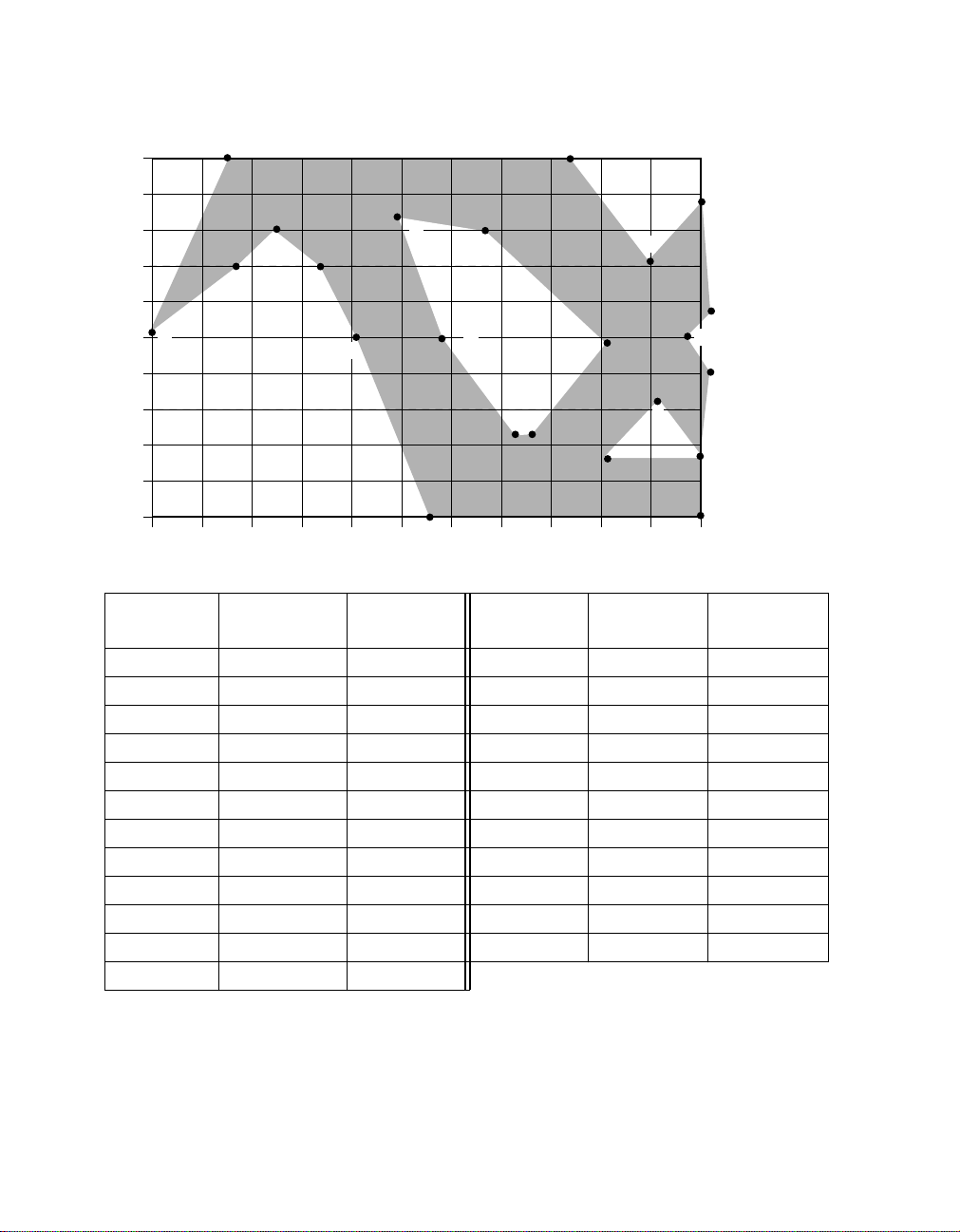
Figure 4 TP Output Voltage Template-10 Mbps
1.0
0.8
0.6
0.4
0.2
0.0
A
Voltage (V)
- 0.2
- 0.4
- 0.6
- 0.8
- 1.0
0102030405060708090100110
B
D
C
E
F
H
G
Time (ns)
I
M
Time (ns)
Reference
Internal MAU Voltage (V) Reference
N
J
K
L
W
Time (ns)
Internal MAU Voltage (V)
A 0 0 M 61 0
B 15 1.0 N 85 1.0
C 15 0.4 O 100 0.4
D 25 0.55 P 110 0.75
E 32 0.45 Q 111 0.15
F 39 0 R 111 0
G 57 -1.0 S 111 -0.15
H 48 0.7 T 110 -1.0
I 67 0.6 U 100 -0.3
J 89 0 V 110 -0.7
K 74 -0.55 W 90 -0.7
L 73 -0.55
P
O
Q
R
S
U
V
T
The output from the squelch comparator goes to a digital squelch circuit
which determines if the receive input data on that channel is valid. If the
data is invalid, the receiver is in the squelched state. If the input voltage
24 of 88 L80225 10/100 Mbps Ethernet Physical Layer Device - Technical Manual
April, 2002 Copyright © 1999-2002 by LSI Logic Corporation. All rights reserved.
Page 25

exceeds the squelch levels at least 4 times with alternating polarity within
a 10 mS interval, the data is considered to be valid by the squelch circuit
and the receiver now enters into the unsquelch state. In the unsquelch
state, the receive threshold level is reduced by approximately 30% for
noise immunity reasons and is called the unsquelch level. When the
receiver is in the unsquelch state, then the input signal is deemed to be
valid. The device stays in the unsquelch state until loss of data is
detected. Loss of data is detected if no alternating polarity unsquelch
transitions are detected during any 10 mS interval. When the loss of data
is detected, the receive squelch is turned on again.
3.10.4 TP Squelch, 10 Mbps
The TP squelch algorithm for 10 Mbps mode is identical to the 100 Mbps
mode except, (1) the 10 Mbps TP squelch algorithm is not used for link
integrity but to sense the beginning of a packet, (2) the receiver goes into
the unsquelch state if the input voltage exceeds the squelch levels for
three bit times with alternating polarity within a 50-250 ns interval, (3) the
receiver goes into the squelch state when idle is detected, (4) unsquelch
detection has no affect on link integrity, link pulses are used for that in
10 Mbps mode, (5) start of packet is determined when the receiver goes
into the unsquelch state and CRS is asserted, and (6) the receiver meets
the squelch requirements defined in IEEE 802.3 Clause 14.
3.11 Collision
3.11.1 100 Mbps
Collision occurs whenever transmit and receive occur simultaneously
while the device is in Half Duplex.
Collision is sensed whenever there is simultaneous transmission (packet
transmission on TPO±) and reception (non idle symbols detected on TP
input). When collision is detected, the COL output is asserted, TP data
continues to be transmitted on twisted pair outputs, TP data continues to
be received on twisted pair inputs, and internal CRS loopback is
disabled. Once collision starts, CRS is asserted and stays asserted until
the receive and transmit packets that caused the collision are terminated.
The collision function is disabled if the device is in the Full Duplex mode
or is in the Link Fail state, or if the device is in the diagnostic loopback
mode.
April, 2002 Copyright © 1999-2002 by LSI Logic Corporation. All rights reserved.
Functional Description 25 of 88
Page 26

3.11.2 10 Mbps
Collision in 10 Mbps mode is identical to the 100 Mbps mode except, (1)
reception is determined by the 10 Mbps squelch criteria, (2) RXD[3:0]
outputs are forced to all 0's, (3) collision is asserted when the SQE test
is performed, (4) collision is asserted when the jabber condition has been
detected.
3.11.3 Collision Test
The controller interface collision signal, COL, can be tested by setting the
collision test register bit in the MI serial port Control register. When this
bit is set, TX_EN is looped back onto COL and the TP outputs are
disabled.
3.11.4 Collision Indication
Collision is indicated through the
low for 100 ms every time a collision occurs. The CLED output is open
drain with pullup resistor and can drive an LED from Vdd or can drive
another digital input.
3.12 Start of Packet
3.12.1 100 Mbps
Start of packet for 100 Mbps mode is indicated by a unique Start of
Stream Delimiter (referred to as SSD). The SSD pattern consists of the
two /J/K/ 5B symbols inserted at the beginning of the packet in place of
the first two preamble symbols, as defined in IEEE 802.3 Clause 24 and
shown in Figure 2.
The transmit SSD is generated by the 4B5B encoder and the /J/K/
symbols are inserted by the 4B4B encoder at the beginning of the
transmit data packet in place of the first two 5B symbols of the preamble,
as shown in Figure 2.
The receive pattern is detected by the 4B5B decoder by examining
groups of 10 consecutive code bits (two 5B words) from the descrambler.
Between packets, the receiver will be detecting the idle pattern, which is
5B /I/ symbols. While in the idle state, CRS and RX_DV are deasserted.
CLED pin. This pin is asserted active
26 of 88 L80225 10/100 Mbps Ethernet Physical Layer Device - Technical Manual
April, 2002 Copyright © 1999-2002 by LSI Logic Corporation. All rights reserved.
Page 27
If the receiver is in the idle state and 10 consecutive code bits from the
receiver consist of the /J/K/ symbols, the start of packet is detected, data
reception is begun, CRS and RX_DV are asserted, and /5/5/ symbols are
substituted in place of the /J/K/ symbols.
If the receiver is in the idle state and 10 consecutive code bits from the
receiver consist of a pattern that is neither /I/ I/ nor /J/K/ symbols but
contains at least 2 non contiguous 0's, then activity is detected but the
start of packet is considered to be faulty and a False Carrier Indication
(also referred to as bad SSD) is signaled to the controller interface. When
False Carrier is detected, then CRS is asserted, RX_DV remains
deasserted, RXD[3:0]=1110 while RX_ER is asserted, and the bad SSD
bit is set in the MI serial port Status Output register. Once a False Carrier
Event is detected, the idle pattern (two /I/I/ symbols) must be detected
before any new SSD's can be sensed.
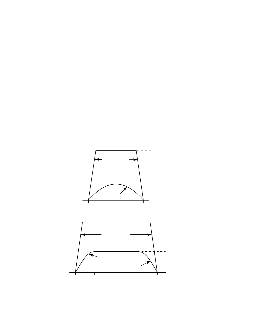
Figure 5 Input Voltage Template-10Mbps
a. Short Bit
3.1 V
Slope 0.5 V/ns
585 mV
585 mV sin (π ∗ t/PW)
0PW
b. Long Bit
3.1 V
Slope 0.5 V/ns
585 mV
585 mV sin (π ∗ t/PW)
585 mV sin [2 π (t − PW2)/PW]
0 PW/4 3PW/4 PW
April, 2002 Copyright © 1999-2002 by LSI Logic Corporation. All rights reserved.
Functional Description 27 of 88
Page 28

If the receiver is in the idle state and 10 consecutive code bits from the
receiver consist of a pattern that is neither /I/ I/ nor /J/K/ symbols but
does not contain at least 2 noncontiguous 0's, the data is ignored and
the receiver stays in the idle state.
3.12.2 10 Mbps
Since the idle period in 10 Mbps mode is defined to be the period when
no data is present on the TP inputs, then the start of packet for 10 Mbps
mode is detected when valid data is detected by the TP squelch circuit.
When start of packet is detected, CRS is asserted as described in the
Controller Interface section. Refer to the TP squelch section for 10 Mbps
mode for the algorithm for valid data detection.
3.13 End of Packet
3.13.1 100 Mbps
End of packet for 100 Mbps mode is indicated by the End of Stream
Delimiter (referred to as ESD). The ESD pattern consists of the two /T/R/
4B5B symbols inserted after the end of the packet, as defined in IEEE
802.3 Clause 24 and shown in Figure 2.
The transmit ESD is generated by the 4B5B encoder and the /T/R/
symbols are inserted by the 4B5B encoder after the end of the transmit
data packet, as shown in Figure 2.
The receive ESD pattern is detected by the 4B5B decoder by examining
groups of 10 consecutive code bits (two 5B words) from the descrambler
during valid packet reception to determine if there is an ESD.
If the 10 consecutive code bits from the receiver during valid packet
reception consist of the /T/R/ symbols, the end of packet is detected,
data reception is terminated, CRS and RX_DV are asserted, and /I/I/
symbols are substituted in place of the /T/R/ symbols.
If 10 consecutive code bits from the receiver during valid packet
reception do not consist of /T/R/ symbols but consist of /I/I/ symbols
instead, then the packet is considered to have been terminated
prematurely and abnormally. When this premature end of packet
condition is detected, RX_ER is asserted for the nibble associated with
the first /I/ symbol detected and then CRS and RX_DV are deasserted.
28 of 88 L80225 10/100 Mbps Ethernet Physical Layer Device - Technical Manual
April, 2002 Copyright © 1999-2002 by LSI Logic Corporation. All rights reserved.
Page 29

Premature end of packet condition is also indicated by setting the bad
ESD bit in the MI serial port Status Output register.
3.13.2 10 Mbps
The end of packet for 10 Mbps mode is indicated with the SOI (Start of
Idle) pulse. The SOI pulse is a positive pulse containing a Manchester
code violation inserted at the end of every packet .
The transmit SOI pulse is generated by the TP transmitter and inserted
at the end of the data packet after TX_EN is deasserted. The transmitted
SOI output pulse at the TP output is shaped by the transmit waveshaper
to meet the pulse template requirements specified in IEEE 802.3 Clause
14 and shown in Figure 6.
The receive SOI pulse is detected by the TP receiver by sensing missing
data transitions. Once the SOI pulse is detected, data reception is ended
and CRS and RX_DV are deasserted.
3.14 Link Integrity & Autonegotiation
3.14.1 General
The L80225 can be configured to implement either the standard link
integrity algorithms or the AutoNegotiation algorithm.
The standard link integrity algorithms are used solely to establish an
active link to and from a remote device. There are different standard link
integrity algorithms for 10 and 100 Mbps modes. The AutoNegotiation
algorithm is used for two purposes: (1) To automatically configure the
device for either 10/100 Mbps and Half/Full Duplex modes, and (2) to
establish an active link to and from a remote device. The standard link
integrity and AutoNegotiation algorithms are described below.
3.14.2 10Base-T Link Integrity Algorithm - 10Mbps
The L80225 uses the same 10Base-T link integrity algorithm that is
defined in IEEE 802.3 Clause 14. This algorithm uses normal link pulses,
referred to as NLP's and transmitted during idle periods, to determine if
a device has successfully established a link with a remote device (called
Link Pass state). The transmit link pulse meets the template defined in
April, 2002 Copyright © 1999-2002 by LSI Logic Corporation. All rights reserved.
Functional Description 29 of 88
Page 30

IEEE 802.3 Clause 14 and shown in Figure 7. Refer to IEEE 802.3
Clause 14 for more details if needed.
3.14.3 100Base-TX Link Integrity Algorithm -100Mbps
Since 100Base-TX is defined to have an active idle signal, then there is
no need to have separate link pulses like those defined for 10Base-T.
The L80225 uses the squelch criteria and descrambler synchronization
algorithm on the input data to determine if the device has successfully
established a link with a remote device (called Link Pass state). Refer to
IEEE 802.3 for both of these algorithms for more details.
3.14.4 AutoNegotiation Algorithm
As stated previously, the AutoNegotiation algorithm is used for two
purposes: (1) To automatically configure the device for either 10/100
Mbps and Half/Full Duplex modes, and (2) to establish an active link to
and from a remote device. The AutoNegotiation algorithm is the same
algorithm that is defined in IEEE 802.3 Clause 28. AutoNegotiation uses
a burst of link pulses, called fast link pulses and referred to as FLP's, to
pass up to 16 bits of signaling data back and forth between the L80225
and a remote device. The transmit FLP pulses meet the template
specified in IEEE 802.3 and shown in Figure 7. A timing diagram
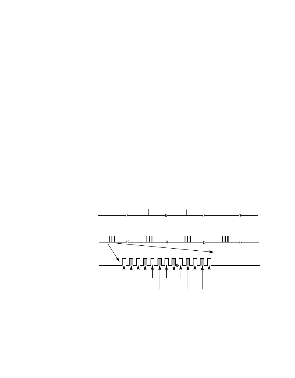
contrasting NLP's and FLP's is shown in Figure 8.
The AutoNegotiation algorithm is initiated by any of the following events:
(1) Powerup, (2) device reset, (3) AutoNegotiation reset, (4)
AutoNegotiation enabled, or (5) a device enters the Link Fail State. Once
a negotiation has been initiated, the L80225 first determines if the remote
device has AutoNegotiation capability. If the remote device is not
AutoNegotiation capable and is just transmitting either a 10Base-T or
100Base-TX signal, the L80225 will sense that and place itself in the
correct mode. If the L80225 detects FLP's from the remote device, then
the remote device is determined to have AutoNegotiation capability and
the device then uses the contents of the MI serial port AutoNegotiation
Advertisement register and FLP's to advertise its capabilities to a remote
device. The remote device does the same, and the capabilities read back
from the remote device are stored in the MI serial port AutoNegotiation
Remote End Capability register. The L80225 negotiation algorithm then
matches it's capabilities to the remote device's capabilities and
determines what mode the device should be configured to according to
the priority resolution algorithm defined in IEEE 802.3 Clause 28. Once
30 of 88 L80225 10/100 Mbps Ethernet Physical Layer Device - Technical Manual
April, 2002 Copyright © 1999-2002 by LSI Logic Corporation. All rights reserved.
Page 31

the negotiation process is completed, the L80225 then configures itself
for either 10 or 100 Mbps mode and either Full or Half Duplex modes
(depending on the outcome of the negotiation process), and it switches
to either the 100Base-TX or 10Base-T link integrity algorithms
(depending on which mode was enabled by AutoNegotiation). Refer to
IEEE 802.3 Clause 28 for more details.
3.14.5 AutoNegotiation Outcome Indication
The outcome or result of the AutoNegotiation process is stored in the
speed detect and duplex detect bits in the MI serial port Status Output
register.
3.14.6 AutoNegotiation Status
The status of the AutoNegotiation process can be monitored by reading
the AutoNegotiation acknowledgement bit in the MI serial port Status
register. The MI serial port Status register contains a single
AutoNegotiation acknowledgement bit, which indicates when an
AutoNegotiation has been initiated and successfully completed.
3.14.7 AutoNegotiation Enable
The AutoNegotiation algorithm can be enabled (or restarted) by setting
the AutoNegotiation enable bit in the MI serial port Control register or by
asserting the ANEG pin. When the AutoNegotiation algorithm is enabled,
the device halts all transmissions including link pulses for1200- 1500 ms,
enters the Link Fail State, and restarts the negotiation process. When the
AutoNegotiation algorithm is disabled, the selection of 100 Mbps or 10
Mbps modes is determined by the speed select bit in the MI serial port
Control register, and the selection of Half or Full Duplex is determined by
the duplex select bit in the MI serial port Control register.
3.14.8 AutoNegotiation Reset
The AutoNegotiation algorithm can be initiated at any time by setting the
AutoNegotiation reset bit in the MI serial port Control register.
3.14.9 Link Indication
Link activity is also indicated through two pins namely LA_LED and
L_LED. The LA_LED is asserted whenever a link is detected and starts
April, 2002 Copyright © 1999-2002 by LSI Logic Corporation. All rights reserved.
Functional Description 31 of 88
Page 32
3.15 Jabber
3.15.1 100 Mbps
3.15.2 10 Mbps
blinking on activity. The L_LED is asserted whenever the device goes
into the link pass state. The
LA_LED is open drain with pullup resistor
and can drive an LED from VDD. The L_LED output has both pullup and
pull down transistors in addition to a weak pullup resistor. Since this LED
is shared with the physical address input, this LED should only be driven
from Vdd.
Jabber function is disabled in the 100 Mbps mode.
Jabber condition occurs when the transmit packet exceeds a
predetermined length. When jabber is detected, the TP transmit outputs
are forced to the idle state, collision is asserted, and register bits in the
MI serial port Status and Status Output registers are set.
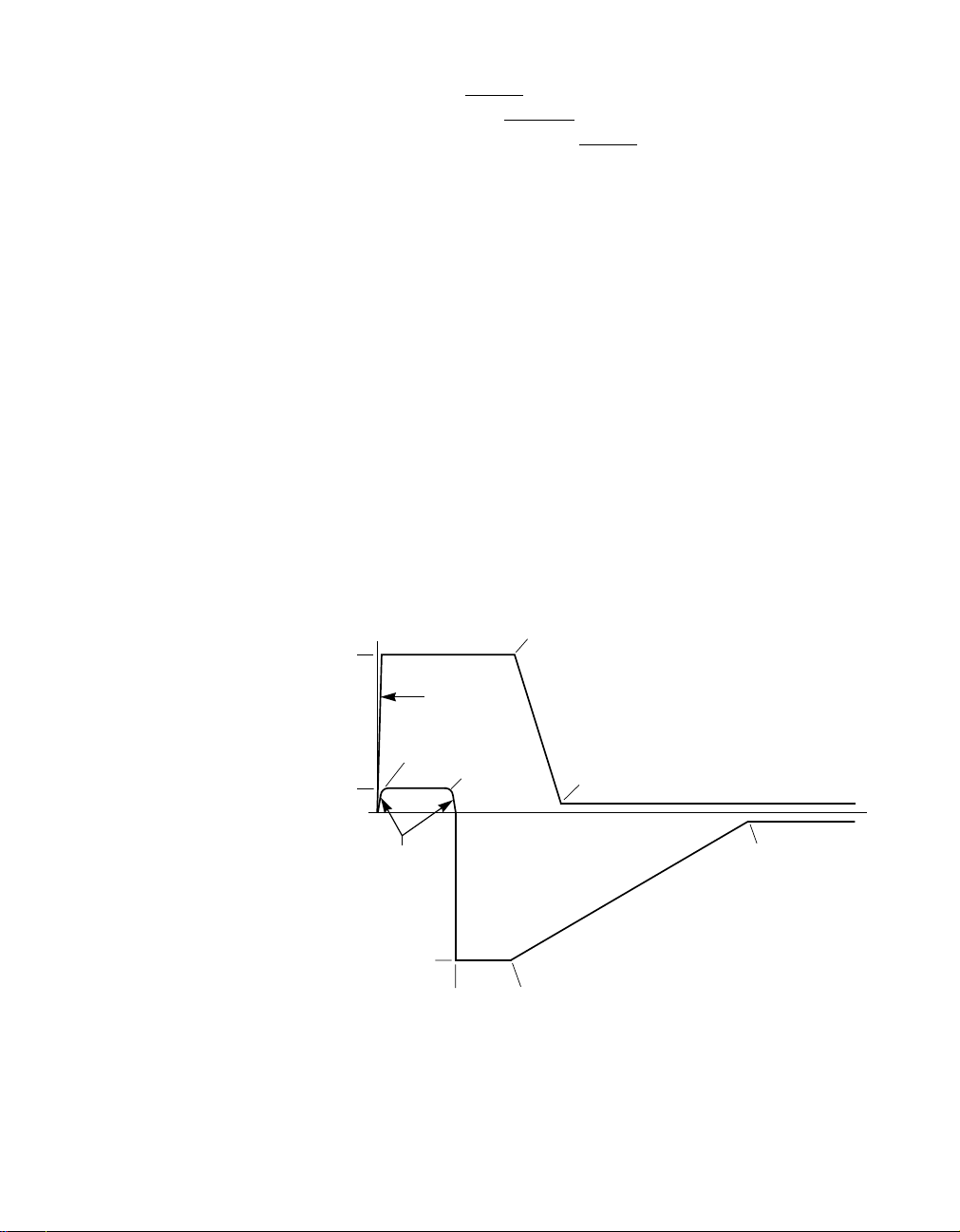
Figure 6 SOI Output Voltage Template - 10 Mbps
0 BT
3.1 V
0.5 V/ns
0.25 BT
2.25 BT
585 mV
585 mV sin (2 ∗π∗ (t/1 BT))
0 ≤ t ≤ 0.25 BT and
2.25 ≤ t ≤ 2.5 BT
−3.1 V
32 of 88 L80225 10/100 Mbps Ethernet Physical Layer Device - Technical Manual
April, 2002 Copyright © 1999-2002 by LSI Logic Corporation. All rights reserved.
4.5 BT
6.0 BT
+50 mV
−50 mV
45.0 BT
4.5 BT2.5 BT
Page 33

3.16 Receive Polarity Correction
3.16.1 100 Mbps
No polarity detection or correction is needed in 100 Mbps mode.
3.16.2 10 Mbps
The polarity of the signal on the TP receive input is continuously
monitored. If either 3 consecutive link pulses or one SOI pulse indicates
incorrect polarity on the TP receive input, the polarity is internally
determined to be incorrect.
The L80225 will automatically correct for the reverse polarity.
3.17 Full Duplex Mode
3.17.1 100 Mbps
Full Duplex mode allows transmission and reception to occur
simultaneously. When Full Duplex mode is enabled, collision is disabled
and internal TX_EN to CRS loopback is disabled.
The device can be either forced into Half or Full Duplex mode, or the
device can detect either Half or Full Duplex capability from a remote
device and automatically place itself in the correct mode.
The device can be forced into the Full or Half Duplex modes by either
setting the duplex bit in the MI serial port Control register or by asserting
the DPLX pin assuming AutoNegotiation is not enabled.
The device can automatically configure itself for Full or Half Duplex
modes by using the AutoNegotiation algorithm to advertise and detect
Full and Half Duplex capabilities to and from a remote terminal. All of this
is described in detail in the Link Integrity and AutoNegotiation section.
3.17.2 10 Mbps
Full Duplex in 10 Mbps mode is identical to the 100 Mbps mode.
April, 2002 Copyright © 1999-2002 by LSI Logic Corporation. All rights reserved.
Functional Description 33 of 88
Page 34
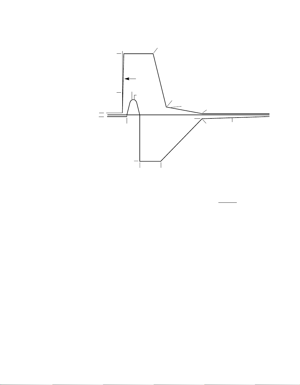
Figure 7 Link Pulse Output Voltage Template _ NLP, FLP
3.1 V
585 mV
+50 mV
−50 mV
3.17.3 Full Duplex Indication
Full Duplex detection can be monitored through the
is asserted low when the device is configured for Full Duplex operation.
This output has both pullup and pull down driver transistors and a weak
pullup resistor. Since this LED shared with the physical address input, it
should be driven only from Vdd.
0 BT
0.5 BT
0.25 BT
−3.1 V
0.5 V/ns
0.6 BT
1.3 BT
2.0 BT0.85 BT
2.0 BT
200 mV
300 mV
4.0 BT
4.0 BT
+50 mV
−50 mV
42.0 BT
F_LED pin. This pin
3.18 100/10 Mbps Selection
3.18.1 General
The device can be forced into either the 100 or 10 Mbps mode, or the
device also can detect 100 or 10 Mbps capability from a remote device
and automatically place itself in the correct mode.
The device can be forced into either the 100 or 10 Mbps mode by setting
the speed select bit in the MI serial port Control register or by
appropriately asserting the SPEED pin assuming AutoNegotiation is not
enabled.
34 of 88 L80225 10/100 Mbps Ethernet Physical Layer Device - Technical Manual
April, 2002 Copyright © 1999-2002 by LSI Logic Corporation. All rights reserved.
Page 35
The device can automatically configure itself for 100 or 10 Mbps mode
by using the AutoNegotiation algorithm to advertise and detect 100 and
10 Mbps capabilities to and from a remote terminal. All of this is
described in detail in the Link Integrity & AutoNegotiation section. There
is also a table that describes all these combinations in the ANEG pin
description.
3.18.2 10/100 Mbps Indication
Please refer to the application section for information on connecting two
LEDs to L_LED for indication of 10 and 100.
3.19 Loopback
3.19.1 Internal CRS Loopback
TX_EN is internally looped back onto CRS during every transmit packet.
This internal CRS loopback is disabled during collision, in Full Duplex
mode, and in Link Fail State. In 10 Mbps mode, internal CRS loopback
is also disabled when jabber is detected.
Figure 8 NLP vs. FLP Link Pulse
a. Normal Link Pulse (NLP)
TX_DI±
b. Fast Link Pulse (FLP)
TX_DI±
D0 D1 D2 D3 D14 D15
Clock Clock Clock Clock Clock Clock Clock
Data Data Data Data Data Data
3.19.2 Diagnostic Loopback
A diagnostic loopback mode can also be selected by setting the loopback
bit in the MI serial port Control register. When diagnostic loopback is
April, 2002 Copyright © 1999-2002 by LSI Logic Corporation. All rights reserved.
Functional Description 35 of 88
Page 36

3.20 Reset
3.21 Oscillator
enabled, TXD[3:0] data is looped back onto RXD[3:0], TX_EN is looped
back onto CRS, RX_DV operates normally, the TP receive and transmit
paths are disabled, the transmit link pulses are halted, and the Half/Full
Duplex modes do not change.
The device is reset when either (1) VDD is applied to the device, (2) the
reset bit is set in the MI serial port Control register, or (3) the RESET pin
is asserted active low. When reset is initiated by (1) or (2), an internal
power-on reset pulse is generated which resets all internal circuits, forces
the MI serial port bits to their default values, and latches in new values
for the MI address. After the power-on reset pulse has finished, the reset
bit in the MI serial port Control register is cleared and the device is ready
for normal operation. When reset is initiated by (3), the same procedure
occurs except the device stays in the reset state as long as the RESET
pin is held low. The RESET pin has an internal pullup to VDD. The device
is guaranteed to be ready for normal operation 50 ms after the reset was
initiated.
The L80225 requires a 25 MHz reference frequency for internal signal
generation. This 25 MHz reference frequency is generated by either
connecting an external 25 MHz crystal between OSCIN and GND or by
applying an external 25 MHz clock to OSCIN.
3.22 LED Drivers
The LA_LED and L_LED outputs are open drain with a pullup resistor
and can drive LED's tied to VDD. The FD_LED and L_LED outputs have
both pullup and pulldown driver transistors. Since these two LEDs also
36 of 88 L80225 10/100 Mbps Ethernet Physical Layer Device - Technical Manual
April, 2002 Copyright © 1999-2002 by LSI Logic Corporation. All rights reserved.
Page 37

share their outputs with the address inputs, they should be driven only
from Vdd.
Table 3 LED Event Definition
Symbol Definition
ACT Activity Occurred, Stretch Pulse to 100 ms
COL Collision Occurred, Stretch Pulse to 100 ms
LINK100 100 Mb Link Detected
LINK10 10 Mb Link Detected
LINK 100 or 10 Mb Link Detected
LINK+ACT 100 or 10 Mb Link Detected or Activity Occurred, Stretch Pulse
FDX Full Duplex Mode Enabled
10/100 10 Mb Mode Enabled (High), or 100 Mb Mode Enabled (Low)
3.23 Repeater Mode
The L80225 has one predefined repeater mode which can be enabled
by asserting the RPTR pin. When this repeater mode is enabled with the
RPTR pin, the device operation is altered as follows: (1) TX_EN to CRS
loopback is disabled.
3.24 MI Serial Port
3.24.1 Signal Description
The MI serial port has eight pins, MDC, MDIO, MDINT, and MDA[3:0].
MDC is the serial shift clock input. MDIO is a bidirectional data I/O pin.
MDINT is an interrupt output. MDA[3:0] are address pins for the MI serial
port.
To 100 ms (Link Detect Causes LED to be On, Activity Causes
LED to Blink)
MDA[3:0] inputs share the same pins as the LED outputs, respectively.
At powerup or reset, the LED output drivers are 3-stated for an interval
called the power-on reset time. During the power-on reset interval, the
April, 2002 Copyright © 1999-2002 by LSI Logic Corporation. All rights reserved.
Functional Description 37 of 88
Page 38

3.24.2 Timing
3.24.3 Bit Types
value on these pins is latched into the device, inverted, and used as the
MI serial port physical device addresses.
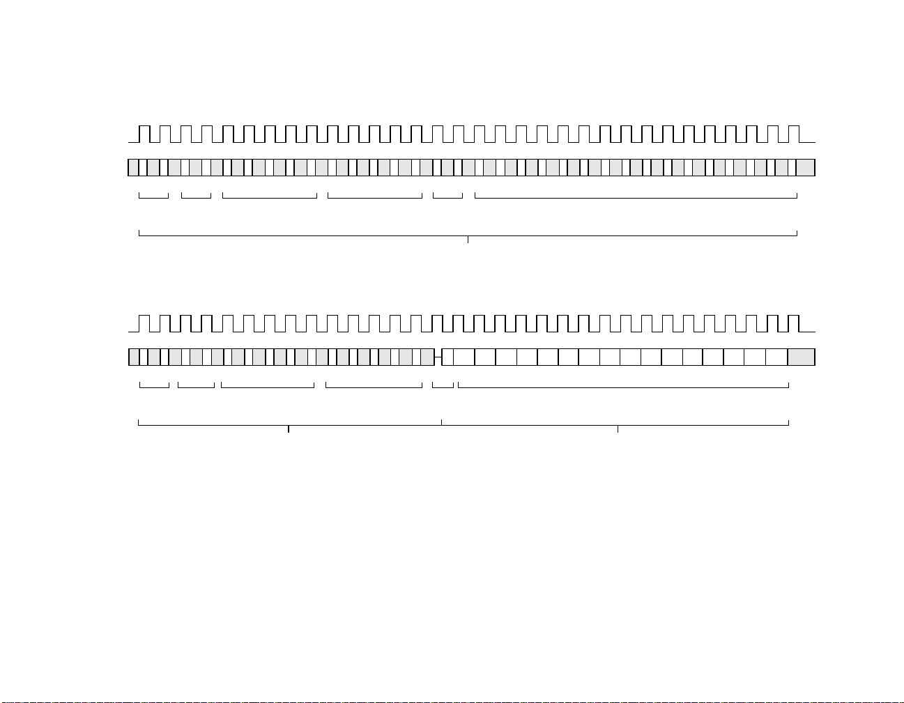
A timing diagram for a MI serial port frame is shown in Figure 9. The MI
serial port is idle when at least 32 continuous 1's are detected on MDIO
and remains idle as long as continuous 1's are detected. During idle,
MDIO is in the high impedance state. When the MI serial port is in the
idle state, a 01 pattern on the MDIO pin initiates a serial shift cycle. Data
on MDIO is then shifted in on the next 14 rising edges of MDC (MDIO is
high impedance). If the register access mode is not enabled, on the next
16 rising edges of MDC, data is either shifted in or out on MDIO,
depending on whether a write or read cycle was selected with the bits
READ and WRITE. After the 32 MDC cycles have been completed, one
complete register has been read/written, the serial shift process is halted,
data is latched into the device, and MDIO goes into high impedance
state. Another serial shift cycle cannot be initiated until the idle condition
(at least 32 continuous 1's) is detected.
Since the serial port is bidirectional, there are many types of bits. Write
bits (W) are inputs during a write cycle and are high impedance during
a read cycle. Read bits (R) are outputs during a read cycle and high
impedance during a write cycle. Read/Write bits (R/W) are actually write
bits, which can be read out during a read cycle. R/WSC bits are R/W bits
that are self-clearing after a set period of time or after a specific event
has completed. R/LL bits are read bits that latch themselves when they
go low, and they stay latched low until read. After they are read, they are
reset high. R/LH bits are the same as R/LL bits except that they latch
high. R/LT are read bits that latch themselves whenever they make a
transition or change value, and they stay latched until they are read. After
R/LT bits are read, they are updated to their current value. R/LT bits can
38 of 88 L80225 10/100 Mbps Ethernet Physical Layer Device - Technical Manual
April, 2002 Copyright © 1999-2002 by LSI Logic Corporation. All rights reserved.
Page 39

also be programmed to assert the interrupt function as described in the
Interrupt section. The bit type definitions are summarized in Table 4.
Table 4 MI Register Bit Type Definition
Definition
Sym. Name
W Write Input No operation, Hi Z
R Read No Operation, Hi Z Output
R/W Read/Write Input Output
R/WSC Read/Write Self
Clearing
R/LL Read/Latching
Low
R/LH Read/Latching
High
R/LT Read/Latching
on Transition
Write Cycle Read Cycle
Input Output
Clears itself after operation
completed
No Operation, Hi Z Output
When bit goes low, bit
latched.
When bit is read, bit
updated.
No Operation, Hi Z Output
When bit goes high, bit
latched.
When bit is read, bit
updated.
No Operation, Hi Z Output
When bit transitions, bit
latched and interrupt set.
When bit is read, interrupt
cleared and bit updated.
3.24.4 Frame Structure
The structure of the serial port frame is shown in Table 5, and a timing
diagram of a frame is shown in Figure 9. Each serial port access cycle
consists of 32 bits (or 192 bits if multiple register access is enabled and
REGAD[4:0]=11111), exclusive of idle. The first 16 bits of the serial port
cycle are always write bits and are used for addressing. The last 16/176
bits are from one/all of the 11 data registers.
The first 2 bits in Table 5 and Figure 6 are start bits and need to be
written as a 01 for the serial port cycle to continue. The next 2 bits are
April, 2002 Copyright © 1999-2002 by LSI Logic Corporation. All rights reserved.
Functional Description 39 of 88
Page 40

a read and write bit which determine if the accessed data register bits
will be read or write. The next bit has to be a zero. The next 4 bits are
device addresses and they must match the inverted values latched in
from pins MDA[3:0] during the power-on reset time for the serial port
access to continue. The next 5 bits are register address select bits that
select one of the five data registers for access. The next 1 bit is a
turnaround bit which is not an actual register bit but extra time to switch
MDIO from write to read if necessary, as shown in Figure 2. The final 16
bits of the MI serial port cycle (or 176 bits if multiple register access is
enabled and REGAD[4:0]=11111) come from the specific data register
designated by the register address bits REGAD[4:0].
3.24.5 Register Structure
The L80225 has six internal 16 bit registers. A map of the registers is
shown in Table 5.
The L80225 supports only the six registers mandated by the IEEE 802.3
specification.
The structure and bit definition of the Control register is shown in Table 6.
This register stores various configuration inputs and its bit definition
complies with the IEEE 802.3 specifications.
The structure and bit definition of the Status register is shown in Table 7.
This register contains device capabilities and status output information.
Its bit definition complies with the IEEE 802.3 specifications.
The structure and bit definition of the PHY ID #1 and #2 registers is
shown in Table 8 and Table 9, respectively. These registers contain an
identification code unique to the L80225 and their bit definition complies
with the IEEE 802.3 specifications.
The structure and bit definition of the AutoNegotiation Advertisement and
AutoNegotiation Remote End Capability registers is shown in Table 10
and Table 11, respectively. These registers are used by the
AutoNegotiation algorithm and their bit definition complies with the IEEE
802.3 specifications.
40 of 88 L80225 10/100 Mbps Ethernet Physical Layer Device - Technical Manual
April, 2002 Copyright © 1999-2002 by LSI Logic Corporation. All rights reserved.
Page 41
April, 2002 Copyright © 1999-2002 by LSI Logic Corporation. All rights reserved.
Functional Description 41 of 88
Figure 9 MI Serial Port Frame Timing Diagram
WRITE Cycle
0 1 2 3 4 5 6 7 8 9 10 11 12 13 14 15 16 17 18 19 20 21 22 23 24 25 26 27 28 29 30 31
MDC
MDIO
0101P4 P3 P2 P1 P0 R4 R3 R2 R1 R0 10D15 D14 D13 D12 D11 D10 D9 D8 D7 D6 D5 D4 D3 D2 D1 D0
ST[1:0] OP[1:0]
PHYAD[4:0]
REGAD[4:0]
TA[1:0]
DATA[15:0]
READ Cycle
0 1 2 3 4 5 6 7 8 9 10 11 12 13 14 15 16 17 18 19 20 21 22 23 24 25 26 27 28 29 30 31
MDC
MDIO
0101
ST[1:0] OP[1:0] PHYAD[4:0] REGAD[4:0] TA[1:0] DATA[15:0]
PHY Clocks In Data on Rising Edges of MDC
P4 P3
P2 P1 P0 R4 R3
R2 R1 R0 Z0
WRITE Bits
PHY Clocks In Data on Rising Edges of MDC
WRITE Bits
D15 D14 D13 D12 D11
PHY Clocks Out Data on Rising Edges of MDC
D9 D8 D7 D6 D5 D4 D3 D2 D1 D0
D10
READ Bits
Page 42
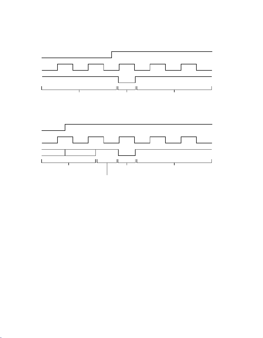
Internal
Interrupt
MDC
MDIO
Figure 10 MDIO Interrupt Pulse
a. Interrupt Happens During Idle
Internal
Interrupt
MDC
MDIO
MDIO High-Z
Pulled High Externally
B1 B0
Last Two Bits
of Read Cycle
Interrupt
Pulse
b. Interrupt Happens During Read Cycle
Interrupt
Pulse
MDIO High-Z
Pulled High Externally
Pulled High Externally
Pulled High Externally
MDIO High-Z
MDIO High-Z
42 of 88 L80225 10/100 Mbps Ethernet Physical Layer Device - Technical Manual
April, 2002 Copyright © 1999-2002 by LSI Logic Corporation. All rights reserved.
Page 43

4 Register Description
Table 5 MI Serial Port Frame Structure
<Idle> <Start> <Read> <Write> <PHY Addr.> <Reg. Addr.> <Turnaround> <Data>
IDLE ST[1:0] READ WRITE PHYAD[4:0] REGAD[4:0] TA[1:0] D[15:0]....
Register 0 Control
Register 1 Status
Register 2 PHY ID #1
Register 3 PHY ID #2
Register 4 AutoNegotiation Advertisement
Register 5 AutoNegotiation Remote End Capability
Symbol Name Definition R/W
IDLE Idle Pattern These bits are an idle pattern. Device will not initiate an
ST1
ST0
READ Read Select 1 = Read Cycle W
WRITE Write Select 1 = Write Cycle W
PHYAD[4:0] Physical Device
REGAD4[4:0] Register Address If REGAD[4:0]=00000-11110, these bits determine the
TA1
TA0
D[15:0].... Data These 16 bits contain data to/from one of the eleven reg-
Start Bits When ST[1:0]=01, an MI Serial Port access cycle starts. W
Address
Turnaround Time These bits provide some turnaround time for MDIO R/W
MI cycle until it detects at least 32 1's.
When PHYAD[3:0]=
= 0, the MI Serial Port is selected for operation.
specific register from which D[15:0] is read/written. If multiple register access is enabled and REGAD[4:0]=11111,
all registers are read/written in a single cycle.
When READ=1, TA[1:0]=Z0
When WRITE=1, TA[1:0]=ZZ
isters selected by register address bits REGAD[4:0].
MDA[3:0] pins inverted and PHYAD[4]
IDLE is shifted in first
April, 2002 Copyright © 1999-2002 by LSI Logic Corporation. All rights reserved.
Register Description 43 of 88
W
W
W
R/W
Any
Page 44

Table 6 MI Register 0 (Control) Structure And Bit Definition
0.15 0.14 0.13 0.12 0.11 0.10 0.9 0.8
RST LPBK SPEED ANEG_EN PDN MII_DIS ANEG_RST DPLX
R/WSC R/W R/W R/W R/W R/W R/WSC R/W
0.7 0.6 0.5 0.4 0.3 0.2 0.1 0.0
COLTST00000 00
R/W R/W R/W R/W R/W R/W R/W R/W
Bit Symbol Name Definition R/W Def.
0.15 RST Reset 1 = Reset, bit self clearing after reset complete
0 = Normal SC
0.14 LPBK Loopback
Enable
0.13 SPEED Speed
Select
1 = Loopback Mode Enabled
0 = Normal
1 = 100 Mbps Selected (100BaseTX)
0 = 10 Mbps Selected (10BaseT)
Note: Can be overridden with SPEED pin
0.12 ANEG_EN AutoNegoti-
ation Enable
1 = AutoNegotiation Enabled
0 = Normal
Note: Can be overridden with ANEG pin
0.11 PDN Powerdown
Enable
0.10 MII_DIS MIIInterface
Disable
0.9 ANEG_RST AutoNegotiation Reset
1 = Powerdown
0 = Normal
1 = MII Interface Disabled
0 = Normal
1 = Restart autonegotiation process, bit self
clearing after reset complete
0 = Normal
0.8 DPLX Duplex
Mode Select
1 = Full Duplex
0 = Half Duplex
Note: Can be overridden with DPLX pin
0.7 COLTST Collision
Test Enable
1 = Collision Test Enabled
0 = Normal
R/WSC0
R/W 0
R/W 1
R/W 1
R/W 0
R/W 1
R/WSC0
R/W 0
R/W 0
1
0.6thru
Reserved R/W 0
0.0
1. If MDA[3:0] not = 1111, then the MII_DIS default value is changed to 0.
x.15 Bit Is Shifted First
44 of 88 L80225 10/100 Mbps Ethernet Physical Layer Device - Technical Manual
April, 2002 Copyright © 1999-2002 by LSI Logic Corporation. All rights reserved.
Page 45

Table 7 MI Register 1 (Status) Structure And Bit Definition
1.15 1.14 1.13 1.12 1.11 1.10 1.9 1.8
CAP_T4 CAP_TXF CAP_TXH CAP_TF CAP_TH 0 0 0
R R R R R RRR
1.7 1.6 1.5 1.4 1.3 1.2 1.1 1.0
0 CAP_SUPR ANEG_ACK REM_FLT CAP_ANEG LINK JAB EXREG
R R R R/LH R R/LL R/LH R
Bit Symbol Name Definition R/W Def.
1.15 CAP_T4 100Base-T4
Capable
1.14 CAP_TXF 100Base-TX Full
Duplex Capable
1.13 CAP_TXH 100Base-TX Half
Duplex Capable
1.12 CAP_TF 10Base-T Full
Duplex Capable
1.11 CAP_TH 10Base-T Half
Duplex Capable
1.10
thru
1.7
1.6 CAP_SUPR MI Preamble
Suppression
Capable
1.5 ANEG_ACK AutoNegotiation
Acknowledgment
1.4 REM_FLT Remote Fault
Detect
0 = Not Capable of 100Base-T4 Operation R 0
1 = Capable of 100Base-TX Full Duplex R 1
1 = Capable of 100Base-TX Half Duplex R 1
1 = Capable of 10Base-T Full Duplex R 1
1 = Capable of 10Base-T Half Duplex R 1
Reserved R 0
0 = Not capable of accepting mi frames with
R0
mi preamble suppressed
1 = AutoNegotiation acknowledgement pro-
R0
cess complete
0 = Normal
1 = Remote Fault Detected. This bit is set
R/LH 0
when either Interrupt Detect bit 18.15 or
AutoNegotiation Remote Fault bit 5.13 is
set.
0 = No Remote Fault
1.3 CAP_ANEG AutoNegotiation
1 = Capable of AutoNegotiation Operation R 1
Capable
Register Description 45 of 88
April, 2002 Copyright © 1999-2002 by LSI Logic Corporation. All rights reserved.
Page 46

Bit Symbol Name Definition R/W Def.
1.2 LINK Link Status 1 = Link Detected (same as bit 18.14
1.1 JAB Jabber Detect 1 = Jabber detected (same as bit 18.8)
1.0 EXREG Extended Register Capable
inverted)
0 = Link Not Detected
0 = Normal
1 = Extended registers exist R 1
R/LL 0
R/LH 0
x.15 Bit Is Shifted First
Table 8 MI Register 2 (PHY ID #1) Structure And Bit Definition
2.15 2.14 2.13 2.12 2.11 2.10 2.9 2.8
OUI3 OUI4 OUI5 OUI6 OUI7 OUI8 OUI9 OUI10
RRRRRR RR
2.7 2.6 2.5 2.4 2.3 2.2 2.1 2.0
OUI11 OUI12 OUI13 OUI14 OUI15 OUI16 OUI17 OUI18
RRRRRR RR
Bit Symbol Name Definition R/W Def.
2.15
2.14
2.13
2.12
2.11
2.10
2.9
2.8
2.7
2.6
2.5
2.4
2.3
2.2
2.1
2.0
OUI3
OUI4
OUI5
OUI6
OUI7
OUI8
OUI9
OUI10
OUI11
OUI12
OUI13
OUI14
OUI15
OUI16
OUI17
OUI18
CompanyID, Bits 3-18 OUI = 00-A0-7D R 0
x.15 Bit Is Shifted First
46 of 88 L80225 10/100 Mbps Ethernet Physical Layer Device - Technical Manual
April, 2002 Copyright © 1999-2002 by LSI Logic Corporation. All rights reserved.
0
0
0
0
0
0
0
0
0
0
1
0
1
1
0
Page 47

Table 9 MI Register 3 (PHY ID #2) Structure And Bit Definition
3.15 3.14 3.13 3.12 3.11 3.10 3.9 3.8
OUI19 OUI20 OUI21 OUI22 OUI23 OUI24 PART5 PART4
RRRRRR RR
3.7 3.6 3.5 3.4 3.3 3.2 3.1 3.0
PART3 PART2 PART1 PART0 REV3 REV2 REV1 REV0
RRRRRR RR
Bit Symbol Name Definition R/W Def.
3.15
3.14
3.13
3.12
3.11
3.10
3.9
3.8
3.7
3.6
3.5
3.4
3.3
3.2
3.1
3.0
OUI19
OUI20
OUI21
OUI22
OUI23
OUI24
PART5
PART4
PART3
PART2
PART1
PART0
REV3
REV2
REV1
REV0
Company ID, Bits 19-24 OUI = 00-A0-7D R 1
Manufacturer's Part Number 03
H
R0
Manufacturer's Revision Number R –
x.15 Bit Is Shifted First
1
1
1
1
0
0
0
1
1
1
–
–
–
April, 2002 Copyright © 1999-2002 by LSI Logic Corporation. All rights reserved.
Register Description 47 of 88
Page 48

Table 10 MI Register 4 (AutoNegotiation Advertisement) Structure
4.15 4.14 4.13 4.12 4.11 4.10 4.9 4.8
NP ACK RF 0 0 0 T4 TX_FDX
R/W R R/W R/W R/W R/W R/W R/W
4.7 4.6 4.5 4.4 4.3 4.2 4.1 4.0
TX_HDX 10_FDX 10_HDX 0 0 0 0 CSMA
R/W R/W R/W R/W R/W R/W R/W R/W
Bit Symbol Name Definition R/W Def.
4.15 NP Next Page Enable 1 = Next Page Exists
1
0 = No Next Page
4.14 ACK Acknowledge 1 = Received AutoNegotiation Word Recognized
0 = Not Recognized
4.13 RF Remote Fault
Enable
4.12
1 = AutoNegotiation Remote Fault Detected
0 = No Remote Fault
Reserved R/W 0
thru
4.10
4.9 T4 100Base-T4
Capable
4.8 TX_FDX 100Base-TX Full
Duplex Capable
4.7 TX_HDX 100Base-TX Half
Duplex Capable
4.6 10_FDX 10Base-TX Full
Duplex Capable
4.5 10_HDX 10Base-TX Half
Duplex Capable
4.4
1 = Capable of 100Base-T4
0 = Not Capable
1 = Capable of 100Base-TX Full Duplex
0 = Not Capable
1 = Capable of 100Base-TX Half Duplex
0 = Not Capable
1 = Capable of 10Base-TX Full Duplex
0 = Not Capable
1 = Capable of 10Base-TX Half Duplex
0 = Not Capable
Reserved R/W 0
thru
4.1
R/W 0
R0
R/W 0
R/W 0
R/W 1
R/W 1
R/W 1
R/W 1
4.0 CSMA CSMA 802.3
Capable
1 = Capable of 802.3 CSMA Operation
0 = Not Capable
R/W 1
1. Next Page is currently not supported.
x.15 Bit Is Shifted First
48 of 88 L80225 10/100 Mbps Ethernet Physical Layer Device - Technical Manual
April, 2002 Copyright © 1999-2002 by LSI Logic Corporation. All rights reserved.
Page 49

Table 11 MI Register 5 (AutoNegotiation Remote End Capability) Structure
5.15 5.14 5.13 5.12 5.11 5.10 5.9 5.8
NP ACK RF 0 0 0 T4 TX_FDX
RRRRRR RR
5.7 5.6 5.5 5.4 5.3 5.2 5.1 5.0
TX_HDX 10_FDX 10_HDX 0 0 0 0 CSMA
RRRRRR RR
Bit Symbol Name Definition R/W Def.
5.15 NP Next Page Enable 1 = Next Page Exists
5.14 ACK Acknowledge 1 = Received AutoNegotiation Word
5.13 RF Remote Fault
Enable
5.12
thru
5.10
5.9 T4 100Base-T4
Capable
5.8 TX_FDX 100Base-TX Full
Duplex Capable
5.7 TX_HDX 100Base-TX Half
Duplex Capable
5.6 10_FDX 10Base-TX Full
Duplex Capable
5.5 10_HDX 10Base-TX Half
Duplex Capable
5.4
thru
5.1
0 = No Next Page
Recognized
0 = Not Recognized
1 = AutoNegotiation Remote Fault Detected
0 = No Remote Fault
Reserved R 0
1 = Capable of 100Base-T4
0 = Not Capable
1 = Capable of 100Base-TX Full Duplex
0 = Not Capable
1 = Capable of 100Base-TX Half Duplex
0 = Not Capable
1 = Capable of 10Base-TX Full Duplex
0 = Not Capable
1 = Capable of 10Base-TX Half Duplex
0 = Not Capable
Reserved R 0
R0
R0
R0
R0
R1
R0
R0
R0
5.0 CSMA CSMA 802.3
Capable
1 = Capable of 802.3 CSMA Operation
0 = Not Capable
x.15 Bit Is Shifted First
April, 2002 Copyright © 1999-2002 by LSI Logic Corporation. All rights reserved.
Register Description 49 of 88
R0
Page 50

Table 12 MI Register 18 (Status Output) Structure and Bit Definition
18.15 18.14 18.13 18.12 18.11 18.10 18.9 18.8
0 1 0000 00
R R/LT R/LT R/LT R/LT R/LT R/LT R/LT
18.7 18.6 18.5 18.4 18.3 18.2 18.1 18.0
SPD_DET DPLX_DET 0000 00
R/LTR/LTRRRR RR
Bit Symbol Name Definition R/W Def.
18.15 Reserved for factory use R 0
18.14 Reserved for factory use R/LT 1
18.13 Reserved for factory use R/LT 0
18.12 Reserved for factory use R/LT 0
18.11 Reserved for factory use R/LT 0
18.10 Reserved for factory use R/LT 0
18.9 Reserved for factory use R/LT 0
18.8 Reserved for factory use R/LT 0
18.7 SPD_DET 100/10 Speed
Detect
18.6 DPLX_DET Duplex Detect 1 = Device in Full Duplex
18.5
18.4
18.3
thru
18.0
1 = Device in 100 Mbps Mode (100Base-TX)
0 = Device in 10 Mbps Mode (10Base-T)
0 = Device in Half Duplex
Reserved for factory use R/LT 0
Reserved for factory use R 0
R/LT 1
R/LT 0
x.15 Bit Is Shifted First
50 of 88 L80225 10/100 Mbps Ethernet Physical Layer Device - Technical Manual
April, 2002 Copyright © 1999-2002 by LSI Logic Corporation. All rights reserved.
Page 51

5 Application Information
5.1 Example Schematics
A typical example schematic of the L80225 used in an adapter card
application is shown in Figure 11, a hub application is shown in
Figure 12, and an external PHY application is shown in Figure 13.
5.2 TP Transmit Interface
The interface between the TP outputs on TPO and the twisted pair
cable is typically transformer coupled and terminated with the two
resistors, as shown in Figure 11, Figure 12, and Figure 13.
The transformer for the transmitter is recommended to have a winding
ration of 1:1 with a center tap on the primary winding tied to VDD, as
shown in Figure 11, Figure 12, and Figure 13. The specifications for such
a transformer are shown in Table 13. Sources for the transformer are
listed in Table 14.
The transmit output needs to be terminated with two external termination
resistors in order to meet the output impedance and return loss
requirements of IEEE 802.3. It is recommended that these two external
resistors be connected from VDD to each of the TPO outputs, and their
value should be chosen to provide the correct termination impedance
when looking back through the transformer from the twisted pair cable,
as shown in Figure 11, Figure 12, and Figure 13. The value of these two
external termination resistors depends on the type of cable driven by the
device. Refer to the Cable Selection section for more details on choosing
the value of these resistors.
To minimize common mode output noise and to aid in meeting radiated
emissions requirements, it may be necessary to add a common mode
choke on the transmit outputs as well as add common mode bundle
termination. The qualified transformers mentioned in Table 14 all contain
common mode chokes along with the transformers on both the transmit
and receive sides, as shown in Figure 11, Figure 12, and Figure 13.
Common mode bundle termination may be needed and can be achieved
by tying the unused pairs in the RJ45 to chassis ground through 75 Ohm
April, 2002 Copyright © 1999-2002 by LSI Logic Corporation. All rights reserved.
Application Information 51 of 88
Page 52

resistors and a 0.01 uF capacitor, as shown in Figure 11, Figure 12, and
Figure 13.
To minimize noise pickup into the transmit path in a system or on a PCB,
the loading on TPO should be minimized and both outputs should
always be loaded equally.
5.3 TP Receive Interface
Receive data is typically transformer coupled into the receive inputs on
TPI and terminated with external resistors, as shown in Figure 11,
Figure 12, and Figure 13.
The transformer for the receiver is recommended to have a winding
ration of 1:1, as shown in Figure 11, Figure 12, and Figure 13. The
specifications for such a transformer are shown in Table 13. Sources for
the transformer are listed in Table 14.
The receive input needs to be terminated with the correct termination
impedance meet the input impedance and return loss requirements of
IEEE 802.3. In addition, the receive TP inputs need to be attenuated. It
is recommended that both the termination and attenuation be
accomplished by placing four external resistors in series across the TPI
inputs, as shown in Figure 11, Figure 12, and Figure 13. The resistors
should be 25%/25%/25%/25% of the total series resistance, and the total
series resistance should be equal to the characteristic impedance of the
cable (100 Ohms for UTP). It is also recommended that a 0.01µF
capacitor be placed between the center of the series resistor string and
VDD in order to provide an AC ground for attenuating common mode
signal at the input. This capacitor is also shown in Figure 11, Figure 12,
and Figure 13.
To minimize common mode input noise and to aid in meeting
susceptibility requirements, it may be necessary to add a common mode
choke on the receive input as well as add common mode bundle
termination. The qualified transformers mentioned in Table 14 all contain
common mode chokes along with the transformers on both the transmit
and receive sides, as shown in Figure 11, Figure 12, and Figure 13.
Common mode bundle termination may be needed and can be achieved
by tying the receive secondary center tap and the unused pairs in the
RJ45 to chassis ground through 75 Ohm resistors and a 0.01 µF
capacitor, as shown in Figure 11, Figure 12, and Figure 13.
52 of 88 L80225 10/100 Mbps Ethernet Physical Layer Device - Technical Manual
April, 2002 Copyright © 1999-2002 by LSI Logic Corporation. All rights reserved.
Page 53
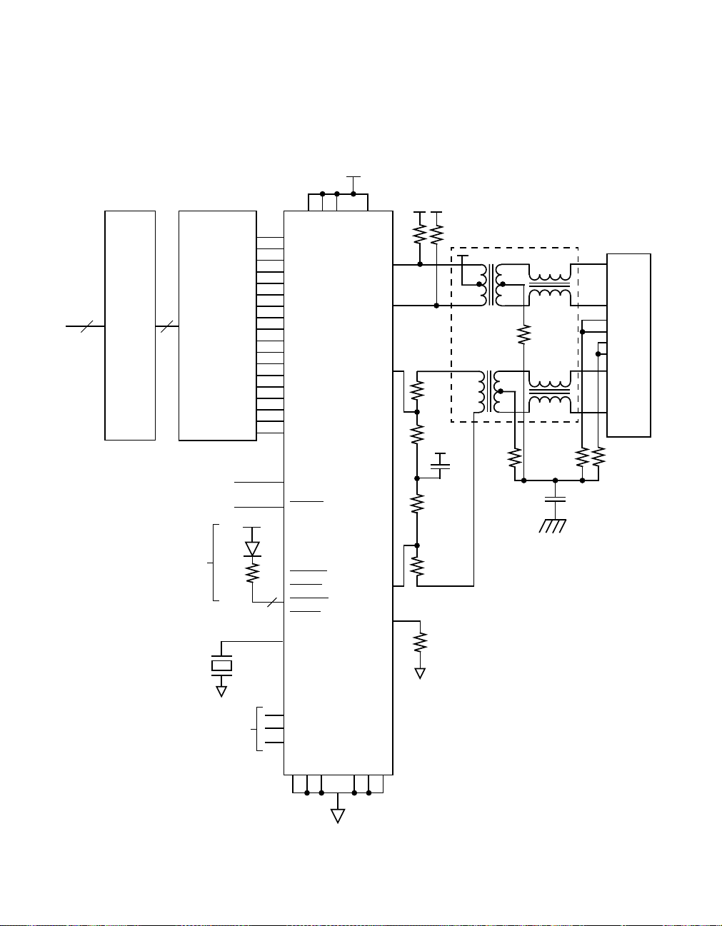
In order to minimize noise pickup into the receive path in a system or on
a PCB, loading on TPI should be minimized and both inputs should be
loaded equally.
Figure 11 Typical Network Interface Card Schematic Using L80225
System
Bus
Bus
Interface
80C300
or Equivalent
10/100 MB
Ethernet
Controller
To system
Reset or Float
4X
Optional
25 MHz
Optional
LED
500
4
TX_CLK
TXD3
TXD2
TXD1
TXD0
TX_EN
TX_ER
COL
RX_CLK
RXD3
RXD2
RXD1
RXD0
CRS
RX_DV
RX_ER
MDC
MDIO
RX_EN
RESET
LA_LED
C_LED
FD_LED
L_LED
OSCIN
VDD [4:1]
L80225
TPO+
TPO−
TPI+
TPI−
REXT
1%
50
50
1%
1:1
1
RJ45
2
4
5
7
8
3
6
75
0.01
2 KV
25
1%
25
1%
25
1%
25
1%
10 KΩ
1%
0.01
1:1
75
75
75
PINSTRAP
to VDD
or GND
SPEED
DPLX
ANEG
GND [6:1]
Application Information 53 of 88
April, 2002 Copyright © 1999-2002 by LSI Logic Corporation. All rights reserved.
Page 54
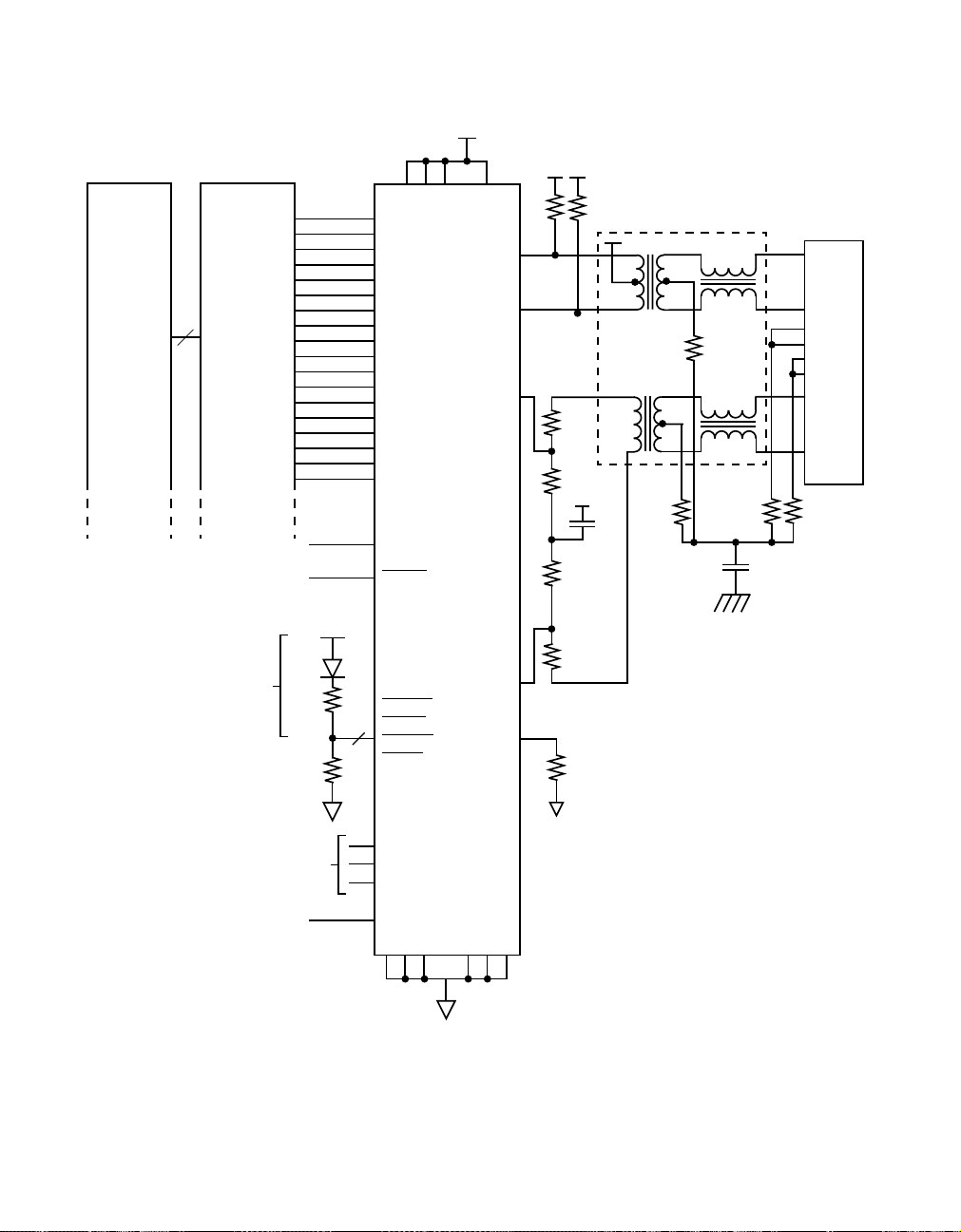
Figure 12 Typical Switching Port Schematic Using L80225
Switch
Fabric
80C300
Quad
100/10
Ethernet
Controller
To system
Reset or Float
4X
Optional
50 K
LED
500
Optional
4
TX_CLK
TXD3
TXD2
TXD1
TXD0
TX_EN
TX_ER
COL
RX_CLK
RXD3
RXD2
RXD1
RXD0
CRS
RX_DV
RX_ER
MDC
MDIO
RX_EN
RESET
LA_LED
C_LED
FD_LED
L_LED
VDD [4:1]
L80225
TPO+
TPO−
TPI+
TPI−
REXT
50
1%
25
1%
25
1%
25
1%
25
1%
10 KΩ
1%
50
1%
0.01
1:1
1:1
1
RJ45
2
4
75
75
75
0.01
5
7
8
3
6
75
2 KV
PINSTRAP
to VDD or GND
25 MHz
System Clock
SPEED
DPLX
ANEG
CSCIN
GND [6:1]
54 of 88 L80225 10/100 Mbps Ethernet Physical Layer Device - Technical Manual
April, 2002 Copyright © 1999-2002 by LSI Logic Corporation. All rights reserved.
Page 55
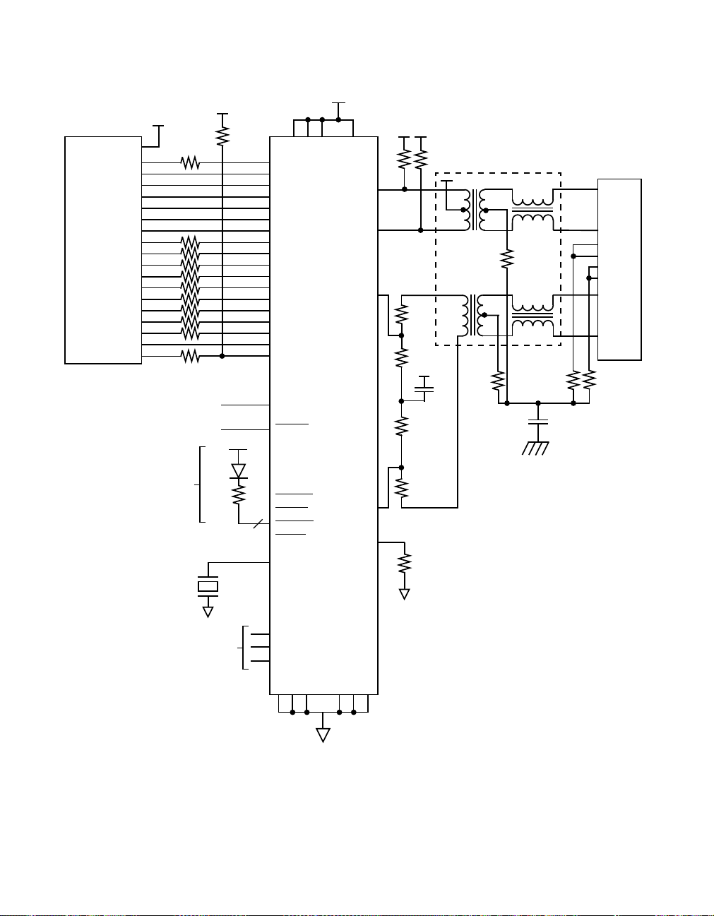
Figure 13 Typical External PHY Schematic Using L80225
1.5 K
5%
(Optional)
(Optional)
4
Ω
VDD [4:1]
TX_CLK
TXD3
TXD2
TXD1
TXD0
TX_EN
TX_ER
COL
RX_CLK
RXD3
RXD2
RXD1
RXD0
CRS
RX_DV
RX_ER
MDC
MDIO
RX_EN
RESET
LA_LED
C_LED
FD_LED
L_LED
OSCIN
L80225
TPO+
TPO−
TPI+
TPI−
REXT
1%
50
25
1%
25
1%
25
1%
25
1%
10 KΩ
1%
50
1%
0.01
MII
Connectors
4X
Optional
25 MHz
System Clock
24.9
1%
LED
500
1:1
1:1
1
RJ45
2
4
75
75
75
0.01
2 KV
5
7
8
3
6
75
PINSTRAP
to VDD or GND
SPEED
DPLX
ANEG
GND [6:1]
Application Information 55 of 88
April, 2002 Copyright © 1999-2002 by LSI Logic Corporation. All rights reserved.
Page 56

Table 13 Transformer Specification
Specification
Parameter
Turns Ratio 1:1 CT 1:1
Inductance, (µH Min) 350 350
Leakage Inductance, (µH) 0.05-0.15 0.0-0.2
Capacitance (pF Max) 15 15
DC Resistance (Ohms Max) 0.4 0.4
Transmit Receive
Table 14 TP Transformer Sources
Vendor Part Number
PULSE H1089, H1102
BEL S558-5999-J9, 558-5999-46
HALO TG22-3506ND, TG110-S050N2
PCA EPF8017GH
Note: H1089, S558-5999-46, EPF8017GH, and TG22-3506ND
are pin compatible. Please contact the transformer vendor
for additional information.
5.4 TP Transmit Output Current Set
The TPO output current level is set by an external resistor tied between
REXT and GND. This output current is determined by the following
equation where R is the value of REXT:
I
= (10K/R) I
out
Where I
= 40 mA (100 Mbps, UTP)
ref
= 32.6 mA (100 Mbps, STP)
= 100 mA (10 Mbps, UTP)
= 81.6 mA (10 Mbps, STP)
56 of 88 L80225 10/100 Mbps Ethernet Physical Layer Device - Technical Manual
April, 2002 Copyright © 1999-2002 by LSI Logic Corporation. All rights reserved.
ref
Page 57

REXT should be typically set to 10K Ohms and REXT should be a 1%
resistor in order to meet IEEE 802.3 specified levels. Once REXT is set
for the 100 Mbps and UTP modes as shown by the equation above, Iref
is then automatically changed inside the device when the 10 Mbps mode
or UTP120/STP150 modes are selected.
Keep REXT close to the REXT and GND pins as possible in order to
reduce noise pickup into the transmitter.
Since the TP output is a current source, capacitive and inductive loading
can reduce the output voltage level from the ideal. Thus, in actual
application, it might be necessary to adjust the value of the output current
to compensate for external loading. One way to adjust the TP output level
is to change the value of the external resistor tied to REXT.
5.5 Transmitter Droop
The IEEE 802.3 specification has a transmit output droop requirement for
100BaseTX. Since the L80225 TP output is a current source, it has no
perceptible droop by itself. However, the inductance of the transformer
added to the device transmitter output, as shown in Figure 11, Figure 12,
and Figure 13, will cause droop to appear at the transmit interface to the
TP wire. If the transformer connected to the L80225 outputs meets the
requirements in Table 13, the transmit interface to the TP cable will meet
the IEEE 802.3 droop requirements.
5.6 MII Controller Interface
5.6.1 General
The MII controller interface allows the L80225 to connect to any external
Ethernet controller without any glue logic provided that the external
Ethernet controller has a MII interface that complies with IEEE 802.3, as
shown in Figure 11, Figure 12, and Figure 13.
5.6.2 Clocks
Standard Ethernet controllers with a MII use TX_CLK to clock data in on
TXD[3:0]. TX_CLK is specified in IEEE 802.3 and on the L80225 to be
an output. If a nonstandard controller or other digital device is used to
interface to the L80225, there might be a need to clock TXD[3:0] into the
L80225 on the edges of an external master clock. The master clock, in
April, 2002 Copyright © 1999-2002 by LSI Logic Corporation. All rights reserved.
Application Information 57 of 88
Page 58

5.6.3 Output Drive
5.6.4 MII Disable
this case, would be an input to the L80225. This can be done by using
OSCIN as the master clock input; since OSCIN generates TX_CLK
inside the L80225, data on TXD[3:0] can be clocked into the L80225 on
edges of output clock TX_CLK or input clock OSCIN. In the case where
OSCIN is used as the input clock, a crystal is no longer needed on
OSCIN, and TX_CLK can be left open or used for some other purpose.
The digital outputs on the L80225 controller signals meet the MII driver
characteristics specified in IEEE 802.3 and shown in Figure 16 if external
24.9 ohm 1% termination resistors are added. These termination
resistors are only needed if the outputs have to drive a MII cable or other
transmission line type load, such as in the external PHY application
shown in Figure 13. If the L80225 is used in embedded applications,
such as adapter cards and switching hubs shown in Figure 11 and
Figure 12, then these terminations resistors are not needed.
The MII outputs can be placed in the high impedance state and inputs
disabled by setting the MII disable bit in the MI serial port Control
register. When this bit is set to the disable state, the TP outputs are also
disabled and transmission is inhibited. The default value of this bit when
the device powers up or is reset is dependent on the physical device
address. If the device address latched into
MDA[3:0] at reset is 1111, it
is assumed that the device is being used in applications where there
maybe more than one device sharing the MII bus, like external PHY's or
adapter cards, so the device powers up with the MII interface disabled.
If the device address latched into MDA[3:0] at reset is not 1111, it is
assumed that the device is being used in application where it is the only
device on the MII bus, like hubs, so the device powers up with the MII
interface enabled.
58 of 88 L80225 10/100 Mbps Ethernet Physical Layer Device - Technical Manual
April, 2002 Copyright © 1999-2002 by LSI Logic Corporation. All rights reserved.
Page 59
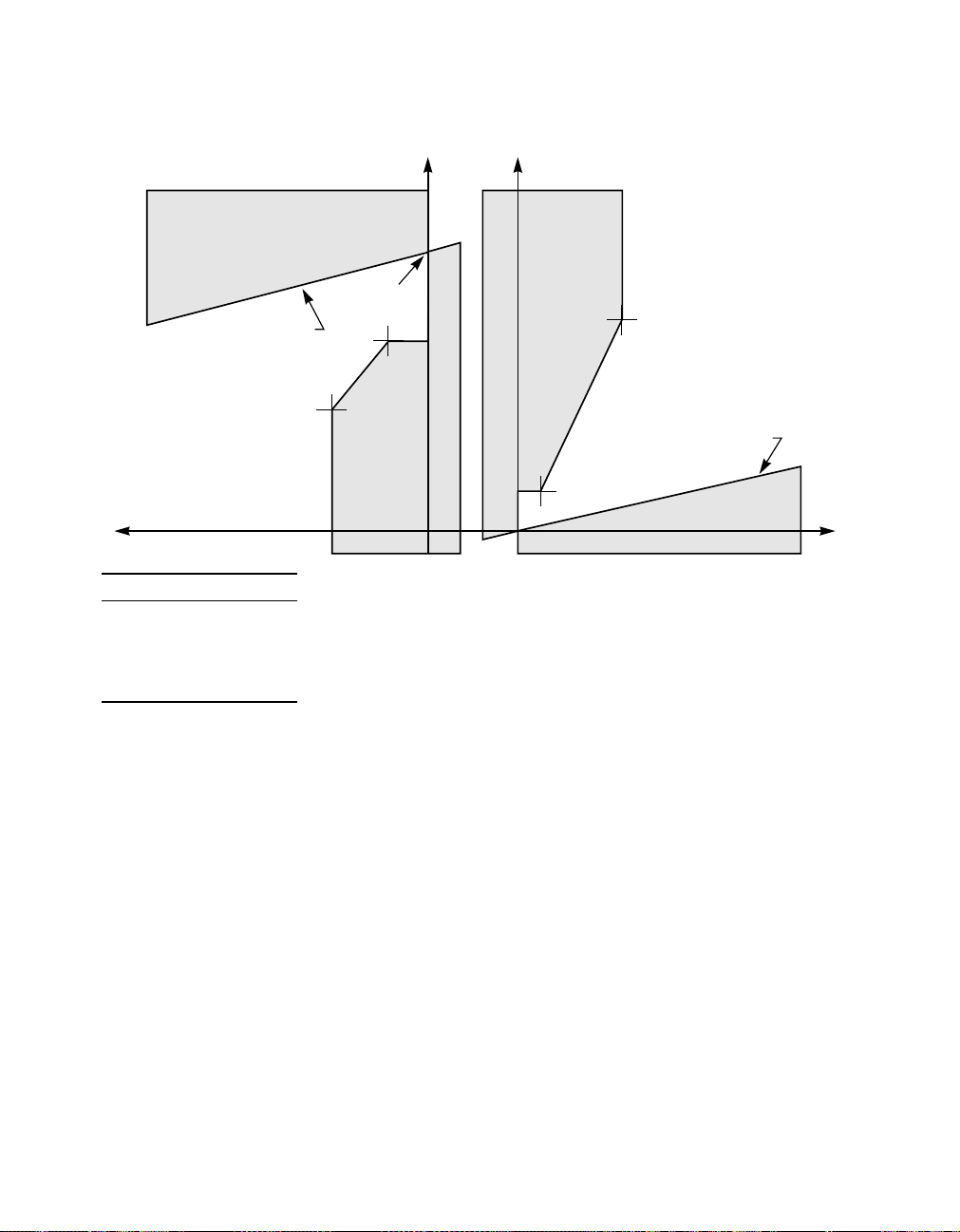
Figure 14 MII Output Driver Characteristics
Voh Vol
V
DD
I
Rol
= 40 ohm
min
I
V
1
loh lol
2
V
2
1
V
3
I
3
V
4
I
4
= 40 ohm
Rol
min
I – V
I1, V
I2, V
I3, V
I4, V
I (mA)
1
2
3
4
−20
−4
4
43
V (Volts)
1.10
2.40
0.40
3.05
5.6.5 Receive Output Enable
The receive output enable pin, RX_EN, forces the receive and collision
MII/FBI outputs into the high impedance state. More specifically, when
RX_EN is deasserted, RX_CLK, RXD[3:0], RX_DV, RX_ER, and COL
are placed in high impedance.
RX_EN can be used to "wire OR" the outputs of many L80225 devices
in multiport applications where only one device may be receiving at a
time, like a repeater. By monitoring CRS from each individual port, the
repeater can assert only the one RX_EN to that L80225 device which is
receiving data. The method will reduce, by 8 per device, the number of
pins and PCB traces required by a repeater core IC.
April, 2002 Copyright © 1999-2002 by LSI Logic Corporation. All rights reserved.
Application Information 59 of 88
Page 60

The RX_EN function can be enabled by appropriately setting the R/J
Configuration select bit in the MI serial port Configuration 2 register.
When this bit is set, the RX_EN pin becomes RX_EN.
5.7 Repeater Applications
5.7.1 MII Based Repeaters
The L80225 can be used as the physical interface for MII based
repeaters by using the standard MII as the interface to the repeater core.
For most repeaters, it is necessary to disable the internal CRS loopback.
For some particular types of repeaters, it may be desirable to either
enable or disable AutoNegotiation, force Half Duplex operation, and
enable either 100 Mbps or 10 Mbps operation. All of these modes can
be configured by setting the appropriate bits in the MI serial port Control
register or by enabling/disabling the Speed, Duplx and ANEG pins.
The L80225 has a RPTR pin which will automatically configure the
device for one common type of repeater application. When the RPTR pin
is asserted, the TX_EN to CRS loopback is automatically disabled.
The MII requires 16 signals between the L80225 and a repeater core.
The MII signal count to a repeater core will be 16 multiplied by the
number of ports, which can be quite large. The signal count between the
L80225 and repeater core can be reduced by 8 per device by sharing
the receive output pins and using RX_EN to enable only that port where
CRS is asserted. Refer to the Controller Interface section within the
Applications section for more details about RX_EN.
5.7.2 Clocks
Normally, transmit data over the MII/FBI is clocked into the L80225 with
edges from the output clock TX_CLK. It may be desirable or necessary
in some repeater applications to clock in the transmit data from a master
clock from the repeater core. This would require that transmit data be
clocked in on edges of an input clock. An input clock is available for
clocking in data on TXD with the OSCIN pin. Notice from the timing
diagrams that OSCIN generates TX_CLK, and TXD data is clocked in on
TX_CLK edges. This means that TXD data is also clocked in on OSCIN
60 of 88 L80225 10/100 Mbps Ethernet Physical Layer Device - Technical Manual
April, 2002 Copyright © 1999-2002 by LSI Logic Corporation. All rights reserved.
Page 61

5.8 Serial Port
5.8.1 General
edges as well. Thus, an external clock driving the OSCIN input can also
be used as the clock for TXD.
The L80225 has a MI serial port to access the device’s configuration
inputs and read out the status outputs. Any external device that has a
IEEE 802.3 compliant MI interface can connect directly to the L80225
without any glue logic, as shown in Figure 11, Figure 12, and Figure 13.
As described earlier, the MI serial port consists of 8 lines: MDC, MDIO,
MDINT, and MDA[3:0]. However, only 2 lines, MDC and MDIO, are
needed to shift data in and out; MDINT and MDA[3:0] are not needed but
are provided for convenience only.
Note that the MDA[3:0] addresses are inverted inside the L80225 before
going to the MI serial port block. This means that the MDA[3:0] pins
would have to be pin strapped to 1111 externally in order to successfully
match the MI physical address of 00000 on the PHYAD[4:0] bits
internally. The MSB of the address is internally tied to zero.
5.8.2 Serial Port Addressing
The device address for the MI serial port are selected by tying the
MDA[3:0] pins to the desired value. MDA[3:0] share the same pins as the
LED outputs, respectively, as shown in part a. of Figure 15.Atpowerup
or reset, the output drivers are 3-stated for an interval called the poweron reset time. During the power-on reset interval, the value on these pins
is latched into the device, inverted, and used as the MI serial port
address. The LED outputs are open drain with internal resistor pullup to
VDD.
If an LED is desired on the LED outputs, then an LED and resistor are
tied to VDD as shown in part b. of Figure 15. If a high address is desired,
then the LED to VDD automatically makes the latched address value a
high. If a low value for the address is desired, then a 50K resistor to GND
must be added as shown in part b. of Figure 15.
If no LED's are needed on the LED outputs, the selection of addresses
can be done as shown in part c. of Figure 15. If a high address is
April, 2002 Copyright © 1999-2002 by LSI Logic Corporation. All rights reserved.
Application Information 61 of 88
Page 62
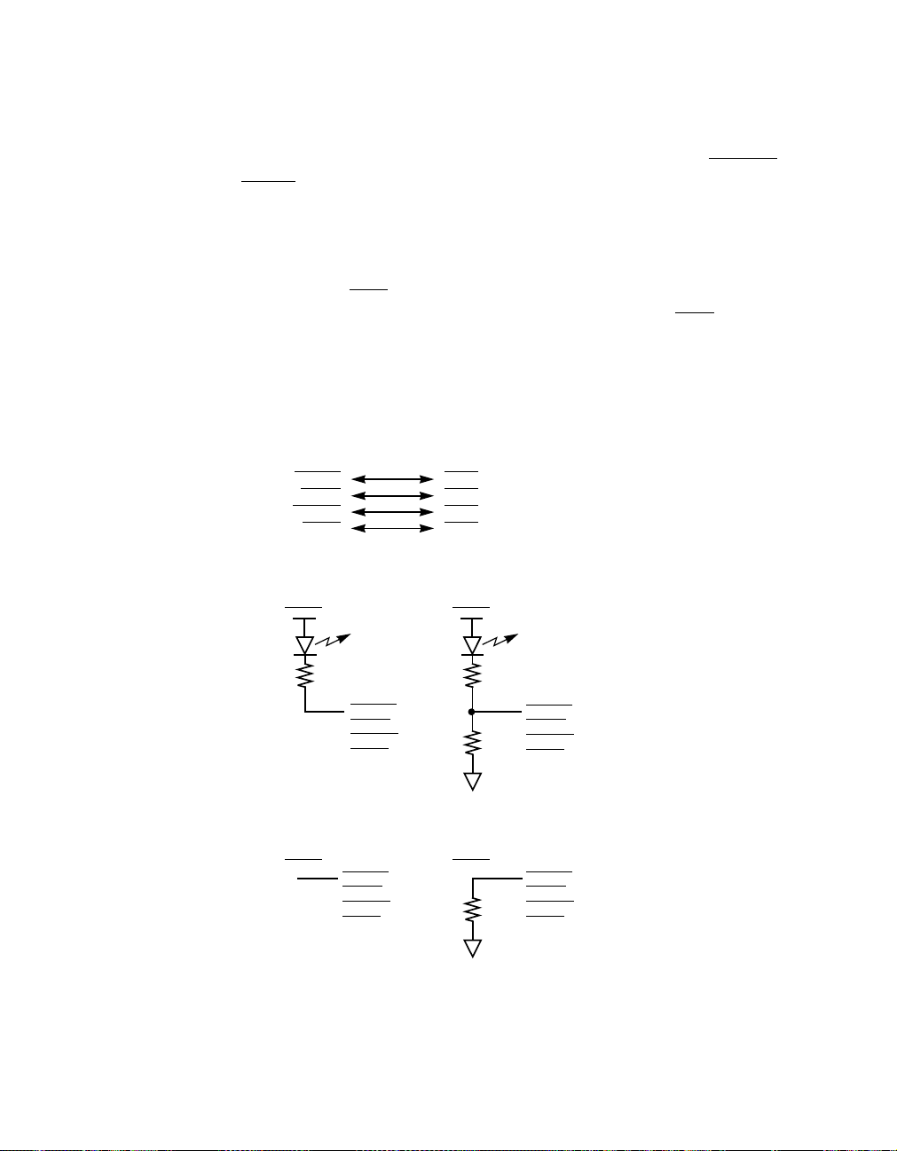
desired, the pin should be left floating and the internal pullup will pull the
pin high during power-on reset time and latch in a high address value. If
a low address is desired, then the LED output pins should be tied either
directly to GND or through an optional 50K resistor to GND. FD_LED and
L_LED should always be tied through a 50K resistor to GND since they
have both pullup and pulldown capability. The optional 50K resistor also
allows the Link, Full Duplex, and Collision LED pins to be used as digital
outputs under normal conditions.
Note that the MDA[3:0] addresses are inverted inside the L80225 before
going to the MI serial port block. This means that the
MDA[3:0] pins
would have to be pin strapped to 1111 externally in order to successfully
match the MI physical address bits PHYAD[4:0]=00000 internally.
Figure 15 Serial Device Port Address Selection
a. Output Driver/Input Address Correspondence
LA_LED
C_LED
FD_LED
L_LED
b. Setting Address with LEDs
High
MDA3
MDA2
MDA1
MDA0
Low
500
LA_LED
C_LED
FD_LED
L_LED
500
50K
LA_LED
C_LED
FD_LED
L_LED
c. Setting Address without LEDs
High Low
50K
LA_LED
C_LED
FD_LED
L_LED
Float
LA_LED
C_LED
FD_LED
L_LED
62 of 88 L80225 10/100 Mbps Ethernet Physical Layer Device - Technical Manual
April, 2002 Copyright © 1999-2002 by LSI Logic Corporation. All rights reserved.
Page 63

5.9 Oscillator
The L80225 requires a 25 MHz reference frequency for internal signal
generation. This 25 MHz reference frequency can be generated by either
connecting an external 25 MHz crystal between OSCIN and GND or by
applying an external 25 MHz clock to OSCIN.
If the crystal oscillator is used, it needs only a crystal, and no other
external capacitors or other components are required. The crystal must
have the characteristics shown in Table 15. The crystal must be placed
as close as possible to OSCIN and GND pins so that parasitics on
OSCIN are kept to a minimum.
Table 15 Crystal Specifications
Parameter Spec
Type Parallel Resonant
Frequency 25 MHz 0.01%
Equivalent Series Resistance 25 ohms max
Load Capacitance 18 pF typ
Case Capacitance 7 pF max
Power Dissipation 1 mW max
5.10 LED Drivers
The LED outputs can all drive LED's tied to VDD, as shown in Figure 11,
Figure 12, and Figure 13.
The LED outputs can also drive other digital inputs. Thus, LED can also
be used as digital outputs whose function can be user defined and
controlled through the MI serial port.
5.11 Power Supply Decoupling
There are four VDDs on the L80225 (VDD[4:1]) and six GNDs
(GND[6:1]).
All six VDDs should be connected together as close as possible to the
device with a large VDD plane. If the VDDs vary in potential by even a
April, 2002 Copyright © 1999-2002 by LSI Logic Corporation. All rights reserved.
Application Information 63 of 88
Page 64

small amount, noise and latchup can result. The VDD's should be kept
to within 50 mV of each other.
All six GNDs should also be connected together as close as possible to
the device with a large ground plane. If the GNDs vary in potential by
even a small amount, noise and latchup can result. The VDD's should be
kept to within 50 mV of each other.
A 0.01-0.1 µF decoupling capacitor should be connected between each
VDD/GND set as close as possible to the device pins, preferably within
0.5". The value should be chosen on the basis of whether the noise from
VDD-GND is high or low frequency. A conservative approach would be
to use two decoupling capacitors on each VDD/GND set, one 0.1 µffor
low frequency and one 0.001 µf for high frequency noise on the power
supply.
The VDD connection to the transmit transformer center tap shown in
Figure 11, Figure 12, and Figure 13 has to be well decoupled in order to
minimize common mode noise injection from the supply into the twisted
pair cable. It is recommended that a 0.01 µF decoupling capacitor be
placed between the center tap VDD to the S004 GND plane. This
decoupling capacitor should be physically placed as close as possible to
the transformer center tap, preferably within 0.5"
The PCB layout and power supply decoupling discussed above should
provide sufficient decoupling to achieve the following when measured at
the device: (1) The resultant AC noise voltage measured across each
VDD/GND set should be less than 100 mVpp, (2) All VDD's should be
within 50 mVpp of each other, and (3) All GNDs should be within 50
mVpp of each other.
64 of 88 L80225 10/100 Mbps Ethernet Physical Layer Device - Technical Manual
April, 2002 Copyright © 1999-2002 by LSI Logic Corporation. All rights reserved.
Page 65
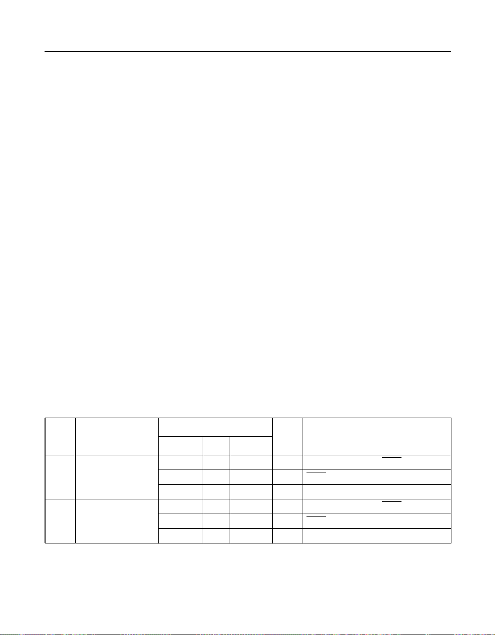
6 Specifications
6.1 Absolute Maximum Ratings
Absolute maximum ratings are limits beyond which may cause
permanent damage to the device or affect device reliability. All voltages
are specified with respect to GND, unless otherwise specified.
• VDD Supply Voltage -0.3 V to +4.0 V
• All Inputs and Outputs -0.3 V to 5.5 V
• Package Power Dissipation 2.0 Watt @ 70 °C
• Storage Temperature -65 to +150 °C
• Temperature Under Bias -10 to +80 °C
• Lead Temperature (Soldering, 10 Sec) 260 °C
• Body Temperature (Soldering, 30 Sec) 220 °C
6.2 DC Electrical Characteristics
Unless otherwise noted, all test conditions are as follows:
1. TA=0to+70°C
2. VDD= 3.3 V 5%
3. 25 MHz 0.01%
4. REXT = 10K 1%, no load
Limit
Sym. Parameter
VIL Input Low Voltage 0.8 Volt All except OSCIN,
VDD-1.0 Volt
1.5 Volt OSCIN
VIH Input High Voltage 2 5.5 Volt All except OSCIN,
VDD -0.5 Volt
2.5 Volt OSCIN
Specifications 65 of 88
April, 2002 Copyright © 1999-2002 by LSI Logic Corporation. All rights reserved.
Unit ConditionsMin Typ Max
MDA[3:0]
MDA[3:0]
MDA[3:0],
MDA[3:0],
Page 66

Limit
Sym. Parameter
Unit ConditionsMin Typ Max
IIL Input Low Current -1 uA VIN=GND. All except OSCIN,
MDA[3:0], RESET
-4 -25 uA VIN=GND.
MDA[3:0]
-12 -120 uA VIN=GND. RESET
-150 uA VIN=GND. OSCIN
IIH Input High Current 1 uA VIN=VDD. All except OSCIN, RPTR
12 120 uA VIN=VDD. RPTR
150 uA VIN=VDD. OSCIN
VOL Output Low
Voltage
VOH Output High
Voltage
VDD-1.0 Volt IOH=4 mA. All except LED
2.4 Volt IOH=4 uA.
VDD-1.0 Volt IOH=10mA.
0.4 Volt IOL=-4 mA. All except LED
1 Volt IOL=-10 mA. LED
L_LED
FD_LED
CIN Input Capacitance 5 pF
IDD VDD Supply
Current
IGND GND Supply
Current
IPDN PowerdownSupply
120 mA Transmitting, 100 Mbps
140 mA Transmitting, 10 Mbps
190 mA Transmitting, 100 Mbps
220 mA Transmitting, 10 Mbps
1
1
200 uA Powerdown, either IDD or IGND
Current
1. IGND includes current flowing into GND from the external resistors and transformer on TPO as
shown in Figure 11.
66 of 88 L80225 10/100 Mbps Ethernet Physical Layer Device - Technical Manual
April, 2002 Copyright © 1999-2002 by LSI Logic Corporation. All rights reserved.
Page 67

6.3 Twisted Pair Characteristics, Transmit
Unless otherwise noted, all test conditions are as follows:
1. T
=0to+70°C
A
2. VDD= 3.3 V 5%
3. 25 MHz 0.01%
4. REXT = 10K 1%, no load
5. TPO loading shown in Figure 11, or equivalent.
Limit
Sym. Parameter
TP Differential Output
T
OV
Voltage
T
T
T
TP Differential Output
OVS
Voltage Symmetry
TP Differential Output
ORF
Rise And Fall Time
TP Differential Output
ORFS
Rise And Fall Time
Symmetry
T
T
T
T
TP Differential Output
ODC
Duty Cycle Distortion
TP Differential Output
T
OJ
Jitter
TP Differential Output
T
OO
Overshoot
TP Differential Output
OVT
Voltage Template
TP Differential Output
SOI
SOI Voltage Template
TP Differential Output
LPT
Link Pulse Voltage
Template
T
TP Differential Output
OIV
Idle Voltage
Unit ConditionsMin Typ Max
0.950 1.000 1.050 V pk 100 Mbps, UTP Mode, 100 Ohm
load
2.2 2.5 2.8 V pk 10 Mbps, UTP Mode, 100 Ohm
load
98 102 % 100 Mbps, ratio of positive and
negative amplitude peaks on
TPO
3.0 5.0 ns 100 Mbps
0.5 ns 100Mbps, Difference between rise
and fall times on TPO
0.25 ns 100 Mbps, Output Data = 0101...
NRZ Pattern unscrambled, measure at 50% points
1.4 ns 100 Mbps, Output Data=scrambled /H/
5.0 % 100 Mbps
See Figure 4 10 Mbps
See Figure 6 10 Mbps
See Figure 7 10 Mbps, NLP and FLP
50 mV 10 Mbps. Measured on secondary
side of Xfmr in Figure 11.
April, 2002 Copyright © 1999-2002 by LSI Logic Corporation. All rights reserved.
Specifications 67 of 88
Page 68
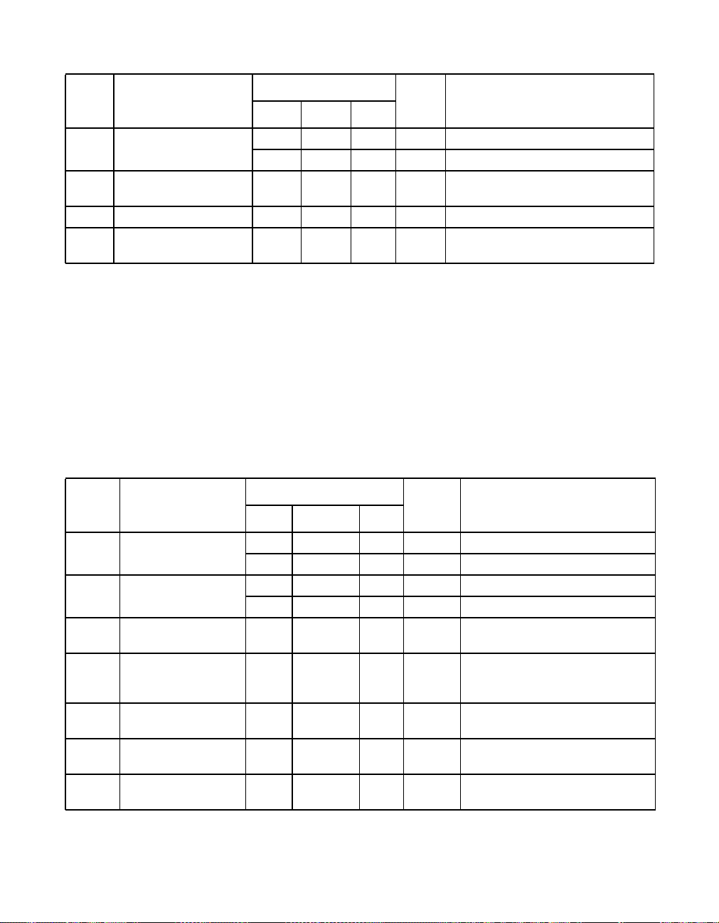
Limit
Sym. Parameter
T
TP Output Current 38 40 42 mA pk 100 Mbps
OIA
88 100 112 mA pk 10 Mbps
T
TP Output Current
OIR
Adjustment Range
TP Output Resistance 10K Ohm
T
OR
TP Output
T
OC
Capacitance
0.80 1.2 VDD= 3.3V, Adjustable with REXT,
15 pF
6.4 Twisted Pair Characteristics, Receive
Unless otherwise noted, all test conditions are as follows:
1. TA=0to+70°C
2. VCC= 3.3 V 5%
3. 25 MHz 0.01%
4. REXT = 10K 1%, no load
5. 62.5/10 MHz Square Wave on TP inputs in 100/10 Mbps
Limit
Sym. Parameter
R
R
R
R
OCV
CMR
R
R
R
TP Input Squelch
ST
Threshold
TP Input Unsquelch
UT
Threshold
TP Input Open Cir-
cuit Voltage
TP Input Common
Mode Voltage
Range
TP Input Differential
DR
Voltage Range
TP Input
IR
Resistance
TP Input
IC
Capacitance
166 500 mV pk 100 Mbps, RLVL=0
310 540 mV pk 10 Mbps, RLVL=0
100 300 mV pk 100 Mbps, RLVL=0
186 324 mV pk 10 Mbps, RLVL=0
VDD–2.4
± 0.2
R
OCV
0.25
V
DD
5K Ohm
10 pF
Unit ConditionsMin Typ Max
relative to T
with REXT=10K
OIA
Unit ConditionsMin Typ Max
Volt Voltage on either TPI+ or TPI–
with respect to GND.
Volt Voltage on TPI with respect to
GND.
Volt
68 of 88 L80225 10/100 Mbps Ethernet Physical Layer Device - Technical Manual
April, 2002 Copyright © 1999-2002 by LSI Logic Corporation. All rights reserved.
Page 69
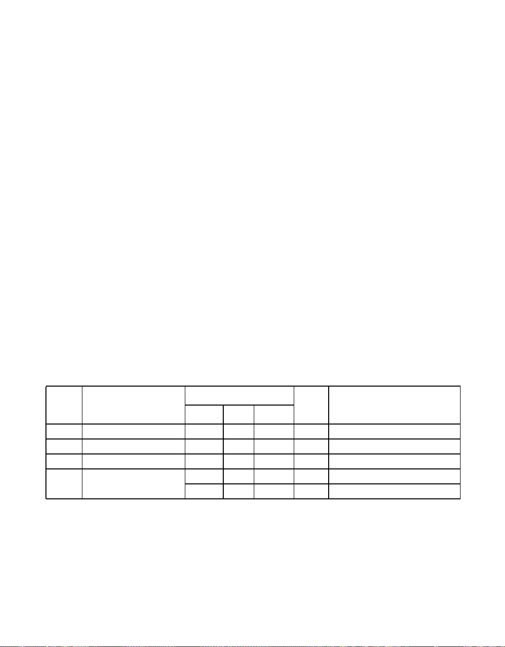
6.5 AC Test Timing Conditions
Unless otherwise noted, all test conditions are as follows:
1. T
=0to+70°C
A
2. VDD= 3.3 V 5%
3. 25 MHz 0.01%
4. REXT = 10K 1%, no load
5. Input conditions:
All Inputs: tr,tf<=10 nS, 20-80%
6. Output Loading
TPO : Same as Figure 11 or equivalent, 10 pF
Open Drain Outputs: 1K Pullup, 50 pF
All Other Digital Outputs: 25 pF
7. Measurement Points:
TPO ,TPI : 0.0 V during data, 0.3V at start/end of
packet
All other inputs and outputs: 1.4 V
6.6 25 MHz Input / Output Clock Timing Characteristics
Refer to Figure 16 for Timing Diagram.
Limit
Sym. Parameter
OSCIN Period 39.996 40 40.004 ns Clock applied to OSCIN
t
1
OSCIN High Time 16 ns Clock applied to OSCIN
t
2
OSCIN Low Time 16 ns Clock applied to OSCIN
t
3
OSCIN to TX_CLK
t
4
Delay
April, 2002 Copyright © 1999-2002 by LSI Logic Corporation. All rights reserved.
Specifications 69 of 88
10 ns 100 Mbps
20 ns 10 Mbps
Unit ConditionsMin Typ Max
Page 70
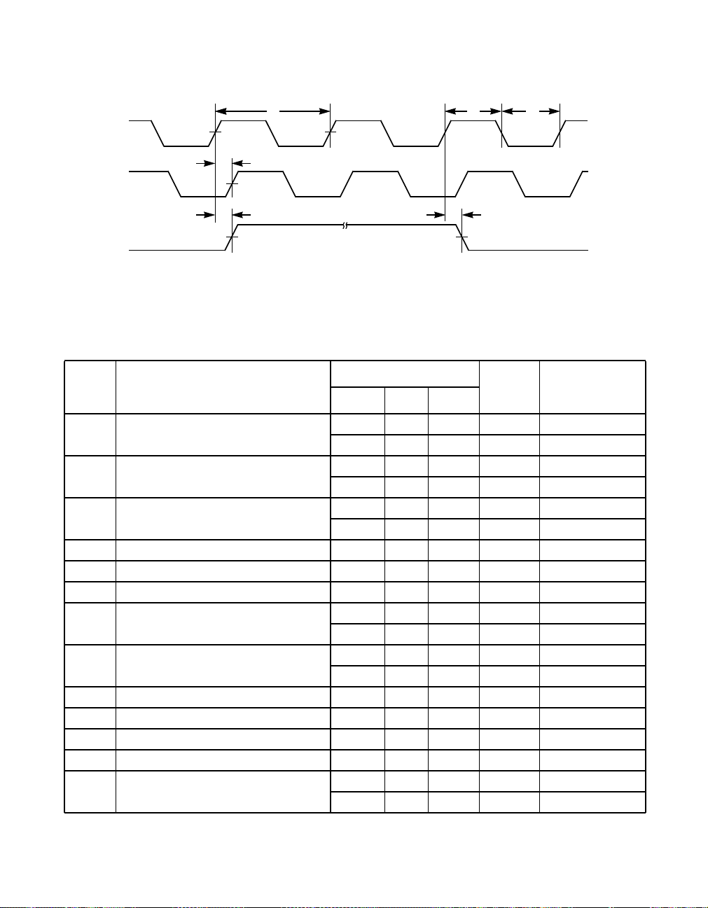
Figure 16 25 MHz Output Timing
t
1
OSCIN
t
4
TX_CLK
(100 MB)
t
TX_CLK
(10 MB)
4
6.7 Transmit Timing Characteristics
Refer to Figure 17 and Figure 18 for Timing Diagram.
Sym. Parameter
TX_CLK Period 39.996 40 40.004 ns 100 Mbps
t
11
399.96 400 400.04 ns 10 Mbps
TX_CLK Low Time 16 20 24 ns 100 Mbps
t
12
160 200 240 ns 10 Mbps
TX_CLK High Time 16 20 24 ns 100 Mbps
t
13
160 200 240 ns 10 Mbps
TX_CLK Rise/Fall Time 10 ns
t
14
TX_EN Setup Time 15 ns Note 1
t
15
TX_EN Hold Time 0 ns
t
16
CRS During Transmit Assert Time 40 ns 100 Mbps
t
17
CRS During Transmit Dessert Time 160 ns 100 Mbps
t
18
TXD Setup Time 15 ns Note 1
t
19
TXD Hold Time 0 ns
t
20
TX_ER Setup Time 15 ns Note 1
t
21
TX_ER Hold Time 0 ns
t
22
Transmit Propagation Delay 60 140 ns 100 Mbps, MII
t
23
Limit
t
2
t
4
t
3
Unit ConditionsMin Typ Max
400 ns 10 Mbps
900 ns 10 Mbps
600 ns 10 Mbps
70 of 88 L80225 10/100 Mbps Ethernet Physical Layer Device - Technical Manual
April, 2002 Copyright © 1999-2002 by LSI Logic Corporation. All rights reserved.
Page 71
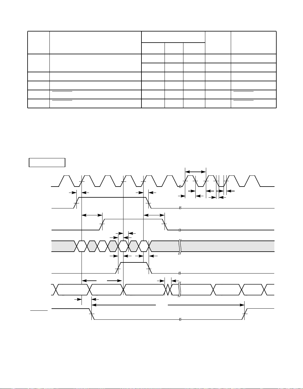
Limit
Sym. Parameter
t
Transmit Output Jitter ±0.7 ns pk-pk 100 Mbps
24
Transmit SOI Pulse Width To 0.3V 250 ns 10 Mbps
t
25
Transmit SOI Pulse Width to 40 mV 4500 ns 10 Mbps
t
26
LA_LED Delay Time 25 ms LA_LED activity
t
27
LA_LED Pulse Width 80 105 ms LA_LED activity
t
28
Note 1: Setup time measured with 5 pF loading on TXC. Additional
leading will create delay on TXC rise time, which will require increased
setup times accordingly.
Figure 17 Transmit Timing - 100 Mbps
MII 100 Mbps
TX_CLK
t
15
TX_EN
t
17
Unit ConditionsMin Typ Max
±5.5 ns pk-pk 10 Mbps
t
11
t
t
16
t
18
13
t
12
t
14
t
14
CRS
t
20
N3
t
22
TXD[3:0]
t
19
N0 N2
N1
t
21
TX_ER
t
24
t
28
TPO
FXO
t
23
±
±
IDLEIDLE /J/K/ DATA /T/R/ IDLE
t
27
LA_LED
Specifications 71 of 88
April, 2002 Copyright © 1999-2002 by LSI Logic Corporation. All rights reserved.
Page 72
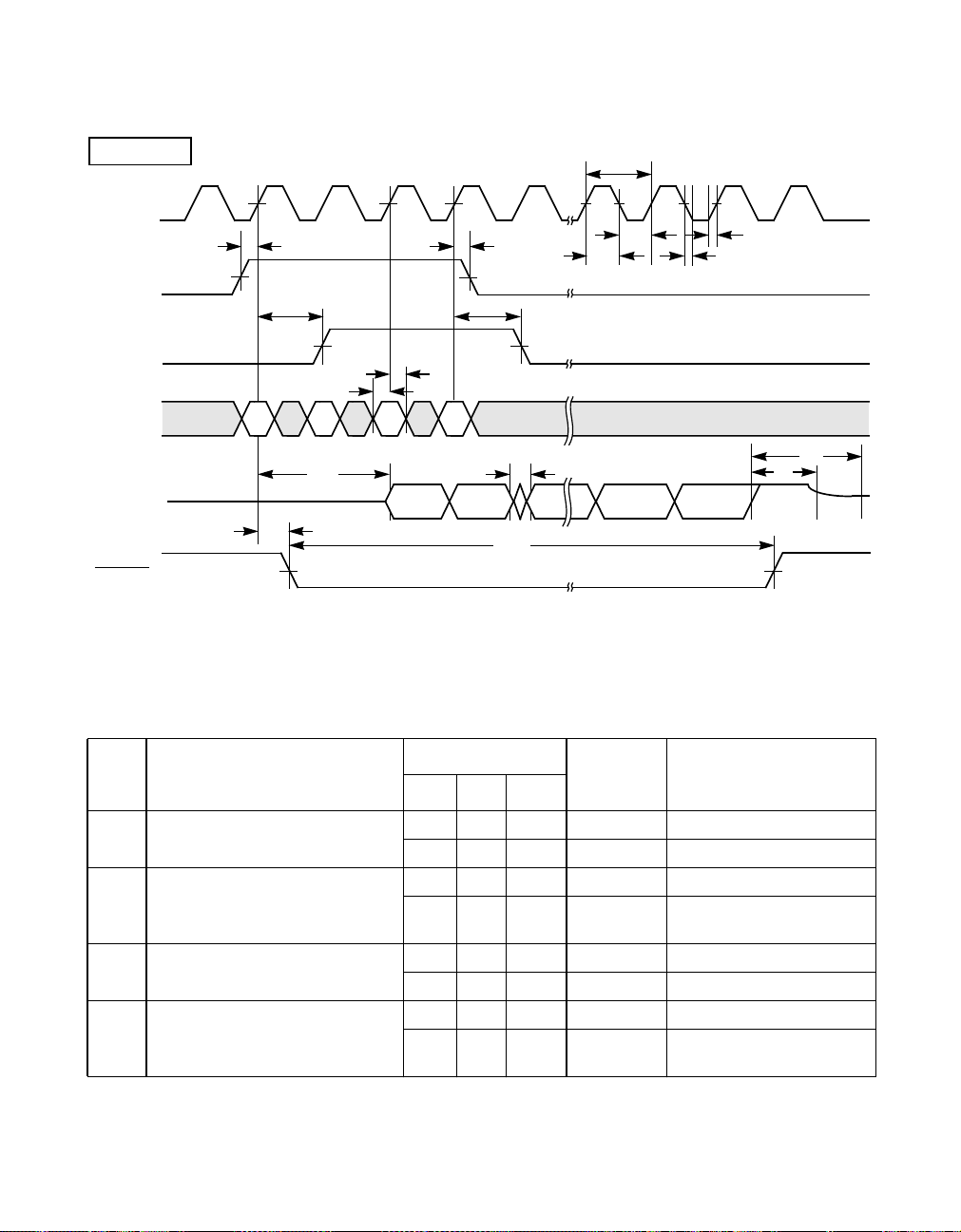
Figure 18 Transmit Timing - 10 Mbps
MII 10 Mbps
TX_CLK
t
15
TX_EN
t
17
CRS
t
20
N3
PREAMBLE PREAMBLE
TXD[3:0]
TPO
t
19
N0 N2
N1
t
23
±
t
27
LA_LED
6.8 Receive Timing Characteristics
t
11
t
t
16
t
18
t
24
13
t
12
t
14
t
14
t
26
t
25
DATA SOIDATA
t
28
Refer to Figure 19 through Figure 23 for Timing Diagrams.
Limit
Sym. Parameter
Start Of Packet To CRS Assert
t
31
Delay
End Of Packet To CRS Dessert
t
32
Delay
Start Of Packet To RX_DV
t
33
Assert Delay
End Of Packet To RX_DV
t
34
Deassert Delay
130 240 ns 100 Mbps, MII
200 ns 100 Mbps, MII
700 ns 10 Mbps
600 ns 10 Mbps. relative to start
240 ns 100 Mbps
3600 ns 10 Mbps
280 ns 100 Mbps
1000 ns 10 Mbps. relative to start
72 of 88 L80225 10/100 Mbps Ethernet Physical Layer Device - Technical Manual
April, 2002 Copyright © 1999-2002 by LSI Logic Corporation. All rights reserved.
Unit ConditionsMin Typ Max
of SOI pulse
of SOI pulse
Page 73

Limit
Sym. Parameter
t
RX_CLK To RX_DV, RXD,
37
RX_ER Delay
RX_CLK High Time 18 20 22 ns 100 Mbps
t
38
RX_CLK Low Time 18 20 22 ns 100 Mbps
t
39
SOI Pulse Minimum Width
t
40
Required for Idle Detection
Receive Input Jitter ±3.0 ns pk – pk 100 Mbps
t
41
LA_LED Delay Time 25 ms LA_LED
t
43
LA_LED Pulse Width 80 105 ms LA_LED
t
44
RX_CLK, RXD, CRC, RX_DV,
t
45
RX_ER Output Rise and Fall
Times
RX_EN Deassert to Rcv MII
t
46
Output HI-Z Delay
RX_EN Assert to Rcv MII Out-
t
47
put Active Delay
Unit ConditionsMin Typ Max
-8 8 ns 100 Mbps
-80 80 ns 10 Mbps
180 200 600 ns 10 Mbps
180 200 600 ns 10 Mbps
125 200 ns 10 Mbps Measure TPI
from last zero cross to
0.3V point.
±13.5 ns pk –pk 10 Mbps
10 ns
40 ns
40 ns
April, 2002 Copyright © 1999-2002 by LSI Logic Corporation. All rights reserved.
Specifications 73 of 88
Page 74
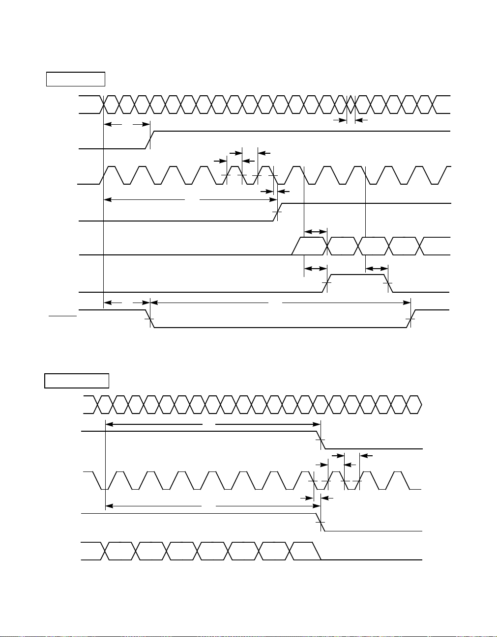
Figure 19 Receive Timing, Start of Packet - 100 Mbps
MII 100 Mbps
TPI
±
CRS
RX_CLK
RX_DV
IDLE J
t
TX TX TX TX TX RX RX RX RX RX RX
DATA DATA DATA DATA DATA DATA DATA DATA DATA DATA DATA
K
DATA DAT A DATA DAT A
31
t
39
t
38
t
t
33
37
DAT A DATA DATA
t
41
t
37
RXD[3:0]
RX_ER
t
43
t
44
LA_LED
Figure 20 Receive Timing, End of Packet - 100 Mbps
MII 100 Mbps
TPI
±
DAT A
T
R
I
FXI
CRS
RX_CLK
RX_DV
±
IIIIIIIIIIIIIIIIII
t
32
RXRX RX RX RX RX RX RX TX TX
t
t
34
37
PREAMBLE PREAMBLE PREAMBLE PREAMBLE PREAMBLE
t
37
t
38
t
37
t
39
RXD[3:0]
DATADATADATADA TADAT ADATADATA
74 of 88 L80225 10/100 Mbps Ethernet Physical Layer Device - Technical Manual
April, 2002 Copyright © 1999-2002 by LSI Logic Corporation. All rights reserved.
Page 75
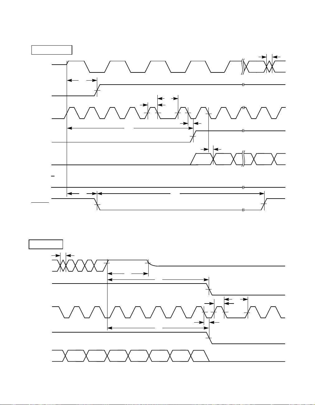
Figure 21 Receive Timing, Start of Packet - 10 Mbps
MII 10 Mbps
TPI
±
t
31
CRS
t
39
t
38
RX_CLK
t
33
RX RX RX RXRX RXTXTXTXTXTX
t
37
RX_DV
RXD[3:0]
RX_ER
t
43
t
44
LA_LED
Figure 22 Receive Timing, End of Packet - 10 Mbps
t
37
PREAMBLE
PREAMBLE
t
DATA DATA
DATA
41
DATA
DATA
MII 10 Mbps
t
41
TPI
DAT A
DAT A
±
DAT A
DAT A
DAT A
SOI
t
40
t
32
CRS
RX_CLK
RX
RX RX RX RX RX RX RX TX TX
t
34
RX_DV
RXD[3:0]
DATADAT A
DATADATADAT A
DATADATA
Specifications 75 of 88
April, 2002 Copyright © 1999-2002 by LSI Logic Corporation. All rights reserved.
t
39
t
38
t
37
Page 76
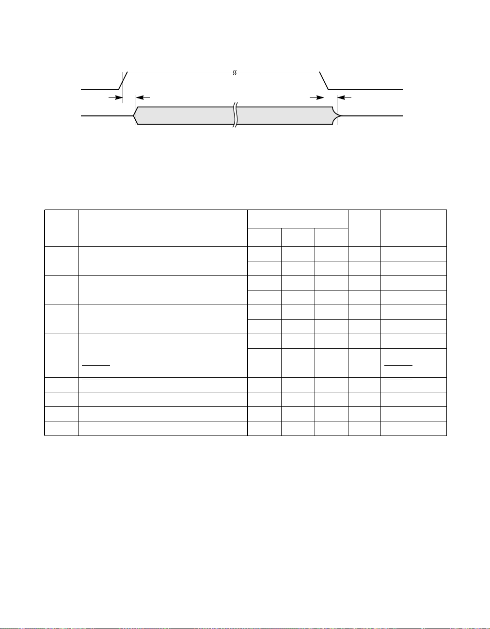
Figure 23 RX_EN Timing
RX_EN
RX_CLK
RXD[3:0]
RX_DV
RX_ER
COL
t
46
6.9 Collision and Jam Timing Characteristics
Refer to Figure 24, Figure 25, and Figure 26 for Timing Diagrams.
Limit
Sym. Parameter
Rcv Packet Start to COL Assert Time 200 ns 100 Mbps
t
51
Rcv Packet Stop to COL Deassert Time 130 240 ns 100 Mbps
t
52
Mt Packet Start to COL Assert Time 200 ns 100 Mbps
t
53
Xmt Packet Stop to COL Deassert Time 240 ns 100 Mbps
t
54
C_LED Delay Time 25 ms C_LED
t
55
C_LED Pulse Time 80 105 ms C_LED
t
56
Collision Test Assert Time 5120 ns
t
57
Collision Test Deassert Time 40 ns
t
58
COL Rise and Fall Time 10 ns
t
60
t
47
Unit ConditionsMin Typ Max
700 ns 10 Mbps
300 ns 10 Mbps
700 ns 10 Mbps
300 ns 10 Mbps
76 of 88 L80225 10/100 Mbps Ethernet Physical Layer Device - Technical Manual
April, 2002 Copyright © 1999-2002 by LSI Logic Corporation. All rights reserved.
Page 77
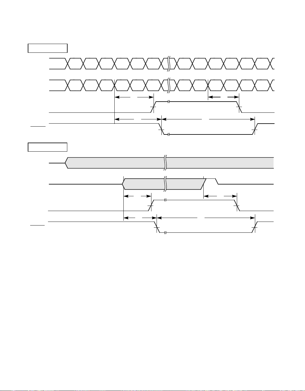
Figure 24 Collision Timing, Receive
MII 100 Mbps
TPO
±
FXO
TPI
I
±
±
I
DATA DATA DAT A DATA DATA DATA DAT A DATA DATA DATA DATA DATA
DATA
I I J K DAT A DATA DATA DATA T R I I
I
COL
C_LED
MII 10 Mbps
TPO
±
TPI
±
COL
C_LED
t
51
t
55
t
51
t
55
t
t
56
t
52
56
t
52
April, 2002 Copyright © 1999-2002 by LSI Logic Corporation. All rights reserved.
Specifications 77 of 88
Page 78
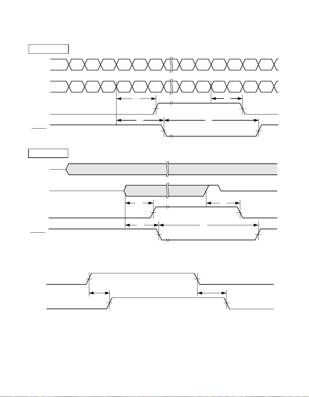
Figure 25 Collision Timing, Transmit
MII 100 Mbps
TPI
±
FXI
±
TPO
±
FXO
±
COL
C_LED
MII 10 Mbps
TPI
±
TPO
±
I
I
DATA DATA DAT A DATA DATA DATA DAT A DA TA DATA DAT A DATA DATA
DATA
I I J K DAT A DATA DAT A DA TA T R I I
I
t
53
t
t
54
t
55
56
t
53
t
54
COL
t
55
t
56
C_LED
Figure 26 Collision Test Timing
TX_EN
t
57
COL
78 of 88 L80225 10/100 Mbps Ethernet Physical Layer Device - Technical Manual
April, 2002 Copyright © 1999-2002 by LSI Logic Corporation. All rights reserved.
t
58
Page 79

6.10 Link Pulse Timing Characteristics
Refer to Figure 27 and Figure 28 for Timing Diagrams.
Limit
Sym. Parameter
NLP Transmit Link Pulse Width See Figure 7 ns
t
61
NLP Transmit Link Pulse Period 8 24 ms
t
62
NLP Receive Link Pulse Width
t
63
Required For Detection
NLP Receive Link Pulse Mini-
t
64
mum Period Required For
Detection
NLP Receive Link Pulse Maxi-
t
65
mum Period Required For
Detection
NLP Receive Link Pulses
t
66
Required To Exit Link Fail State
FLP Transmit Link Pulse Width 100 150 ns
t
67
FLP Transmit Clock Pulse To
t
68
Data Pulse Period
FLP Transmit Clock Pulse To
t
69
Clock Pulse Period
FLP Transmit Link Pulse Burst
t
70
Period
FLP Receive Link Pulse Width
t
71
Required For Detection
FLP Receive Link Pulse Minimum
t
72
Period Required For Clock Pulse
Detection
FLP Receive Link Pulse Maxi-
t
73
mum Period Required For Clock
Pulse Detection
FLP Receive Link Pulse Minimum
t
74
Period Required For Data Pulse
Detection
FLP Receive Link Pulse Maxi-
t
75
mum Period Required For Data
Pulse Detection
FLP Receive Link Pulses
t
76
Required To Detect Valid FLP
Burst
Unit ConditionsMin Typ Max
50 ns
6 7 ms link_test_min
50 150 ms link_test_max
3 3 3 Link
lc_max
Pulses
55.5 62.5 69.5 µs interval_timer
111 125 139 µs
8 22 ms transmit_link_burst_timer
50 ns
525µs flp_test_min_timer
165 185 µs flp_test_max_timer
15 47 µs data_detect_min_timer
78 100 µs data_detect_max_timer
17 17 Link
Pulses
April, 2002 Copyright © 1999-2002 by LSI Logic Corporation. All rights reserved.
Specifications 79 of 88
Page 80
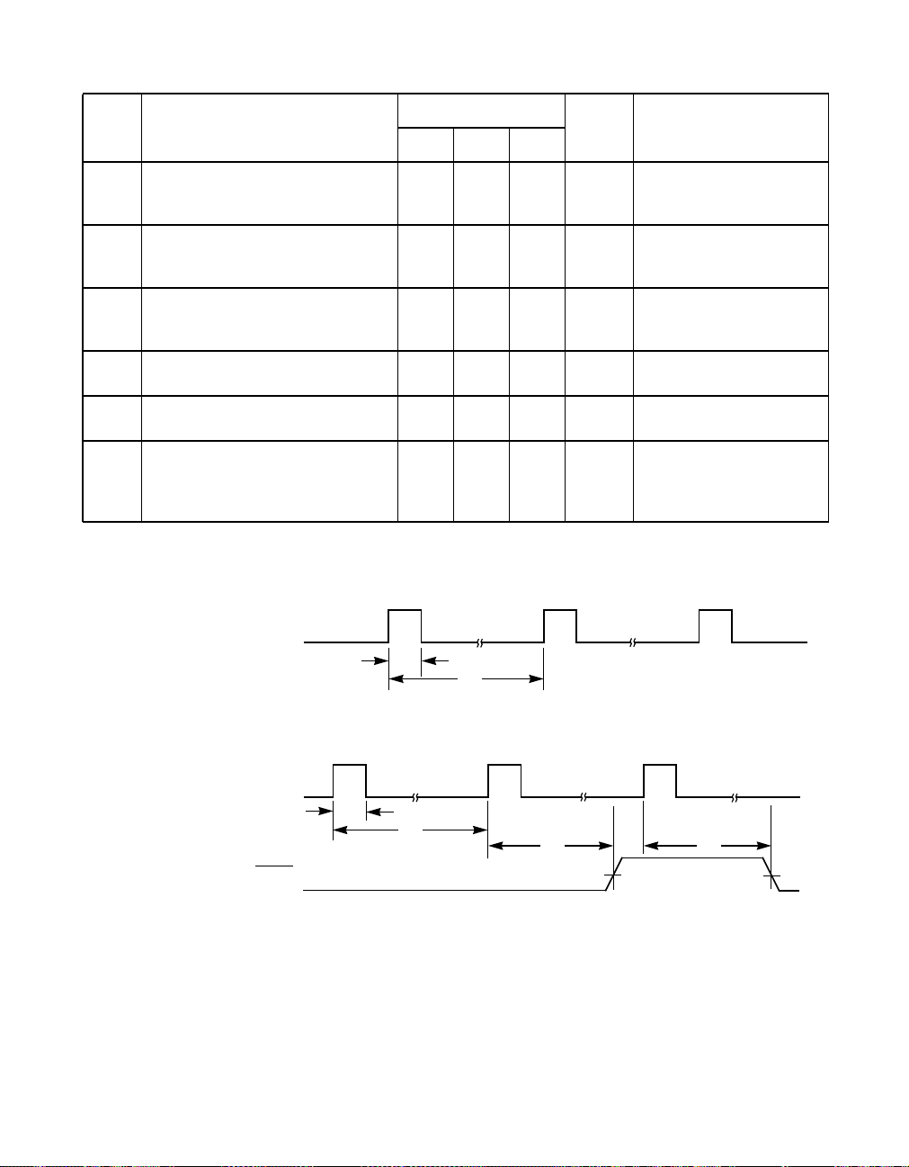
Limit
Sym. Parameter
t
FLP Receive Link Pulse Burst
77
Minimum Period Required For
Detection
FLP Receive Link Pulse Burst
t
78
Maximum Period Required For
Detection
FLP Receive Link Pulses Bursts
t
79
Required To Detect AutoNegotiation Capability
FLP Receive Acknowledge Fail
t
80
Period
FLP Transmit Renegotiate Link
t
81
Fail Period
NLP Receive Link Pulse Maxi-
t
82
mum Period Required For
Detection After FLP Negotiation
Has Completed
Figure 27 NLP Link Pulse Timing
TPO±
Unit ConditionsMin Typ Max
5 7 ms nlp_test_min_timer
50 150 ms nlp_test_max_timer
3 3 3 Link
Pulse
1200 1500 ms
1200 1500 ms break_link_timer
750 1000 ms link_fail_inhibit_timer
a. Transmit NLP
t
61
t
62
b. Receive NLP
TPI±
t
63
PLED
t
64
t
65
t
66
80 of 88 L80225 10/100 Mbps Ethernet Physical Layer Device - Technical Manual
April, 2002 Copyright © 1999-2002 by LSI Logic Corporation. All rights reserved.
Page 81
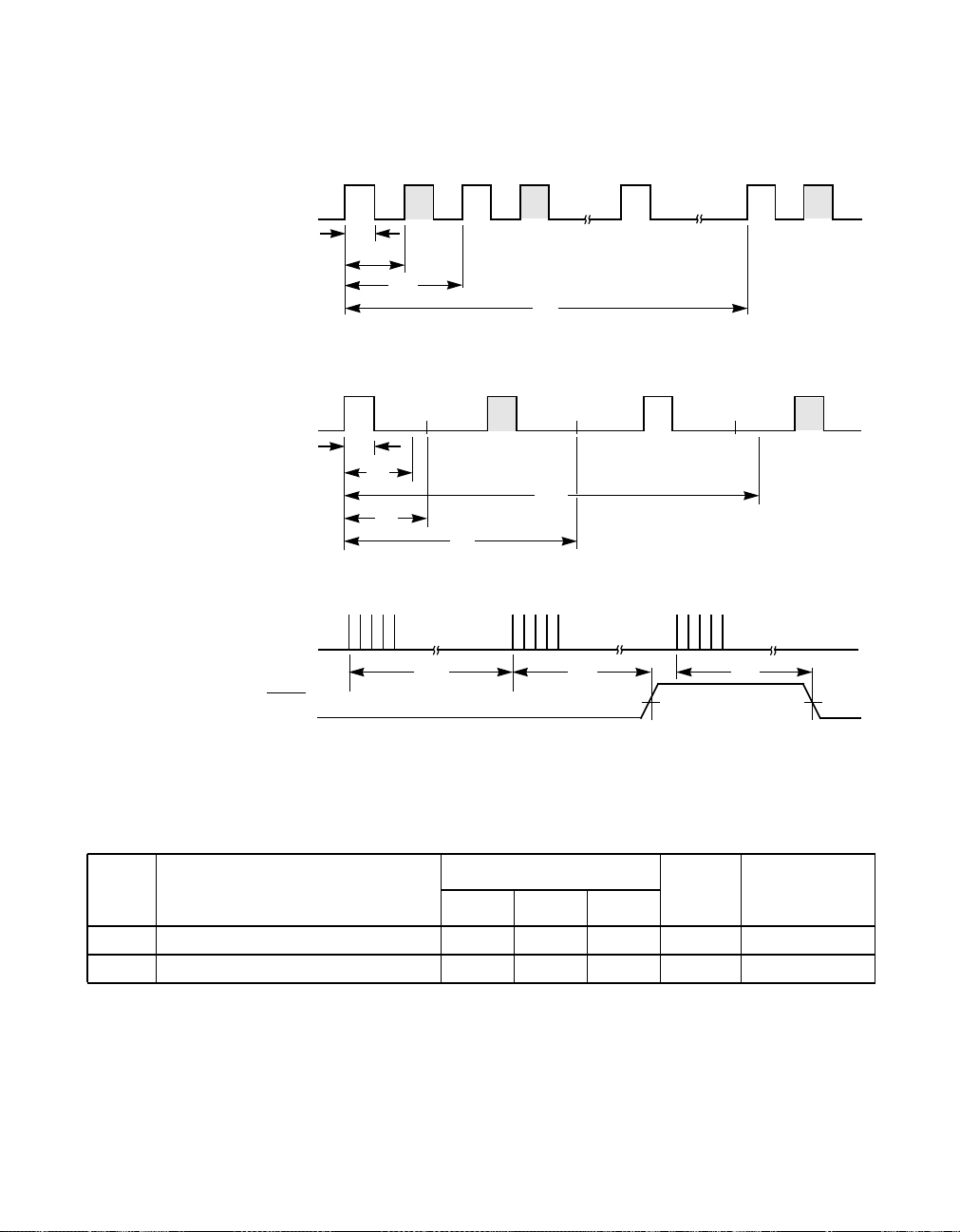
Figure 28 FLP Link Pulse Timing
CLK DATA CLK DATA CLK DATACLK
TPO±
t
67
t
68
CLK DATA CLK DATA
TPI±
a. Transmit FLP and Transmit FLP Burst
t
69
t
70
b. Receive FLP
t
71
t
72
31.25 62.50 125.00 156.25
t
74
t
75
TPI±
t
77
PLED
6.11 Jabber Timing Characteristics
Refer to Figure 29 for Timing Diagram.
Sym. Parameter
Jabber Activation Delay Time 50 100 ms 10 Mbps
t
91
Jabber Deactivation Delay Time 250 750 ms 10 Mbps
t
92
93.75
t
73
c. Receive FLP Burst
t
78
Limit
t
79
Unit ConditionsMin Typ Max
April, 2002 Copyright © 1999-2002 by LSI Logic Corporation. All rights reserved.
Specifications 81 of 88
Page 82
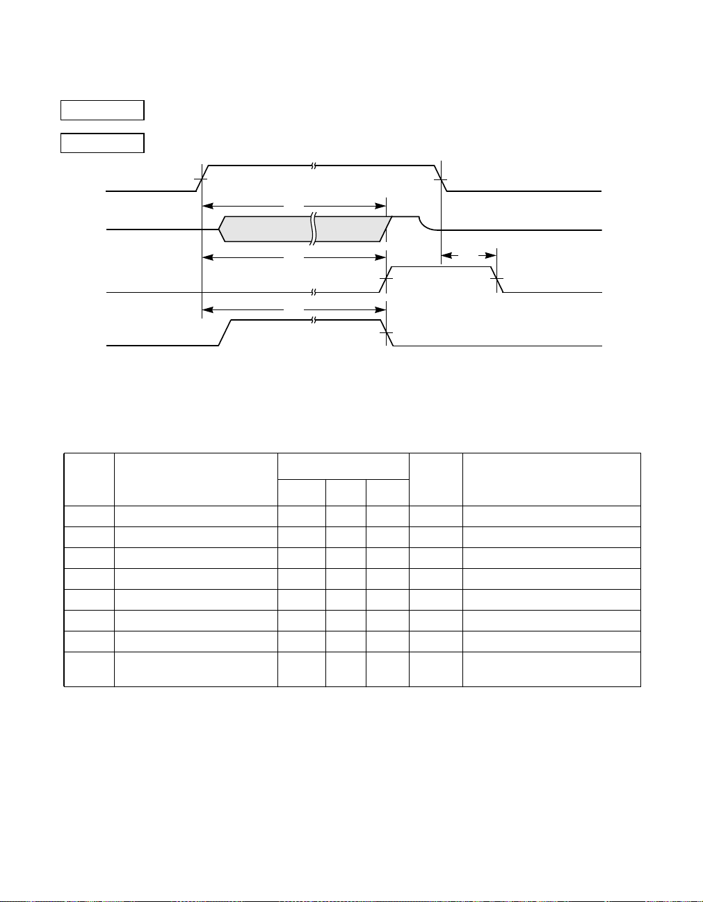
Figure 29 Jabber Timing
MII 100 Mbps
MII 10 Mbps
TXEN
TPO
±
COL
CRS
Not applicable
t
91
t
91
t
91
6.12 MI Serial Port Timing Characteristics
Refer to Figure 30 for Timing Diagrams.
Limit
Sym. Parameter
MDC High Time 20 ns
t
101
MDC Low Time 20 ns
t
102
MDIO Setup Time 10 ns Write Bits
t
103
MDIO Hold Time 10 ns Write Bits
t
104
MDC To MDIO Delay 20 ns Read Bits
t
105
MDIO Hi-Z To Active Delay 20 ns Write-Read bit transition
t
106
MDIO Active To HI-Z Delay 20 ns Read-Write bit transition
t
107
Frame Delimiter (Idle) 32 Clocks # of consecutive MDC clocks
t
108
t
92
Unit ConditionsMin Typ Max
with MDIO=1
82 of 88 L80225 10/100 Mbps Ethernet Physical Layer Device - Technical Manual
April, 2002 Copyright © 1999-2002 by LSI Logic Corporation. All rights reserved.
Page 83
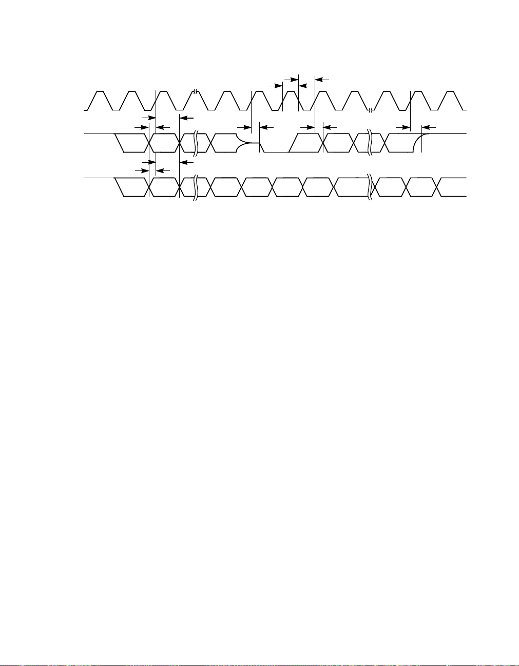
Figure 30 MI Serial Port Timing
MDC
MDIO
(READ)
MDIO
(WRITE)
0
t
103
ST1 ST0
t
103
ST1 ST0
1 13141516173031
t
104
t
104
t
106
REGAD0
REGAD0
t
t
101
t
105
TA0 D15 D14 D0
TA1
TA1 TA0 D15 D1 D0
102
t
107
April, 2002 Copyright © 1999-2002 by LSI Logic Corporation. All rights reserved.
Specifications 83 of 88
Page 84

7 Ordering Information
L 80225
Manufacturer
8 Revision History
1/15/99
• Changed document number to MD4000182/A.
1/25/99
page 5: Pin Description
• Pin # 8; 1 = No Link Detect or Activity, has been changed to 1 = No
Link Detect
page 6: Pin Description
• Pin # 6; Copy change, This pin can drive an LED from both VDD and
GND. has been changed to, This pin can drive an LED from VDD.
• Pin # 6; 0 = Full Duplex, has been changed to, 0 = Full Duplex Mode
Detect with Link Pass
Part Type
100 Base-TX/10 Base-T
Physical Layer Device (PHY)
• Pin # 5; Copy change, ... function of this pin is to be a 10/100 Mbps
Link Detect output... has been changed to...function of this pin is to
be a 10/100 Mbps Detect output..
• Pin # 5; Copy change, This pin can drive an LED from both VDD and
GND. has been changed to, This pin can drive an LED from VDD.
• Pin #5; 0, has been changed to, 0 = 100 Mbit Mode Detected with
Link Pass, 1, has been changed to 1 = 10 Mbit Mode Detected
• Pin # 23; I Pulldown has been changed to I.
84 of 88 L80225 10/100 Mbps Ethernet Physical Layer Device - Technical Manual
April, 2002 Copyright © 1999-2002 by LSI Logic Corporation. All rights reserved.
Page 85

page 7: Pin Description
• Pin #40: ANEG Speed Duplx modes, 1 1 0 Mode Description has
been replaced with 111ModeDescription , Mode 1 1 1 Description
has been replaced with 1 1 0 Mode Description.
page 8: Figure 1. Block Diagram
• Reference to MDA4 has been deleted
• Reference to VDD[6:1] has been changed to VDD[4:1].
page 29: Section 3.14.1, “General.”
• Paragraph #3 has been deleted.
page 31: Section 3.14.9, “Link Indication.”
• Paragraph #1 copy change, ...transistors in addition to a weak pullup
resistor, so it can drive... has been changed to ...transistors in
addition to a weak pullup resistor. Since this LED is shared with...
page 34: Section 3.17.3, “Full Duplex Indication.”
• Paragraph #1 copy change, ...transistors and a weak pullup resistor,
so it can drive... has been changed to...transistors and a weak pullup
resistor. Since these two LEDs also share their outputs with the
address inputs, they should be driven only from Vdd.
page 36: Section 3.22, “LED Drivers.”
• Paragraph #1 copy change, ...pullup and pulldown driver transistors
with a pullup resistor so... has been changed to ... pullup and
pulldown driver transistors. Since these two LEDs also share their
outputs with the address inputs, they should be driven only from Vdd.
• Table 3. LED Event Definition: deleted XMT ACT and RCV ACT.
page 50: Table 12 MI Register 18 (Status Output) Structure and Bit
Definition
• Table 12 has been added to the Data Sheet
page 56: Table 14 TP Transformer Sources
• Vendor BEL, Part Number is now, S558-5999-J9, 558-5999-46
April, 2002 Copyright © 1999-2002 by LSI Logic Corporation. All rights reserved.
Revision History 85 of 88
Page 86

• Vendor HALO, Part Number is now, TG22-3506ND, TG110-S050N2
• Vendor PCA, Part Number is now, EPF8017GH
• Note: H1089, S558-5999-46, EPF8017GH, and TG22-3506ND are
pin compatible. Please contact the transformer vendor for additional
information... has been added.
page 57: Section 5.6.2, “Clocks.”
• Paragraph #2 copy change, ... optional 50K resistor to GND. LA_LED
should always be tied through a 50K resistor to GND since it has
both pullup and pulldown capability. .... has been changed to ....
optional 50K resistor to GND. FD_LED & L_LED should always be
tied through a 50K resistor to GND since they have both pullup and
pulldown capability.
page 63: Section 5.10, “LED Drivers.”
• Paragraph #1 sentence ... In addition, FD_LED ... as well as VDD.
..has been deleted. Paragraph #3 has been deleted.
4/2002
• Changed document number to MD4000182/B.
• Reformatted document with a standard LSI template.
• All references to SEEQ have been removed.
• All “80225” were changed to “L80225.”
• Renumbered Tables 7 thru 12a to Tables 6 thru 12. (Table sequence
skipped a number in previous version of document, because Table 6
had been deleted.)
• Renumbered Section 5.7.3 (Serial Port Addressing) to Section 5.7.2.
(Numbering sequence in previous version of document was incorrect
- 5.7.1 followed by 5.7.3.)
• Renumbered Section 5.8.4 (Serial Port Addressing) to Section 5.8.2.
(Numbering sequence in previous version of document was incorrect
- 5.8.1 followed by 5.8.4.)
• Renumbered Figures 28 thru 31 to Figures 27 thru 30. (There was
no Figure 27 in previous version of document.)
• Updated all section, table, and figure cross-references throughout
the document.
86 of 88 L80225 10/100 Mbps Ethernet Physical Layer Device - Technical Manual
April, 2002 Copyright © 1999-2002 by LSI Logic Corporation. All rights reserved.
Page 87
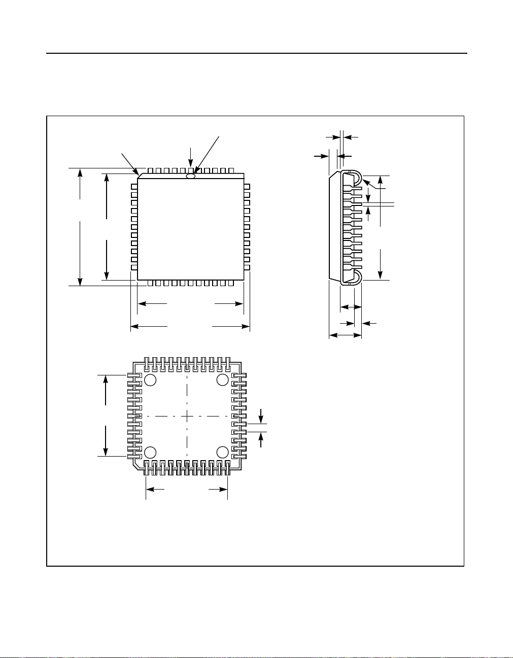
9 Surface Mount Packages
Figure 31 44-Pin Plastic Leaded Chip Carrier
.695 (17.65)
.685 (17.40)
.656 (16.66)
.650 (16.51)
.500 (12.70)
.048 (1.22) x 45˚
.042 (1.07) x 45˚
Ref.
Pin No. 1 Identifier
Pin No. 1
L80225
.656 (16.66)
.650 (16.51)
.695 (17.65)
.685 (17.40)
.0103 (.261)
.0097 (.246)
.056 (1.42)
.042 (1.07)
R .045 (1.14)
R .025 (.64)
.021 (0.53)
.013 (0.33)
.630 (16.00)
.590 (14.99)
.112 (2.84)
.100 (2.54)
.020 (0.51) min.
.180 (4.57)
.165 (4.19)
.050 (1.27)
BSC
.500 (12.70)
Ref.
Note:
1. All dimensions are in inches and in (millimeters).
2. Dimensions do not include mold flash. Maximum allowable flash is .008 (.20).
3. Formed leads shall be planar with respect to one another within 0.004 inches.
Important: This drawing may not be the latest version.
Surface Mount Packages 87 of 88
April, 2002 Copyright © 1999-2002 by LSI Logic Corporation. All rights reserved.
Page 88

Headquarters
Doc. No. MD400182/B
LSI Logic Corporation
North American Headquarters
Milpitas CA
Tel: 408.433.8000
Fax: 408.433.8989
LSI Logic Europe Ltd
European Headquarters
Bracknell England
Tel: 44.1344.426544
Fax: 44.1344.481039
Visit us at our web site: http://www.lsilogic.com
ISO 9000 Certified
The LSI Logic logo design is a registered trademark of LSI
Logic Corporation. All other brand and product names may
be trademarks of their respective companies.
LSI Logic K.K.
Headquarters
Tokyo Japan
Tel: 81.3.5463.7821
Fax: 81.3.5463.7820
LSI Logic Corporation reserves the right to make changes
to any products and services herein at any time without
notice. LSI Logic does not assume any responsibility or liability arising out of the application or use of any product or
service described herein, except as expressly agreed to in
writing by LSI Logic; nor does the purchase, lease, or use
of a product or service from LSI Logic convey a license
underany patent rights,copyrights,trademarkrights, or any
other of the intellectual property rights of LSI Logic or of
third parties.
April, 2002 Copyright © 1999-2002 by LSI Logic Corporation. All rights reserved.
Surface Mount Packages
 Loading...