

Page 1
Cod. MW6165
R-Log
Quick Start
Update 01/25/2016
Page 2
R-Log – Quick Start
Cod. INSTUM_00953
Pag. 2
Summary
1. Introduction .................................................................................................................................. 3
2. To start… ..................................................................................................................................... 3
3. First installation ........................................................................................................................... 3
3.1. Installing the software on your PC....................................................................................... 6
3.1.1. Installation procedure................................................................................................... 6
3.1.2. 3DOM Software ........................................................................................................... 6
3.2. Datalogger configuration ..................................................................................................... 7
3.2.1. Starting the instrument ................................................................................................. 7
3.2.2. Auto- recognition of the connected probes .................................................................. 8
3.2.3. Adding the new instrument to 3DOM program ........................................................... 8
3.2.4. Checking the instrument internal clock ....................................................................... 9
3.2.5. Instrument configuration .............................................................................................. 9
3.3. Creating a configuration report .......................................................................................... 14
3.4. Connecting the probes........................................................................................................ 14
3.4.1. Electrical connection .................................................................................................. 14
3.5. Displaying measures in fast acquisition mode ................................................................... 16
3.6. Starting the system and displaying measurements............................................................. 16
4. Elaborated data storage options ................................................................................................. 17
4.1. Storing data in a text file .................................................................................................... 17
4.2. Saving data on a Gidas database ........................................................................................ 17
5. Receiving elaborated data .......................................................................................................... 20
6. Displaying elaborated data ......................................................................................................... 20
Copyright 2010-2016 LSI LASTEM. All rights reserved.
This manual can be modified without notice.
Anybody can copy, print or publish this manual without LSI LASTEM written authorization.
LSI LASTEM reserves the right to modify the product without an immediate revision of this document.
Page 3
R-Log – Quick Start
Cod. INSTUM_00953
Pag. 3
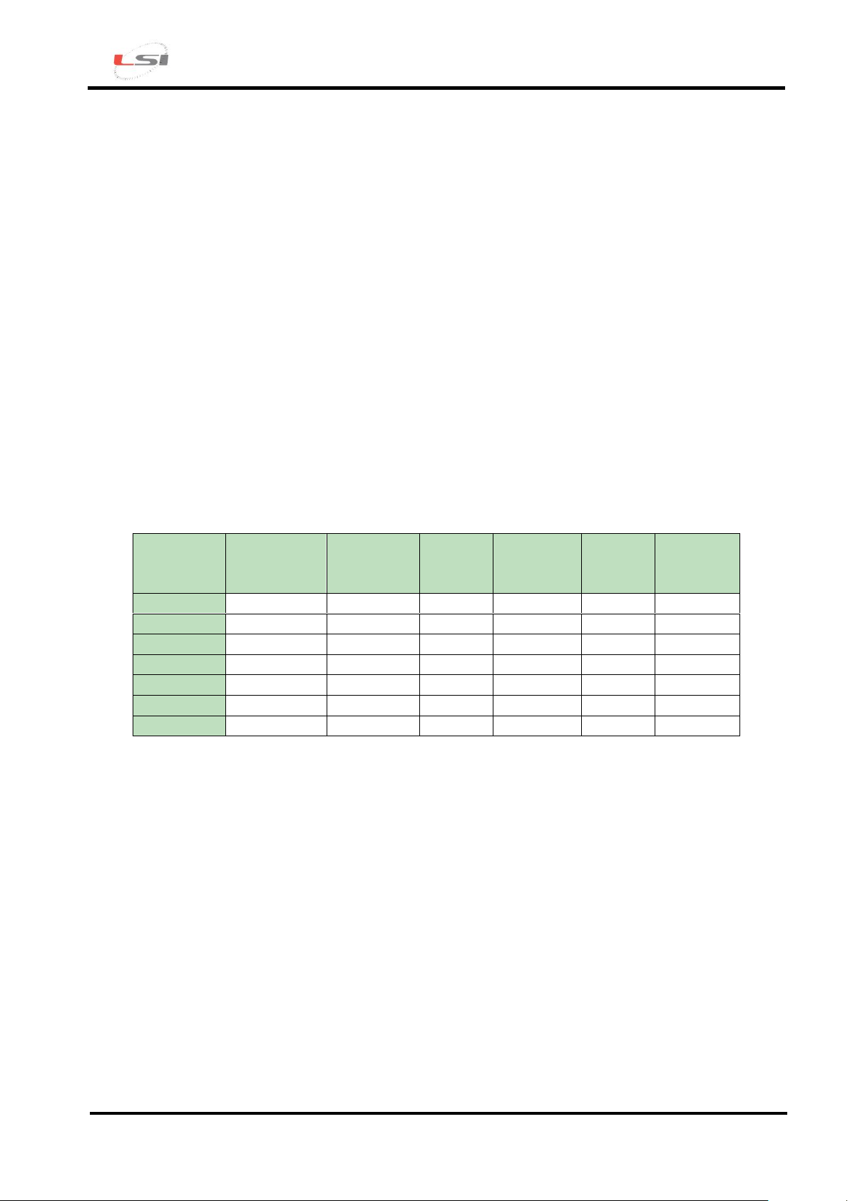
Model
Connector
inputs
Terminal
board
inputs
Master
mode
Repeater
mode
Slave
mode
Ethernet
output
ELR510M
X
- X - - -
ELR510R
X - - X -
-
ELR510S
X - - - X
-
ELR515M
-
X X - - -
ELR515R
- X - X -
-
ELR515S
- X - - X
-
ELR516M
- X X - -
X
1. Introduction
This manual is an introduction to the use of the R-Log datalogger.
Reading this manual will allow you to perform the basic operations for starting this device.
Refer to GidasTea – User manual (code SWUM_00662) and particularly to the Step-by-step Guide
accessible from ? menu of GidasTEA program for applications requiring the calculation of
microclimate indexes.
For special applications, such as - for example – the use of specific communication devices (modem,
communicators, Ethernet/RS232 converters etc.) or where the implementation of actuation logics or
the setup of calculated measurements is requested, please refer to the R-Log and 3DOM software
User Manuals, that are included in the MW6501 - LSI LASTEM Products DVD in the Manuals –
DOCUMENTS section.
2. To start…
There are the following models of R-Log:
Additionally, R-Log is compatible with the following sensors provided with radio communication
(S-Log):
The instrument model is indicated on the label located on the back of the instrument and in the
information displayed by the datalogger during the first boot phases (§3.2.1).
3. First installation
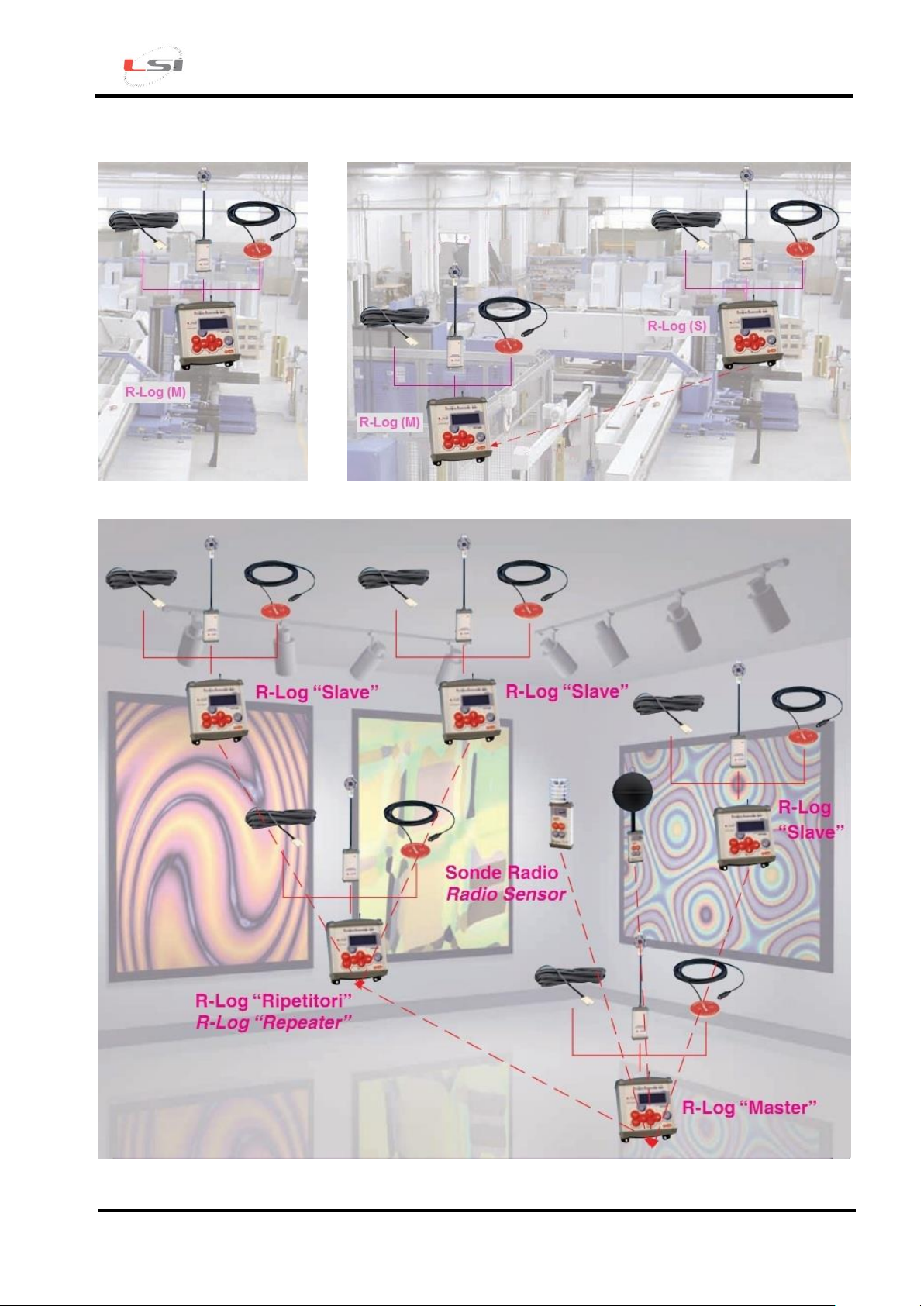
Basic operations for turning the instrument on depend on the installation typology to be
implemented: from the simplest, consisting of a single Master datalogger (Fig. 1), to the more
complex, consisting of a Master instrument and of one or more Slave/Repeater devices (Fig. 2 and
Fig. 3).
o ELR200: environment sensors for temperature/ relative humidity;
o ELR205: black globe and wet bulb temperature sensors;
o ELR210: 2- temperature contact sensor.
Page 4
R-Log – Quick Start
Cod. INSTUM_00953
Pag. 4
Fig. 1 – A-type installation.
Fig. 2 – B- type installation.
Legenda: ________: cable connection; _ _ _ _ _ _: radio connection.
Fig. 3 – C-type installation.
Page 5
R-Log – Quick Start
Cod. INSTUM_00953
Pag. 5
For A-type installation: only one 16M R-Log (ELR515M or ELR5 models)
Installation of 3DOM software on PC;
Datalogger configuration with 3DOM software;
Creation of a Configuration Report;
Connection of the probes to the datalogger;
Display of measurements in fast acquisition mode.
For A-type installation: only one R-Log (ELR510M model)
Installation of 3DOM software on PC;
Connection of probes to the datalogger for auto-recognition;
Transfer to 3DOM software of the new configuration generated on the datalogger;
Display of measurements in fast acquisition mode.
For B or C-type installation: one R-Log (ELR515M or ELR516M models) and one or more
ELR515S R-LOG Slave and EL515R Repeater
Installation of 3DOM software on PC;
Configuration of each Slave/Repeater datalogger with 3DOM software;
Configuration of the Master datalogger with measurements imported by Slave/Repeater
devices;
Generation of a Configuration Report for each datalogger;
Connection of probes to their dataloggers;
Measurement display in fast acquisition mode on each datalogger;
System boot-up and display of all measurements.
For B or C-type installation: one ELR510M-model R-Log and one or more ELR510S Slave RLOG and ELR510R Repeater
Installation of 3DOM software on PC;
Connection of probes to their dataloggers for auto-recognition;
Transfer to 3DOM software of the new configuration generated on dataloggers;
Configuration of the Master datalogger with measurements imported by Slave/Repeater
devices;
Measurements display in fast acquisition mode on each datalogger;
System boot-up and display of all measurements.
Afterwards it will be possible to configure the software for data storage in different formats (text,
SQL database and others).
Page 6
R-Log – Quick Start
Cod. INSTUM_00953
Pag. 6
Push button selector
Main menu push button
Configuration list of
selected instrument
Data storage
supports list
Configured
instruments list
Properties of selected instrument
Last updated status of
selected instrument
3.1. Installing the software on your PC
To configure your datalogger, you only have to install 3DOM on a PC. However, if this PC is the
one that will be used for data management, it is recommended to contextually install all the other
software as well along with their licenses of use.
3.1.1. Installation procedure
To install the program, proceed as follows:
Introduce MW6501 - LSI LASTEM Products DVD in the DVD reader of your PC;
Select Information-Installation in the SOFTWARE section;
Follow the instructions indicated under Guided Installation of LSI LASTEM programs
paragraph.
3.1.2. 3DOM Software
Through 3DOM software, you can perform the instrument configuration, change the system
date/time and download stored data by saving them in one or more formats.
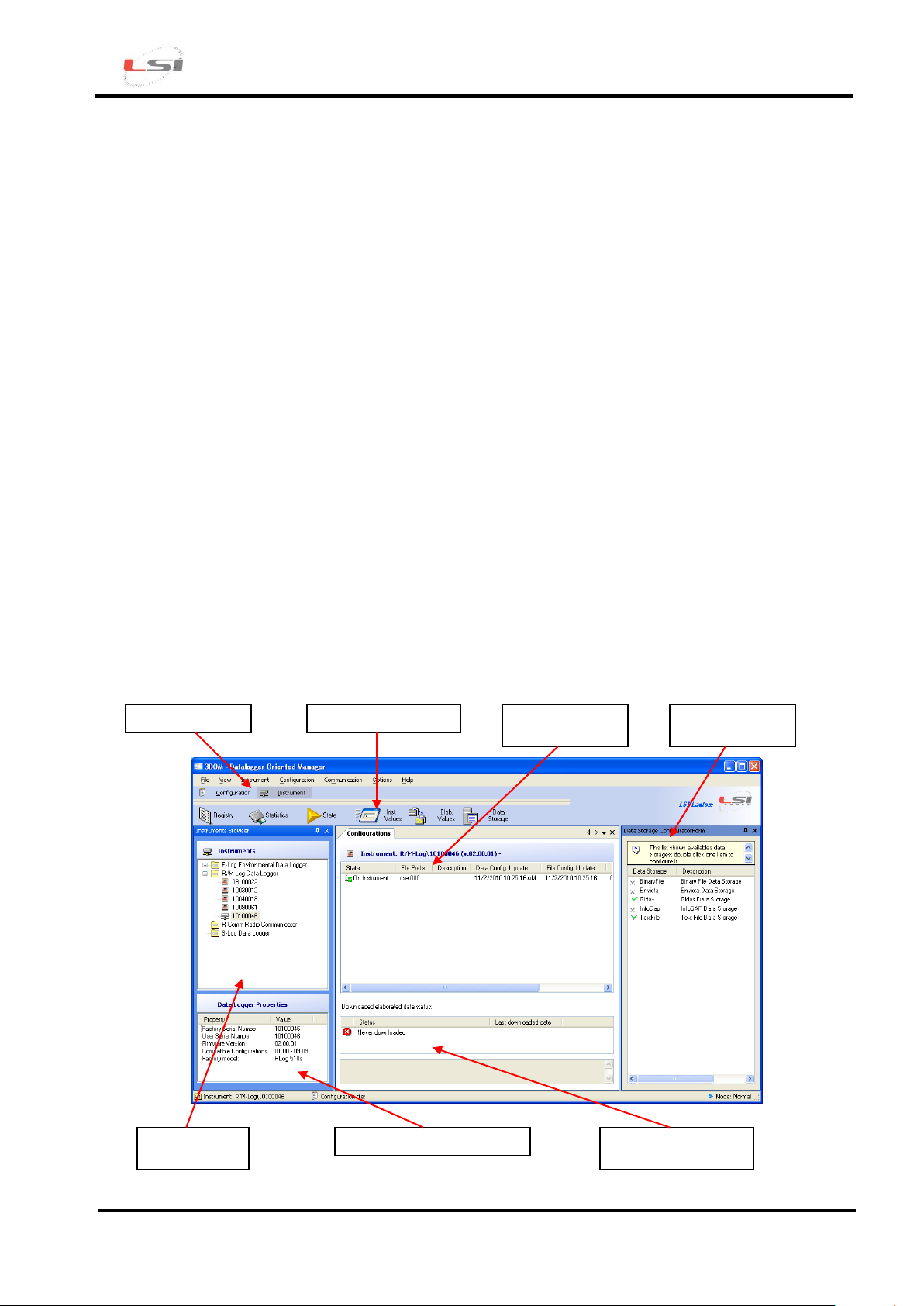
At the end of the installation procedure, start 3DOM program from LSI LASTEM programs list. The
aspect of the main window is as below:
.
Page 7
R-Log – Quick Start
Cod. INSTUM_00953
Pag. 7
3DOM program uses the Italian language in case of Italian version of the operating system; in case
of a different language of the operating system, the program 3DOM uses the English language. To
force the use of the Italian or the English language, whatever may be the language used by the
operating system, the file “C:\Programmi\LSILastem\3DOM\bin\3Dom.exe.config” will have to be
opened with a text editor (for ex. Notepad) and change the value of the attribute UserDefinedCulture
by setting en-us for English and it-it for Italian. Below is an example of setting for the English
language:
<setting name="UserDefinedCulture" serializeAs="String">
<value>en-us</value>
</setting>
3.2. Datalogger configuration
Per procedere alla configurazione di uno o più datalogger è necessario eseguire, per ciascuno
strumento, le indicazioni di seguito riportate.
For ERL515M, ERL516M, ELR515S and ELR515R models:
Start the instrument;
Insert the instrument in 3DOM;
Check the instrument’s internal clock;
Create the configuration in 3DOM;
Send the configuration settings to the instrument.
For ELR510M, ELR510S and ELR510R models:
Connect all probes to the instrument inputs;
Start the instrument;
Perform probe auto-recognition;
Insert instrument and set its configuration on 3DOM;
Check the instrument’s internal clock;
Modify the configuration in 3DOM;
Send the configuration settings to the instrument.
3.2.1. Starting the instrument
R-Log is provided with a rechargeable internal battery. All models can also be powered through an
external 8 ÷ 14 Vcc (BSC015) power-supply, by means of the connector located on the instrument
top panel; in this case the positive pole is the one inside the connector.Ensure not to invert the power
supply polarity, even if the instrument is protected against this incorrect operation.
ELR515M, ELR515R, ELR515S and ELR516M models can also be power supplied through the
terminal board. Refer to the following table for connection to the instrument input terminals and to
sensors or electricity-powered devices output terminals.
Page 8
R-Log – Quick Start
Cod. INSTUM_00953
Pag. 8
Power supply
12V
Model
Signal
Terminal
ELR515M-R-S
ELR516M
0 Vdc
28 or 29
+ Vdc
30 or 31
GND
32
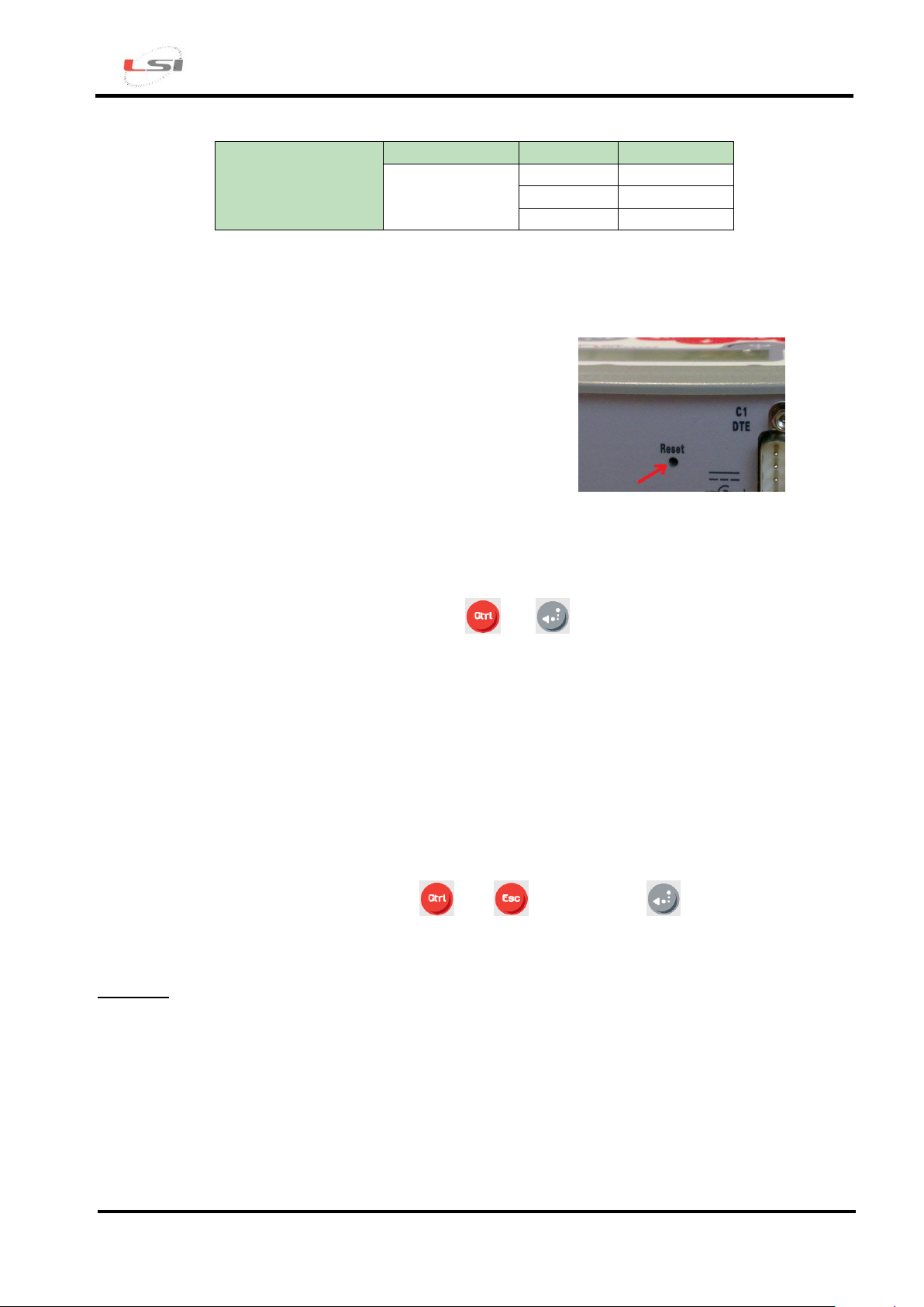
In case of failure to turn the instrument on, press the RESET
key inside the hole placed on the instrument top panel through
a pointed object (such as a straightened paper clip) and try
again the button combination to turn the instrument on; if this
remains turned-off, please contact LSI LASTEM.
It is recommended, where available, to connect the GND wire (ground wire) to terminal 32.
Before using the instruments, it is advisable to keep them under load for at least 8 hours.
ATTENTION: in case terminals 5-6 and 16-17 are used to power supply any external devices, these
must be provided with a protection circuit against short-circuits or against adsorption currents higher
than 1 A.
Start the instrument by pressing simultaneously and buttons on the R-Log front panel.
The datalogger will display the product presentation window that will remain on the screen for about
10 seconds; when the window disappears, the survey will be automatically started based on the last
configuration stored before the instrument shutdown. Refer to §3.2.4 if the system asks to set the
clock.
3.2.2. Auto- recognition of the connected probes
This function is only available for ELR510 models.
After sensors have been physically connected, the instrument can be configured for auto-recognition
of the probes by simultaneously pressing and buttons; press button to confirm the
operation. At the end of the auto-recognition function, a new survey will be started and the instant
values window will be automatically displayed.
Attention! This operation will cancel all data stored in memory; if you wish to save stored data,
proceed to download data from your PC before confirming the auto-recognition. Additionally, all
measurements performed by the connected probes will be reset to default values.
3.2.3. Adding the new instrument to 3DOM program
Connect your PC to serial port 1 through the supplied ELA105 serial cable. Start 3DOM program
from the LSI LASTEM programs list, select Instrument-> New…and follow the guided procedure.
Set as communication parameters:
Page 9
R-Log – Quick Start
Cod. INSTUM_00953
Pag. 9
Type of communication: Serial;
Serial port: <indicate the PC port connected with ELA105 serial cable >;
Bps speed: 57600;
Once the instrument has been recognized, additional data can be entered, such as User-defined name
and Description.
Once the data entry procedure has been completed, the program tries to download the calibration
data and the factory setup of the device; in the event the communication fails to terminate this
operation, it will be impossible to change or create new configurations. At the end of the procedure,
the serial number of your instrument will be displayed in the Instruments panel.
3.2.4. Checking the instrument internal clock
A few seconds after turning the instrument on, it might ask you to reset its internal clock (date and
time). This happens only in particular conditions, for example when the battery is completely
discharged; in this case, the setting of date/time is mandatory and cannot be cancelled.
In order to have accurate time data, the datalogger internal clock should be correct. Failing this, the
clock can be synchronized with that of your computer through the 3DOM software (Statistics…
function in Communication menu) or change it directly in the date/time window using the following
buttons:
: accesses change mode; exits change mode confirming and storing the new date/time;
: exits change mode discarding any changed values;
: moves the cursor to the field to be changed;
: increments the value selected by the cursor; other date/time elements can be
contextually changed;
: decrements the value selected by the cursor; other date/time elements can be
contextually changed.
3.2.5. Instrument configuration
If not expressly requested by the customer, the instrument comes from the factory with a standard
configuration. This needs to be changed by adding the measurements of the sensors to be acquired.
In brief, these are the operations to be performed:
Create a new configuration (ELR510 models excluded);
Add the measurements of the sensors to be connected to the terminal board (ELR510 models
excluded);
Page 10
R-Log – Quick Start
Cod. INSTUM_00953
Pag. 10
Add any measurements of the sensors to be connected to the serial port or to be acquired via
radio;
Set the elaboration rate;
Set actuation logics (optional);
Set the instrument operating characteristics (optional);
Set radio communication parameters;
Import the measurements of any Slave/Repeater devices (only for R-Log Master);
Save the configuration and transfer it to the datalogger.
CREATING A NEW CONFIGURATION (ELR510 models excluded)
Once the new instrument has been successfully added to 3DOM, the datalogger basic configuration
should appear in the Configurations panel (named user000 by default). It is recommended not to
change this configuration as, in the event of problems, it could be necessary to reset the instrument
by providing this very configuration.
It is recommended to create a new configuration starting from the basic one or from one of the
available models. In the first case, proceed as follows:
Start the 3DOM program from the LSI LASTEM program list;
Select your instrument serial number in the Instruments panel;
Select the name of the basic configuration in the Configurations panel (user000 by default);
Press the selected name with the right key of your mouse and choose Save as New
Configuration…;
Give a name to the configuration and press OK.
In the second, on the contrary:
Start the 3DOM program from the LSI LASTEM program list;
Select your instrument serial number in the Instruments panel;
Select New… from the Configuration menu;
Select the desired configuration model and press OK;
Give a name to the configuration and press OK.
Once the operation completed, the name of the new configuration will appear in the Configurations
panel.
For each instrument, more configurations can be created. The current configuration, indicated in the
configurations panel by the icon , is the last one sent to the instrument.
ENTERING SENSORS MEASURES
The auto-recognition of the connected probes function (available only for ELR515 and ELR516
models) provides to configure the instrument with the measures of the probes connected to its inputs.
It should not be necessary to configure other measures unless they are derived measures or serial
sensors.
Page 11
R-Log – Quick Start
Cod. INSTUM_00953
Pag. 11
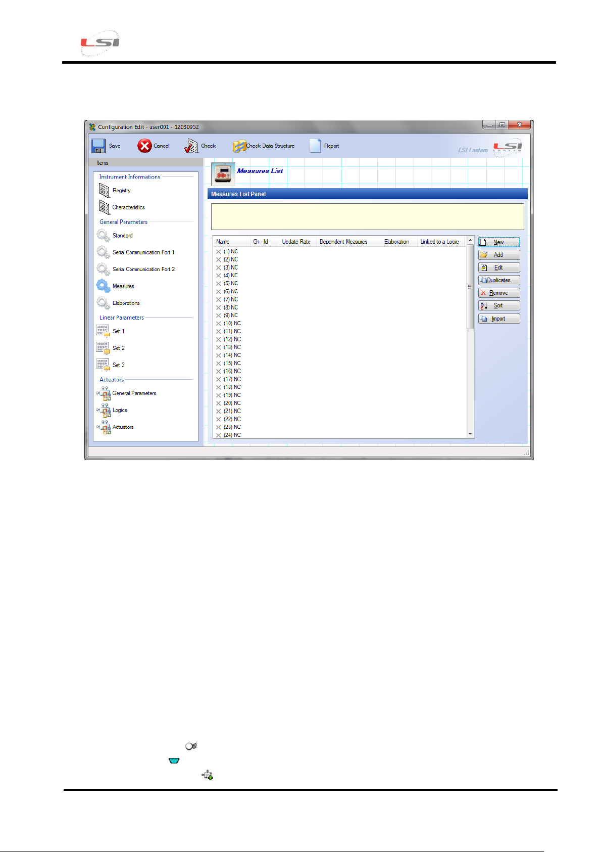
Select the item Measures from the section General Parameters to display the panel containing the
measures management parameters.
3DOM contains a registry of LSI LASTEM sensors where each sensor is suitably configured to be
acquired by R-Log. If the sensor was provided by LSI LASTEM, simply press the Add button, carry
out the sensor research by setting the sensor commercial code or by searching it in its category and
press the OK button. The program automatically determines the most suitable input channel
(selecting it among the available ones) and enters the measures in the Measures List Panel.
On the contrary, if the sensor is not LSI LASTEM or doesn’t appear in the 3DOM sensors registry,
or you want to connect it to the datalogger in single ended mode (in this case refer to the instrument
user manual), press the New button to add a measure, entering all the parameters requested by the
program (name, measure unit, elaborations etc.). For more details on the addition of new measures,
refer to the program manual and to the on-line guide that generally appears during the change of
each programmable parameter.
These operations should be repeated for each sensor that is to be acquired by the instrument.
Once the measures addition phase completed, the Measures List Panel shows the list of all the
configured measures. For each measure, the list shows position, name, channel, acquisition rate,
associated elaboration types. According to the type of measurement, a different icon is displayed:
Acquired sensor: ;
Serial sensor: both the channel and the network address are displayed (protocol ID);
Calculated measure: .
Page 12
R-Log – Quick Start
Cod. INSTUM_00953
Pag. 12
Besides, if a measure is used by a derived quantity, the icon changes: , , .
The measures order can be changed according to your requirements by pressing the Sort button. It is
however advisable to keep coupled the quantities that need to be acquired together (for ex.: wind
speed and direction) and give priority to the measures with a fast acquisition rate, moving them on
top of the list.
SETTING THE ELABORATION RATE
The elaboration rate is 10 minutes by default. If you wish to change this parameter, select
Elaborations from the General Parameters section.
SETTING THE ACTUATION LOGIC
The instrument has 2 actuators that can be used for the power supply of the sensors connected to the
terminal board. Actuators can be also used by programmable actuation logics, able to generate
alarms in relation to the values acquired by sensors. The voltage available on these terminals
depends on the power supply provided by the instrument. The association between input and
actuator is fixed and follows the table shown in §3.4.
To set an actuation logic, proceed as follows:
Select Logics from the Actuators section;
Select the first available position (for example (1)) and press New;
Select the type of logic from the Value column, set the requested parameters and press OK;
Select Actuators from the Actuators section;
Select the actuator number for association with the logic (for example (7)) and press the New
key;
Enter a check mark in correspondence to the previously entered logic and press OK.
SETTING THE OPERATING CHARACTERISTICS
The most significant operating characteristic is the possibility to turn off your display after about one
minute of non-use so as to reduce energy consumption. It is recommended to enable this option
when the instrument operates with a battery, with or without PV panels.
Proceed as follows to access the operating characteristics and - in particular - to set the display auto
shut-off function:
Select Characteristics from the Instrument Information section;
Select Display auto power off and set Value to Yes.
SETTING RADIO COMMUNICATION PARAMETERS
Page 13

R-Log – Quick Start
Cod. INSTUM_00953
Pag. 13
To access radio communication parameters, proceed as follows:
select Serial Communication Port 2 in General Parameters section;
select Instrument Network Address and enter an unequivocal value higher than 10, since
lower values have already been assigned to Master and S-Log devices;
select Instantaneous values automatic transmission rate and enter a value (which meets the
application requirements) other than zero and isn’t at any rate higher than the update rate of
the fastest measurement.
In case one or more radio network instruments are positioned in the near field and could interfere
with the one being implemented, it is advisable to check that each of them is operating on different
PANs. Parameters to be changed are ZigBee network number and ZigBee custom network number
(PAN).
IMPORTING MEASUREMENTS OF ANY SLAVE/REPEATER DEVICE
Measurements acquired by Slave/Repeater devices and transmitted via radio to the Master
instrument must be entered in the latter as serial measurements . To do so, proceed as follows:
Select Measures in the General Parameters section;
Press Import button to start the import guided procedure;
Press Ok to confirm the measurement sort mode;
Sort measurement at will and press Ok;
Select the Slave/Repeater device from which you wish to import measurements and press
Forward;
Select the configuration containing the measurements to be imported and press Forward;
Press the End button to stop the operation.
Refer to the datalogger manual for more details on the customization of serial measurements.
SAVING THE CONFIGURATION AND TRANSFERRING IT TO DATALOGGER
To save the newly-created configuration, press the Save key from 3DOM instrument bar.
To transfer the configuration to your datalogger, proceed as follows:
Select the name of the new configuration in the Configurations panel;
Press the selected name with the right key of your mouse and choose Upload…
At the end of transmission, the instrument will restart with a new acquisition and will consequently
operate based on the freshly transmitted settings.
Page 14
R-Log – Quick Start
Cod. INSTUM_00953
Pag. 14
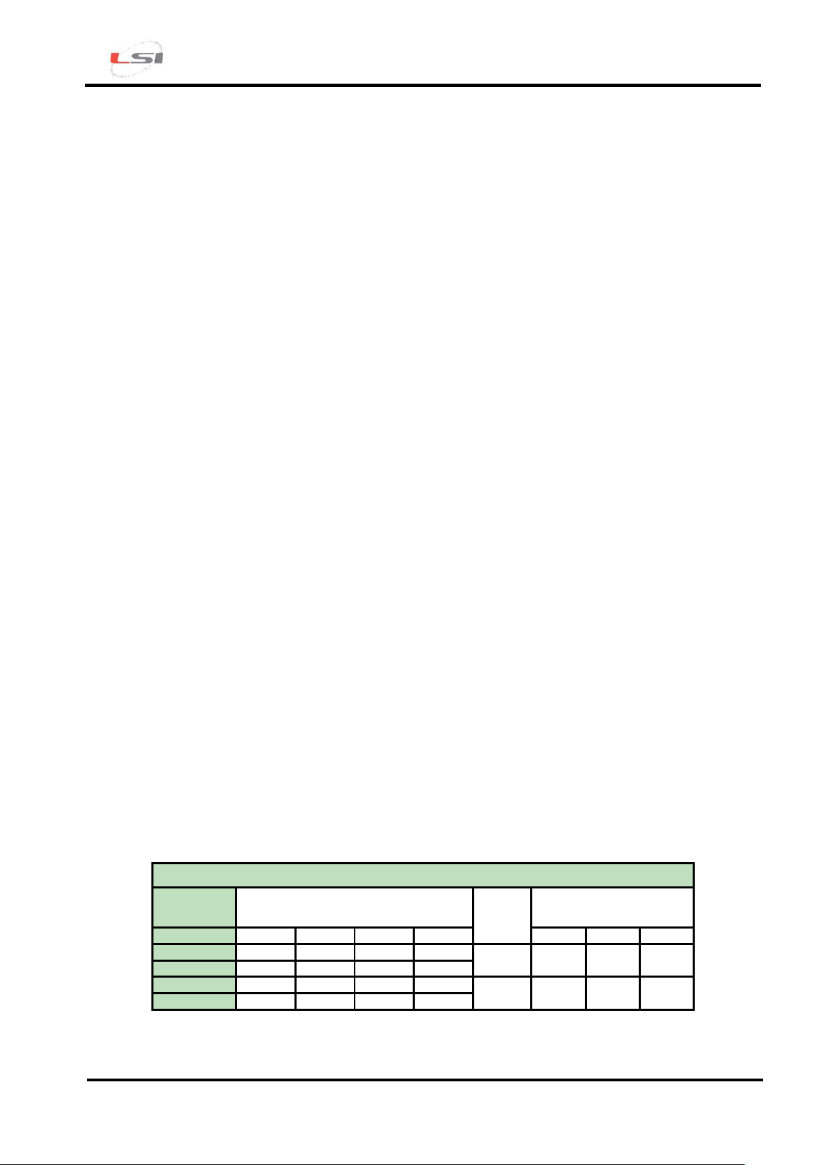
TERMINAL BOARD
Analogue
input
Signal
GND
Actuator
A B C D
Number
+V
0 V 1 1 2 3
4
7 1 5
6
2
17
18
19
20
3
8 9 10
11
23 2 21
22
4
24
25
26
27
3.3. Creating a configuration report
The Configuration Report contains all information concerning the configuration under consideration
including indications on how to connect the different probes to the instrument terminals:
Open the configuration under consideration;
Press the Report key on the Instrument bar;
Press OK on Measures Order;
Assign a name to the file by setting the save path.
If some measures have no connection assigned, a possible cause could be that the measure was
created without using the LSI LASTEM sensors registry.
It is recommended to print the document in order to be able to use it later when connecting the
probes to the datalogger.
3.4. Connecting the probes
It is recommended to connect the probes with the instrument turned off.
3.4.1. Electrical connection
For ELR516M and ELR515 models.
The probes should be connected to the datalogger inputs that were assigned with 3DOM. For this
reason, connect the probe to the terminal box as follows:
Identify the terminals to be used with the probe under consideration in the Configuration
Report;
Check for the congruence of the colors indicated in the Configuration Report with those
reported in the probe accompanying design; in case of discordances, refer to the probe
accompanying design.
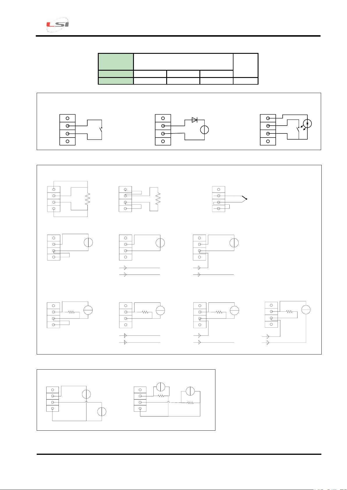
Failing information, refer to the tables and schemes below.
Page 15
R-Log – Quick Start
Cod. INSTUM_00953
Pag. 15
Digital
input
Signal
GND
E F
G
5
12
13
14
15 or 16
E
F
G
Digital status (on/off) Digital status of frequency signal
Frequency signal from optoelectronic
probe
E
F
G
E
F
G
+
+
A
B
C
D
A
B
C
D
A
B
C
D
A
B
C
D
A
B
C
D
4 wires resistance 2 wires resistance Thermocouple
Voltage signal from externally
powered sensor
Voltage signal from 4 wires
sensor powered (fixed or
switched) from E-Log
0 V
+12V (fixed or switched)
Probe power supply
-
+
A
B
C
D
Current signal from externally
powered probe
Rx
A
B
C
D
Current signal from 4 wires sensor
powered (fixed or switched) from
E-Log
0 V
+12V (fixed or switched)
Probe power supply
-
+
Rx
A
B
C
D
Rx
Current signal from 2 wires probe
(powered from signal wires)
+12V (fixed or switched)
0 V
+
+
+
+
+
+
A
B
C
D
Voltage signal from 3 wires
sensor powered (fixed or
switched) from E-Log
+12V (fixed or switched)
Probe power supply with 0V
as signal common
+
+
0 V
A
B
C
D
Current signal from 3 wires
sensor powered (fixed or
switched) from E-Log
0 V
+12V (fixed or switched)
+
Rx
+
Alimentazione sensore con 0V
comune a segnale
A
B
C
D
Voltage signal from externally
powered sensor
A
B
C
D
Current signal from externally
powered probe
Rx
+
+
+
a
b
Rx
+
a
b
Sensors with digital signal
Sensors with analog signal (differential mode)
Sensors with analog signal (single ended mode)
Page 16
R-Log – Quick Start
Cod. INSTUM_00953
Pag. 16
NOTE The voltage drop resistance indicated by Rx is used to report a voltage signal from the sensor-generated current.
3DOM program provides a list of settings for LSI LASTEM sensors, including some models with current output; for
these models, always use voltage drop resistances of 50 Ω to obtain voltage signals up to 1 V.
3.5. Displaying measures in fast acquisition mode
R-Log has a function that allows to acquire all sensors connected to its inputs (excluding the sensors
connected to the serial port) at maximum speed. In this way, it is possible to check for the
correctness of the operations performed until that moment. To activate the fast acquisition mode,
proceed as follows:
Turn the instrument on by simultaneously pressing and buttons;
Press simultaneously and buttons in the instant values display window;
Check, when possible, for the correctness and the consistency of the displayed values;
Press simultaneously and buttons to go back to normal mode.
A consistent amount of power is needed to display measurements in fast mode; if the instrument is
power supplied by a battery, it is advisable to go back to normal mode as soon as possible.
3.6. Starting the system and displaying
measurements
For a correct system startup, it is recommended to turn all instruments off and turn them on again
starting preferably from the Master following with Repeaters and Slave devices. Wait as long as
necessary for Repeaters and Slave devices to transmit measurements and for the Master to acquire
them.
Page 17
R-Log – Quick Start
Cod. INSTUM_00953
Pag. 17
4. Elaborated data storage options
To download data from the instrument memory with 3DOM, you need to configure data storage
modes, accessible in Options->Data Storage Configuration… or the Data Storage button in the
instrument bar or the instrument Data Storage...contextual menu. There are many possibilities;
indication will be given in this manual about how to set the two most commonly used storage modes,
that are:
Storage as an ASCII text file;
Storage on Gidas database (SQL).
4.1. Storing data in a text file
Select Check to activate data storage control box and set the desired storage modes (storage folder
path, file name, decimal separator, number of decimal digits…).
The created files are included in the selected folder and take a variable name based on the selected
settings:
[Basic folder]\[Serial number]\[Prefix]_[Serial number]_[yyyyMMdd_HHmmss].txt
Note
If the setting “Append data on the same file” is not selected, each time instrument data are
downloaded, a new data file is created.
The date used to indicate the storage file corresponds to the date of creation of the storage file and
NOT to the date/time of the first processed data available in the file.
4.2. Saving data on a Gidas database
Note
To store data on LSI LASTEM Gidas database for SQL Server 2005, you need to install the
GidasViewer program: it provides for the installation of the database and requests the activation
license for each instrument. Gidas database needs a SQL Server 2005 installed in the PC: if the
user hasn’t got this program installed, the free “Express” version can be downloaded. Refer to
GidasViewer program manual for additional details on GidasViewer installation.
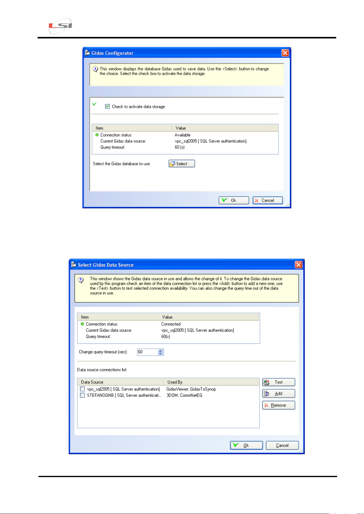
The configuration window for storage on Gidas database has the aspect below:
Page 18
R-Log – Quick Start
Cod. INSTUM_00953
Pag. 18
To enable storage, select Check to activate data storage control box.
The list shows the current connection status. This can be changed by pressing the Select key that
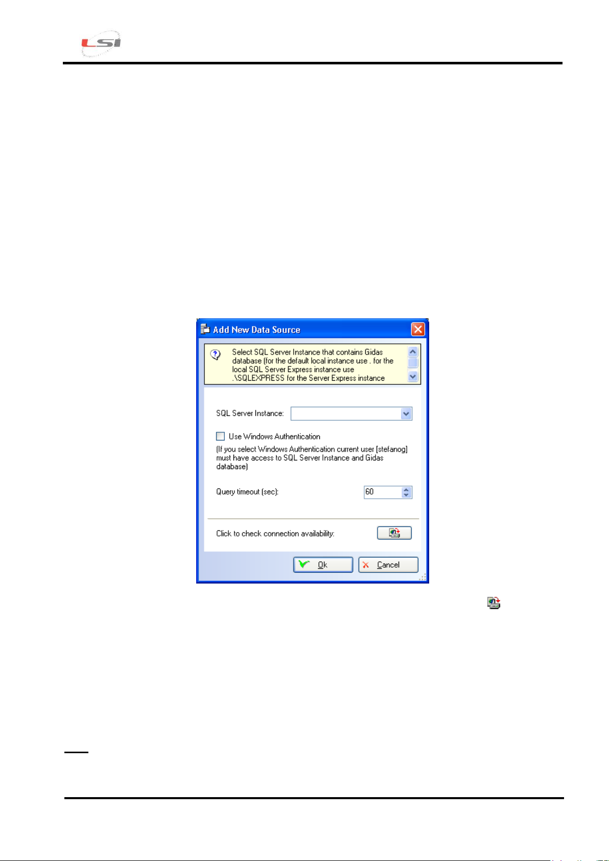
opens the configuration window for connection to Gidas database:
Page 19
R-Log – Quick Start
Cod. INSTUM_00953
Pag. 19
This window displays the Gidas data source in use and allows its change. To change the data source
used by the program, select an item from the list of the available data sources or add a new one by
pressing Add; use the Test key to check for the availability of the selected data source.
The list of the available data sources includes the list of all data sources entered by the user, it is
therefore initially blank. The list shows also the data source used by the different LSI-Lastem
programs making use of Gidas database. Obviously, only the information concerning the installed
and configured programs is displayed.
The Remove key eliminates a data source from the list; this operation does NOT change the
configuration of the programs that use the removed data source and that will continue to use it.
The timeout for data requests from the database can also be changed.
To add a new connection, select the Add key of the previous window, that opens the Add window for
a new data source.
Specify the SQL Server 2005 instance where to connect and check connection with button. The
list only shows the instances in the local computer. SQL Server instances are identified as follows:
where servername represents the network name of the computer where SQL Server is installed; for
local instances, either the computer name, the name (local) or the simple dot character can be used.
In this window, the timeout for the database data request can be set as well.
Note
Use Windows authentication only in the event the connection check fails. If you connect to a
network instance and Windows authentication fails, contact your database administrator.
servername\instance name
Page 20
R-Log – Quick Start
Cod. INSTUM_00953
Pag. 20
5. Receiving elaborated data
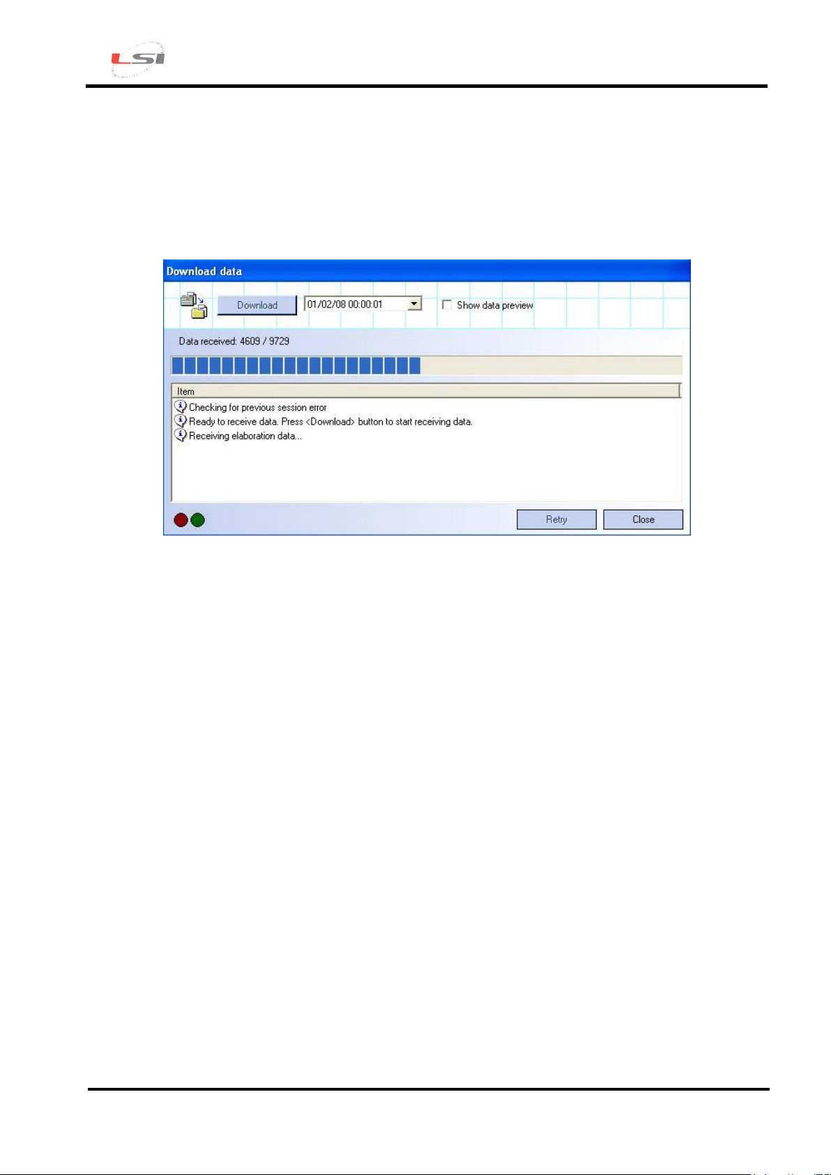
To receive the elaborated data from 3DOM, select the Communication-> Elaborated Data… menu
or press the Elab. Values button on the instrument bar of Instrument or the Elaborated Data…
contextual menu of the instrument.
If the program succeeds in establishing a communication with the selected instrument, the Download
button is enabled; proceed then as follows:
Select the date from which to start downloading data; in case some data were already been
downloaded, the control proposes the date of the last download;
Select the Show data preview box if you want to display data before saving them;
Press the Download button to download data and save them in the selected archive files.
6. Displaying elaborated data
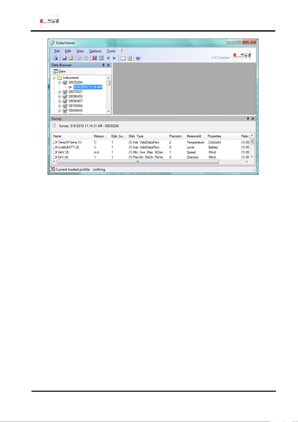
The elaborated data filed in Gidas database can be displayed with Gidas Viewer software. At startup,
the program has the following aspect:
Page 21
R-Log – Quick Start
Cod. INSTUM_00953
Pag. 21
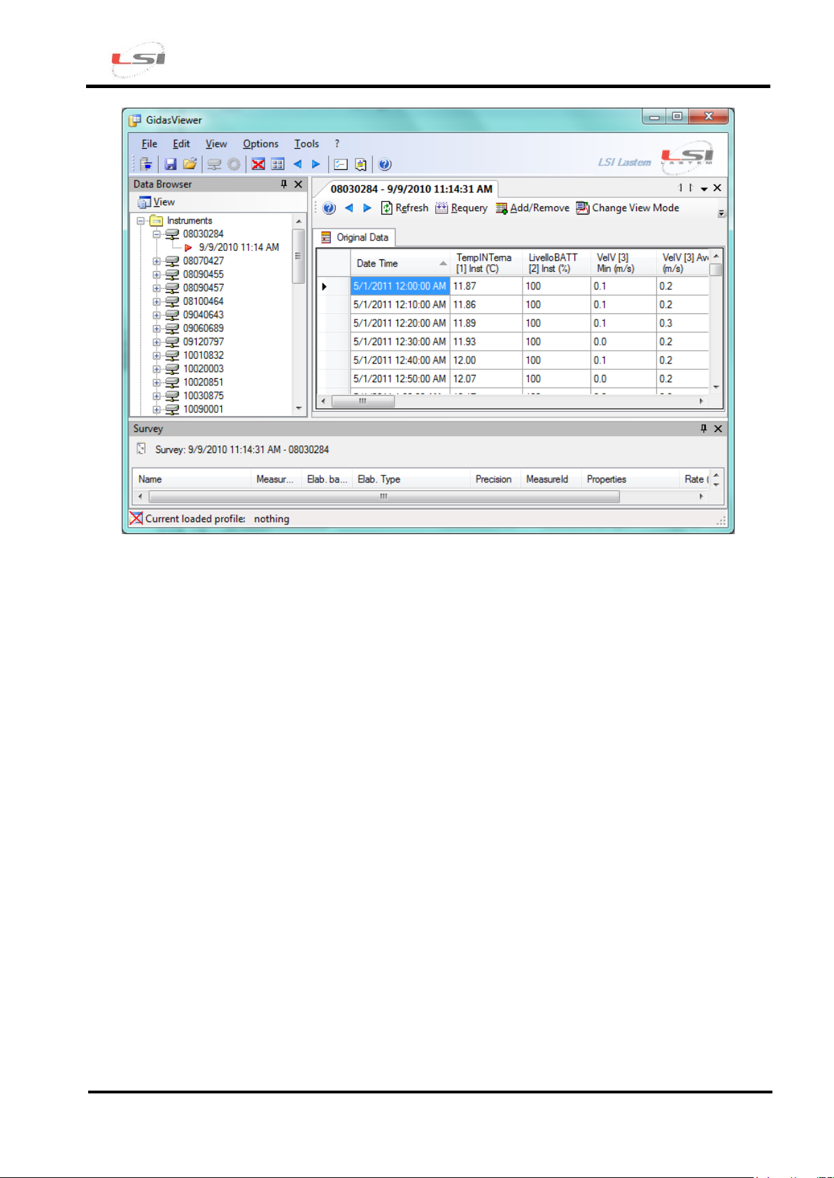
To display data, proceed as follows:
Expand the branch corresponding to the instrument serial number that appears in the Data
Browser;
Select the identified acquisition with the starting date/time of measurements;
Press the selected acquisition with the right key of your mouse and choose Show Data (for
the wind direction measurement, select Show Wind Rose Data or Show Weibull Wind Rose
Distribution);
Set the elements for data research and press OK; the program will display data in table format
as shown below;
Page 22
R-Log – Quick Start
Cod. INSTUM_00953
Pag. 22
To display the chart select Show Chart on the table with the right key of your mouse.
Enjoy your R-Log
 Loading...