

Page 1
SAFETY PRECAUTIONS
WARNING
CAUTION
CAUTION
Thank you for using our S100 Profibus-DP Communication module
Safety PRECAUTIONS
Always follow safety instructions to prevent accidents and potential hazards
from occurring .
Safety precautions are classified into “WARNING” and “CAUTION” and their
meanings are as f ollows:
The indicated illustrations on the product and in the manual have the
following mea nings.
Danger may be present. Read the message and follow the instructions
Improper operation may result in serious personal injury
or death.
Improper operation may result in slight to medium
personal injury or property damage
carefully.
Particular attention should be paid because danger of an e lec tric shock
may be present.
Keep operating instructions handy for quick reference.
Read the operating instruc tions carefully to fully understand the functi o ns of
the S100 seri es an d to use it properly.
Be cautious, when handling the CMOS components of the
communication modul e.
Static may lead to malfunctioning of the product.
Turn off the inverter p o wer, when changing the communication cable.
Otherwise, you may damage the module or a communication error may occur.
Make sure to insert the Communication module connector to the
inverter precisely.
Otherwise, you may damage the module or a communi cati on erro r may occur.
Check the parameter unit before setting up the parameter.
Otherwise, a communication error may occur.
i
Page 2

Table of Contents
1.2 Components
2.6 Maximum Distance according to the Baud rate
3.2 LED information & Troubleshooting
................................................................................. 10
4.2 Description of Profibus-DP Communication Parameters
............................................... 14
Table of Contents
Chapter 1. Introduction .............................................................................................. 1
1.1 What is Profibus-DP Communication Module?
...................................................................................................................... 1
Chapter 2. Profibus-DP Communication Module ........................................................... 2
2.1 Technical Specification of Profibus-DP Communication
2.2 Layout of Profibus-DP Communication Module
2.3 General Specification of Profibus-DP Connector
2.4 Installation
2.5 Network Cable Specifications
............................................................................................................................. 5
............................................................................................. 7
Chapter 3. Status Diagnosis and LED Indication ............................................................ 9
3.1 LED display feature
.............................................................................................................. 9
............................................................. 1
................................................. 2
................................................................ 3
.............................................................. 4
................................................................. 8
Chapter 4. Inverter Parameter ................................................................................... 13
4.1 Profibus-DP Communication Parameter List
4.2.1 Version of Communication module ................................................................................................................. 14
4.2.2 Station ID setting ..................................................................................................................................................... 14
4.2.3 LED indication for communication status ..................................................................................................... 15
4.2.4 The number of Para Status setting .................................................................................................................. 16
4.2.5 Para Status 1~8 ......................................................................................................................................................... 17
4.2.6 Number of Para Control setting ........................................................................................................................ 18
4.2.7 Para Control 1~8 ...................................................................................................................................................... 19
4.2.8 Comm Update ........................................................................................................................................................... 20
................................................................... 13
Chapter 5. GSD File (Electronic Data Sheets).............................................................. 21
ii
Page 3

Chapter1. Introduction
Chapter 1. Introduction
This Profibus-DP communication module allows the LSLV-S100
inverter to be connected to Profibus network.
This module does not su pport IP66 products.
1.1
What is Profibus-DP Communication Module?
A controlling and monitoring of inverter can be controlled by PLC
sequence progra m or a Profibus Master Module.
It helps the installation cost reduced since multiple inverters are
implemented by a communication line. In addition, the wiring is so
simple that the installation time will be reduced and the maintenance
will be improved.
Factory automation can be also easily operated by Mixed-used
development of auxiliary devices of PLC and other control systems
such as PC for controlli ng t h e inverter.
1.2
Components
This product is consi sting of these kinds of parts
- Profibus-DP Communication Module(CPDP-S100): 1 ea
- Profibus-DP Communication Module Manual: 1 ea
- Brass Bar(M3xL23): 1 ea
- Brass Bar(M3xL17.3): 1 ea
- Fixed Screw(M3xL8): 1 ea
- Profibus connect or: 1 ea
1
Page 4
Chapter2. Profibus-DP Communication Module
Auto Baud rate
Detect
Synchronization
Mode
Max. Output
Length
9.6K, 19.2K, 93.75K, 187.5K, 500K, 1.5M, 3M,
6M, 12M
Max. Connectable
Number of Nodes
Max. 32 nodes without repeater
(including mast er m odu le)
Communication
Connector
Chapter 2. Profibus-DP Communication Module
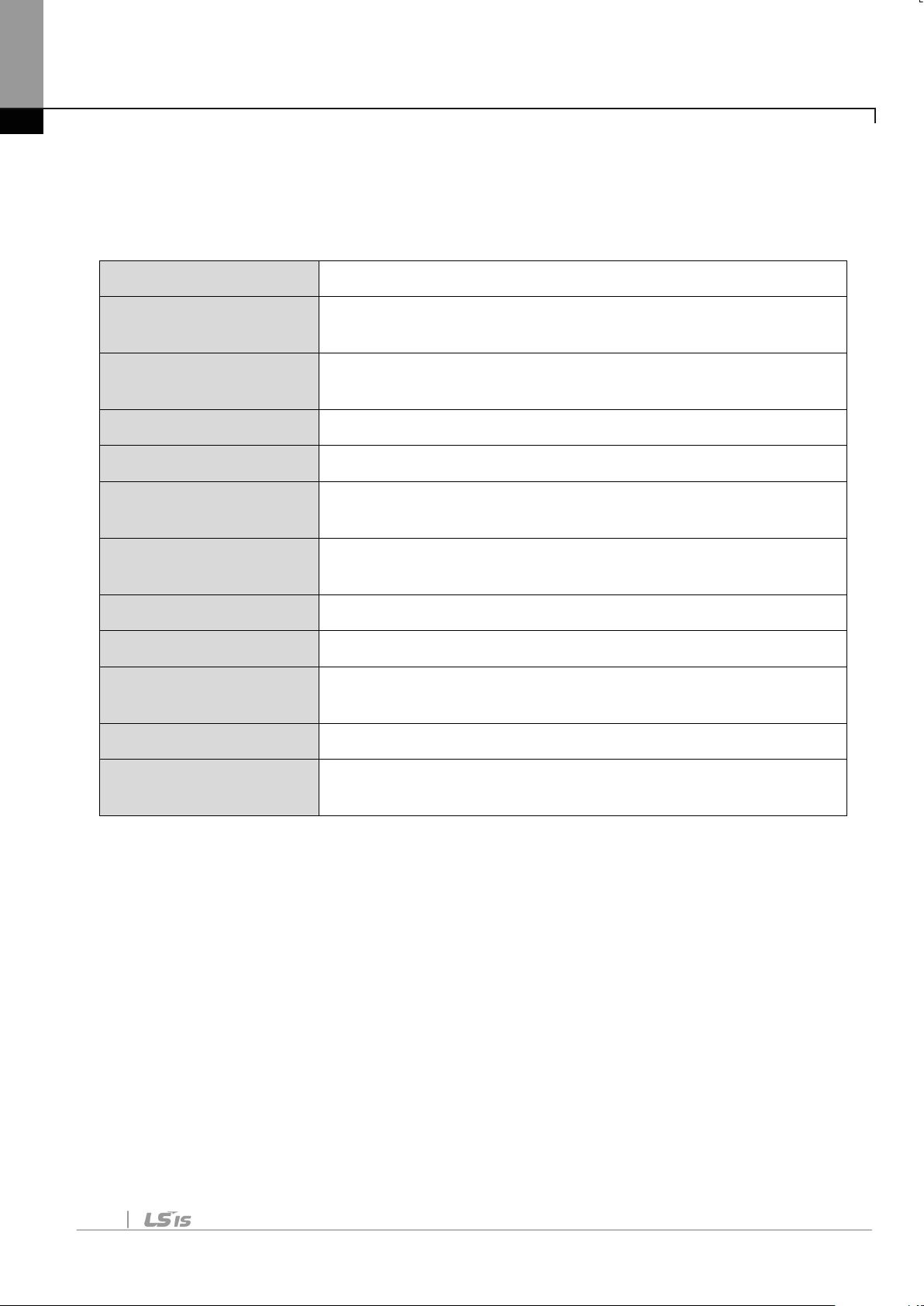
2.1 Technical Specification of Profibus-DP Communication
Device Type Profibus DP Slave
Supported
Supported
Freeze Mode Supported
Max. Input Length 8 words
8 words
Baud rate Support
Modular Station Supported
Max. Module 2
LED 3 LEDs (ONLINE, ERR, and CPU)
9Pin D-sub
Table 1 Technical Data
2
Page 5
Chapter2. Profibus-DP Communication Module
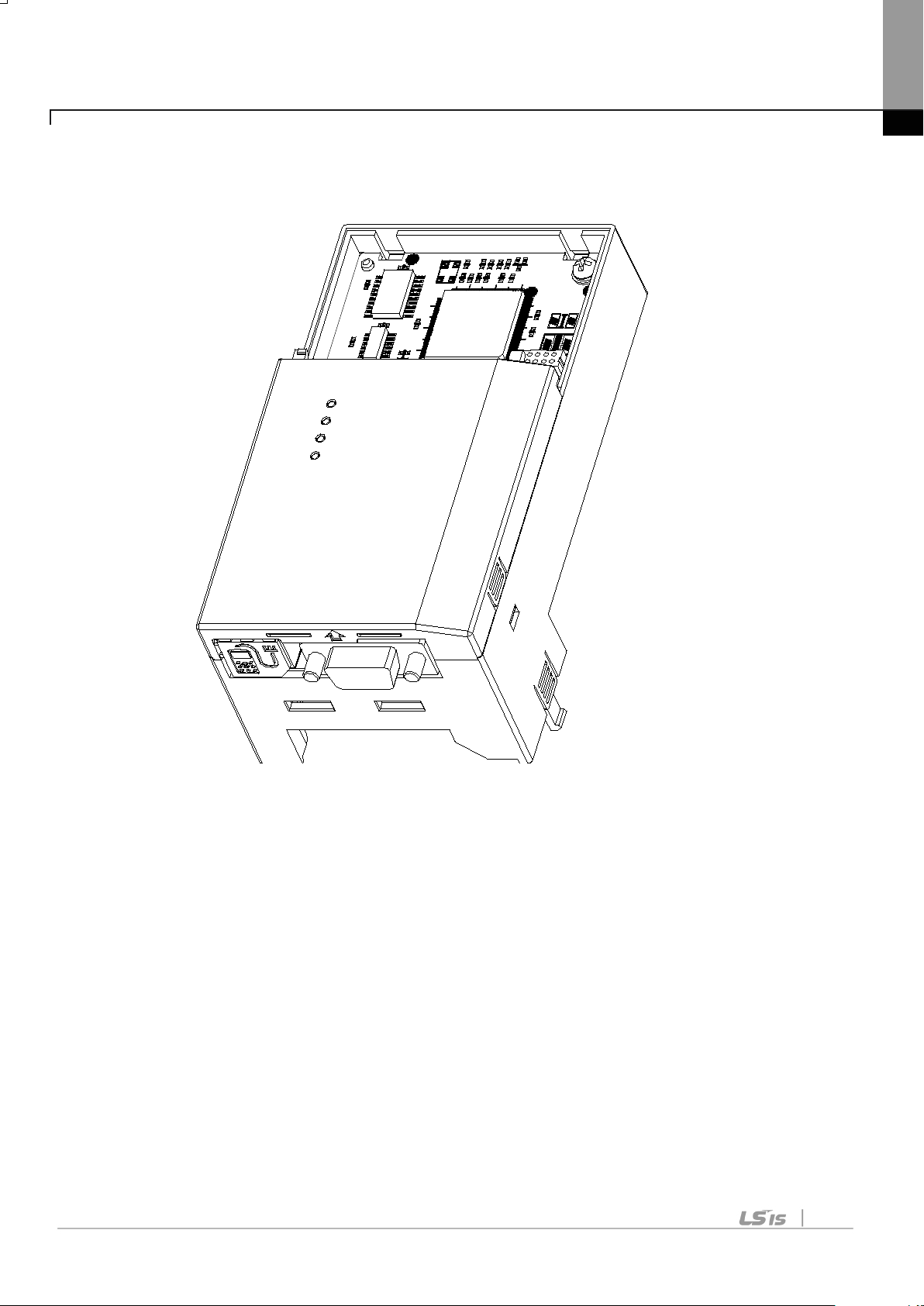
2.2 Layout of Profi bus-DP Communicati on M odule
Figure 1 Profibus-DP Communication Module
3
Page 6
Chapter2. Profibus-DP Communication Module
Connector
1
None
None
2
M24
24V output GND
Transmitter/Receiver data
Plus
4
CTRL-P
Control signal for a repeater
5
DGND
Signal GND
6
VP
5V for terminati ng resistance
7
P24
24V output Plus
Negative
9
CTRL-N
Control signal for a repeater
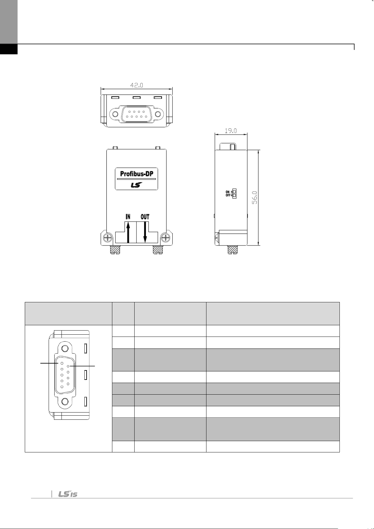
2.3 General Specification of Profibus-DP Connector
PROFIBUS
1
Figure 2 Profibus Connector
Pin Signal Description
3 RxD/TxD-P
6
Transmitter/Receiver data
8 RxD/TxD-N
note) The product only provides No.3, 5, 6 and 8 signals.
4
Table 2 Signal Description
Page 7
Chapter2. Profibus-DP Communication Module
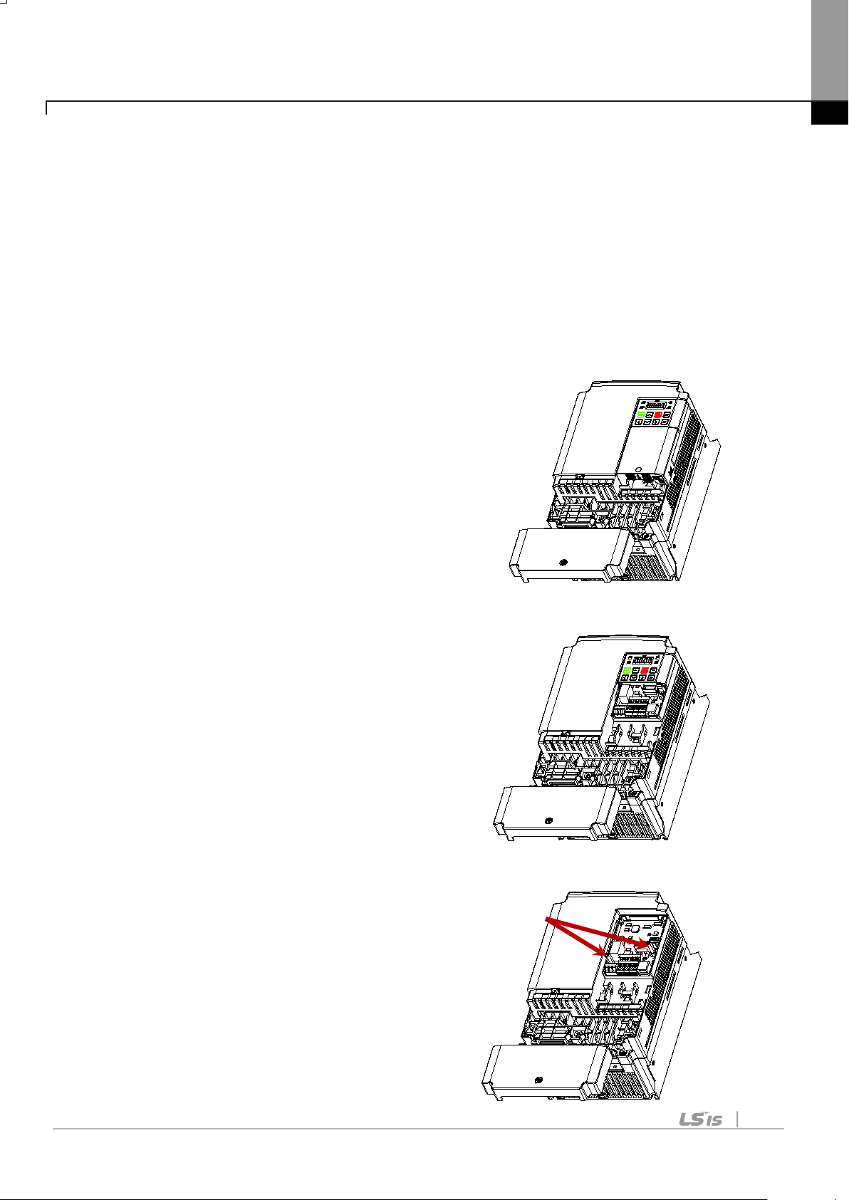
2.4 Installatio n
Warning) Connect a communication network after the power supply
is off. If Profibus-DP communication module is removed or
installed, the power supply should be switched off. Otherwise, the
S100 inverter wi ll be dam age d entirely.
Tak e off Profibus-DP communication module from the product after
the power supply is totally discharged.
■ Unfasten the front cover fixing bolt
to remove the front cover and
remove I/O cover((1), (2)) from
a dedicated inverter
for communication.
■ Remove the keypad (3).
(2)
(1)
(3)
■ Unfasten a screw from
I/O board and
(4)
fasten the prep a red
brass bar(4).
5
Page 8
Chapter2. Profibus-DP Communication Module
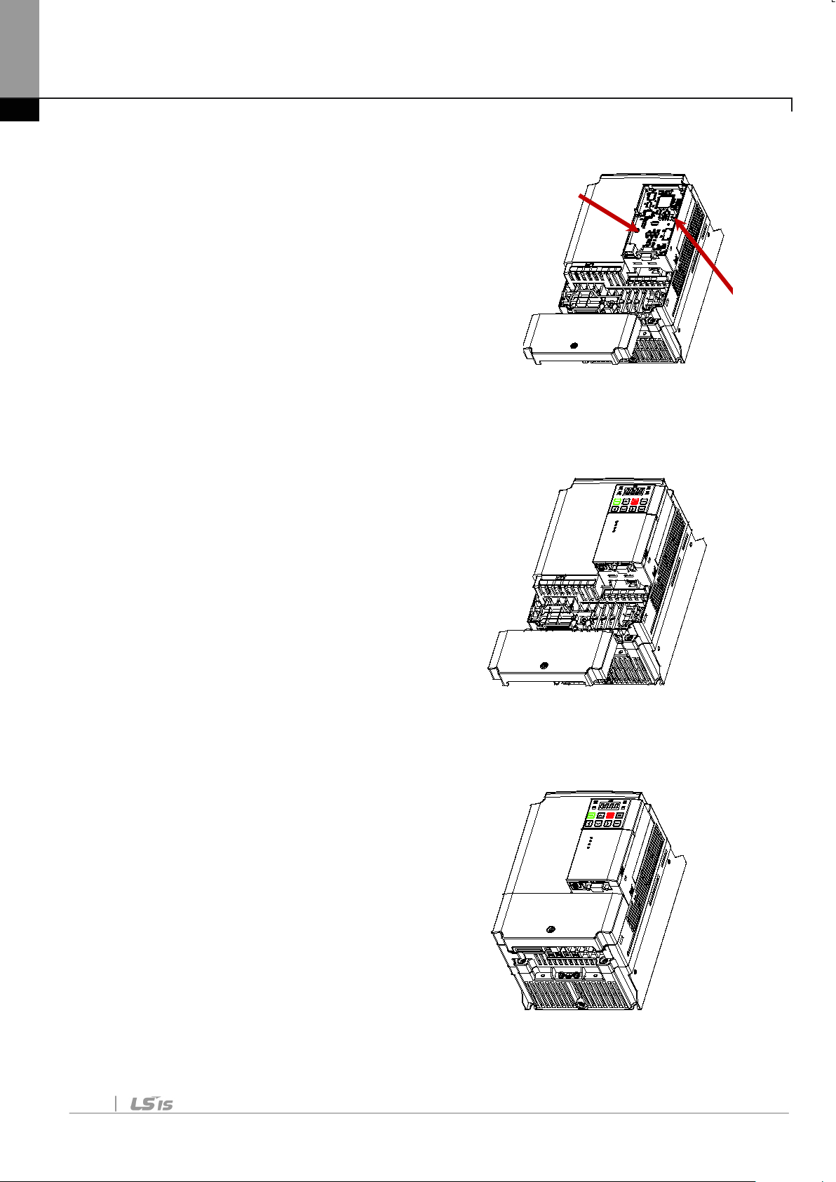
■ Mount Profibus-DP communication Module
and fasten the removed screw(6)
and the included screw(7).
■ Install the keypad (8) at first and
the communicatio n mo dule
cover(9) in order.
(5) (6)
(7)
(8)
(9)
■ Install the front cover(10) again
And installation is completed.
(10)
6
Page 9
Chapter2. Profibus-DP Communication Module
AWG
22
Material
Insulation
Material
Insulation
Tension
Inner Shield
Material
Aluminum Foil-Polyester,
Tape/Braid Shield
Electrostatic
Capacity
Specific
Impedance
of Conductors
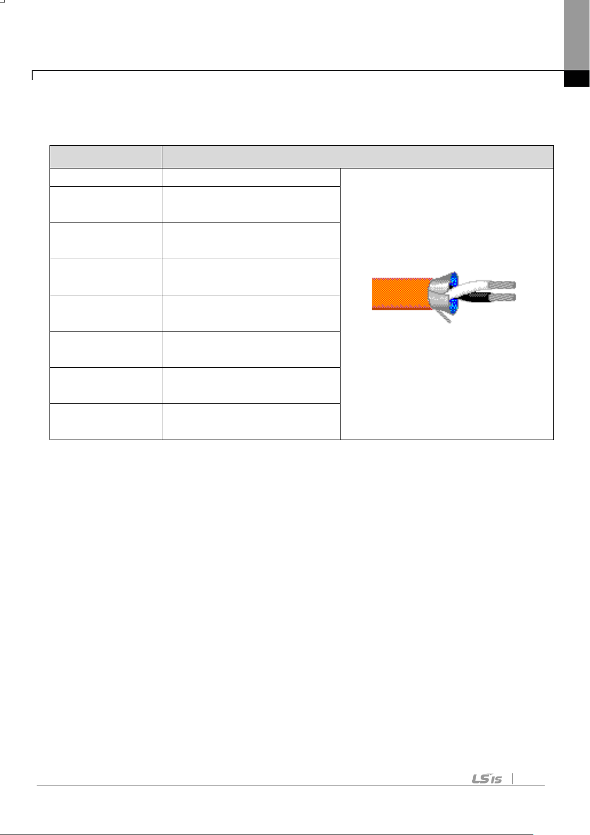
2.5 Network Cable Specifications
Classification
Conductor
Total number
Description
BC-Bare Copper
PE-Polyethylene
0.035 inch
8500pF/ft
150Ω
2 Core
Table 3 Network Cable Specifications
7
Page 10
Chapter2. Profibus-DP Communication Module
Max. Extension
Distance
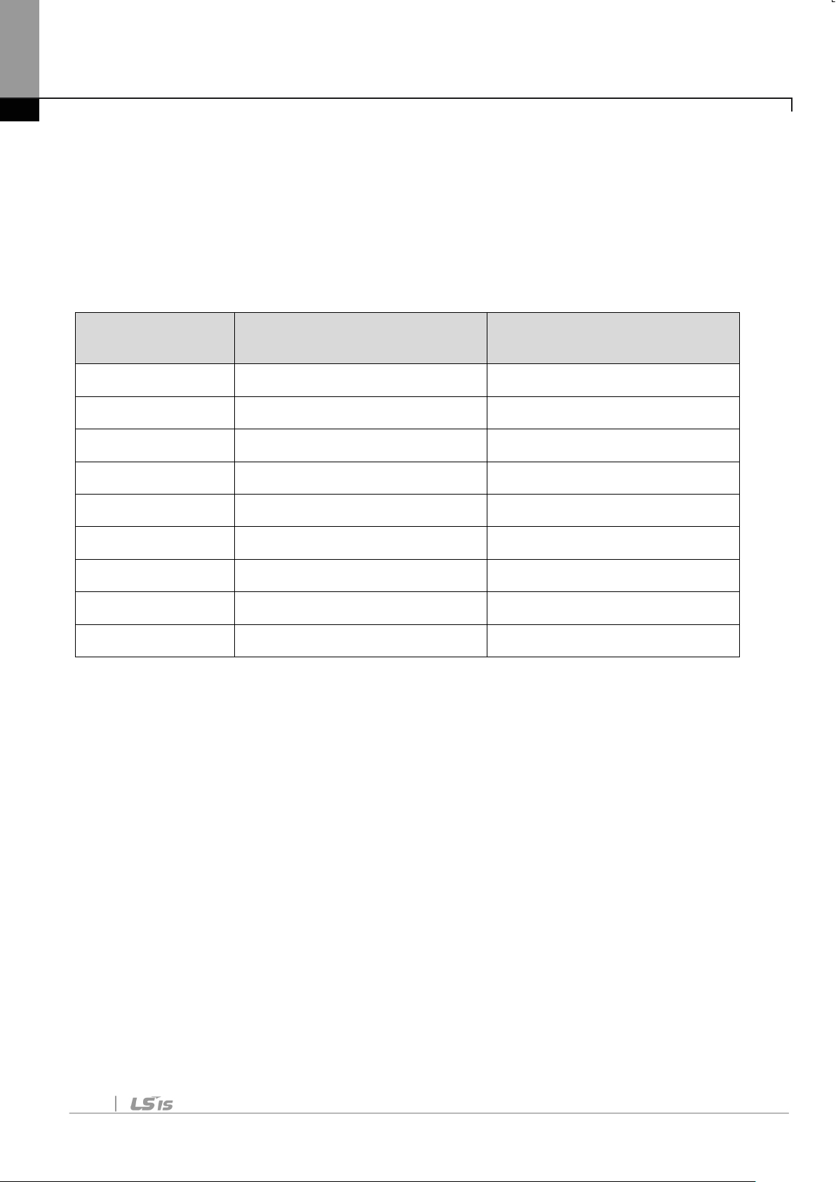
2.6 Maximum Distance according to the B aud rate
The total BUS length of a network configuration is differed
according to the baud rate. The communication quality is not
guaranteed when the total distance exceeds the total BUS length
limit as below.
Baud rate Max. Segment Length
12 Mbps
6 Mbps
1,000 m / 3,278 feet 10,000 m / 32,786 feet
1,000 m / 3,278 feet 10,000 m / 32,786 feet
3 Mbps 1,000 m / 3,278 feet 10,000 m / 32,786 feet
1.5 Mbps
500 kbps
1,000 m / 3,278 feet 10,000 m / 32,786 feet
400 m / 1,311 feet 4,000 m / 13,114 feet
187.5 kbps 200 m / 655 feet 2,000 m / 6,557 feet
93.75 kbps
19.2 kbps
100 m / 327 feet 1,000 m / 3,278 feet
100 m / 327 feet 1,000 m / 3,278 feet
9.6 kbps 100 m / 327 feet 1,000 m / 3,278 feet
Table 4 Maximum Distance according to the Baudrate
8
Page 11
Chapter3. Status Diagnostic and LED Indication
when the communication module
power is
generated.
Chapter 3. Status Diagnosis and LED Indication
3.1 LED display feature
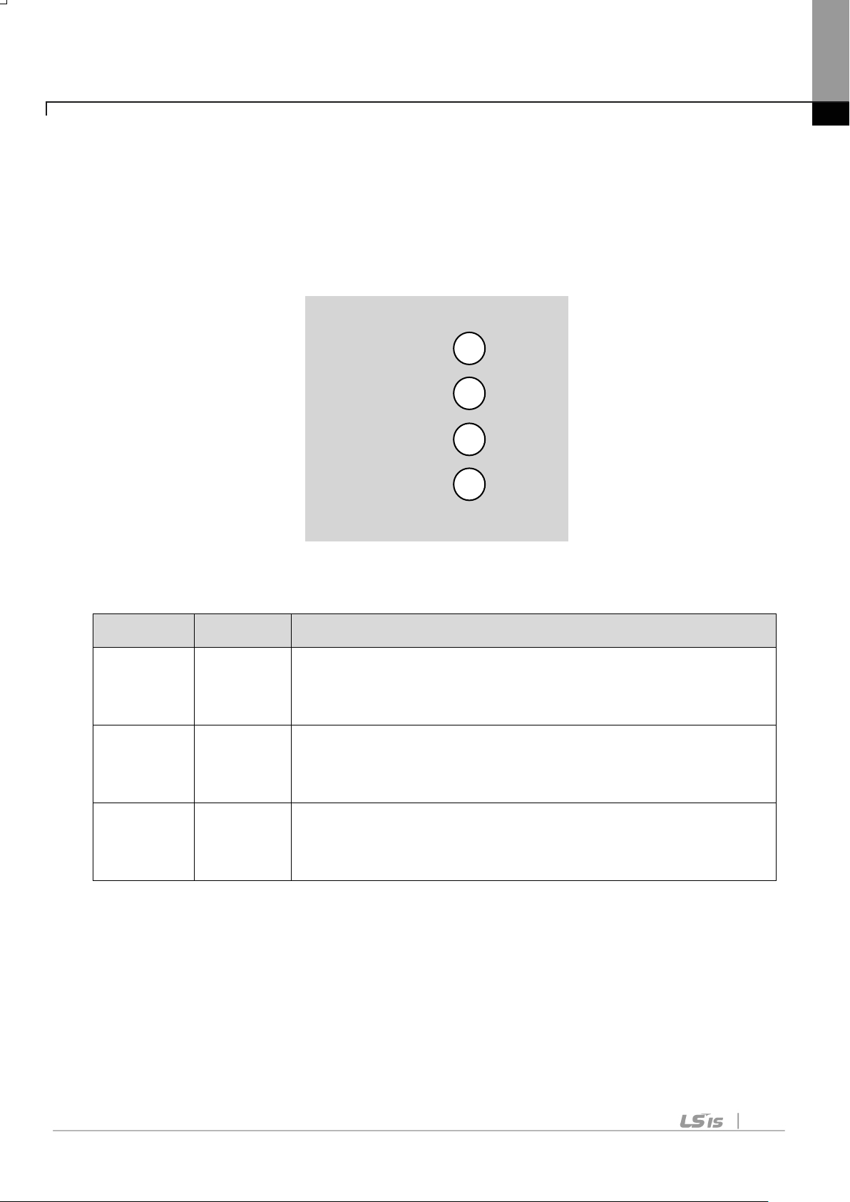
The profibus DP Module ha s 3 kinds of LEDs, referring to the below
table colored by LEDs for troubleshooting and diagnostic s.
CPU
ERROR
ONLINE
Figure 3 LED display
LED Color Description
LED turns “On”
CPU Green
is installed on the inverter and the
ERR Red
LED turns “On” if there is something wrong in the
Profibus-DP communication module.
LED always turns “On” when Profibus-DP
ONLINE Green
communication modu l e is on-line status.
Table 5 LED Indication
9
Page 12
Chapter3. Status Diagnostic and LED Indication
Check power
of inverter.
second
operation
Normal
operation
of inverter.
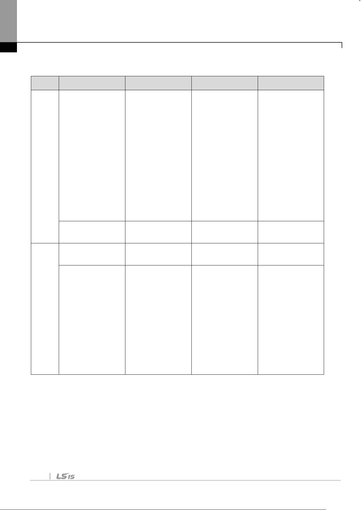
3.2 LED information & Troubleshooting
LED
CPU
LED Status Module Status Cause
Power supply
unplugged or
contact failure
Failure in
OFF
between the
power supply
inverter and
Profibus-DP
module.
Blinking every
Normal
Normal
OFF Normal
Troubleshooting
supply.
Check the
inverter’s
malfunction.
Check the
connection
between
Profibus-DP
module and
the connector
-
-
ERR
Blinking every
second
(with CPU
LED together)
The
communication
is interrupted.
The
communication
is not available
between the
inverter and
the
communication
module.
Check
inverter’s
malfunction.
Check the
connection
between
Profibus-DP
module and
the connector
10
Page 13
Chapter3. Status Diagnostic and LED Indication
Check if the
communicatio
Blinking every
second
(contrary to
CPU LED)
CONFIG
ERROR
Master’s
configuration
Data is
different from
Profibus-DP
module’s
configuration.
Master doesn’t
work for
communication
in the network.
Check the
configuration
data set on
Master and
the internal
configuration
data at the
inverter.
Start the
communication
from Master.
Check the
ON-
LINE
OFF Off-Line
The
connection of
connector has
a problem.
There is no
master in the
network.
Wrong setting
connection
between the
pin number of
connector and
the termination
resistor.
It can be
possible there
is no
designated
master or
master has a
problem.
station ID set
in the
11
of station ID
designated
Profibus
Page 14
Chapter3. Status Diagnostic and LED Indication
n module is
network.
repeater.
Network,
the same as
the station ID
set from the
keypad of
inverter in
Configuration
tool and
station ID is
unique in the
Check if it
exceeds the
length limit of
ON On-Line
Network
Configuration
Fault
Station,
Parameterization
and
segment.
Check if the
connections
with Segment
are over 32
stations
including a
repeater.
Check if the
connections
with network
are over 126
stations
including
-
12
Configuration
are normal
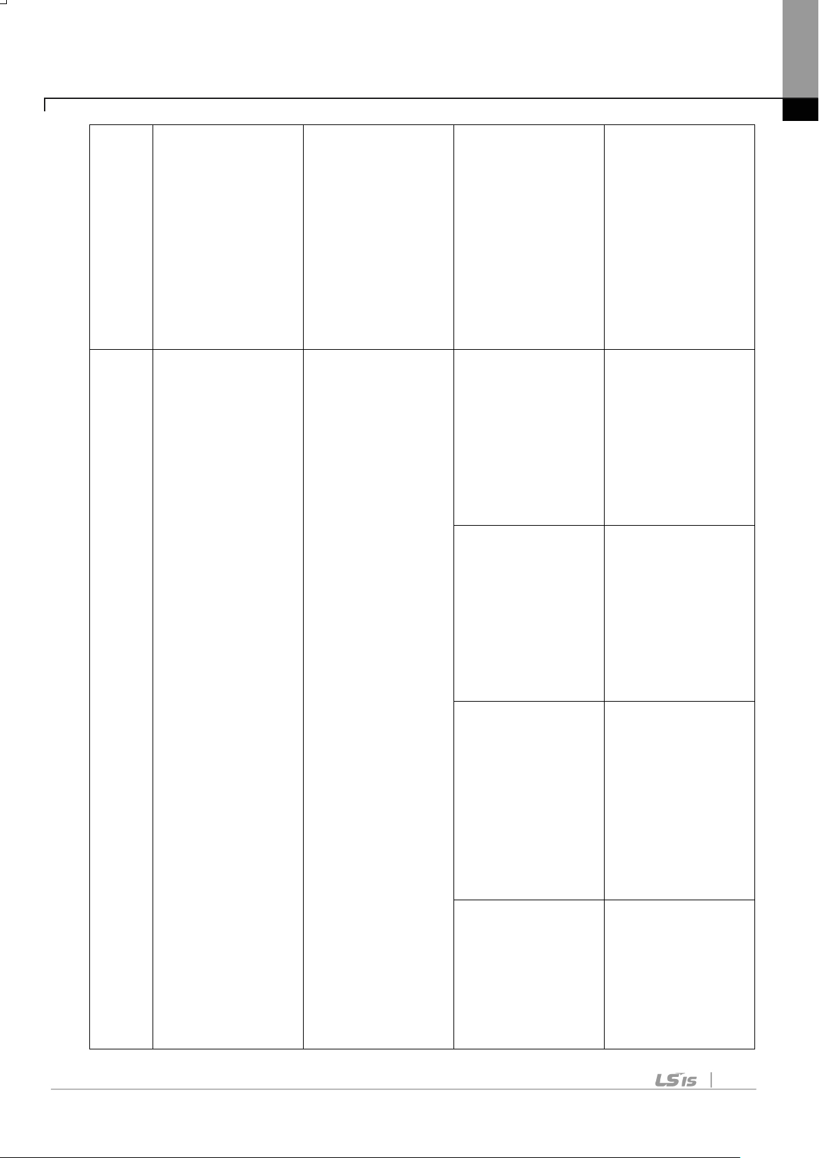
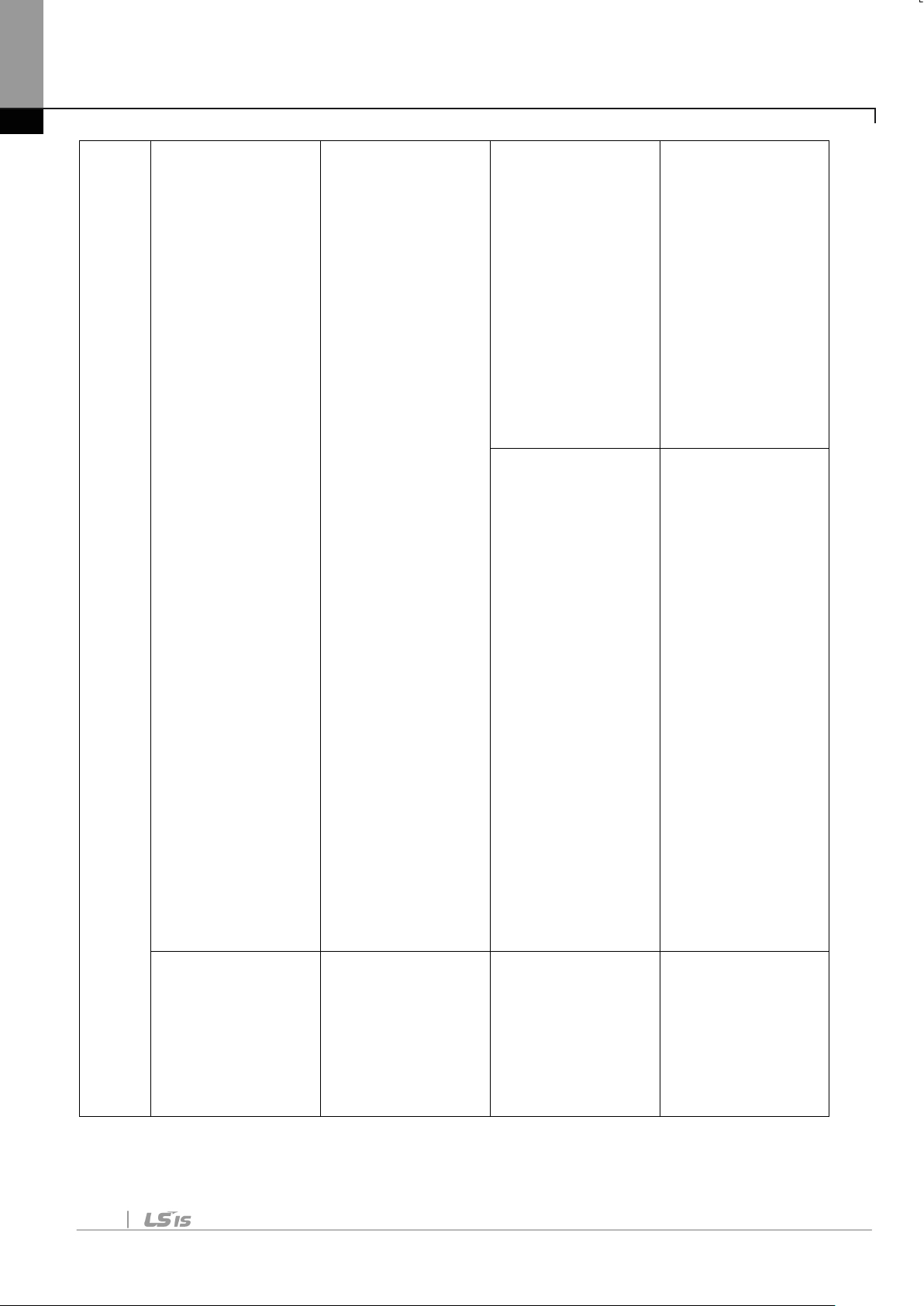
Table 6 Diagnostics according to LED Status
Page 15
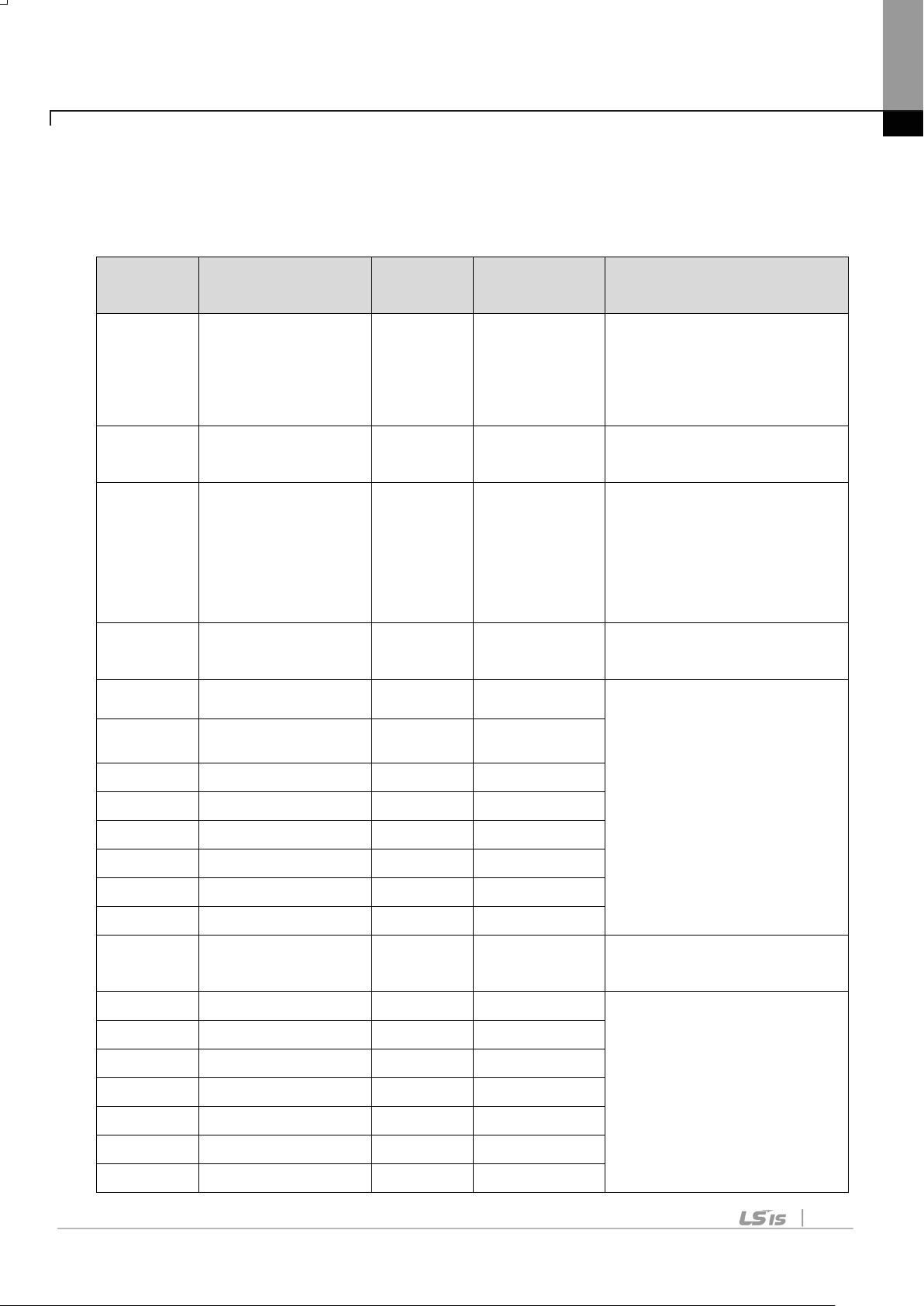
Chapter4. Inverter Parameter
Indicate the version
module.
Set up the station of
Profibus-DP module.
Show the ON/OFF
module.
ParaStatus
Num
Set up the Status
number for use.
CM-33
Para Status-3
0x000F
0~0xFFFF
CM-34
Para Status-4
0x0000
0~0xFFFF
CM-35
Para Status-5
0x0000
0~0xFFFF
CM-36
Para Status-6
0x0000
0~0xFFFF
CM-37
Para Status-7
0x0000
0~0xFFFF
CM-38
Para Status-8
0x0000
0~0xFFFF
Set up Control
number for use.
CM-51
Para Control-1
0x0005
0~0xFFFF
Chapter 4. Inverter Parameter
4.1 Profibus-DP Communication Parameter List
Code
Number
The name of
Parameter
Initial
Range Definition
Value
CM-06 FBus S/W Ver - -
CM-07 FBus ID 1 1 ~ 125
CM-09 FBus Led - -
CM-30
3 0~8
CM-31 Para Status-1 0x000A 0~0xFFFF
of Profibus-DP
communication
data of the LED on
Profibus-DP
communication
CM-32 Para Status-2 0x000E 0~0xFFFF
CM-50 Para Ctrl Num 2 0~8
CM-52 Para Control-2 0x0006 0~0xFFFF
CM-53 Para Control-3 0x0000 0~0xFFFF
CM-54 Para Control-4 0x0000 0~0xFFFF
CM-55 Para Control-5 0x0000 0~0xFFFF
CM-56 Para Control-6 0x0000 0~0xFFFF
CM-57 Para Control-7 0x0000 0~0xFFFF
Set up Status
address which will be
read by Master.
Set up control
address controlled by
Profibus DP Master.
13
Page 16
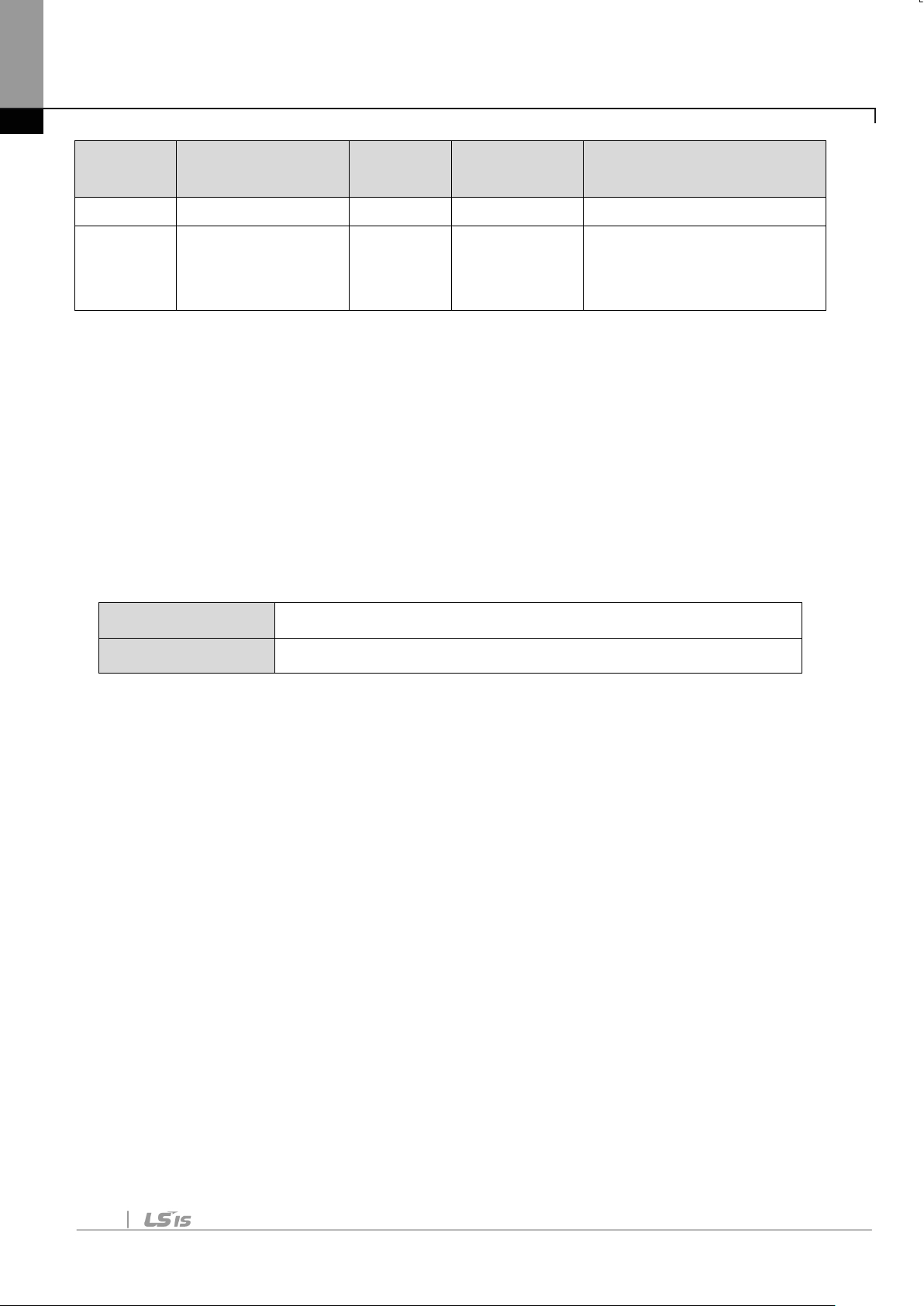
Chapter4. Inverter Parameter
CM-58
Para Control-8
0x0000
0~0xFFFF
Update keypad
communication.
Code
The name of
Initial
Range Definition
Number
Parameter
Value
0:NO
CM-94 Comm Update 0
parameters relating to
1:YES
Table 7 Inverter Parameters
4.2 Description of Profibus-DP Communication Parameters
4.2.1 Version of Communication module
It displays the version of Profibus-DP module installed on the inverter.
4.2.2 Station ID setting
CM-07 FBus ID
CM-94 Comm Update
The parameter sets the value of Station ID at Profibus-DP module.
Station ID can be set up within the range of 1~125 and it cannot be
duplicated to write. It nee ds to check if the settled Station ID is not
equal to other Station ID in network.
If the value of Station ID is changed, set ‘CM-94(Comm Update)’ to
‘1’ to apply the changed value of Station ID to Profibus-DP
Communication module.
14
Page 17
Chapter4. Inverter Parameter
ON-LINE
(GREEN)
ERR
(RED)
CPU
(GREEN)
(ON)
(OFF)
Reserved ON-LINE ERR CPU
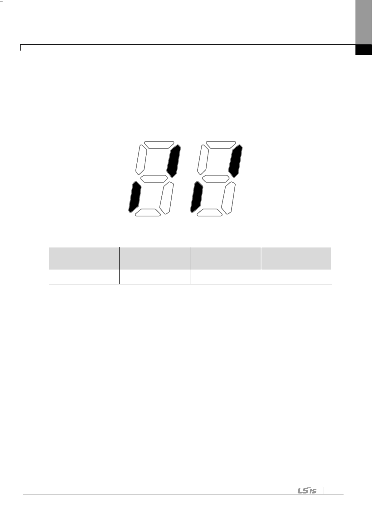
4.2.3 LED indication for communication status
Profibus-DP communication module has 3 LEDs, ONLINE, ERR,
and CPU on the keypad in order from left to right. It indicates
communication status by LED’s On/Off.
(CM-05 Status Example)
Reserved
OFF ON OFF ON
15
Page 18
Chapter4. Inverter Parameter
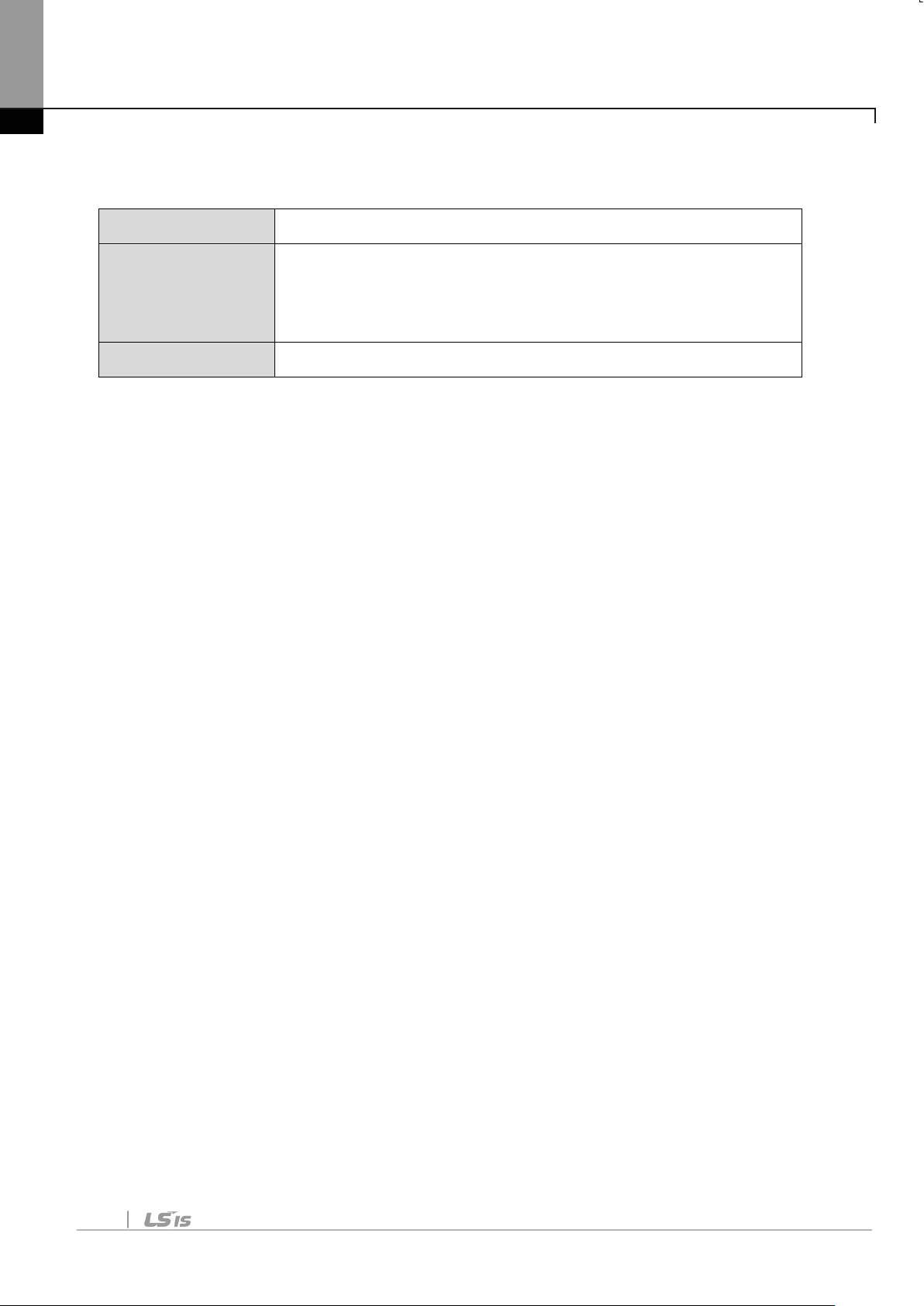
4.2.4 The number of Para Status setting
CM-30 The number of Para Status setting
CM-31
~
Para Status1~Status8 setting
CM-38
CM-94 Comm Update
This parameter determines how much status information will be
sent to Master by an inverter through Profibus-DP communication.
It can be set from 0 to 8. Para Status has to be set as the number of
Para Status (From CM-31 to CM-38 as preset number).
For example, If CM-30 is set to ‘3’, Para Status should be set from
CM-31 to CM-33. If CM-30 is set to ‘6’, Para Status should be set
from CM-31 to CM-36.
If the number of Para status is changed, set ‘CM-94(Comm Update)’
to ‘1’ to apply the changed number of Para Status to Profibus-DP
Communication module.
16
Page 19
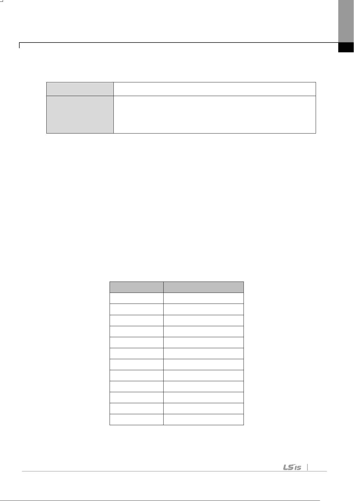
Chapter4. Inverter Parameter
Group
Group Number
1
2
Ad Group
3
4
5
6
7
8
9
10
11
12
4.2.5 Para Status 1~8
CM-30 Number of Para Status setting
CM-31
Para Status1~Status8 setting
~
CM-38
It determines that what status information will be sent to Master
through Profibus-DP communication.
Para Status 1~8 are set in the form of inverter address. They set up
the address for the common inverter area and the inverter keypad
parameter. If the keypad parameter address is written, it will be
saved in the form of 0x1000 + (‘Group number’ x 0x100) + (‘Code
number’).
For example, if DI Status of No. 90 at n Group are set to Para
Status-1, it should be set to 0x155A.
0x1000 + 0x05 x 0x100 + 0x5A(Dec 90) = 0x155A
dr Group
bA Group
Cn Group
In Group
OU Group
CM Group
AP Group
(Reserved)
(Reserved)
PRT Group
M2 Group
17
Page 20

Chapter4. Inverter Parameter
4.2.6 Number of Para Control setting
CM-50 Number of Para Control setting
CM-51
~
Para Control 1 ~ Contr ol 8 setting
CM-58
CM-94 Comm Update
It determines that how much control information will be sent to
inverter by Master through Profibus-DP communication.
It can be set up within the range of 0 to 8. Para Control has to be
set as the number of Para Control. (From CM-51 to CM-58 as
preset number)
For example, If CM-50 is set to ‘2’, Para Control should be set from
CM-51 to CM-52. If CM-50 is set to ‘5’, Para Control should be set
from CM-51 to CM-55.
If the number of Para status is changed, set ‘CM-99(Comm Update)’
to ‘1’ to apply the changed number of Para Control to Profibus-DP
communication module.
18
Page 21
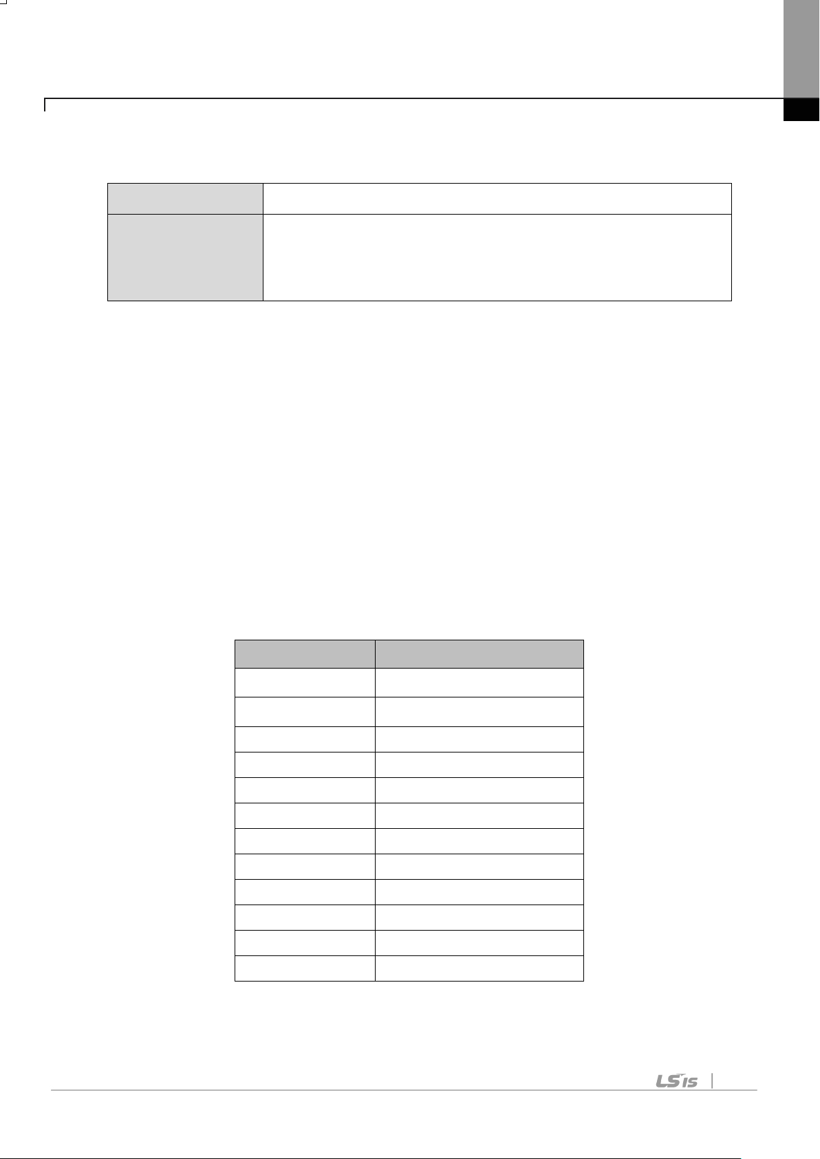
Chapter4. Inverter Parameter
Group
Group Number
Ad Group
3
Cn Group
4
In Group
5
OU Group
6
CM Group
7
AP Group
8
Reserved
9
Reserved
10
PRT Group
11
M2 Group
12
4.2.7 Para Control 1~8
CM-50 Number of Para Control setting
CM-51
~
Para Control 1~C ont rol 8 sett i ng
CM-58
It determines that what control information will be sent to inverter
through Profibus-DP communication.
Para Control 1 ~ 8 are set in the form of inverter address.
They set up the address for the common inverter area and the
inverter keypad parameter. If the keypad parameter address is
written, it will be saved in the form of 0x1000 + (‘Group number’ x
0x100) + (‘Code numbe r’).
For example, if A cc Time of No.3 at dr Group is set to Para Control1, it has to be set to 0x1103.
0x01 x 0x1000 + 0x01 x 0x100 + 0x03 (Dec 3) = 0x1103
dr Group 1
bA Group 2
19
Page 22
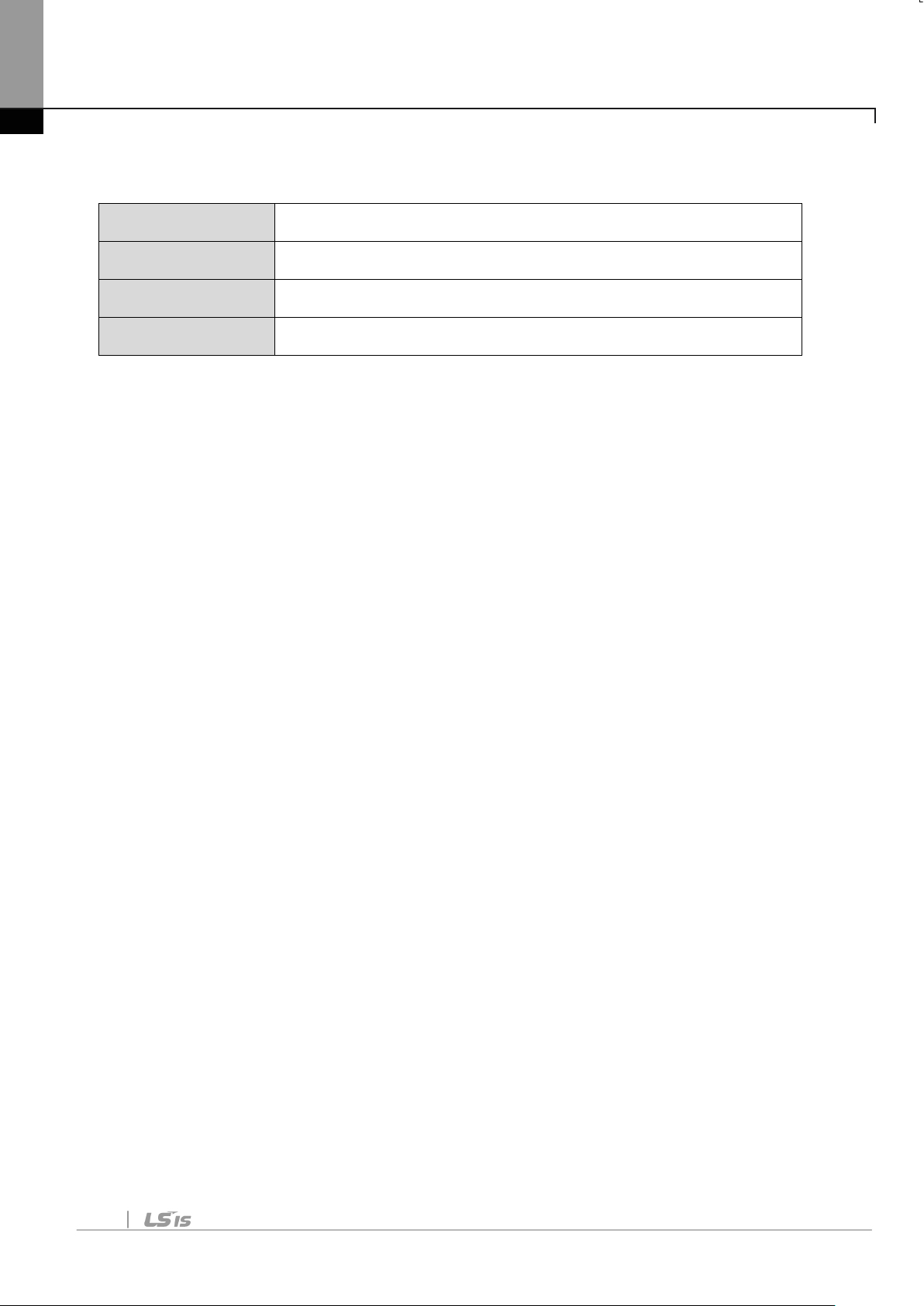
Chapter4. Inverter Parameter
4.2.8 Comm Update
CM-07 Station ID setting
CM-30 The number of Para Status setting
CM-50 The number of Para Control setting
CM-94 Comm Update
After changing Station ID, the number of Para Status and the
number of Para Control, set the Comm Update to ‘1’.
The changed values will be applied to Profibus-DP communication
module after setting Comm Update to ‘1’.
20
Page 23

Chapter 5. GSD File (Electronic Data Sheets)
Chapter 5. GSD File (Electronic Da ta Sheets)
GSD file contains the information of Profibus-DP communication
module. The profibus configuration software needs GSD file.
You can download GSD file from technical support on LSIS website.
(http://www.lsis.com)
21
Page 24

Page 25
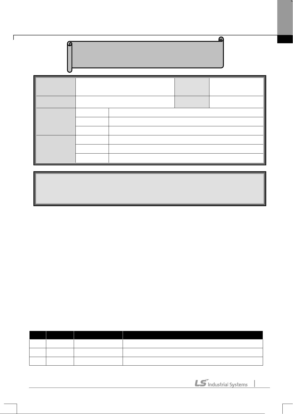
Warranty
Installation
Warranty
12 months after installation or 18 months after
manufactured when the installation date is unidentified. However, the
IN-WARRANTY service information
OUT-OF WARRANTY service information
No
Date
Edition
Changes
1
2012.05
First Release
2
2015.07
2nd Edition
Image changed
Warranty
Maker LS Industrial Systems Co., Ltd.
Model No. CPDP-S100
Name
Customer
Information
Sales Office
(Distributor)
Address
Tel.
Name
Address
Tel.
(Start-up)
Date
Period
Warranty period is
guarantee term may vary on the sales term.
If the defective part has been identified under normal and proper use
within the guarantee term, contact your local authorized LS distributor or
LS Service center.
The guarantee will not apply in the following cases, even if the guarantee
term has not expired.
Damage was caused by misuse, negligence or accident.
Damage was caused by abnormal voltage and peripheral devices
malfunction (failure).
Damage was caused by an earthquake, fire, flooding, lightning, or other
natural calamities.
When LS nameplate is not attached.
When the warranty period has expired.
Revision History
A
 Loading...