

Page 1

Manual ProtoMat M60
English, version 1.0
LPKF Laser & Electronics AG
Osteriede 7
D-30827 Garbsen
Telefon : ++ 49 - 51 31 - 70 95 - 0
Telefax : ++ 49 - 51 31 - 70 95 - 90
eMail : [email protected]
Homepage : http: //www.lpkf.de
Page 2

Copyright (c) 2000 LPKF AG
Distribution or reproduction of this manual and use of its content
permitted only with the written approval of LPKF AG. Right to make
modifications reserved. No liability is accepted for the content. In
particular, we accept no liability for damage caused by information given,
information absent, or erroneous information.
Trademarks: HP-GL is a registered trademark of the Hewlett Packard
Corporation. All other trademarks are registered by their owners.
2 ProtoMat M60
Page 3

Information on this manual
The information contained in this document may be modified without
prior notification. No part of this document may be reproduced or
transmitted for any purpose or in any form by any means, electronic or
mechanical, by photocopy, by recording or by information storage and
information retrieval systems without the express written permission of
LPKF.
We have taken great trouble to ensure the accuracy and completeness
of the information in this document. However, LPKF accepts no liability
for the use of the document, including breach of copyright or other
infringement against third parties which may arise from this.
It is the duty of the system owner to care for and plan these measures as
well as to control their execution. The owner especially has to ensure
that
• the system is only used as directed
• the system is only operated in perfect and functional
condition. Especially the function of the safty appliances
has to be checked regularly
• the necessary personal protectiv equipment for the
operating, maintaining and repairing personnel is available
and being used
• the operating manual is kept legible and complete at the
place of operation
• only sufficiently qualified and authorized personnel
operates, maintains and repairs the system
• this personnel is regularly instructed in matters of work
safety and environmental protection and is informed on the
operation manuel and especially the safety instructions
• all safety and warning notes or signs stay on the system and
are legible
ProtoMat M60 3
Page 4

Using this manual
I. Orientation
This manual is divided into the following chapters:
Safty notes
1.
Introduction
2.
General Information
3.
Setup
4.
Operating displays
5.
Computer-controlled functions
6.
Tools and accessories
7.
Milling and drilling
8.
Appendix
9.
Declaration of conformity
10.
Index
11.
II. Conventions used in this manual
Bold text
Illustrations
› Prompts for actions are identified with an arrow.
Italic sections
action.
Words printed in italics
Key inscriptions and menu terms are printed in
is used to emphasise important information.
are numbered. Example: Fig. 5
are used to indicate the reactions consequent on an
mark proper names
BOLD CAPITALS
III. Notes on the symbols used
Danger!
Caution!
damage.
This symbol is used to highlight danger to life or health.
This symbol is used to identify hazards which may cause
.
This symbol is used for notes intended to help you avoid faults in
Note:
operation or to help you improve your procedures.
4 ProtoMat M60
Page 5

III. Legend
Copper laminate: special, very thin base material used only for
laminating multilayer boards
Base material : Circuit board material coated with copper foil
Solder foil : special foil for cutting aperatures for the connections to
be soldered
BoardMaster
CurcuitCAM
: Machine control software
: Software for data preparation
IV. Target Group
This manual is written for people with basic knowledge in PCB
production.
ProtoMat M60 5
Page 6

Table of contents
1.0 Safety notes . . . . . . . . . . . . . . . . . . . . . . . . . 9
2.0 Introduction. . . . . . . . . . . . . . . . . . . . . . . . . 10
2.1 Characteristics of the ProtoMat M60
. . . . . . . . . . .10
3.0 General Information . . . . . . . . . . . . . . . . . . 11
3.1 Scope of supply
3.2 Optional accessories
3.3 Air-borne sound
3.4 Installation
. . . . . . . . . . . . . . . . . . . . . . . . . . . 11
. . . . . . . . . . . . . . . . . . . . . . . 11
. . . . . . . . . . . . . . . . . . . . . . . . . . . 11
. . . . . . . . . . . . . . . . . . . . . . . . . . . . . . .12
4.0 Computer-controlled functions . . . . . . . . . 13
4.1 Connection to a PC
4.2 Machine orientation
. . . . . . . . . . . . . . . . . . . . . . . .13
. . . . . . . . . . . . . . . . . . . . . . . .14
4.3 Displays and connections
4.4 Use of BoardMaster
. . . . . . . . . . . . . . . . . . . .15
. . . . . . . . . . . . . . . . . . . . . . . .16
5.0 Setup . . . . . . . . . . . . . . . . . . . . . . . . . . . . . . 17
5.1 Before switching on
5.2 Turning the system on
5.3 Switch-on instructions for high-speedcycle spindles
5.4 Changing a tool
5.5 After switching on
5.6 Function test with BoardMaster
. . . . . . . . . . . . . . . . . . . . . . . .17
. . . . . . . . . . . . . . . . . . . . . .17
17
. . . . . . . . . . . . . . . . . . . . . . . . . . .18
. . . . . . . . . . . . . . . . . . . . . . . . . .19
. . . . . . . . . . . . . . .19
6 ProtoMat M60
Page 7

5.7 HOME-Position and two-pin system
. . . . . . . . . . . .20
5.8 Programming the HOME position
5.9 Checking and correcting the HOME position
5.10 Making a new two-pin system
5.11 Producing a PCB with BoardMaster
. . . . . . . . . . . . . .20
. . . . .21
. . . . . . . . . . . . . . .22
. . . . . . . . . . .23
6.0 Tools and accessories . . . . . . . . . . . . . . . 25
6.1 Tools
6.2 Materials used for machining
. . . . . . . . . . . . . . . . . . . . . . . . . . . . . . . . . . . .25
. . . . . . . . . . . . . . . . .26
7.0 Milling and drilling . . . . . . . . . . . . . . . . . . . 28
7.1 Securing the PCB on the machine bed
. . . . . . . . .28
7.2 The mechanical working depth limiter
7.3 Functional elements on the mill/drill head
7.4 Drilling
7.5 Isolation milling
7.6 Contour milling in PCB material
7.7 Milling wide isolation channels
7.8 Front plate engraving
7.9 Milling layout films
7.9.1 Correction agents . . . . . . . . . . . . . . . . . . . . . . . . 36
7.9.2 Coloring milled films. . . . . . . . . . . . . . . . . . . . . . . 36
7.9.3 Coating removal. . . . . . . . . . . . . . . . . . . . . . . . . . 36
. . . . . . . . . . . . . . . . . . . . . . . . . . . . . . . . . . .31
. . . . . . . . . . . . . . . . . . . . . . . . . . . .32
. . . . . . . . . . . . . . .33
. . . . . . . . . . . . . . . .34
. . . . . . . . . . . . . . . . . . . . . . .34
. . . . . . . . . . . . . . . . . . . . . . . . .35
. . . . . . . . . .29
. . . . . . .30
7.10 Milling of solder mask foils
7.11 Drilling with the micrometer screw
ProtoMat M60 7
. . . . . . . . . . . . . . . . . .37
. . . . . . . . . . . .37
Page 8

7.12 Cleaning the PCB
7.13 Practical tips
37
. . . . . . . . . . . . . . . . . . . . . . . . . . . . .38
8.0 Appendix . . . . . . . . . . . . . . . . . . . . . . . . . . . 40
8.1 Maintenance
8.2 Lubricating the carriage guide wipers
8.2.1 Carriage guide wipers of the X-axis . . . . . . . . . . . 42
8.2.2 Oiling the rear wipers . . . . . . . . . . . . . . . . . . . . . . 43
8.2.3 Oiling the front wipers. . . . . . . . . . . . . . . . . . . . . . 43
8.3 Serial port SERIAL 1
8.4 Serial port SERIAL 2
8.5 Motor connection
. . . . . . . . . . . . . . . . . . . . . . . . . . . . . .40
. . . . . . . . . . .42
. . . . . . . . . . . . . . . . . . . . . . .43
. . . . . . . . . . . . . . . . . . . . . . .44
. . . . . . . . . . . . . . . . . . . . . . . . . .44
8.6 Mill head connection
8.7 EPROMs
. . . . . . . . . . . . . . . . . . . . . . . . . . . . . . . .45
8.8 Fuses, commuting the device voltage
8.9 The LPKF ProtoMat M60 Commands
8.9.1 Command structure . . . . . . . . . . . . . . . . . . . . . . . 48
8.9.2 HP-GL standard commands. . . . . . . . . . . . . . . . . 49
8.9.3 Special commands. . . . . . . . . . . . . . . . . . . . . . . . 50
8.9.4 Special command for the high-speedcycle spindle52
8.9.5 Direct commands . . . . . . . . . . . . . . . . . . . . . . . . . 52
8.10 Inventory of available tools
8.11 Concluding remarks
8.12 Declaration of conformity
. . . . . . . . . . . . . . . . . . . . . . . .45
. . . . . . . . . .45
. . . . . . . . . .48
. . . . . . . . . . . . . . . . . .53
. . . . . . . . . . . . . . . . . . . . . . .54
. . . . . . . . . . . . . . . . . . .55
8.13 Konformitätserklärung
. . . . . . . . . . . . . . . . . . . . .56
9.0 Index . . . . . . . . . . . . . . . . . . . . . . . . . . . . . . 57
8 ProtoMat M60
Page 9

1.0 Safety notes
Safety notes
In order to be able to guarantee the safe operation of the system
the user must have read this manual and especially the safety
precautions printed in bold types!
• Never reach into the machine while it is running!
• Remember that the machine changes speed automatically
during the process!
• Only change the tool when the mill/drill motor is not
spinning!
• Insert the tool into the clamping device as far as it will go!
• Never operate the control PC simultaneously when working
with the device!
• Operator with longer hair must wear a hair net!
• If you modify the equipment yourself, the equipment's safety
can no longer be guaranteed and no guarantee claims can
be accepted!
• Please take note that some materials may produce
cancerogenous dust or hazardous gases. Ask your supplier
of the materials.
• Always work with the vacuum device!
• When using chemicals please take note of the safety notes
on the containers or separate security sheets delivered with
them!
• Keep the workplace tidy.
ProtoMat M60 9
Page 10

Introduction
2.0 Introduction
The LPKF
be used to produce prototype PCBs and gravure films, and for engraving
aluminum or plastic.
Familiarity with the
M60 is essential for operation of the machine. Operation of the LPKF
ProtoMat
exclusive operating interface for the LPKF
from the serial port of a PC.
In order to make any guarantee claims, if necessary, it is absolutely vital
to follow the instructions of this manual before putting the machine into
operation. For machines exported to other countries of the European
Community the guarantee conditions of the corresponding country apply.
ProtoMat
M60 is described in the LPKF
M60 mill/drill unit is a circuit board plotter which can
BoardMaster
driver program of the LPKF
BoardMaster
ProtoMat
Manual. The
M60 is controlled
ProtoMat
2.1 Characteristics of the ProtoMat M60
Voltage 200-240V (or 100-120V)
Power consumption 200VA
Speed of high-speedcycle
spindle max.
Weight ca. 25 kg
Drilling performance max. 60 strokes/min
Resolution (smallest step) 0.0079375mm
Operating data:
Humidity 60% max.
Temperature: 15-25°C
60000/min
10 ProtoMat M60
Page 11

3.0 General Information
3.1 Scope of supply
General Information
• 1 LPKF
• 1 null modem cable (LPKF
AT- Adapter 9/25-pol
• 1 set of accessories (Drafting Tape, Allen wrenches, alignment
pins, tweezers, brush, 7 mm wrench, 2 red two-pin strips, 2
alignment drill 2,95 mm)
• 1 power cable
• Inserting tool for alignment pins
• This manual
ProtoMat
M60 machine unit with integrated electronics
ProtoMat
M60 control unit-computer),
3.2 Optional accessories
The following accessories can be supplied for the LPKF
• Vacuum system with fine filter. The fine filter is essential in
particular when handling materials containing glass fiber, such as
for FR4 base material.
• Noise and dust guard hood
• LPKF
AutoSwitch
Automatic switch for the vacuum cleaner. With this option can
over the mill/drill spindle, the vacuum cleaner switch on and off.
.
ProtoMat
M60:
• LPKF
• Integrated milling head lighting
AutoContac
Integrated through-hole plating using a dispenser and a special
conductive paste capable of being soldered
3.3 Air-borne sound
The continuous sound level at the work place during operation is 71 dB
(A). This value does not include the vacuum unit.
ProtoMat M60 11
Page 12
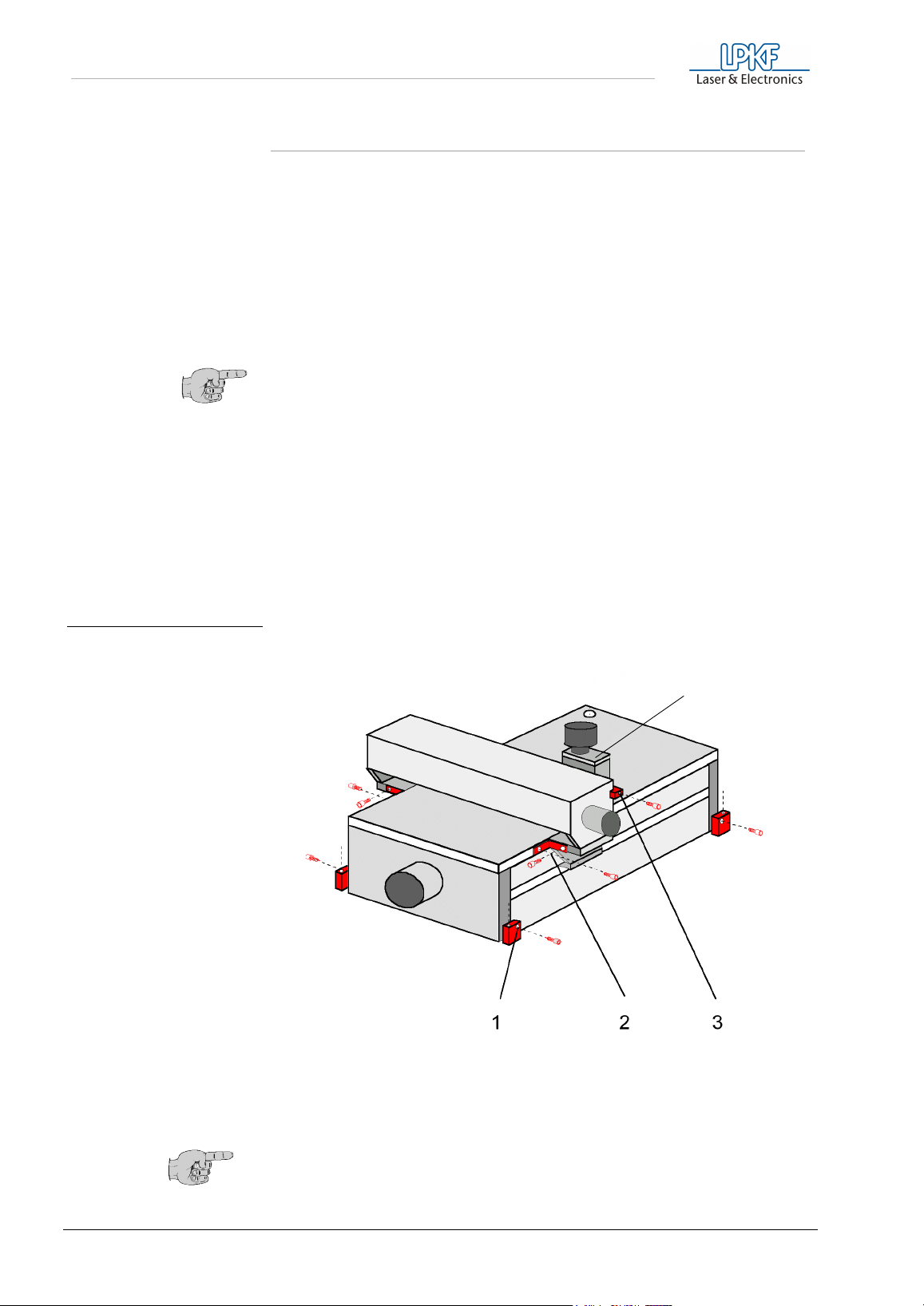
General Information
3.4 Installation
fig. 1: Transport safety devices of
the LPKF ProtoMat M60
› Unpack the LPKF
ProtoMat
M60 carefully (for detaching the security
screws see Fig. 1 on page 12). Then loosen the transport safety
devices. These devices are marked red and are located:
• Locking of the X-axis - 2 aluminium elbow joints (safety device 2)
• Locking of the Y-axis - directly at the head to the left (safety
device 3)
• Locking of the Z-axis - Allen screw (safety device 4)
Note: The equipment must stand on a flat and firm base in order to
work properly!
› Set up the circuit board plotter so that the connecting cables to the
electronic unit can move freely.
› Connect the LPKF
ProtoMat
M60 to the computer with the null
modem cable supplied with the system (COM1 or COM2).
› Plug the LPKF
ProtoMat
M60 control unit into the electricity supply
› Fit the Vacuum to the adapter (suitable for stay tube no. 111124 of a
Nilfisk industrial vacuum unit).
- Attaching the machine safely to the transport support
1
- Securing the X-axis
2
- Securing the Y-axis
3
- Securing the mill/drill head
4
4
Note: Keep all transport safety device and packing and mount them
accordingly if the machine is to be shipped.
12 ProtoMat M60
Page 13
4.0 Computer-controlled functions
4.1 Connection to a PC
Computer-controlled functions
The LPKF
is the INPUT to the system and is used for connection to the controlling
computer (PC). The second interface (SERIAL 2) is an OUTPUT and is
provided for future applications.
The LPKF
interface on the computer with the RS232 cable supplied.
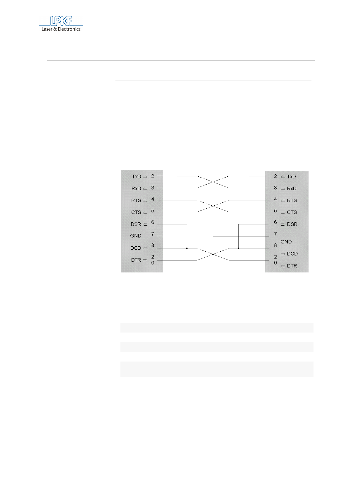
The RS232 cable (null modem) for the LPKF
plotter is wired as follows:
ProtoMat
ProtoMat
M60 has two serial interfaces. The first (SERIAL 1)
M60 control unit's SERIAL 1 is connected to a serial
ProtoMat
M60 circuit board
The cable shield ground is connected only on the PC side (port).
The following parameters must be observed:
Baudrate 9600
Parity None
Datenbit 8
Stopbit 1
Hardwarehand-
shake
FIFO-Buffer off
If the DOS driver is used the PC's serial interface is initialized with the
DOS command
must be initialized under Windows using Main/Control Panel/Ports.
Mode Com1:96,N,8,1
. If
BoardMaster
is used, the port
ProtoMat M60 13
Page 14
Computer-controlled functions
4.2 Machine orientation
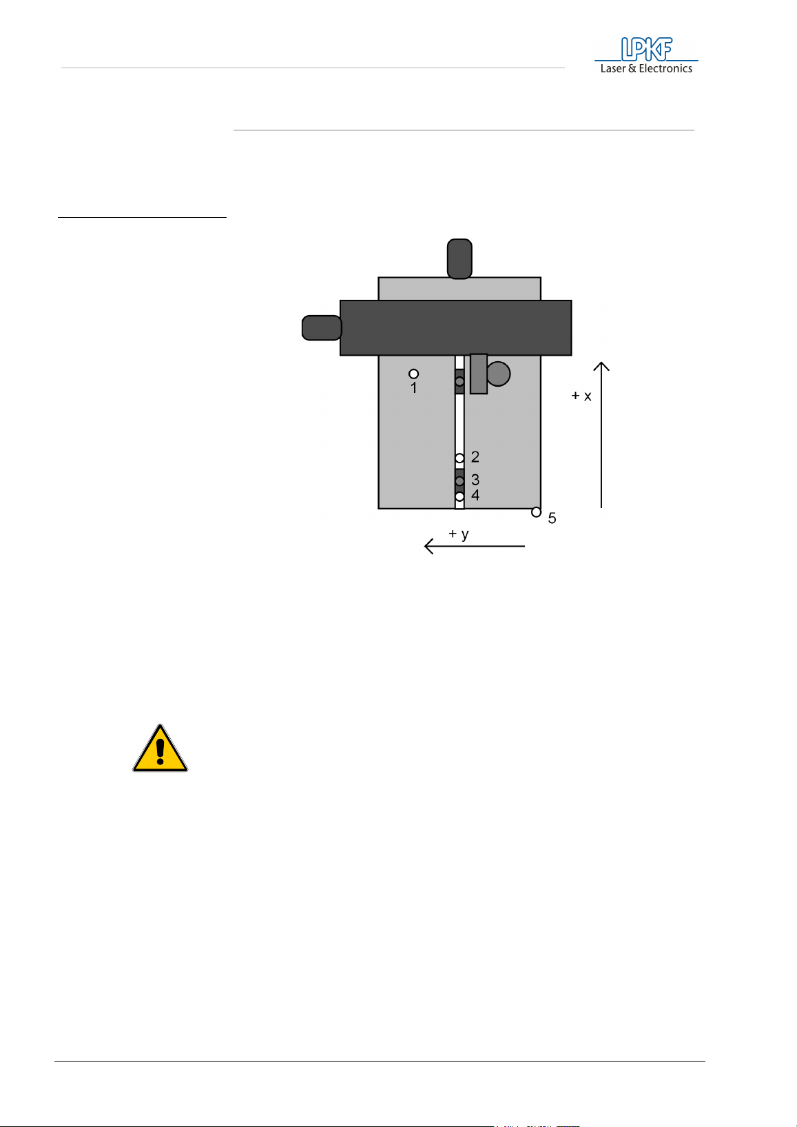
Description of the main machine positions:
fig. 2: LPKF ProtoMat M60: the x-
axis is the longer direction of
movement
- PAUSE position:
1
The machine will move to this point to load or turn the material to be machined.
- HOME position:
2
This is the relative 0.0 position and MUST lie on the machine mirror (X) axis (two-pin
system) and serves as the reference X=0,Y=0 position for the programm BoardMaster.
- Two-pin slide with hole for alignment pin.
3
- Reference pin for front two-pin strip
4
- Tool change position (absolute zero position). The tool is changed here.
5
Danger! Keep fingers and any other items out reaching into the
area of movement!
14 ProtoMat M60
Page 15
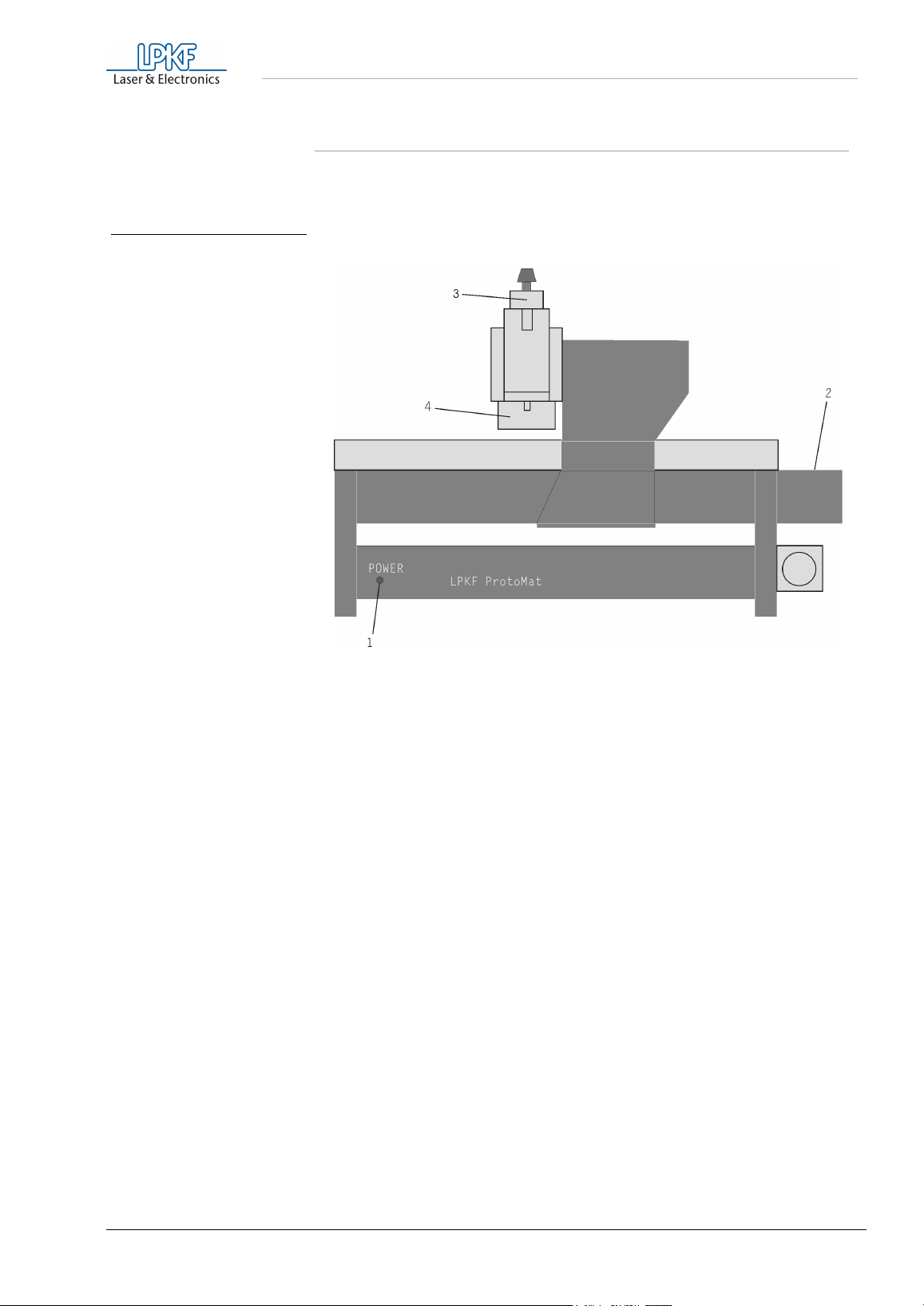
fig. 3: Front LPKF ProtoMat M60
Computer-controlled functions
4.3 Displays and connections
Description of the front panel:
1- Operating display of the integrated machine control SMCU
2- X motor
3- High-speedcycle spindle motor
4- Working depth limiter
ProtoMat M60 15
Page 16
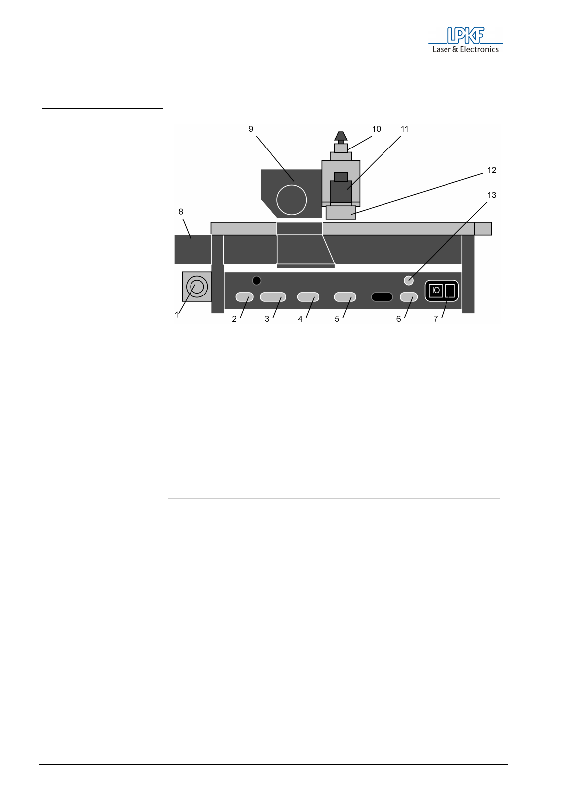
Computer-controlled functions
Description of the rear panel:
fig. 4: Rear view of LPKF ProtoMat
M60
- Vacuum connection
1
- Output Serial interface (9-pole) for controlling optional
2
equipment
- Input Serial interface (25-pole) for connection to
3
PC serial port
- X motor connection
4
- Y motor connection
5
- Mill/Drill head connection
6
- On/Off switch, power cord connector and fuses
7
- X motor
8
- Y motor
9
- High-speedcycle spindle motor
10
- Solenoid
11
- Working depth limiter
12
- Connection of high-cycle
13
spindle
4.4 Use of BoardMaster
Data required to drive the plotters are generated in
CircuitCAM
stored in files with HP-GL format or as LPKF binary files (LMD format).
BoardMaster
is used for reading the files, decoding plot commands and
modifying them for the specific LPKF System being driven. The drivers
use the HP-GL or LMD data and add important, machine specific
functions such as scaling, motor control, etc. The LPKF
ProtoMat
circuit board plotters respond to HP-GL commands. The drivers provide
additional capability such as step and repeat, move, rotate, etc.
All LPKF circuit board plotters are driven via an asynchronous interface
(RS232C). In the case of the LPKF
ProtoMat
M60, it is operated at
baud, 1 stop bit, 8 data bits, no parity and hardware handshake
configuration of the computer’s serial interface has to be accordingly set
within the system control of Windows. The FIFO-buffer has to be
switched off.
and are
M60
9600
. The
16 ProtoMat M60
Page 17
5.0 Setup
Setup
5.1 Before switching on
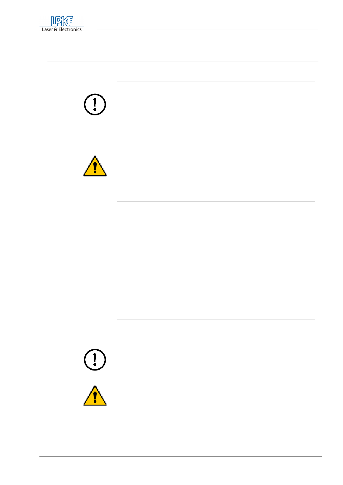
Caution! Be sure the voltage set at the machine corresponds with
the line voltage: If not, continue at „Fuses, commuting the device
voltage“ on page 45.
Before switching on, all items are to be removed from the machine and
its range of movement. Alignment pins are not allowed to jut out from the
base material. Alignment pins serves to fix, and by the twirl of the basematerial as reference point of the brush mirror.
Danger! Never reach into the machine while it is running!
5.2 Turning the system on
The following switching on order is useful, but not essential:
Computer
1.
LPKF
2.
3.
If for some reason it should be necessary to switch the machine off and
on again, then change to the
BoardMaster
initialization parameters like speed ranges, dwell times positions and so
on are again transmitted to the machine.
ProtoMat
Start the
BoardMaster
program and click on OK. Through all necessary
M60
program
MACHINE/SETTINGS
window of the
5.3 Switch-on instructions for high-speedcycle spindles
A tool must always be placed in the shaft of the high-speedcycle spindle
when the machine is switched on. The collet must always be closed and
the knob of the high-speedcycle spindle must be in itsist top position,
otherwise the spindle is blocked and the motor driver can be overloaded.
Caution! The Danger of spindle can be damaged if it operated
without a tool inserted!
Danger! Do not operate with the tool clamp before the spindle is
standing absolutely still!
ProtoMat M60 17
Page 18
Setup
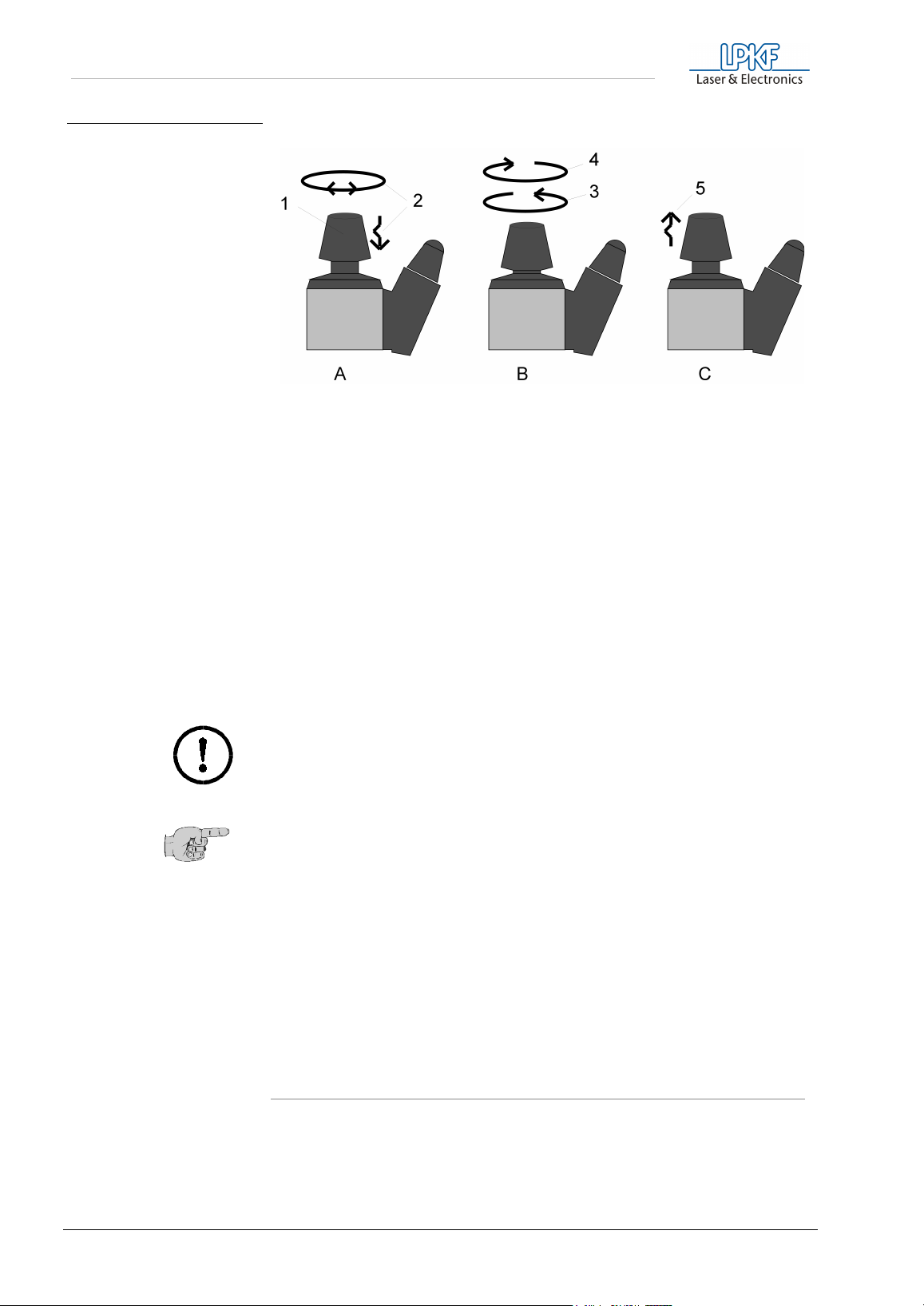
fig. 5: Operating the collet of the
high-speedcycle spindle
Knob in normal position, spindle is running freely. Push the knob
A)
(1) down until it is engaged in order to open or close the collet.
Hold the head up to avoid damaging the tool in the collet. Tight so
that a tool that might be inserted will not be damaged. If
necessary, turn the knob slightly to the right or to the left (2) when
pushing it down.
B) Caution
: In this position collet and spindle are blocked and the
drive electronics may be damaged if the motor is turned on. In
order to open the collet, turn the knob counter-clockwise (3). To
close, turn the knob clockwise (4). Do not turn the knob too tightly.
Bring knob back to normal position (top) (5). The spindle can now
C)
run free again. Spindles of some manufacturers are jumping back
into the normal position by themselves.
Caution! Only operate the spindel with the vacuum cleaner
switched on.
Note: During set-up take note that the bearings of the highspeedcycle spindle have to be run in first after a longer period of
standstill (several months) or after transport. During initial set-up
the spindle should run at 10 000 rpm for several hours.
Normal warm-up of 3 to 10 minutes (at 20 000 rpm) of the spindle is
automatically controlled by
BoardMaster
. The duration of this warm-up
depends on the length of time the system has been off. During warm-up
no speeds exceeding 20,000 rpm will be allowed. Programmed speed
above 20,000 rpm will be allowed after the warm-up time.
5.4 Changing a tool
For changing a tool there is to be considered, that the tool after the
opening is introduced up to the plot in the tool clamp, before the tool
clamp is closed again. Befor handling the tool clamp you must read
chapters „Switch-on instructions for high-speedcycle spindles“ on
page 17.
18 ProtoMat M60
Page 19
Setup
5.5 After switching on
When it has been switched on, the equipment moves to limit switches -X
and -Y, and the system then halts in the tool change position. It is then
able to accept commands from the machine drivers. If the equipment
does not move when it has been switched on, check the following:
Is the POWER LED on (is on only after successful initialization)?
1.
Are all cables properly inserted ?
2.
If necessary, check the fuses at the input power connection!
3.
5.6 Function test with BoardMaster
Danger! Make sure that nothing is no other persons are in the
machine operating area when the first functional test is taking
place!
First check that the serial interface used is set to
bits, 1 stop bit, no parity bit and hardware handshake and FiFObuffer off
been selected in
the
Now using
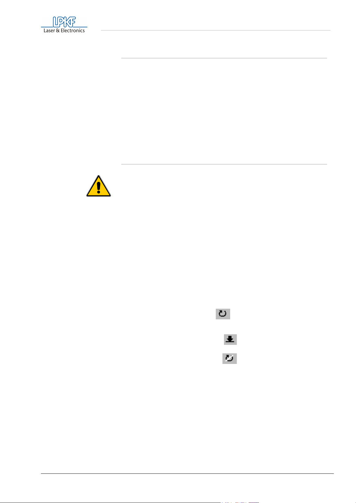
› The correct tool must be declared (clicked on) in the window
› Before the motor can be switched on, the milling head has to be
› turn on the motor, to click of (first the motor will turn at a
› raise/lower the head, to click of
› switch off the motor, to click of
› move the head manually using the cursor keys on the
If the equipment does not move, check the interface configuration, the
connecting cable as well as the PC interface.
. Also check that
BoardMaster
BoardMaster
ASSIGNMENT
moved out of the tool-change position a few inches using the cursor
key.
maximum of 20,000 rpm, warm up phase)
function bar.
Manual if you need help.
BoardMaster
CHANNEL
under
:
and the correct interface have
MACHINE CONNECT...
9600 baud, 8 data
Consult
TOOL-
BoardMaster
ProtoMat M60 19
Page 20

Setup
5.7 HOME-Position and two-pin system
The HOME position must be on the machine's X axis (two-pin system) to
guarantee alignment of a double sided board. The data for the bottom
side of a PCB is mirrored around the X axis and therefore the board
must also be rotated around the X axis to maintain registration.
Inaccuracies in the HOME position result in a displacement during
machining of double-sided boards after the rotation.
Note: The two-pin system is parallel only for the current position of
the two-pin strips. The front two-pin slide must be placed against
the pin in the groove (reference). If base material of different sizes
is used, an additional hole must be drilled in the strip of the back
for every format. To do this, move from the home position in
direction of the rear strip, displace it to the desired position and
drill an additional hole by hand, using the 2,95 mm drill. The
position of the new holes should recorded or marked at the plotter.
This will help when drilling the reference hole in various size
material.
5.8 Programming the HOME position
The home position needs to be programmed on new equipment and
when the system has been moved.
The HOME position of the LPKF
mirror (X) axis (the two-pin system with the red plastic slides) for
machining double-sided base-material. To do this, proceed as follows:
› Start
› Click
› Now select
› Activate
› Make sure that SMCU is selected.
› Now
The equipment travels to all four end positions, and then stops in the
ZERO position (tool change position). The movement range thus
determined is displayed under SIZE and stored when the MACHINE
SETTINGS..dialog box is left. For more detailed information see the
BoardMaster Manual.
A two-pin system has already been set up at the factory. The HOME
position x and y coordinates is delivered with the machine on the
enclosed paper (see driver diskette). They should now be entered under
Home in
BoardMaster
CONFIGURATION
SETTINGS..
UNLOCK
INITIALIZE
BoardMaster
so that you can make entries in this window.
must be clicked.
.
ProtoMat
in the menu bar.
M60 must be precisely on the
If the coordinates are not known, the two-pin system must be drilled
again. To do this, see the section „Making a new two-pin system“ on
page 22.
Click OK to close the
BoardMaster
time
BoardMaster
20 ProtoMat M60
. The new values are saved in an .INI file wich is read each
MACHINE SETTINGS
is called.
dialog box and quit
Page 21
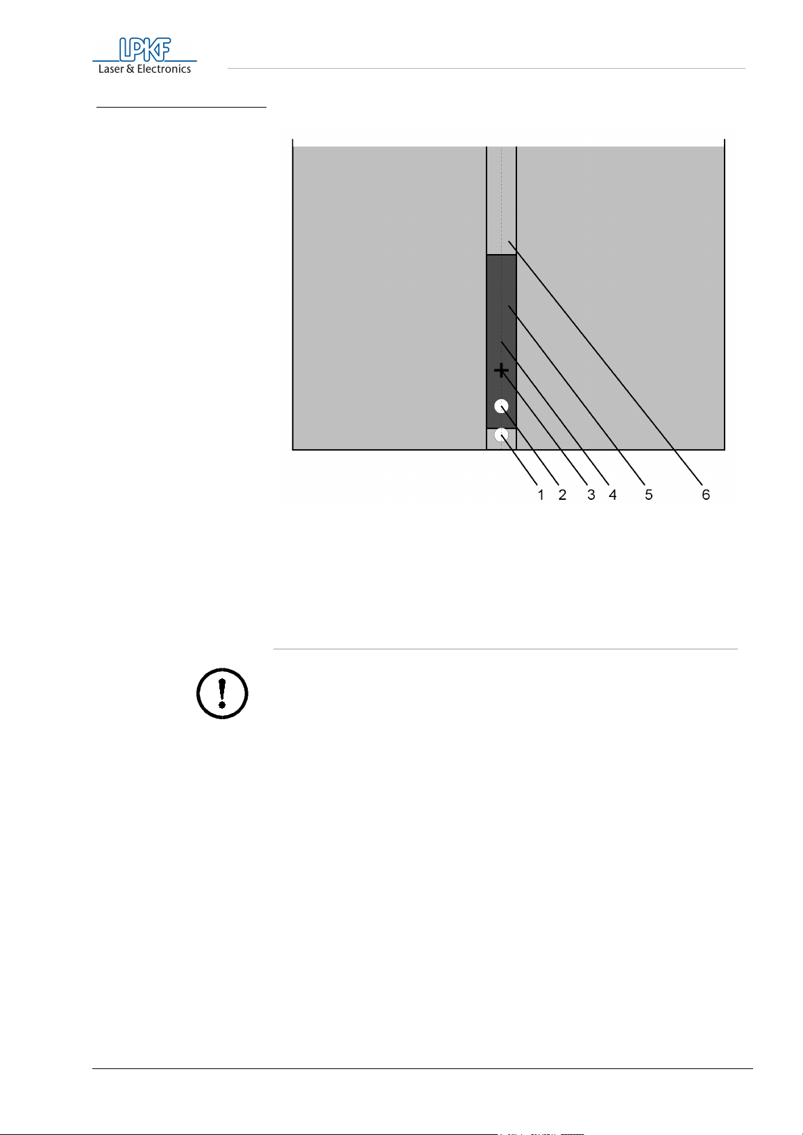
fig. 6: Front stripe of the two-pin
system
Setup
- reference pin
1
- front alignment pin
2
- HOME position, min. 10 mm distance to the alignment pin
3
- mirror axis
4
- two-pin stripe
5
- two-pin groove
6
5.9 Checking and correcting the HOME position
Caution! Bevore beginning you must read the chapters „The
mechanical working depth limiter“ on page 29 and „Changing a
tool“ on page 18.
› Make alignment holes in double-sided base material.
› Fix the material and the drilling base (2 mm) on the base plate with
the help of the alignment pins (see too the section „Securing the
PCB on the machine bed“ on page 28).
› Drill a hole at the HOME position with a 0.7 mm drill.
› Move the mill/drill head to the PAUSE position.
› Turn the base-material around (about the X axis).
› Move to the HOME position, move to the tool change position and
insert a universal milling cutter. When the tool has been changed,
the mill/drill head automatically returns to the HOME position.
› Mill a channel over the hole manually in the X direction, without
moving in the Y direction.
› Check visually that the milled channel passes precisely through the
center point of the hole.
ProtoMat M60 21
Page 22

Setup
› If the milled line does not run exactly through the center point, the
HOME position must be corrected by half the difference. This can be
done directly by changing the home position in
SETTINGS..
dialog box.
MACHINE
› After making a correction, the movement should be repeated as a
check.
5.10 Making a new two-pin system
The alignment holes in the red two-pin strip become larger over time due
to use and top to bottom alignment will suffer. You must then drill new
holes in the slides. If after a certain time there are too many holes in the
slides, the two-pin strips must be changed.
Danger! Take note that sharp tools are involved and that they may
be hot. In order not to hurt yourself because of chips always work
with the vacuum system switched on!
To make a new two-pin system, proceed as follows:
› First press both two-pin strips into the machine groove, with the front
two-pin strip pushed against the reference pin to the front of the
groove. The distance between the two two-pin strips should be about
the size of the base material in the X axis.
› Fit a drill measuring 2,95 mm in diameter so that the distance
between the base plate and the drill point is about 0.5 mm (Under the
base material you can put a 0.5 mm thick base). This is the only time
a tool is not inserted into the collet as far as it will go. The speed of
the drill must be changed to 25.000 rpm in
BoardMaster
.
› Move the plotter head in +x direction for about 30 mm and define this
positionas the new HOME position (set HOME, see
CONFIGURATION
)
MENU
› Move the mill/drill head to HOME and then to the front two-pin strip
(Pull the alignment pin before, in order to avoid the drill from
breaking off). Then manually drill a hole about 4 mm deep in the
approximate center by pressing down the drill head (before, choose
in menu bar
DRILLING PLATED
). Afterwards, do not move the mill/
drill head position in the Y direction.
› Move in the X axis a known amount to the second, rear two-pin strip
(from the first hole, 287 mm) and drill a hole about 4 mm deep there
too. By no means move in the Y-direction.
› Now position the drill tool in the drill chuck as far as it will go.
› Move the mill/drill head to the side. Insert two alignment pins in the
holes now made in the two-pin strip. Check that the pins are firmly
inserted as any play affects alignment accuracy.
› Mark old holes with a felt pen so they cannot be confused with the
new ones.
22 ProtoMat M60
Page 23
Setup
› Position the previously drilled base material and drilling base over
the alignment pins. The holes in the base material and the copper
clad should have been drilled using the system and at the same
distance apart as the alignment pins so the plastic strips do not have
to be moved.
› Now fix the base material thus positioned with adhesive tape on all
four sides.
5.11 Producing a PCB with BoardMaster
The job to be carried out must already be loaded or prepared in
BoardMaster
. For example, the data from the
CircuitCAM
used.
A further requirement is that the HOME position was programmed
precisely as described.
Caution! Bevore beginning you must read the chapters „The
mechanical working depth limiter“ on page 29 and „Changing a
tool“ on page 18.
tutorial can be
Danger! Take care when handling the tools! Danger of cutting! Do
not forget to switch on the vacuum system during machining!
› Move to the PAUSE position using
PAUSE
).
BoardMaster (GO TO...,
› Fix the base material using alignment pins as described in the
section „Securing the PCB on the machine bed“ on page 28.
› Using
BoardMaster
, move to the left corner (-x, -y) of the base
material so that the working depth limiter does not quite touch the
adhesive tape.
The project must be visible in BoardMaster as light gray on the dark
gray machine surface.
› If applicable, move the project by means of
PLACEMENT
so that the
graphics data is completely on the material. In the menu the position
can be selected manually. It can also be clicked on the icon
on a corner of the projekt, so that the machine exactly approaches
this point.
› Select the first machining phase i.e.
› Drill data is selected with
ALL+
.
DRILLINGPLATED
.
Selected data is shown brighter.
› Switch on
BoardMaster
› Press
START
AUTO-MOTOR-ON
).
.
( ) (motor key on right in
BoardMaster requests the tool needed for the machining phase by
traveling to the tool change position and then switching the motor off
automatically.
ProtoMat M60 23
Page 24
Setup
The tool can be removed by using the enclosed tweezers from the shaft
of the motor.
› Insert the ordered tool up to the limit and fix it.
› Acknowledge the tool change with OK.
The motor switches on and the first hole diameter of the drill phase is
carried out.
› Once the holes of the current diameter have been made, the next
tool is requested and changed in the same way.
› When the drill phase is complete, mill phase
MILLINGBOTTOM
is
selected after any through-plating.
› The milling depth should now be set. To do this, click
CUTTER
in the
TOOL
combo box.
UNIVERSAL
The head travels to the tool change position.
› Insert the universal milling cutter and, with the arrow keys, move
over the base material, but not over the project, in
BoardMaster
.
› Set the step size manually (approx. 10 mm) . Switch on
the milling/drilling motor . Move down the raise/lower plotter
head and move with the arrow keys .
Check the milling channel (if necessary, with handmicroscope) and
correct the milling depth correspendingly (see chapter „The
mechanical working depth limiter“ on page 29).
› Switch on
BoardMaster
AUTO-MOTOR-ON
).
› The mill data for the component side is now selected with
Machining is started with
( ) (motor key on right in
START
.
ALL+
.
› Move to the pause position and turn the material.
› Select and carry out the
› If required, select the
CUTTING
MILLINGTOP
mill phase and machine with a
mill phase.
contour milling cutter.
› Move to the pause position, remove the PCB and proceed as
described in the section „Cleaning the PCB“ on page 37.
24 ProtoMat M60
Page 25
6.0 Tools and accessories
6.1 Tools
Tools and accessories
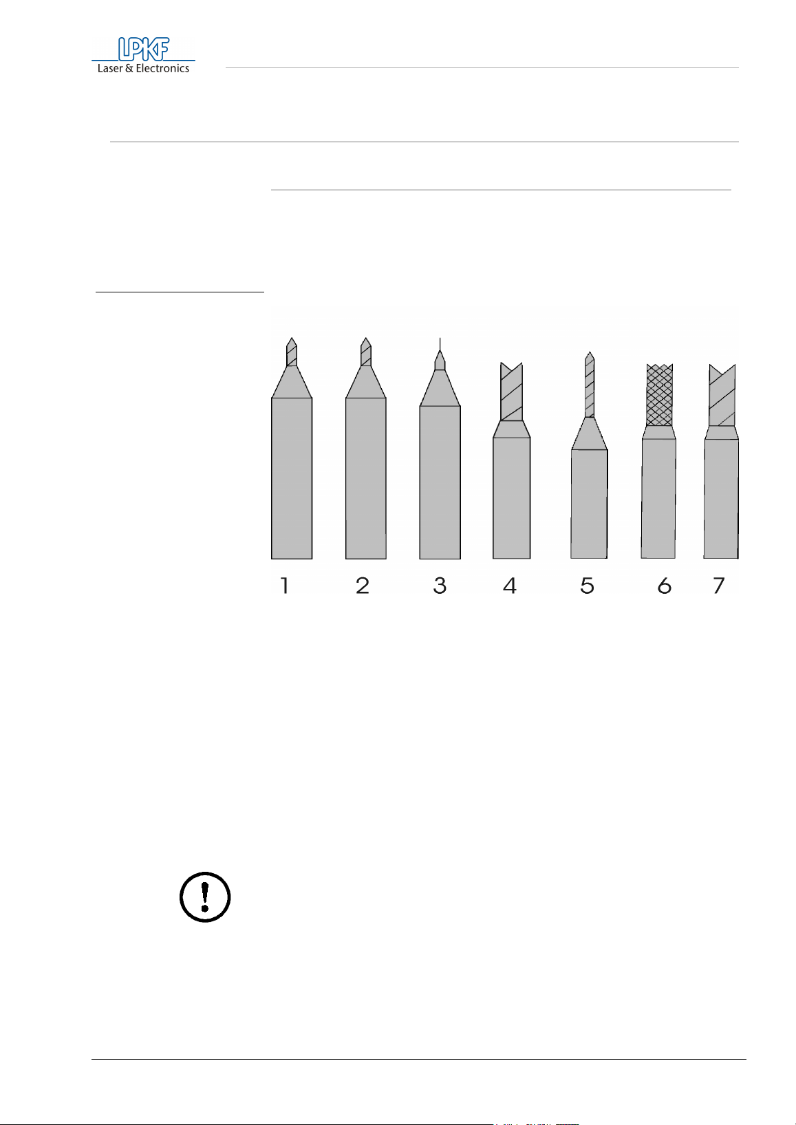
fig. 7: LPKF tools for circuit board
plotters
The tools for the LPKF
ProtoMat
M60 come in two different lengths.
Tools used to machine the material surface (milling and engraving) are
36 mm long for 1/8" and tools used for drilling or contour milling are 38
mm long for 1/8" collets. The following tools are available.
- Universal Cutter for milling of isolation-canals and to the front
1
- Micro Cutter: for milling isolation channels of 0.1 - 0.2mm
2
- End Mill (HF) produces rectangular isolation channels of 0,15
3
- End Mill for engraving of aluminums and to the milling of
4
- Drill Bit Cylindrical special tool to the drilling of base
5
- Contour Router to the contur routing of conductor plates as well
6
- End Mill to the contur routing as well as milling machine of
7
panel-engraving of 0,2-0,5 mm, according to
depth setting, length 36 mm.
(depending on the depth setting ), length 36mm
mm, 0.25mm or 0,4 mm width, length 36 mm
wide isolations, different diameters, length 36
mm.
material (reinforcedf), different diameters.
as molding machines of outbreaks, with chip
removal downward (downcutting), different diameters, length 38 mm
outbreaks in aluminums, HF-and microwavematerials. Length 38 mm
Caution! Execute a tool change only in defined positions!
The tools must always be inserted in the tool fixture as far as they will
go. Otherwise the working depth will be incorrect. In certain
circumstances, this can even result in damage to the machine base
plate.
Tweezers are supplied for tool insertion and removal.
ProtoMat M60 25
Page 26
Tools and accessories
6.2 Materials used for machining
In general all base materials supplied by LPKF can be used for
machining. You are free to machine all other materials at your own risk.
Take into consideration the notes of the manufacturers.
However, the most basic phenol resin qualities (FR 2) can adversely
affect milling quality.
Glass fiber reinforced epoxy material (FR 4 or G 10) can be a health
hazard due to the milling dust produced (allergies, risk of cancer). Tool
service life is also substantially reduced.
Danger! Never work without extractor!
We recommend epoxy material without glass fiber (FR 3). With top
milling quality and a high tool service life, no disadvantages with regard
to FR 4 are known other than a slightly reduced mechanical strength
bearing capacity (breakage). This drawback should not be of any
significant importance for prototype boards plates unless particularly
heavy components are to be mounted. The adhesive quality of the
copper on the base material is mostly slightly reduced which might lead
to the removal of smaller pads.
Normally, a total thickness of 1.5 mm and a Cu thickness of 35 µm are
used. With 17 µm material even fine milling channels can be engraved at
a higher packing density. For galvanically through-hole-plated, doublesided PCBs, 5 - 17 µm Cu thickness is used to prevent an excessively
thick copper layer after galvanic copper application.
With 70 µm material, compromises must be made when setting milling
depth. I.e. a deeper milling depth results in wider milling channels of 0.5
to 0.7 mm.
Special base materials with a thicker copper layer of up to 300 µm can
no longer be machined with the LPKF universal milling cutter. Contour
milling cutters or special tools are needed for this. In these cases, we
would ask that you consult us and send sample material so that tests
can be carried out if appropriate.
Teflon materials can be machined, but the following points must be
borne in mind:
• As the material is very soft and therefore often extremely uneven,
a constant milling width often cannot be maintained unless, so
the material is should be smoothed first.
• Because the material is so soft, it is not possible to mill such as
fine isolation tracks as in epoxy material.
Danger! Machining Teflon might produce hazardous gases! Protect
Teflon from overheating!
26 ProtoMat M60
Page 27
Tools and accessories
The following material has proved particularly successful as material for
HF and microwave applications: RT/Duroid types 5870, 60XX, RO
4XXX, oder TMM-X.
A drilling base is indispensable for all machining processes on PCB
material. With it, PCBs cannot be drilled through without damaging the
machine. The drilling base can be made simply of cardboard and should
be 2 mm thick.
Note: Use two shims for the processing of material with a diameter
< 0.8 mm.
Material supplied by LPKF and suitable for machining:
FR3-material: engraving, drilling, milling
FR4-material : engraving, drilling, milling
Engraving film: engraving
Material suitable for machining but not yet supplied by LPKF:
Different HF applications: engraving, drilling, milling
Danger! Keep from overheating, hazardous gases may be
produced!
Danger! When working with materials containing glass fibers there
might be produced cancerogenous dusts. Therefore only work with
vacuum system switched on!
Danger! When working with unknown materials cancerogenous
dusts or hazardous gases may be produced. Ask your supplier or
the manufacturer before starting with the machining.
ProtoMat M60 27
Page 28
Milling and drilling
7.0 Milling and drilling
7.1 Securing the PCB on the machine bed
› Make 3.05 mm alignment holes in the base material and backing
material spaced the same distance as the alignment pins. This can
also be done with any upright drilling machine. Take into
consideration that the diameter decreases during galvanic throughplating process so do not plate these holes.
› Move the mill/drill head to the PAUSE position. Insert alignment pins
in the front and rear two-pin strips but, even so, check that the front
two-pin strip is pushed forwards against the reference pin in the
machine groove.
› Position the pre-drilled base material and drilling base over the
alignment pins. The format of the base material should be selected in
a way that the two-pin slides do not have to be moved by more than
10 mm, as otherwise the two-pin system precision decreases.
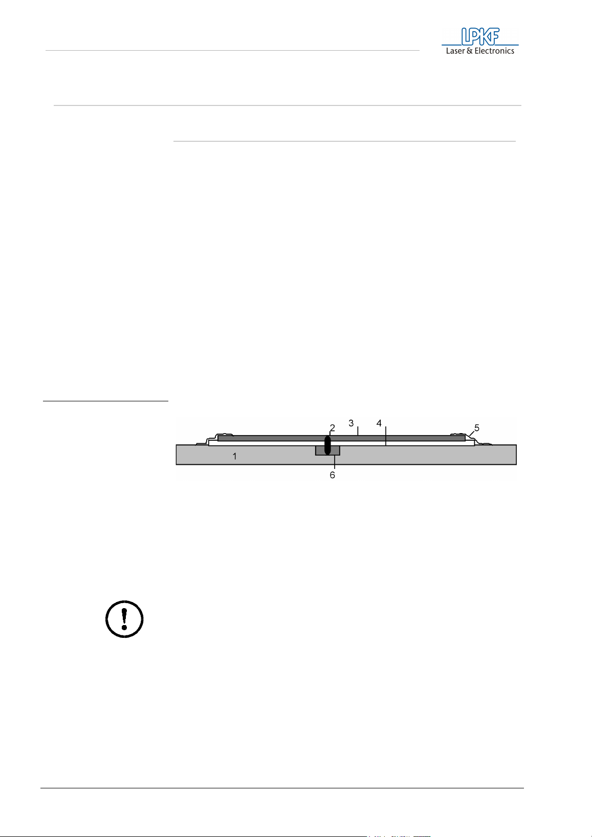
fig. 8: Securing the PCB
› Now secure the base material in position with drafting tape (masking
tape is not recommended because it leaves a residue) on all sides.
This prevents the corners of the PCB turning upwards.
- Machine bed (aluminum base plate)
1
- Alignment pins, 3 mm in diameter
2
-Base material, approx. 1.6 mm thick
3
- Drilling base, 2 mm thick
4
- Drafting tape
5
- Two-pin strip
6
The alignment pins hold the PCB in position. This is essential particularly
for contour milling. They are also the reference when turning doublesided PCBs.
Caution! Switch on the vacuum system! Take into consideration
that the vacuum filter might need to be changed! It is important that
there is no dirt (adhesive tape remains, drilling or milling chips)
between the individual layers so that the base material can be laid
absolutely flat. Small particles under the base material would
adversely affect milling depth uniformity.
28 ProtoMat M60
Page 29
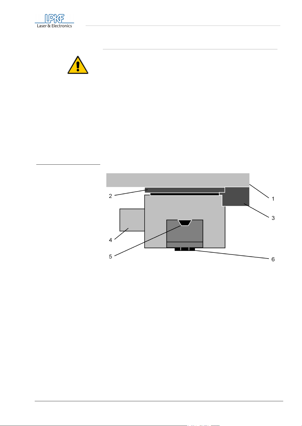
fig. 9: The LPKF ProtoMat M60
working depth limiter
Milling and drilling
7.2 The mechanical working depth limiter
Danger! Keep your fingers away from the movement area of the
machine during operation!
When milling isolation channels in PCB materials, it is extremely
important to keep a constant milling depth. With the LPKF
M60, this done by the mechanical working depth limiter.
This provides the following benefits:
• The depth limiter rides on the surface of the material. The
working depth limiter follows warped PCBs.
• The material is held down within certain limits by the working
depth limiter.
The head is lowered with a solenoid and raised with a spring.
ProtoMat
- Holding plate
1
- Knurled nut used to set milling depth
2
- Holding block for working depth limiter6- Scanning ring in the working depth limiter
3
- Suction nozzle
4
- Tool fixture (collet for manual clamping)
5
Milling depth is set by adjusting the knurled nut (2) on the working depth
limiter. When the wheel is turned clockwise, the milling depth is
increased, while it is reduced when turned counterclockwise. The milling
depth is altered by about 4 µm per step. Turning the knurled knob in
counter-clockwise direction is difficult when the head is lowered.
ProtoMat M60 29
Page 30
Milling and drilling
7.3 Functional elements on the mill/drill head
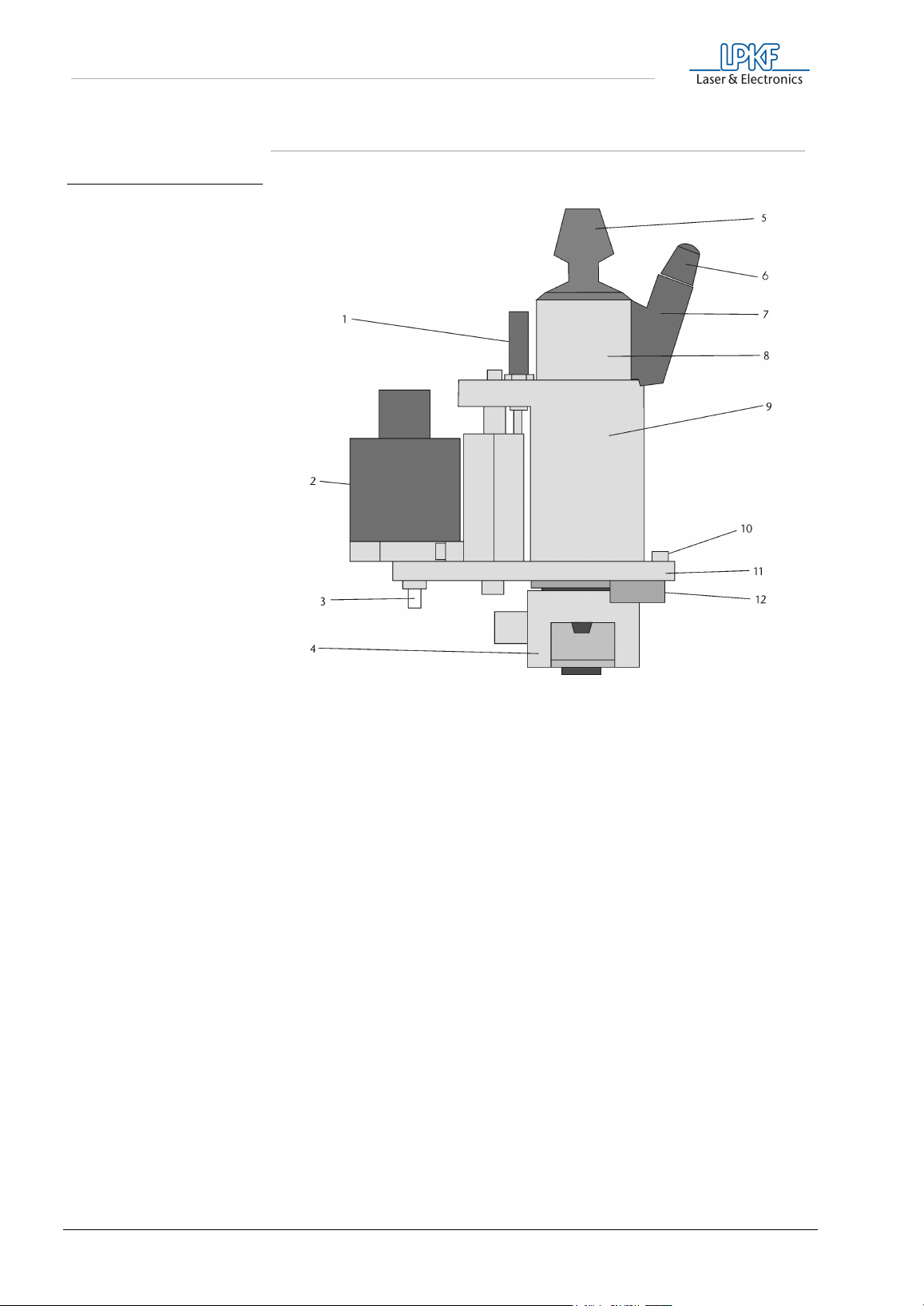
fig. 10: Mill/drill head front view
- Shock absorber
1
- pneumatic cylinder
2
- Adjustment bottom head stop
3
(Attention! Do not move!)
- Working depth limiter
4
- Knob for manual clamping
5
- Connector for high-speedcycle spindle
6
- Socket for high-speedcycle spindle
7
- High-speedcycle spindle
8
- Holding block
9
- Adjustment screw for working depth
10
limiter
- Base plate for high-speedcycle spindle
11
- Setting screw for knurled nut
12
(Attention! Do not move!)
30 ProtoMat M60
Page 31
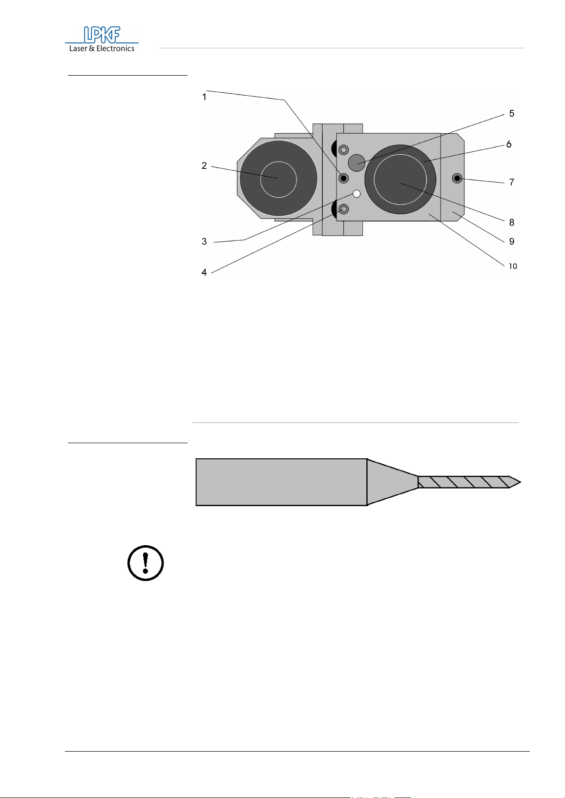
fig. 11: Mill/drill head, view from
above
Milling and drilling
fig. 12: Spiral Drill
- Adjusting nut for head stop, top
1
- pneumatic cylinder
2
- Hole for transport safety devices and options
3
- Axis guide
4
- Shock absorber
5
7.4 Drilling
- High-speedcycle spindle
6
- Fixing screw for working depth limiter
7
- Knob for high-speedcycle spindle
8
- Base plate
9
- Bracket for high-speedcycle spindle
10
Caution! Before drilling make sure that the PCB is positioned
tightly. Switch on the vacuum cleaner!
You must check the PCBs are drilled with special PCB drills. It is
important always to lower the head at a constant speed. This is achieved
by setting the tool as close as possible to the material to be drilled. A
setting nut can be used to make this adjustment. An excessive lowering
speed can result in burrs, particularly where holes have a small
diameter.
Only one PCB can be drilled at a time. It is not possible to stack PCBs
one on top of the other. No drill cover plate is needed. All drills are 38
mm long. For further notes see „Practical tips“ on page 38.
ProtoMat M60 31
Page 32
Milling and drilling
7.5 Isolation milling
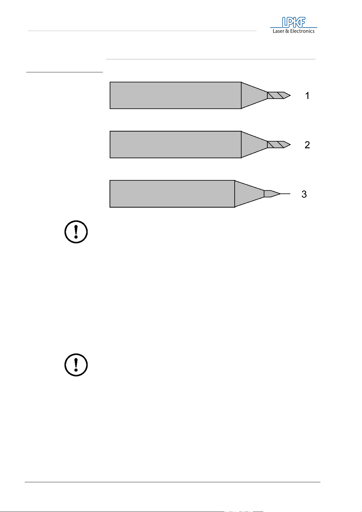
fig. 13: LPKF universal- (1), micro-
(2) and HF-cutter (3)
Caution! Before milling make sure that the PCB is positioned
tightly! Switch on the vacuum system!
Before milling, it must be ensured that sharp LPKF universal milling
cutters (36 mm long) are used. The milling width is set to between 0.2
and 0.5 mm depending on component thickness.
It is advisable to degrease the base material with cleaner spray before
machining (degreaser for electronic components), so that milling dust
can be removed more easily by the extractor.
The milling depth must be set as large (deep) as possible in all cases. If
only the extreme milling cutter tip (<0.2 mm isolation) is used, the tool
wears more quickly than with deeper drilling.
The LPKF micro-cutters can be used to produce even smaller isolation
channels, but their service life is about 10% less than that of the abovementioned universal cutters.
Caution! Do not confuse micro-cutters and universal cutters - both
of them can only be recognize using a microscope.
A cutter has been specially designed for HF-technology. It produces a
rectangular cross section.
32 ProtoMat M60
Page 33
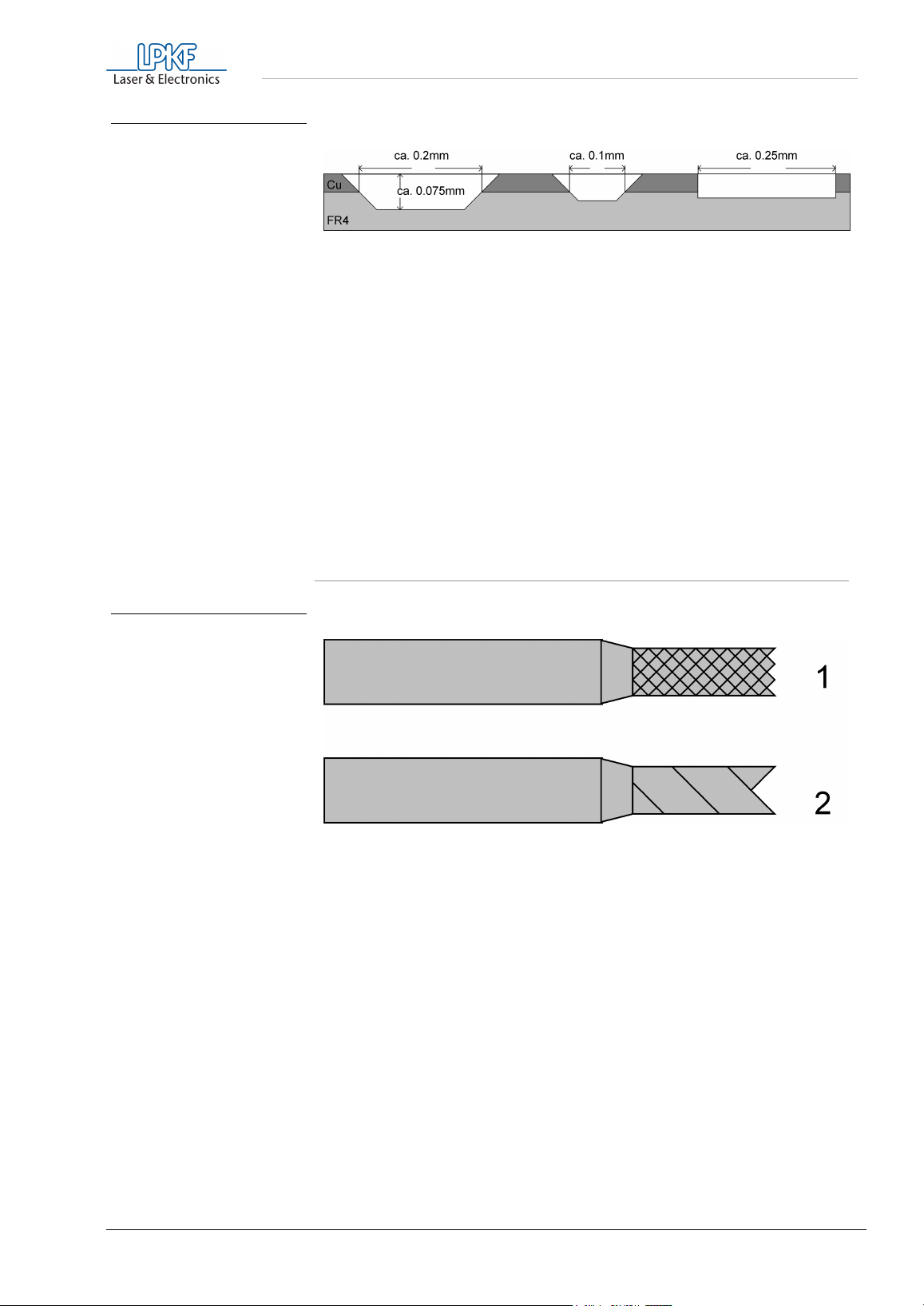
fig. 14: Milling channel of LPKF
universal, micro- and HFcutters
Milling and drilling
For further notes see „Practical tips“ on page 38.
For the advantages and disadvantages of various materials, see the
section „Materials used for machining“ on page 26.
After machining, the PCB has to be cleaned. This can be carried out
either in a brush machine or alternatively manually with board cleaners
(LPKF accessories). In either case, the PCB must be rinsed thoroughly
with water to remove any copper dust produced by brushing.
After rinsing, the PCB must be dried thoroughly (air drier) and then
protected against oxidation by a solder varnish.
fig. 15: Contour cutter (1)
two-edged cutter (2)
7.6 Contour milling in PCB material
The speed of movement has to be lowered for contour milling. This may
differ from material to material. Only use special contour milling cutters
(38 mm long): if possible 1 or 2 mm.
The 1 mm contour milling cutter should only be used for internal holes
(smaller internal radius). Due to the lower stability please set the feed
speed to a minimum.
The 2 mm contour milling cutter is substantially more robust, but does
not remove as much material as the 3 mm milling cutter.
With contour milling using a 3 mm milling cutter, a large quantity of
material is removed. Moreover, the high-speedcycle spindle can be
overloaded if the speed of movement is too high.
For outline milling of soft HF-base material so-called double-edged
cutters are being used instead of the outline cutters.
ProtoMat M60 33
Page 34
Milling and drilling
Caution! All speed ranges and feed rates given in BoardMaster
refer to FR4 material. When other material is used, it is advised to
work with reduced feed rates at first.
Danger! Take into consideration that cancerogenous dusts (due to
glass fibers) might be produced when FR4 material is machined.
Therefore always work with the dust exhaustor switched on.
Always use the superfine filter.
Danger! When machining some materials (e.g. teflon) hazardous
gases might be produced!
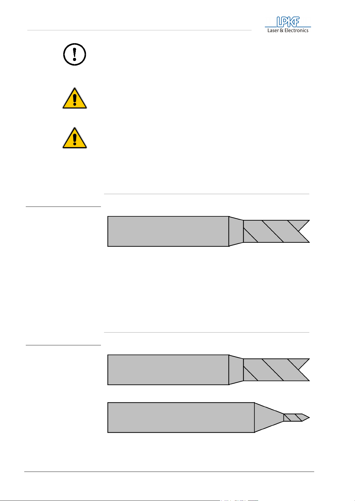
fig. 16: Double chamfered cutter
fig. 17: Universal cutter
7.7 Milling wide isolation channels
Wide isolation channels can be made with a 36 mm long double
chamfered cutter. Various diameters are available.
The milling depth must be set such that when the copper is removed,
only minimal burring results. The 3 mm double chamfered cutter is
particularly well suited for milling very wide isolation channels (VDE
regulations).
7.8 Front plate engraving
34 ProtoMat M60
Page 35
Milling and drilling
For engraving, set the speed of movement as appropriate for the
engraving depth and the material. Use an LPKF universal milling cutter
or LPKF double chamfered cutter.
Danger! Use extractor when engraving, too!
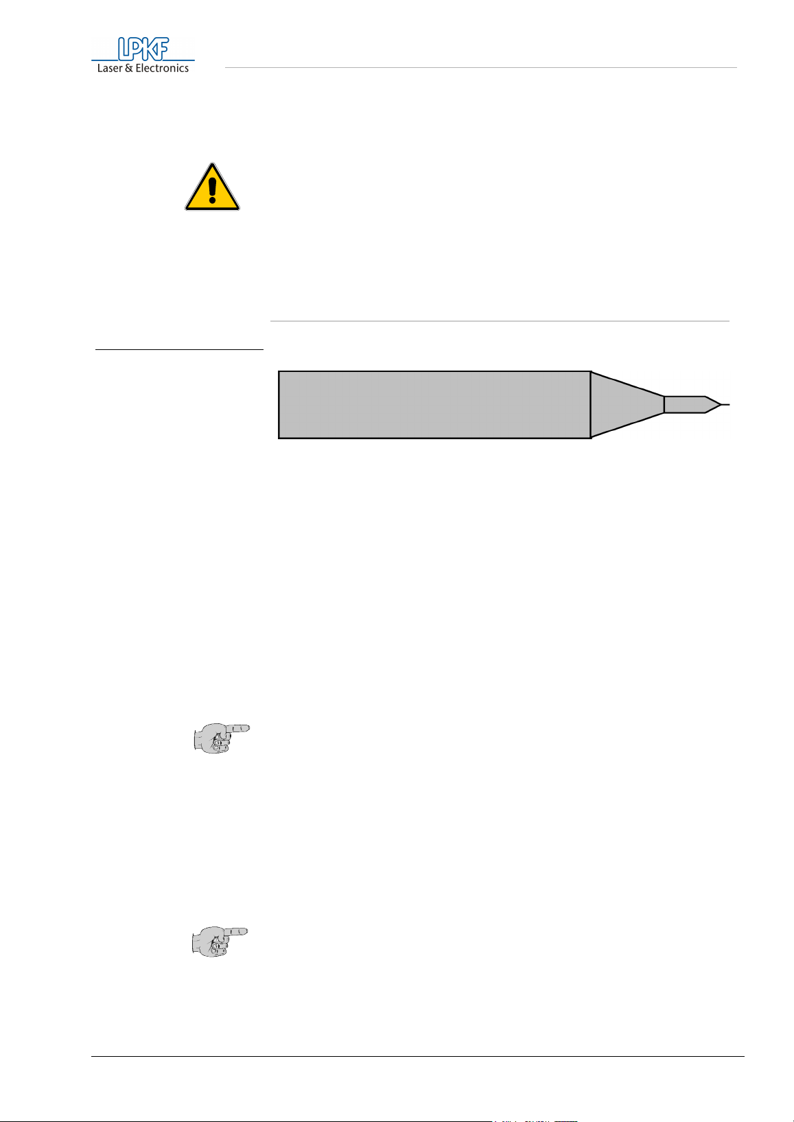
fig. 18: HF-Cutter
The LPKF
ProtoMat
can be used for milling through 3 mm thick
aluminium front panels.
7.9 Milling layout films
› Secure the film base (sheet of perspex or glass) on the machine
table with masking tape.
› Lay the film material on the base with the coated (matte) side facing
upwards.
› Now smooth the film material firmly and level on the film support until
the air has been completely expelled.
› Now stick down the film on all four sides with transparent adhesive
tape (which must not stretch) to form an air seal. There must not be
any air bubbles between the film and the base.
The milling depth can now be set at the film edge. It can be checked
by milling a frame around the film area (manual movement).
› The speed of movement should be reduced to about 15 mm/sec.
Note: The HF-cutter 0,25 mm is used for the milling of layout films.
› Switch on extractor, but only to half power, by extracting "secondary
air" on the suction nozzle or, if there is one, reducing the power on
the electronic extractor control.
The film milling program can now be started.
Film material comes in DIN A3 and A4 formats (special sizes available
upon request).
Note: The film coating is easily scratched and is water soluble, so
do not let it come into contact with water. The film can be recopied
with a coloring device upon request. For further notes see chapter
„Practical tips“ on page 38.
ProtoMat M60 35
Page 36

Milling and drilling
7.9.1 Correction agents
Gravure films can be corrected with Duroscal correction liquid red, which
is easy to use. Paint in the problem areas with it, leave to dry for about 5
minutes and then further process the gravure film in the normal way.
The corrected areas can only have their coating removed with a quick
acting coating remover.
Caution! Follow the safety instructions on the correction agent
container!
7.9.2 Coloring milled films
For milled negative films, there is Duroscal color black, with which
positives can be made. The fully milled gravure film is colored with
Duroscal color by pouring the liquid onto a SAFIR pad and spreading it
evenly over the whole film. Excess color must be wiped off with cellulose
wadding. The stained film must be held against the light to check it and
to find poorly covered areas so that they can be re-colored. Then
immediately remove the coating. The color must not dry.
Caution! Follow the instructions on the color container! Important:
the liquid must not get onto the back of the film as it cannot then be
removed from it. The color is also difficult to remove from other
surfaces (fabrics, skin) (wear apron and rubber gloves)!
7.9.3 Coating removal
Caution! Follow the safety instructions on the quick-acting coating
remover container!
When removing coatings, only treat one film per container to prevent any
damage of the second film by contact between the back of it and a
surface wet with color.
There are two options when it comes to coating removal:
Quick coating removal
Pour the quick-acting coating remover onto the film and immediately
wipe the dissolved protective coating with cellulose applying slight
pressure. Then dry the film with cellulose wadding, blotting paper or a
cloth.
Removal with water
For this method, the film must be placed in a bowl of hand-hot water (to
which a small amount of washing-up liquid has been added). The
protective layer dissolves after about 30 minutes. Any coating remains
must be removed with a fine hand brush. This method is cheaper and
more environmentally friendly. The film can be left in the water bath as
long as you want.
36 ProtoMat M60
Page 37

Milling and drilling
7.10 Milling of solder mask foils
Settings
Tool: Unimill 100 micro cutter
Tool diameter: 0,15 mm
Totational speed: 40.000 (20.000) min-1
Speed: 10 (5) mm/s
Values in brackets apply to circuit board plotters with DC-motors!
› Adjust the milling depth on the unused edge of the solder mask foil.
› To adjust the milling depth, cut a square of 2 x 2 mm with the engine
switched on using the processing keys of
› Switch on the exhaust unit.
BoardMaster
.
› Start the milling with the data prepared by
› After the milling process, check if all pads have been cut out. If not,
start the milling process again.
CircuitCAM
7.11 Drilling with the micrometer screw
The micrometer screw is used for the exact depth adjustment regardless
of the material surface. It enables the processing of packed boards as
well as mechanical parts. The lower oin of the micrometer screw serves
as a stop and prevents the further lowering of the machine head.
.
7.12 Cleaning the PCB
Before components are mounted, the finished PCB must be thoroughly
cleaned. This can be carried out manually or in PCB brushing machines.
If cleaning by hand, the PCB is placed on a flat support. The board is
brushed in the direction of the conductor paths with wet board cleaner
(e.g. LPKF board cleaner PAD). The purpose of the brushing is on the
one hand to remove the layer of oxidation and on the other to remove
swarf in the isolation channels. After brushing, the PCB must be free of
any metal particles. From now on, the board should only be held by its
edges and with gloves. The board should now be rinsed under running
water and then dried with an air drier.
Caution! Never use compressed air as the oil particles it contains
can cause problems later on.
After drying, both sides of the board are coated with solderable lacquer.
ProtoMat M60 37
Page 38

Milling and drilling
7.13 Practical tips
• Set the milling depth such that
engraving is too deep
rather
than too shallow. Insufficient depth when engraving promotes
milling tool wear.
• There can be a number of causes of
(depth)
.
• It is important that the
•
Residues of adhesive tape
machine bed is clean
uneven milling width
.
or such like can adversely
affect milling depth quite considerably.
• Also,
milling swarf
between the machine bed, drilling
support and PCB can reduce precision.
• Greatly
distorted materials
bend such that the sag shows
underneath; in this case, secure the edges well with adhesive
tape.
• Another important point for precise milling depth is the
removal
of milling and drilling chips.
•
Hooks
can occur
between the milling channels
if the incorrect
milling direction sequence was specified followed, in particular
with circles. If a circle is to be milled with a tool which rotates
clockwise,
fine hooks
can arise between the copper areas if the
milling tracks should overlap. The reason for this is that the
cutting speed on the outer edges is reduced.
The solution lies in selecting the right milling direction. When
isolating conductor paths with LPKF isolate, the solder side
should be mirrored before isolating as the isolation algorithm
itself works in a clockwise direction. The standard postprocessing
is already designed for this.
CircuitCAM
allows the user to select
the direction of the milling tool and therefor mirroring prior to
isolation is not necessary.
•
Milling burrs
can be caused by blunt tools or incorrect speeds of
movement. If possible with the structure to be milled, deeper
settings can be the answer. Otherwise, change the tool.
•
Burrs when contour milling
or
cut edges which are not clean
occur either due to a blunt tool or incorrect advance speed.
• With some materials, the
color of the milled channel
gives
some indication of the state of the tool. With epoxy materials,
dark isolation paths indicate a sharp tool, while lighter ones
indicate a blunter tool.
•
Drilling burrs
occur either because the tool is blunt or the head
lowering speed is excessive. In the first case, change the tool. In
the second case, the tool height over the material must be
reduced.
•
Drill deflection
occurs in particular with thin tools which are no
longer absolutely sharp. However, this also depends on the
surface structure of the material. If, for example the glass fiber
structure of FR4 materials penetrates the copper, drill deflection
cannot be avoided even with a sharp tool. For materials with
additional, removable copper film (FR4 material with 18 µm or 9
µm Cu coating), drill deflection is very slight. With an additional
processing step all drillings can first be marked. This also avoids
the deviation of the drill.
38 ProtoMat M60
Page 39

Milling and drilling
•
Vitrification of the drilled hole
occurs where the drill stays in
the hole too long once the hole has been made. These holes
then cause problems at feedthrough stage. Reduce drilling times
as appropriate.
•
Drills break
where the drilling base has already been used a
number of times. The drilling base should be changed for every
new PCB. It is not really possible to prevent breakage if a drill
comes into contact with the edge of an existing hole in the base.
Broken tools must be removed from the PCB and the drilling
base. Drills can also break if the tool is too high above the
material. By moving the adjustment valves of the pneumatic
stroke the lowering speed can be adjusted. This prevents the
breaking of drills and increases the edge life of all tools.
• In film milling,
milled channels are uneven
under the film. If the
is secured with
film
if there is still air
elastic adhesive tape
waves may form in the film after a while. It is particularly
important here that the milling base should be level (LPKF film
engraving base).
•
are produced when milling films either because the tool is
Burrs
blunt or milling was too deep.
•
Misalignment of the solder and component sides
occurs
where the HOME position is not accurately programmed.
,
ProtoMat M60 39
Page 40
Appendix
8.0 Appendix
8.1 Maintenance
• Keep spindles clean.
• In rooms with a high air humidity, wipe down with a lightly oiled
cloth from time to time.
• Keep transport spindles oiled and clean.
Caution! Do not oil bearings!
Please use LPKF plastic lubrication.
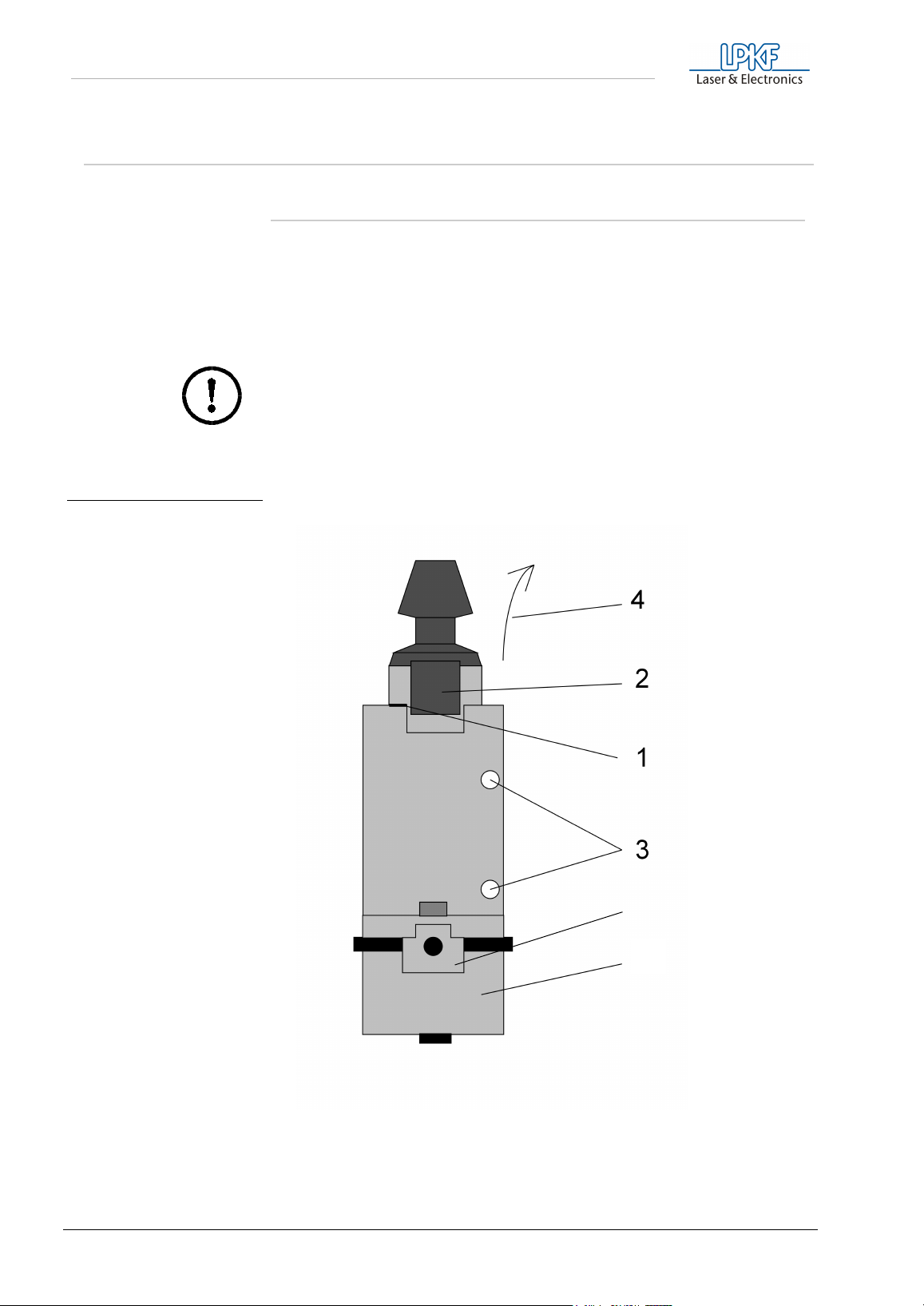
fig. 19:
5
6
40 ProtoMat M60
Page 41

Appendix
Strip and clean working depth limiters at regular intervals. To do this, first
switch the device off, then proceed as follows:
› Mark the insertion depth of the spindle (1).
› Remove connector from the spindle (2).
› Release Allen screw with which the high-speedcycle spindle is
clamped to the holding block (3).
› Spindle can now be pulled out towards the top (4). If necessary, turn
it slightly to the left or to the right.
› Remove the holding block.
› The working depth limiter (6) can now be removed toward the side
for cleaning .
› Clean both parts of the working depth limiter using the brush
provided.
Caution! Only lightly lubricate the thread of the working depth
limiter with graphite or Teflon!
› After cleaning the working depth limiter is refitted following the
procedure in reverse. The spindle is inserted into the holding block.
Observe the insertion mark!
› Check the correct insertion depth of the spindle before setting it into
operation. The distance between the drill tip and the machine plate
must be 0.5 mm when the head is in its lower position.
Caution! The machine plate can be damaged during drilling when
this distance is too small. At an insufficient distance the device can
no longer drill through the workpiece.
› At last tighten the screws again (3) and put the connector again on
the spindle.
Check the distance when mounting the high-speedcycle spindle
ProtoMat M60 41
Page 42
Appendix
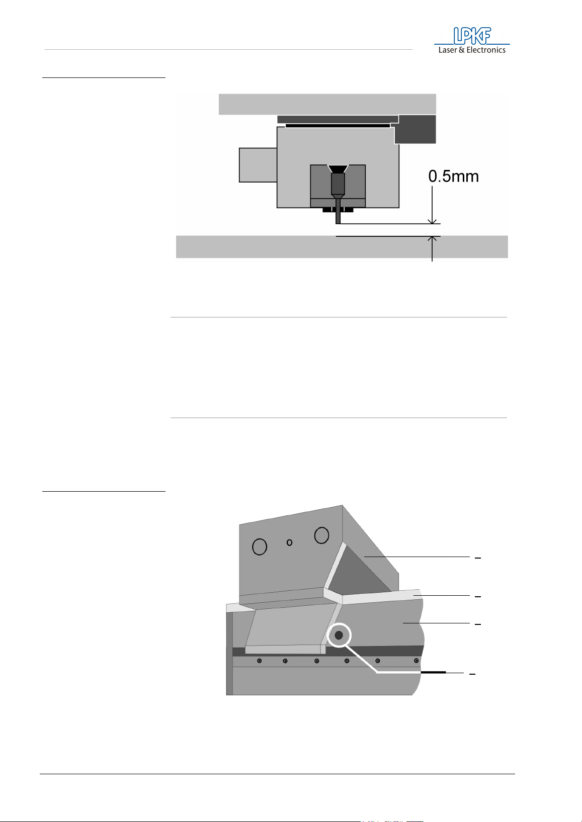
fig. 20:
8.2 Lubricating the carriage guide wipers
fig. 21:
You must make sure that the carriage guide wipers on the LPKF
ProtoMat
M60 are always well lubricated.
8.2.1 Carriage guide wipers of the X-axis
The wipers (4 in total) are located on both sides of the carriage both in
front of and behind the guide cheeks. A hole has been drilled on the left
and right of the guide rail cover to allow access these wipers.
1
2
3
4
- Tool carriage
1
- Machine base plate
2
- Cover for guide rails
3
- Supply port
4
42 ProtoMat M60
Page 43

Appendix
8.2.2 Oiling the rear wipers
› Move the carriage to the tool change position.
The supply ports are now behind the guide wall.
Use the syringe to inject oil through the port and into the hole on both
sides of the wiper (0,5 ml).
8.2.3 Oiling the front wipers
› Move the carriage 112 mm to the rear (+X) of the tool change
position.
The supply ports is now located in front of the guide wall and the
wipers can be oiled using the syringe.
Caution! Wipe any excess oil from the casing as it might corrode
the paintwork. Never move the carriage manually. Doing so could
cause the output stages of the stepping motors to be damaged by
induced voltage.
8.3 Serial port SERIAL 1
The serial data channel SERIAL 1 is an RS 232-C standard interface
with photo diode decoupling and is used for communication between the
control unit and a PC. The DCD signal input on the control means that
the control unit can be STOPPED quickly when the signal level changes
from low to high. In this way, it is possible to stop the machine directly
from the PC by activating the DTR signal. The SERIAL 1 transmission
speed is programmed with DIL switches 1 and 2.
Switch 1 Switch 2 Baud rate
OFF OFF 4800 baud
ON OFF 9600 baud
OFF ON 19200 baud
ON ON -
SERIAL 1 settings:
Pin Signal Meaning
2 TXD Transmit data
3 RXD Receive data
4 RTS Request to send
5 CTS Clear to send
ProtoMat M60 43
Page 44

Appendix
7 GND-I Ground (isolated)
8 DCD Data carrier detect
20 DTR Data terminal ready
All signals are electrically galvanically decoupled; all contacts not
mentioned are not used.
8.4 Serial port SERIAL 2
The serial data channel SERIAL 2 is an RS 232-C standard interface
and can be used for communication between the control unit and
another system. The transmission speed of SERIAL 2 is programmed
with DIL switches 3 and 4.
Switch 3 Switch 4 Baud-rate
OFF OFF 4600 baud
ON OFF 9600 baud
OFF ON 19200 baud
ON ON -
SERIAL 2 settings:
PIN Signal Meaning
3 TXD Transmit data
2 RXD Receive data
7 RTS Request to send
8 CTS Clear to send
5 GND Ground
All contacts not mentioned are not used.
8.5 Motor connection
The stepping motors are connected per axis via a 15-pole SUB-D plug. If
the limit switch is actuated, any further axis movement in the direction of
the limit switch is immediately blocked. The position of the sockets is
described in the section see „Displays and connections“ on page 15.
Another 5-pole cable is used to supply the high-speedcycle spindle with
power.
Caution! Never confuse the stepper motor and the mill/drill head
cables!
44 ProtoMat M60
Page 45
Appendix
8.6 Mill head connection
The mill/drill head is connected to the control unit with a 15-pole socket.
The socket position is described in the section see „Displays and
connections“ on page 15. Another five-pole cable supplies the highspeed cycle spindles.
Caution! Never confuse the stepper motor and the mill/drill head
cables!
8.7 EPROMs
The software for the control unit is in 2 EPROMs. If the EPROMs need to
be replaced (updates), the LPKF
dismantled, so follow the procedure described in the section „Fuses,
commuting the device voltage“ on page 45 and change the EPROMs,
ensuring that the EPROMs are correctly aligned and positioned.
ProtoMat
M60 has to be partially
Use only an IC extractor to remove the EPROMs as otherwise the
contacts of the mounting might be damaged. When inserting new
EPROMs support the PCB from the bottom in order to avoid bending of
the board. Take care that the orientation of the EPROMs is correct.
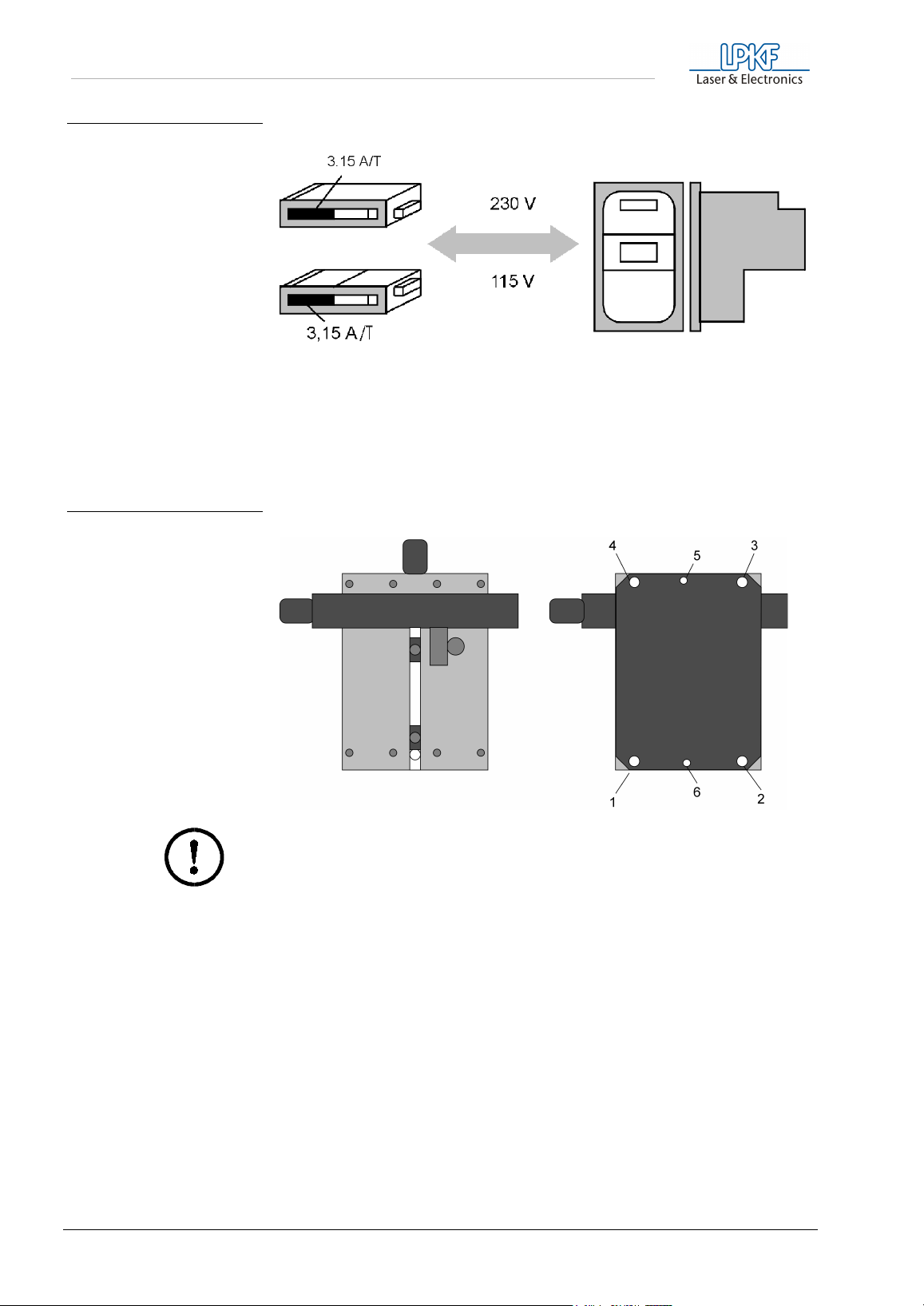
8.8 Fuses, commuting the device voltage
Danger! Before working on the fuses or opening the device, make
sure that the power cord is removed!
In the LPKF
fused. The main fuses (primary) are in the power connection of the
control unit and are accessible from the outside.
Caution! When switching to another line voltage make sure that
both fuses are exchanged. Both fuses must be of the same value.
ProtoMat
M60, the primary and secondary voltages are
ProtoMat M60 45
Page 46
Appendix
fig. 22: Voltage setting and fuses
The secondary fuses are inside the control unit. The control unit must
first be removed from the mechanical part to replace the fuses. To do
this, loosen screws 1, 2, 3 and 4 at the bottom of the device and then
remove the cable connections between the mechanical part and the
control unit.
fig. 23:Position of screws for
removing the electronics
from the mechanical part of
an LPKF ProtoMat M60
Caution! Be sure the power cable is removed!
› Remove the cover with the x limit switches.
The control unit thus released is constructed as Fig. 24 on page 47.
46 ProtoMat M60
Page 47
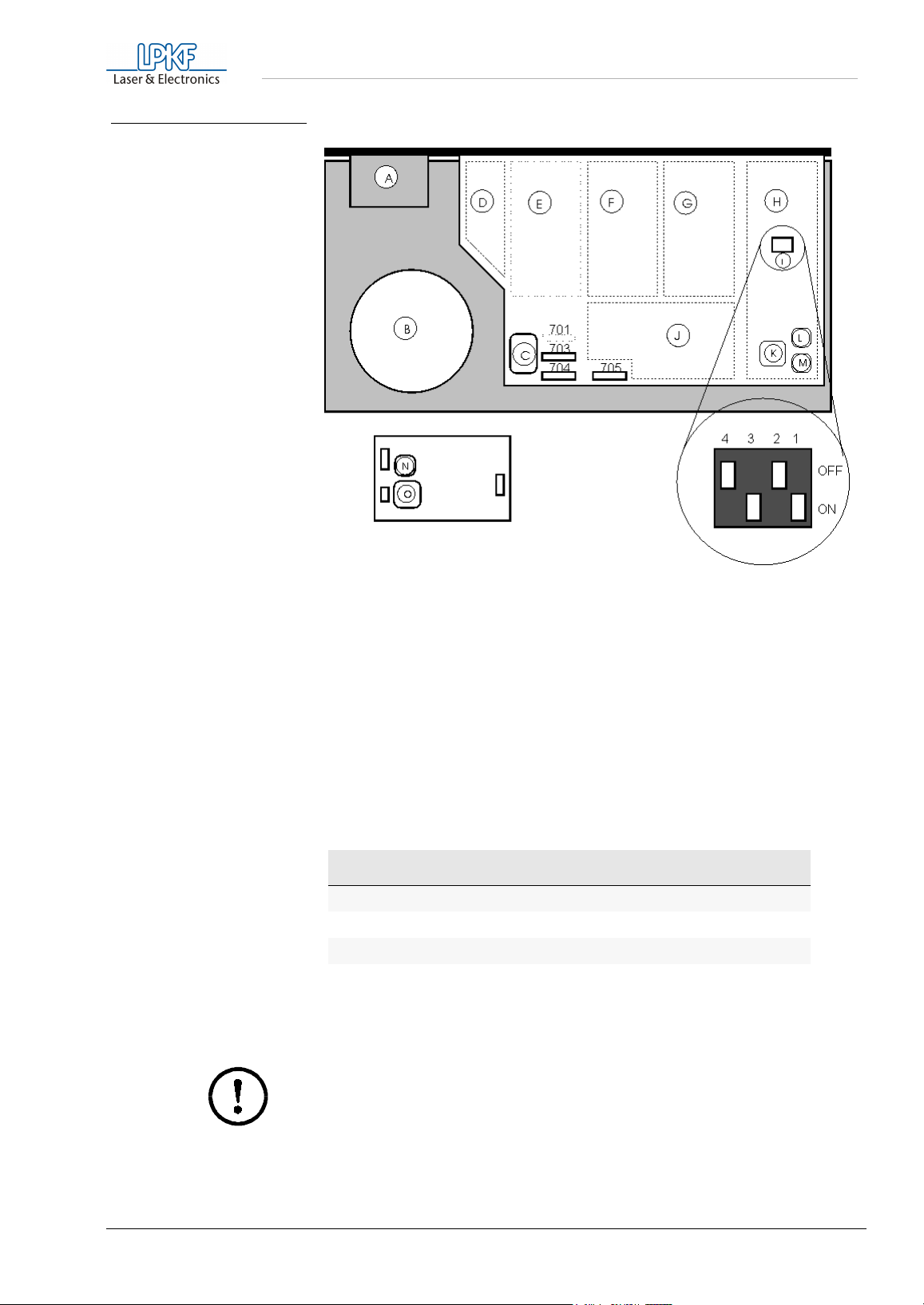
fig. 24: View of the PCB of the LPKF
ProtoMat M60 PCB
Appendix
- Power filter
A
- Transformer
B
- Transformer connection
C
- Power pack for mill/drill head L- EPROM L
D
- Power pack, Z axis (not used)M- EPROM H
E
- Power pack, Y axis
F
- Power pack, X axis
G
- Processor section
H
- DIL switches for baud rate setting (with default setting)
I
- Power packs
J
- Processor
K
- EPROM of the high-speedcycle spindle
N
(PCB under cover)
- Processor of the high-speedcycle spindles
O
(PCB under cover)
= Various fuses (see below)
701-705
The secondary current circuits are protected with fine-wire fuses as
follows:
Fuse Type Power circuit
F701 3,15 A M Power high level
F703 3,15 A M voltage for milling spindle, 24V
F704 2,00 A M +5V and VREF
F705 0,50 A M RS 232 C / SER1
The units are mounted in the opposite sequence to that described above
for dismantling.
Caution! Never confuse the stepper motor and the mill/drill head
cables!
ProtoMat M60 47
Page 48

Appendix
Before switching on, always check that the head and motor cables are in
the correct place.
The fuses in the primary current circuit are in the power switch, which
also contains the mains filter and the power selector (e.g. 230 V/115 V).
The fuses should be medium semi-time lag:
• 230V fused with 3.15A/T
• 115V fused with 3.15A/T
8.9 The LPKF ProtoMat M60 Commands
8.9.1 Command structure
The SMCU (Signal Processor Control Unit) control unit of the machine
interprets the HP-GL commands described below and converts them
into set reactions.
The resolution of the machine is 0.0079375mm. This is a different
resolution than that of standard HP-GL-plotters. Therefore the output is
scaled down when original commands are used.
The syntax:
Symbol
{...}
()
[]
Meaning
The contents can be repeated any number of times
The command parameters are between these brackets.
The content of these brackets is optional and does not
have to be included.
The SMCU expects a separator between the command parameters
which is not any of the figures or upper case letterscapitals. A new
command can follow a parameter without a separator. The last character
in a command file which is sent must be a semicolon or a line feed
symbol (0A hex.).
Unknown commands are ignored by the control unit, but their
parameters can lead to unwanted plot absolute or plot relative
commands.
48 ProtoMat M60
Page 49

Appendix
8.9.2 HP-GL standard commands
AA (x,y,a{,?}){;}
Arc Absolute
Draws an arc around the absolute coordinate (x,y) starting from the
current position with the arc angle a=[degree]. With a negative arc angle
a, it is drawn clockwise, but otherwise counterclockwise.
AR(x,y,a{,?}){;}
Arc Relative
Draws an arc around the relative coordinate (x,y) starting from the
current position with the arc angle a=[degree]. With a negative arc angle
a, it is drawn clockwise, but otherwise counterclockwise.
CI (r{,?}){;}
Circle
Draws a complete circle around the current position with radius r.
Resolution ß is ignored as the maximum resolution is always used when
drawing.
EA (x,y){;}
Edge rectangle absolute
Draws a rectangle defined by two corner points lying diagonally to each
other. The first corner point is determined by the current position and the
second by the absolute coordinate (x,y).
ER (x,y){;}
Edge rectangle relative
Draws a rectangle defined by two corner points lying diagonally to each
other. The first corner point is determined by the current position and the
second by the relative coordinate (x,y).
IN {;}
Initialize
Changes the control unit to the same status as after switching on. This
restores all default settings.
IW (x0,y0,x1,y1){;}
Input window
Restricts the working area on the XY axis to a window with the given
corner coordinates.
OH {;}
Output hard clip limits
The control unit automatically determines its maximum travel range
within the limit switches and send the coordinates determined in this way
as an ASCII string in the form ("W
Xmin,Ymin,Zmin,Xmax,Ymax,Zmax<cr>") to the PC.
OS {;}
Output status
The control unit sends its status line as ASCII hex ("S xxxx <cr>") to the
PC.
PA (x1,y1{,...xn,yn}){;}
Plot absolute
Draws a line from the current position to the absolute coordinates listed
one after the other. The commands PU and PD can be given between
the pairs of coordinates as parameters. If additional pairs of coordinates
are sent, the command word PA is not necessary. All pairs of
coordinates without a command word are taken to relate to the last PA or
PR commands sent and are carried out accordingly.
ProtoMat M60 49
Page 50

Appendix
PD {;}
Pen down
Lowers the tool.
PR (x1,y1{,...xn,yn}){;}
Plot relative
Draws a line from the current position to the relative coordinates listed
one after the other. The commands PU and PD can be given between
the pairs of coordinates as parameters. If additional pairs of coordinates
are sent, the command word PA is not necessary. All pairs of
coordinates without a command word are taken to relate to the last PA or
PR commands sent and are carried out accordingly.
PU {;}
Pen up
Lifts the tool.
VS (v{,n}){;}
Velocity select
Defines the track speed in the XY level v=[µm/s] with the tool lowered
and allocates this speed to the tool with number n.
8.9.3 Special commands
All special commands begin with the symbol "!" and their syntax is
otherwise like that for HP-GL standard commands.
!AS (a){;}
Acceleration Set
Defines a new acceleration constant a=mm/s
10...50000.
!CC {;}
Close channel
Ends a data transmission introduced with !OC.
!CM (n){;}
Change mode
Switches between the drill (n=0) and mill (n=1) working modes.
!CT (n){;}
Command counter
Switches between echo mode (n=1) and non-echo mode (n=0). In echo
mode, the machine acknowledges every correctly completed command
with the message "C<cr>".
!EM (n){;}
External motor
Switches the mill/drill motor on (n=1) or off (n=0).
²
. The valid value range is
!ES (n){;}
Enable stop
Release (n=1) and block (n=0) the external stop function. After switching
on, the external stop function is blocked.
!FP {;}
Full power
Switches the motors of the XYZ axis to full power.
50 ProtoMat M60
Page 51

Appendix
!HP {;}
Half power
Switches the motors of the XYZ axis to half power.
!OC {;}
Open channel
Opens a direct data transmission from serial data channel SER1 to
serial data channel SER2. All characters received on data channel
SER1 are sent to data channel SER2 until the character string !CC is
received.
!ON (a){;}
Output nominal position
The control unit sends the nominal position (target position) of the motor
axis addressed with parameter a. The following addresses are attributed
to the motor axes:
• 0 = X,Y,Z axis
• 1 = X axis
• 2 = Y axis
• 3 = Z axis
!RD (a){;}
Read port
Effects the reading of the input port with the address a=<0..15>. The
data is output via the serial interface from the which the command came,
as an ASCII figure.
!RS (r){;}
Resolution set
Gives the control unit the step size (r=µm/step) of the machine. The valid
value range is 1...32000.
!TA (x,y,z){;}
Plot three-D absolute
Carries out a physical movement from the current position to the
absolute coordinate (x,y,z).
!TD (t1,t2,t3,t4){;}
Time for drilling
Sets new drill times t=[ms].
!TM (t1,t2,t3,t4){;}
Time for milling
Sets new mill times t=[ms].
!TR (x,y,z){;}
Plot three-D relative
Carries out a physical movement from the current position to the relative
coordinate (x,y,z).
!TS (t){;}
Time to stabilize
Sets a stabilization time t=[ms] between the individual commands.
!TW (t){;}
Time to wait
The following command is only carried out after a wait t=[ms].
ProtoMat M60 51
Page 52

Appendix
!VU (v){;}
Velocity if pen up
Defines the track speed v=[µm/s] of the movement in XY plane when the
tool is raised.
!VZ (v){;}
Velocity Z axis
Defines the speed v=[µm/s] of the movement in the Z axis.
!WR (a,d{,m}){;}
Write port
Effects an output of the data word d on the port address a=<0..15>,
whereby a bit mask can be given.
!ZA (z){;}
Plot Z axis absolute
Moves the Z axis from the current position to the absolute coordinate (z).
!ZR (z){;}
Plot Z axis relative
Moves the Z axis from the current position to the relative coordinate (z).
8.9.4 Special command for the high-speedcycle spindle
Before communicating with the high-speedcycle spindle, send the
command for opening the SERIAL2 (!OC;), then the serial interface
SERIAL2" must be closed again (!CC;)
!RM (r){;}
Revolutions Motor, r=0...60.
Sets the speed (r)*1000 of the high-speedcycle spindle.
8.9.5 Direct commands
Direct commands are special commands which, once they have been
interpreted, are carried out via the command buffer.
!CB{;}
Clear buffer
Deletes all commands from the command buffer.
!GO{;}
Go on
Removes the stop command and continues the command
implementation.
!RC{;}
Repeat command
Repeats the last command carried out.
!ST{;}
Stop
Interrupts command processing when the current command is
completed.
52 ProtoMat M60
Page 53
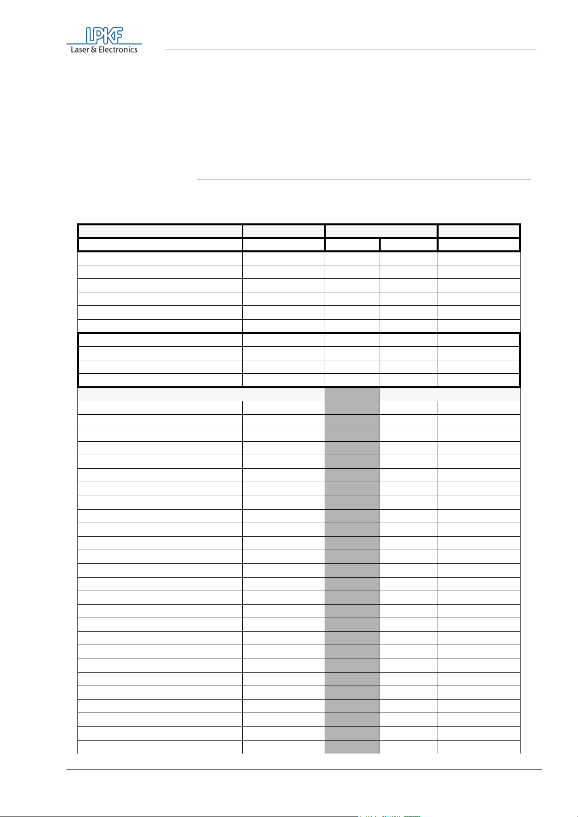
Appendix
The command set implemented is a subset of the HP-GL. If the
equipment is to be driven by any CAD system, with HP-GL commands, it
must be ensured that the step size is substantially lower than with
normal pen plotters.
The step size is 7.9375 µm/step (0.0003125 inch/step).
8.10 Inventory of available tools
Tools shaded gray cannot be used for the LPKF
Name Diameter. Length Delivery
in mm 36 mm 38 mm L= in stock
Universal milling cutter 0.2 - 0.4 * L
micro milling cutter 0.1 -0.2 * L
HF-Cutter 0.25 * L
Konturenfräser 1.0 * * L
2.0 * * L
3.0 * * L
Double chamfered cutters 0.8 * L
1.0 * * L
2.0 * * L
3.0 * L
Drills 0.5 * L
0.55
0.6
0.65
0.7
0.75
0.8
0.85
0.9
0.95
1.0
1.05
1.1
1.15
1.2
1.25
1.3
1.35
1.4
1.45
1.5
1.55
1.6
1.65
1.7
1.75
1.8
** L
**
** L
** L
** L
**
** L
** L
** L
**
** L
** L
** L
**
** L
**
** L
**
** L
**
** L
**
** L
ProtoMat
*
*L
*
M60.
ProtoMat M60 53
Page 54

Appendix
1.85 **
1.9
1.95
2.0
2.05
2.1
2.15
2.2
2.25
2.3
2.35
2.4
2.45
2.5
2.55
2.6
2.65
2.7
2.75
2.8
2.85
2.9
2.95
3.0
3.05
** L
**
** L
**
** L
**
** L
**
** L
**
** L
** L
** L
**
** L
**
** L
**
** L
**
** L
**
** L
**
8.11 Concluding remarks
As a rule the machine recommendations 93 / 44 of the European
Community, dated June 14, 1993 applies to this manual. If an EC
recommendation has not been taken into consideration in one of the
chapters, these recommendations are hereby referred to and any claims
concerning completeness and liability are excluded. Furthermore, we
hereby point out to remaining risks unknown to the manufacturer which
might occur due to inexpert handling of the machine. LPKF is not
responsible for damage following the operation and handling of the
LPKF
ProtoMat
having been referred to.
M60. This also applies to the case of these damage
54 ProtoMat M60
Page 55

8.12 Declaration of conformity
Appendix
1. Manufacturer of the machine designated LPKF
ProtoMat
M60 is
company:
LPKF
Laser & Electronics AG
Osteriede 7
D-30827 Garbsen
Germany
2. The machine designated as LPKF
ProtoMat
M60 is a circuit board
plotter, suitable for the production of circuit boards-prototypes and
engraving films, as well as for the engraving of aluminum or plastics.
The series number of the above-mentioned machine is
1P....................... (see also bottom plate). Further details of the LPKF
ProtoMat
3. The LPKF
M60 can be seen in the enclosed manual.
ProtoMat
M60 corresponds to the provisions of the EC
recommendation 93/44 dated June 14,1993 ( see also Appendix I of
the recommendation).
4. Existing DIN regulations have also been applied for the production of
the LPKF
ProtoMat
M60.
5 Authorized signatory is
Mr. Bernd Hackmann
Technical Manager LPKF
Osteriede 7
D-30827 Garbsen/Germany
Bernd Hackmann
ProtoMat M60 55
Page 56

Appendix
8.13 Konformitätserklärung
1. Hersteller der mit LPKF
ProtoMat M60
bezeichneten Maschine ist die
Firma:
LPKF
Laser & Electronics AG
Osteriede 7
D-30827 Garbsen
2. Bei der mit LPKF
ProtoMat M60
bezeichneten Maschine handelt es
sich um einen Fräsbohrplotter, der zum Erstellen von
Leiterplattenprototypen und Gravurfilmen, sowie zum Gravieren von
Aluminium oder Kunststoff geeignet ist. Die Seriennummer der
vorstehenden Maschine ist 1P............(siehe auch Bodenplatte).
Weitere Angaben zur LPKF
ProtoMat M60
sind dem beiliegenden
Handbuch zu entnehmen.
3. Die LPKF
ProtoMat M60
entspricht den Bestimmungen der EGMaschinenrichtlinie 93 / 44 vom 14. Juni 93 (siehe auch Anhang I der
Richtlinie).
4. Bei der Erstellung der LPKF
ProtoMat M60
fanden auch bestehende
DIN- Vorschriften Anwendung.
5. Bevollmächtigter Unterzeichner dieser Erklärung ist
Herr Bernd Hackmann
Vorstand LPKF AG
Osteriede 7
D-30827 Garbsen
Bernd Hackmann
56 ProtoMat M60
Page 57

9.0 Index
Index
A
accessories
alignment holes
aluminum
available tools
..................................................................................................................... 11
............................................................................................................ 21
......................................................................................................................... 10
................................................................................................................ 53
B
Burrs
................................................................................................................................... 39
C
Caution
changing a tool
Characteristics
Commands
Connections
Conventions
................................................................................................................................4
............................................................................................................. 18
.............................................................................................................. 10
..................................................................................................................... 48
................................................................................................................... 13
..................................................................................................................... 4
D
Danger
Drilling performance
Drills break
Duroscal
................................................................................................................................4
...................................................................................................................... 39
........................................................................................................................... 36
................................................................................................... 10
E
engraving
Engraving film
EPROM
extractor
......................................................................................................................... 10
................................................................................................................ 27
............................................................................................................................. 45
........................................................................................................................... 26
F
fiber reinforced epoxy
FR 3
.................................................................................................................................... 26
FR 4
.................................................................................................................................... 26
Fuses
................................................................................................................................. 45
............................................................................................... 26
G
gravure films
guarantee
................................................................................................................... 10
........................................................................................................................ 10
H
HF and microwave applications
high-speedcycle spindle
HOME position
Humidity
.............................................................................................................. 20
........................................................................................................................... 10
.......................................................................................... 17
........................................................................... 27
ProtoMat M60 57
Page 58

Index
L
Lubricating
.......................................................................................................................42
M
machine positions
materials
...........................................................................................................................26
micrometer screw
Mill head connection
mill/drill head
Motor connection
........................................................................................................14
.........................................................................................................37
...................................................................................................45
...................................................................................................................30
..........................................................................................................44
N
negative films
new two-pin system
Note
.......................................................................................................................................4
.................................................................................................................36
....................................................................................................22
O
Oiling
Orientation
...................................................................................................................................43
...................................................................................................................4, 14
P
Power consumption
....................................................................................................10
Q
Quick coating removal
...............................................................................................36
S
Securing the PCB
serial interface
Serial port
sound
symbols
...................................................................................................................43, 44
.................................................................................................................................. 11
...............................................................................................................................4
........................................................................................................28
...............................................................................................................19
T
Te fl o n
Temperature
tips
tools
transport safety
two-pin system
..................................................................................................................................26
....................................................................................................................10
.......................................................................................................................................38
.....................................................................................................................................25
.............................................................................................................12
..............................................................................................................20
V
Vitrification of the drilled hole
Voltage
...............................................................................................................................10
.................................................................................39
W
Weight
working depth limiter
58 ProtoMat M60
................................................................................................................................10
..................................................................................................29
 Loading...