

Page 1
Insert title photo:
Size: 11,5 cm x 9,5 cm
Artikelnummer: xxx_xxx
Item No: 121087
Alignment:
top: 1,5 cm
left: 8,5 cm
MultiPress S
Operating manual
3.0, English
Page 2

Page 3

MultiPress S
Operating manual
3.0, English
LPKF Laser & Electronics AG
Osteriede 7
D-30827 Garbsen
Germany
Telephone ++ 49 - 51 31 - 70 95 - 0
Fax ++ 49 - 51 31 - 70 95 - 90
E-mail [email protected]
Homepage http://www.lpkf.de
Page 4

Copyright
©
2008 LPKF AG Any distribution or copying of this manual or parts of this manual in any
form and use of its contents require the written permission of the LPKF
AG. Subject to modifications.
Item No: 121087
2 MultiPress S Operating manual 3.0 Rev: 3.6.2009
Page 5

Introduction
Introduction
The LPKF MultiPress S is an easily handable benchtop system for the
low-cost pressing of multilayer printed circuit boards for the electronic
sector.
The MultiPress S is suitable in particular for prototype and small series
production. It allows rigid, rigid/flexible and flexible printed circuit board
materials to be pressed to a multilayer PCB. The uniform pressure and
temperature distribution over the entire press surface ensures a
homogeneous material composite.
The menu-guided operation is easy to learn and does not require any
special previous knowledge. It is possible to press multilayers ranging in
size from 100 x 100 mm to 200 x 75 mm. Program-controlled
temperature and pressure guarantee optimum results.
Equipment
• Menu-guided control via LCD display
• A permanently defined process profile for multilayers of 4, 6 and 8
layers.
• Six freely configurable process profiles for processing different
materials and applications
• Versions:
– Automatic hydraulic pump with process-guided pressure control.
– Hand pump for manual pressure control
Optional accessories
• Mobile benchtop, a benchtop developed especially for the
requirements of the MultiPress S, allowing its use in different rooms.
• Automatic hydraulic pump for simple changeover of the MultiPress S
via a hand pump to fully automatic operation with process-controlled
pressure.
• LPKF base materials and consumables
MultiPress S Operating manual 3.0 Rev 3.6.2009 3
Page 6

Information on this manual
Information on this manual
This manual describes the installation and operation of the LPKF
multilayer press MultiPress S in the following versions:
• MultiPress S with automatic hydraulic system
• MultiPress S with hand pump
Prior to mounting and commissioning of the machine, you must first
familiarize yourself with its function, use and measures required for safe
operation. Owing to the individual intended applications and the base
materials/consumables used, only the general procedure can be
described here. Therefore, prior to using the machine, you should also
read the data sheets of the materials used and observe the application
instructions contained therein.
If, after reading this manual, a situation should arise in which you are
unsure about how to install, use or service the machine, contact the
LPKF Support or consult a person skilled in the art.
As the machine owner, your obligations in connection with this manual
include the following:
• Making sure that the machine is only operated by persons who have
read this manual and/or have been informed about its contents.
• Making sure that the operating manual and all relevant documents
are always within easy reach near the machine in a legible condition
and in their entirety.
Target group
This manual is directed at persons who have basic knowledge in circuit
board production for the electronic sector and want to produce multilayer
printed circuit boards using the MultiPress S hydraulic press. Knowledge
regarding the safety and conduct in electric machine shops and
electronic labs is a prerequisite.
Notations
This chapter gives information on the notations used in this manual.
Bold print The following information is shown in bold print:
• Switches, operating elements, labeled connections
e. g. power switches.
4 MultiPress S Operating manual 3.0 Rev: 3.6.2009
Page 7

Information on this manual
• Software elements:
– Menu entries, e. g. Open > File...
– Input boxes, selection boxes and lists, e. g. Tool Selection List
– Buttons, e. g. Cancel
– Windows, dialog boxes, e. g. input windows Tool Positions
Italic print Text in italic print and inverted commas identifies "Software Messages".
Words in italic print identify Proper Names.
Symbols at the beginning
of a sentence
• Lists start with a bullet in bold print.
› Action commands are preceded by an arrow.
Indented paragraphs Indented paragraphs following an action describe events of the
action that was just carried out.
Numbers Numbers in bold print in figures identify numberings (1) or dimensions
50 mm).
(
Numbers in bold print written in parentheses (1) identify the number in the
figure described.
Fig. 1:
Figures and tables are named in the margin and are numbered
consecutively.
Symbols and signal words
Danger to life or health.
This symbol together with the signal word WARNING! indicates a
dangerous situation in which in case of non-observance of the
WARNING
information there is a risk to life or health.
Risk of material damage.
This symbol together with the signal word caution indicates a
situation which in case of non-observance of the information can
CAUTION
result in material damage.
Tip: The hand indicates tips for easier handling, material use and/or
further processing.
MultiPress S Operating manual 3.0 Rev 3.6.2009 5
Page 8

For your own safety
For your own safety
Designated Use
MultiPress S The multilayer press MultiPress S is designed exclusively for the
pressing of multilayer printed circuit boards for the electronic sector and
may only be used for this purpose.
The press may only be used in conjunction with the hydraulic pumps
described here and must be considered together with them as a unit. The
use of other pumps or other pressure means is not admissible.
Any other use is inadmissible and will void any claims for liability and
warranty against the LPKF AG. This also applies to pressing and/or
drying of materials not designed for printed circuit production, e. g.
electronic components, foodstuffs and textiles. Processing liquids or
gaseous substances is inadmissible as well. Moreover, the MultiPress S
may not be used for aligning, tools, workpieces or housing components.
Hydraulic pumps The automatic hydraulic pump or the hydraulic hand pump belonging to
the machine, depending on the scope of delivery, is not designed for use
with the MultiPress S.
Any other use of the hydraulic pumps is inadmissible and will void any
claims for liability and warranty against the LPKF AG. This applies in
particular to operation on other hydraulically operated devices, e. g.
lifting/driving and/or braking devices and presses.
Consumables/Materials Only materials declared for the production of multilayer printed circuit
boards may be used. The data sheets and application information
delivered with the materials must be observed.
The use of other materials not taken under consideration can cause fires
or impair the function of the machine and is inadmissible.
Conditions of use The press and hydraulic pumps have been designed for use in electric
workshops and electronic labs. They may only be used in dry rooms.
Operating them in environments subject to fire or explosion hazards is
not admissible.
6 MultiPress S Operating manual 3.0 Rev: 3.6.2009
Page 9

For your own safety
Liability for function and damage
The press has been developed and built in accordance with state-of-theart standards and recognized safety rules. Nevertheless, its use may
constitute a risk to life and limb of the user or of third parties, or cause
damage to the machine and to other material property.
Disclaimer The manufacturer/seller cannot be held liable for damage caused by the
following actions/conditions:
• Improper handling, including any use not mentioned in this manual.
• Operation in unsuitable environment
• Installation and operation by insufficiently informed or unauthorized
persons
• Non-observance of the legal safety requirements
• Non-observance of this manual
• Installation carried out incorrectly
• Insufficient supply facilities
• Missing/incomplete maintenance
• Unauthorized technical modifications
• Use of non-original spare parts and those not specifically designed
for the machine/device
• Use of non-approved workpieces and/or materials
MultiPress S Operating manual 3.0 Rev 3.6.2009 7
Page 10

Safety regulations
Safety regulations
Read the following general safety information, before installing/starting
up the machine. Also strictly observe the information for individual
operating steps.
General safety instructions
• Use the machine only in accordance with its designated use.
• Have the machine operated, serviced and repaired by
sufficiently qualified and authorized personnel only.
• Make sure that the operating manual was read and
understood, before the machine is used.
• Before switching on the machine and during operation, make
sure that nobody can be put at risk by the running machine!
• Use the machine only in perfect condition Prior to each use,
perform a visual inspection. Look out in particular for
damaged cables and hoses.
• When damage or malfunctions are observed, put the device
immediately at standstill. Have any malfunctions rectified
immediately. If malfunctions cannot be eliminated, put
machine out of action and secure it against being switched
on.
• Perform regular maintenance work, at least once a month,
and make sure that the protective devices are in perfect
working order.
• Do not deactivate the function of protective devices, do not
bypass or bridge them.
• The safety signs and warnings attached to the machine must
always be in place and readily legible.
• Observe the general and legal regulations for accident
prevention and environmental protection.
• The necessary personal protective equipment for the
operation, maintenance and repair work must be available at
any time and used.
• Instruct the operating personnel regularly in all matters of
work safety and environmental protection.
(Table page 1 of 2)
8 MultiPress S Operating manual 3.0 Rev: 3.6.2009
Page 11

Safety regulations
General safety instructions (continued)
• Risk of fire!
Position machine such that at least 15 cm of free space are
available on all sides.
Do not deposit any objects on or under the machine.
Make sure that no objects can fall into the machine.
Deposit hot materials only on incombustible surfaces.
• Risk of burns!
When inserting and removing the multilayer from the press,
wear heat-resistant gloves.
• Health hazard!
Hydraulic fluid can cause skin and eye injury. During
maintenance and cleaning work, wear protective gloves.
• Environmental hazard!
Hydraulic fluid is environmentally hazardous.
Collect/absorb spilt hydraulic oil and dispose of it properly.
(Table page 2 of 2)
MultiPress S Operating manual 3.0 Rev 3.6.2009 9
Page 12

For your notes
10 MultiPress S Operating manual 3.0 Issued: 3.6.2009
Page 13

Table of contents
Table of contents
1. Scope of delivery . . . . . . . . . . . . . . . . . . . . . . . . . . . . . . . . . . . 15
2. What is what? . . . . . . . . . . . . . . . . . . . . . . . . . . . . . . . . . . . . . . 16
2.1 MultiPress S. . . . . . . . . . . . . . . . . . . . . . . . . . . . . . . . . . . . . . 16
2.2 Automatic hydraulic pump . . . . . . . . . . . . . . . . . . . . . . . . . . . 18
2.3 Hand pump. . . . . . . . . . . . . . . . . . . . . . . . . . . . . . . . . . . . . . . 19
2.4 Accessories . . . . . . . . . . . . . . . . . . . . . . . . . . . . . . . . . . . . . . 20
3. Installation/Putting into operation . . . . . . . . . . . . . . . . . . . . 21
3.1 Building up the machine. . . . . . . . . . . . . . . . . . . . . . . . . . . . . 21
3.1.1 Placing the multilayer press . . . . . . . . . . . . . . . . . . . . 22
3.1.2 Installing the hydraulic pump. . . . . . . . . . . . . . . . . . . . . 24
3.2 Putting the machine into operation for the first time. . . . . . . . 25
3.2.1 Setting the language . . . . . . . . . . . . . . . . . . . . . . . . . . . 26
3.2.2 Testing the safety devices. . . . . . . . . . . . . . . . . . . . . . . 26
4. What you should know . . . . . . . . . . . . . . . . . . . . . . . . . . . . . . 29
4.1 Structure of a multilayer . . . . . . . . . . . . . . . . . . . . . . . . . . . . . 29
4.2 Materials. . . . . . . . . . . . . . . . . . . . . . . . . . . . . . . . . . . . . . . . . 30
4.2.1 Material storage and preparation . . . . . . . . . . . . . . . . . 30
4.2.2 Fiducial bores . . . . . . . . . . . . . . . . . . . . . . . . . . . . . . . . 31
4.3 Assembly of a multilayer . . . . . . . . . . . . . . . . . . . . . . . . . . . . 31
5. Mode of operation . . . . . . . . . . . . . . . . . . . . . . . . . . . . . . . . . . 33
5.1 Press profiles . . . . . . . . . . . . . . . . . . . . . . . . . . . . . . . . . . . . . 33
5.1.1 Heating and pressing stages. . . . . . . . . . . . . . . . . . . . . 33
5.1.2 Configuration . . . . . . . . . . . . . . . . . . . . . . . . . . . . . . . . . 35
6. Operation . . . . . . . . . . . . . . . . . . . . . . . . . . . . . . . . . . . . . . . . . . 37
6.1 Switching on the machine . . . . . . . . . . . . . . . . . . . . . . . . . . . 37
6.2 Operating the control using the selection keys . . . . . . . . . . . 37
6.2.1 Display boxes in the LCD display . . . . . . . . . . . . . . . . . 37
6.2.2 Selection keys . . . . . . . . . . . . . . . . . . . . . . . . . . . . . . . . 38
6.2.3 Selecting menu entries . . . . . . . . . . . . . . . . . . . . . . . . . 39
6.3 Setting the basic functions . . . . . . . . . . . . . . . . . . . . . . . . . . . 40
MultiPress S Operating manual 3.0 Rev 3.6.2009 11
Page 14

Table of contents
6.4 Selecting and editing press profiles. . . . . . . . . . . . . . . . . . . . 41
6.4.1 Selecting a press profile . . . . . . . . . . . . . . . . . . . . . . . . 41
6.4.2 Editing the press profile . . . . . . . . . . . . . . . . . . . . . . . . 42
6.5 Starting the program . . . . . . . . . . . . . . . . . . . . . . . . . . . . . . . 43
6.5.1 Starting the preheating stage . . . . . . . . . . . . . . . . . . . . 44
6.5.2 Starting the pressing stages . . . . . . . . . . . . . . . . . . . . . 45
6.5.3 Cooling the press system manually . . . . . . . . . . . . . . . 49
6.6 Loading the press system . . . . . . . . . . . . . . . . . . . . . . . . . . . 50
6.6.1 Preparing the materials . . . . . . . . . . . . . . . . . . . . . . . . 50
6.6.2 Assembling the multilayer in the press mold . . . . . . . . 50
6.6.3 Inserting press mold into press system . . . . . . . . . . . . 52
6.6.4 Removing the multilayer . . . . . . . . . . . . . . . . . . . . . . . . 53
6.7 Operating the automatic hydraulic pump. . . . . . . . . . . . . . . . 53
6.8 Operating the hand pump . . . . . . . . . . . . . . . . . . . . . . . . . . . 54
6.9 Switching the machine off . . . . . . . . . . . . . . . . . . . . . . . . . . . 55
7. Operational faults . . . . . . . . . . . . . . . . . . . . . . . . . . . . . . . . . . 57
8. Care and Maintenance . . . . . . . . . . . . . . . . . . . . . . . . . . . . . . 59
8.1 Cleaning . . . . . . . . . . . . . . . . . . . . . . . . . . . . . . . . . . . . . . . . 59
8.2 Checking and testing. . . . . . . . . . . . . . . . . . . . . . . . . . . . . . . 59
8.2.1 Testing the protective devices . . . . . . . . . . . . . . . . . . . 61
8.3 Maintenance work/ overhauling. . . . . . . . . . . . . . . . . . . . . . . 62
8.3.1 Approved hydraulic oils . . . . . . . . . . . . . . . . . . . . . . . . 62
8.3.2 Maintaining the automatic hydraulic pump . . . . . . . . . . 62
8.3.3 Overhauling the automatic hydraulic pump . . . . . . . . . 63
8.3.4 Maintaining the hand pump . . . . . . . . . . . . . . . . . . . . . 64
9. Decommissioning, deinstallation and disposal . . . . . . . . 65
10. Technical Data . . . . . . . . . . . . . . . . . . . . . . . . . . . . . . . . . . . . . 67
11. EC Declaration of conformity . . . . . . . . . . . . . . . . . . . . . . . . 69
12. Appendix . . . . . . . . . . . . . . . . . . . . . . . . . . . . . . . . . . . . . . . . . . 71
12.1 Materials . . . . . . . . . . . . . . . . . . . . . . . . . . . . . . . . . . . . . . . 71
12.1.1 LPKF Multilayer Materials . . . . . . . . . . . . . . . . . . . . . . 71
12.1.2 Multilayer materials from other manufacturers . . . . . . 71
12.2 Individual profile settings. . . . . . . . . . . . . . . . . . . . . . . . . . . 72
12 MultiPress S Operating manual 3.0 Rev: 3.6.2009
Page 15

Table of contents
13. Index . . . . . . . . . . . . . . . . . . . . . . . . . . . . . . . . . . . . . . . . . . . . . . 73
MultiPress S Operating manual 3.0 Rev 3.6.2009 13
Page 16

List of figures
List of figures
Fig. 1: MultiPress S Front View . . . . . . . . . . . . . . . . . . . . . . . . . . . . . . . . . . . . . . . . 16
Fig. 2: MultiPress S connections on the back . . . . . . . . . . . . . . . . . . . . . . . . . . . . . 17
Fig. 3: Automatic hydraulic pump . . . . . . . . . . . . . . . . . . . . . . . . . . . . . . . . . . . . . . . 18
Fig. 4: Hand pump . . . . . . . . . . . . . . . . . . . . . . . . . . . . . . . . . . . . . . . . . . . . . . . . . . 19
Fig. 5: Accessories . . . . . . . . . . . . . . . . . . . . . . . . . . . . . . . . . . . . . . . . . . . . . . . . . . 20
Fig. 6: LPKF multilayer set . . . . . . . . . . . . . . . . . . . . . . . . . . . . . . . . . . . . . . . . . . . . 20
Fig. 7: Removing shipping braces from pallet, inserting lifting ring . . . . . . . . . . . . . 22
Fig. 8: Start message . . . . . . . . . . . . . . . . . . . . . . . . . . . . . . . . . . . . . . . . . . . . . . . . 25
Fig. 9: Structure of a multilayer comprising four layers . . . . . . . . . . . . . . . . . . . . . . 30
Fig. 10: Bore spacings for fiducial bores . . . . . . . . . . . . . . . . . . . . . . . . . . . . . . . . . . 31
Fig. 11: Multilayer in Pressform . . . . . . . . . . . . . . . . . . . . . . . . . . . . . . . . . . . . . . . . . 32
Fig. 12: Pressing stage sequence . . . . . . . . . . . . . . . . . . . . . . . . . . . . . . . . . . . . . . . 34
Fig. 13: Display boxes in the machine ready state . . . . . . . . . . . . . . . . . . . . . . . . . . . 38
Fig. 14: Function of the selection keys . . . . . . . . . . . . . . . . . . . . . . . . . . . . . . . . . . . . 38
Fig. 15: Display in the Setup menu . . . . . . . . . . . . . . . . . . . . . . . . . . . . . . . . . . . . . . 40
Fig. 16: Display during the preheating stage . . . . . . . . . . . . . . . . . . . . . . . . . . . . . . . 44
Fig. 17: Display in the Setup menu . . . . . . . . . . . . . . . . . . . . . . . . . . . . . . . . . . . . . . 45
Fig. 18: Display during the pressing stages (with automatic hydraulic pump) . . . . . . 46
Fig. 19: Display during the cooling stage (with automatic hydraulic pump) . . . . . . . . 46
Fig. 20: Display during the pressing stages (with hand pump) . . . . . . . . . . . . . . . . . 47
Fig. 21: Display during the cooling stage (with hand pump) . . . . . . . . . . . . . . . . . . . 47
Fig. 22: Display during the cooling stage (with automatic hydraulic pump) . . . . . . . . 49
Fig. 23: Display during the cooling stage (with hand pump) . . . . . . . . . . . . . . . . . . . 49
Fig. 24: Checking the oil level . . . . . . . . . . . . . . . . . . . . . . . . . . . . . . . . . . . . . . . . . . 60
14 MultiPress S Operating manual 3.0 Rev: 3.6.2009
Page 17

1. Scope of delivery
Depending on equipment, the following parts are included in the scope of
delivery.
• Multilayer press MultiPress S
• Automatic hydraulic pump
• Press mold (2-part, aluminum)
• 2 pressing sheets (stainless steel)
• 2 press cushions (fiber mats)
• Sealing rings
• Data cable for the automatic hydraulic pump
• Dummy plug for data output socket
Scope of delivery
or:
Hand pump
• Operating manual „MultiPress S“ (this document)
MultiPress S Operating manual 3.0 Rev 3.6.2009 15
Page 18
What is what?
2. What is what?
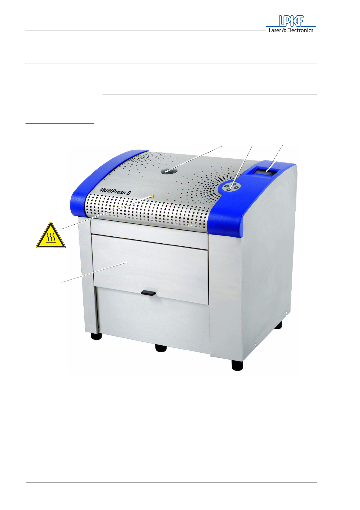
Fig. 1: MultiPress S Front View
2.1 MultiPress S
The multilayer press consists of the following operating units and
connecting elements:
123
4
5
1 Screw thread for lifting ring
(with covering)
2 Control keys
3 LCD-Display
4 Warning label: Hot surfaces
5 Sliding door
16 MultiPress S Operating manual 3.0 Rev: 3.6.2009
Page 19
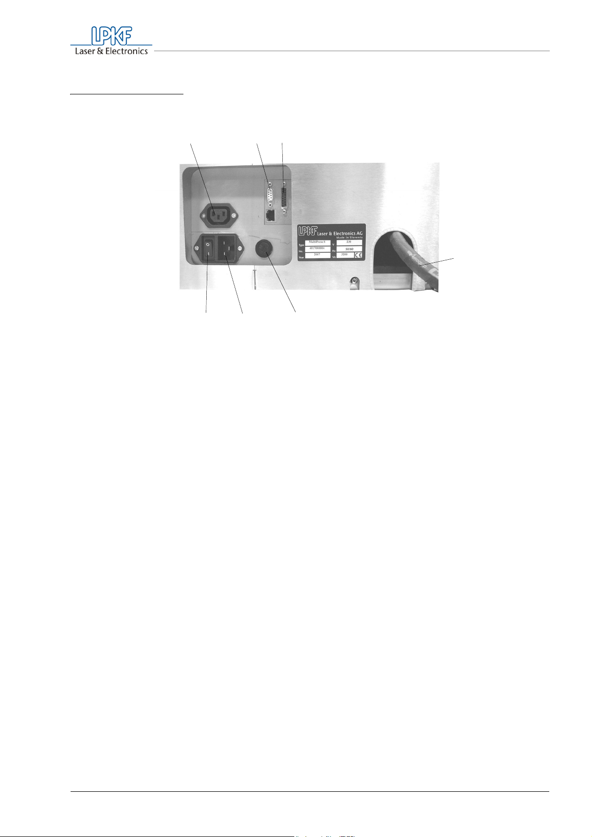
Fig. 2: MultiPress S connections on the back
What is what?
1
23
567
1 Mains outlet socket for automatic hydraulic
pump
2 Data cable connection for service labor
3 Connection for data cable to automatic
hydraulic pump
4
4 Hydraulic hose
5 230 V_fuse
6 Mains connection
7 Main switch
MultiPress S Operating manual 3.0 Rev 3.6.2009 17
Page 20
What is what?
WARNING
2.2 Automatic hydraulic pump
Risk of injury!
Under high pressure standing leaky fittings can solve
uncontrollably. Spouting hydraulic oil can cause eye and skin
injuries.
Switch off the MultiPress S before tightening/loosening the screw
connetion of the hydraulic hose.
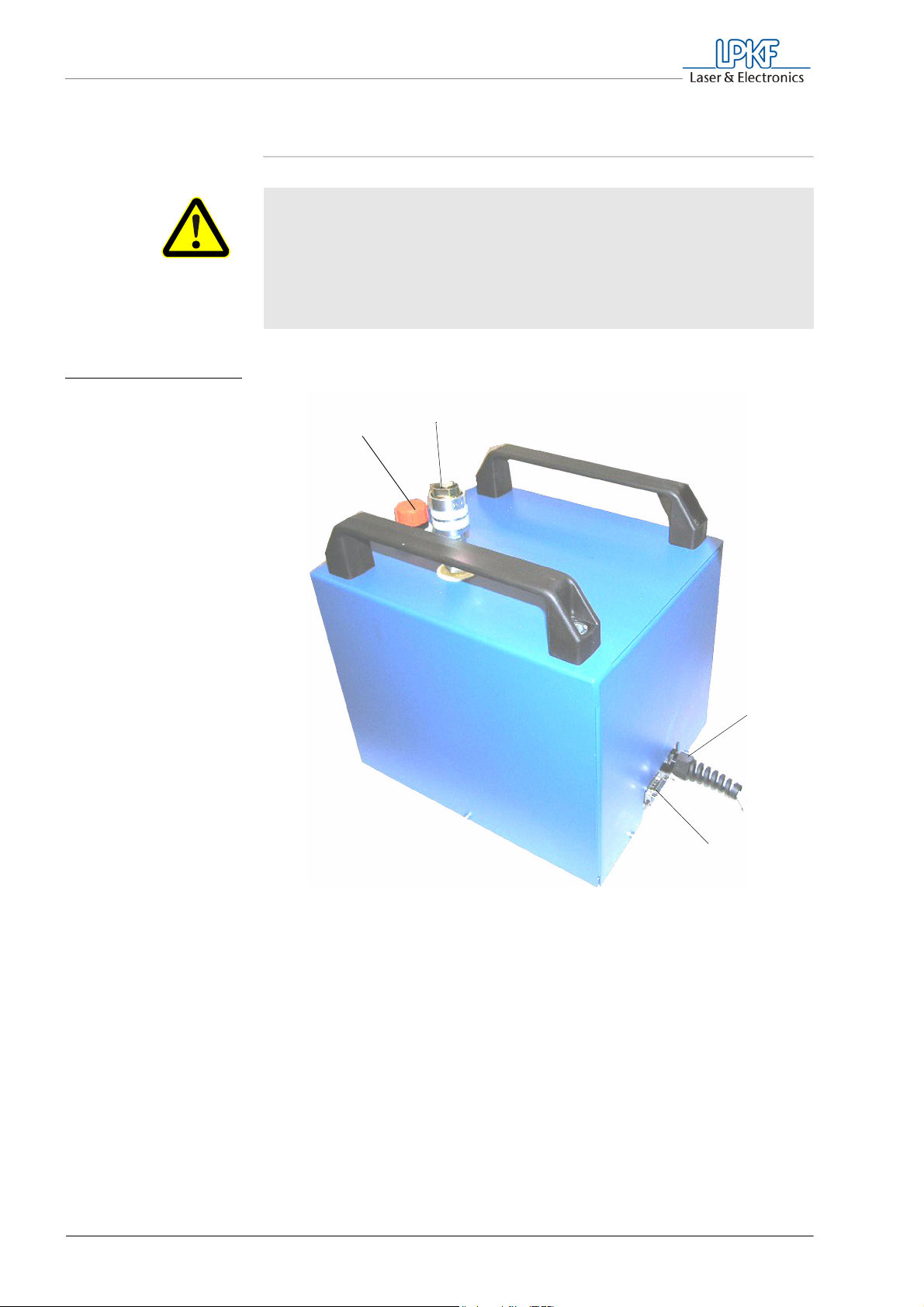
Fig. 3: Automatic
hydraulic pump
2
1
3
4
1 Filler neck for hydraulic oil
2 Connection for hydraulic hose
18 MultiPress S Operating manual 3.0 Rev: 3.6.2009
3 Mains cable
4 Data cable with connecting socket
Page 21
WARNING
WARNING
What is what?
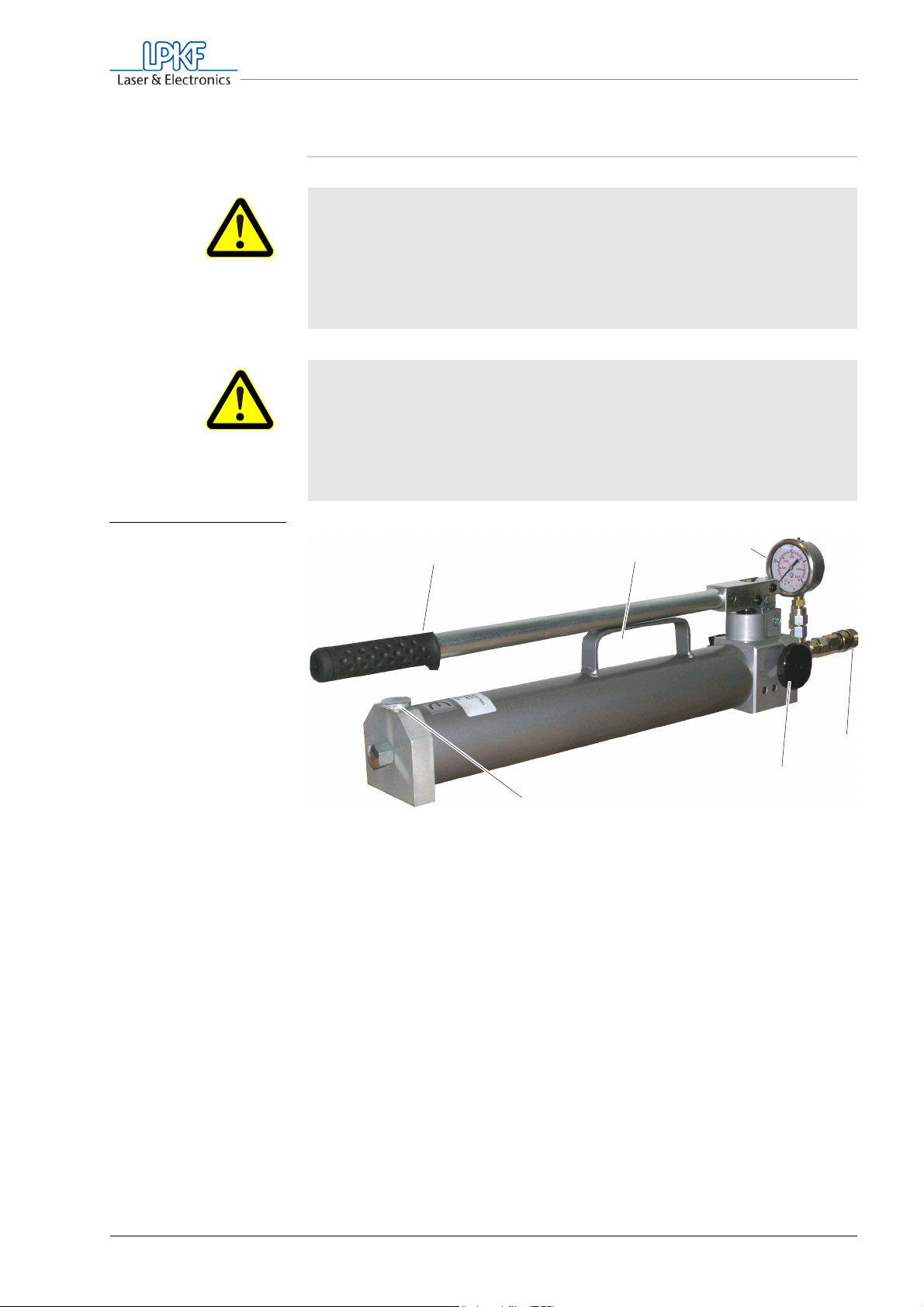
2.3 Hand pump
Risk of injury!
Under high pressure standing leaky fittings can solve uncontrol-
lably. Spouting hydraulic oil can cause eye and skin injuries.
Switch off the MultiPress S and ensure that the manometer on the
hand pump shows 0 bar (0 psi) before tightening/loosening the
screw connetion of the hydraulic hose.
Risk of crushing.
During pumping the pumping lever is lowered down to the
carrying handle. This may result in limbs being crushed between
the lever and the carrying handle.
During pumping, do not hold the hand pump on the carrying
handle.
Fig. 4: Hand pump
1 Pump lever
2 Carrying handle
3 Manometer
123
4
5
6
4 Threaded connection for hydraulic hose
5 Handwheel for pressure relief valve
6 Screw cap for oil tank
MultiPress S Operating manual 3.0 Rev 3.6.2009 19
Page 22
What is what?
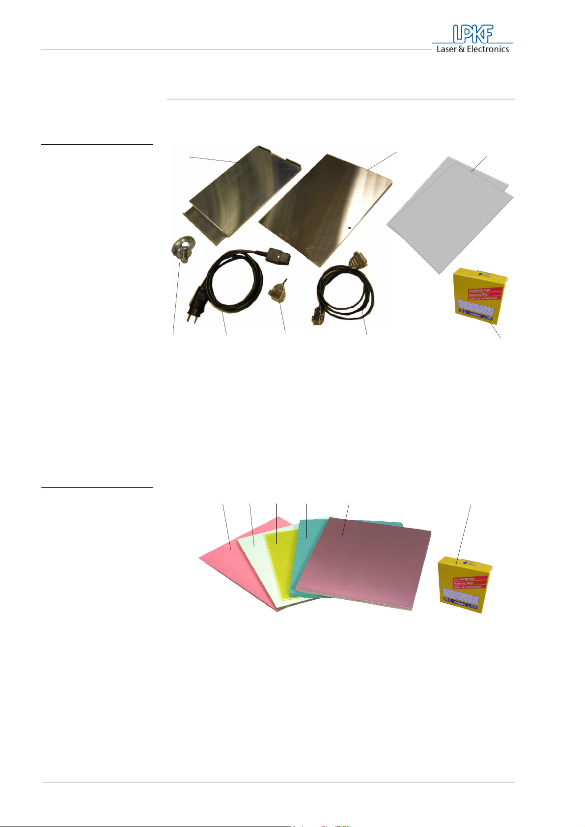
2.4 Accessories
Included in delivery
Fig. 5: Accessories
1
8
1 Lower press mold
2 Upper press mold
3 Press cushion (gray fibre)
Consumables (not included in delivery)
4 Sealing rings
5 Data cable for optional pump
6 Dummy plug
2
3
56 47
7 Mains cable
8 Lifting ring
Fig. 6: LPKF multilayer set
Disclaimer LPKF will not be responsible for damage and malfunction caused by the
For safe and reliable operation of the multi-press S we recommend the
original LPKF base materials and consumables. These are available as
economical multilayer sets or in single packing for different applications.
1A2 3
1 Laminate Multilayer 0/5 µm according to
appliance with or without protection foil
2 Prepreg (yellow)
A) press cushions - included in delivery
4
3 Press cardboard (blue)
4 Core material FR4 18/18 µm
5 Sealing rings
5
use of other materials/consumables.
20 MultiPress S Operating manual 3.0 Rev: 3.6.2009
Page 23

Installation/Putting into operation
3. Installation/Putting into operation
Read this chapter and observe the safety instructions before installing the
MultiPress S and putting it into operation. This is the only way to
guarantee the correct functioning and safe operation of the MultiPress S.
Ambient conditions Observe the following installation and ambient conditions (see also
Chapter 10‚ "Technical Data", on page 67).
• Operate the machine in dry rooms only.
• Protect machine from splash water.
• Protect the 230 V mains power supply with a C 16 A fuse.
• Install machine only on a working surface of at least 250 kg (441 lbs).
• Ensure at least 15 cm (38") of free space on all sides of the press.
Required tools and materials
• Material for supporting the press during the dismounting of the
shipping braces, e. g. three pieces of squared timber (15 cm x 15 cm
x 60 cm)
• To position the press on the benchtop, a mobile crane or a lifting
device having a minimum carrying capacity of 250 kg is required.
Tip: If no mobile crane is available, we recommend the use of a
mobile work table, which can be placed under the lifted
MultiPress S.
3.1 Building up the machine
The machine is secured on the pallet with shipping braces and is
delivered in several individual parts.
Keep all packaging materials and reuse them the next time the machine
is transported.
MultiPress S Operating manual 3.0 Rev 3.6.2009 21
Page 24

Installation/Putting into operation
WARNING
WARNING
CAUTION
3.1.1 Placing the multilayer press
Personal injury caused by excessive physical stress.
The MultiPress S weighs 170 kg (375 lbs). Lifting it manually can
overstress the spinal column and cause permanent damage.
For the installation of the MultiPress S, use a crane or a lifting
device.
Observe the maximum allowed loads.
Danger caused by suspended loads.
The lifted press may fall down and cause serious injury.
When dismounting the shipping braces, protect the press against
falling down.
Risk of material damage.
The high weight of the press can result in damage when handled
improperly.
Do not tilt or knock the press nor subject it to excessive shaking.
Fig. 7: Removing shipping
braces from pallet,
inserting lifting ring
1
1 Removing the screws 2 Screwing in the lifting ring
22 MultiPress S Operating manual 3.0 Rev: 3.6.2009
Page 25

Installation/Putting into operation
› Remove the bolted connections between steel bracket and pallet (1).
› Remove the rubber cover on the top of the MultiPress S and screw in
the delivered lifting ring by hand as far as it will go (2).
› Lift the MultiPress S by means of a (mobile) crane or a lifting device
from the pallet.
Removing the shipping
brace
WARNING
The steel bracket at the bottom of the press serves as shipping brace. It
must be removed from the bottom side, before placing the press at the
place of use.
› Secure the press such that it cannot fall down.
For example, place it on sufficiently stable, horizontal squared
timbers (15 cm x 15 cm x 60 cm). Make sure that the press stands
on all six rubber legs.
› Remove the screws that fasten the steel bracket from below to the
bottom plate of the press.
› Lift the press by crane and position it on the work table.
› Align the adjustable legs of the MultiPress S such that the machine is
level and the weight is distributed on all legs.
› Remove the lifting ring from the MultiPress S and close the threaded
opening with the rubber cover.
Risk of burns.
The screwed in lifting ring becomes very hot during operation
of the MultiPress S and can cause burns.
Before putting the MultiPress S into operation, ensure that the
lifting ring is removed and the rubber covering is put on the
screw thread.
MultiPress S Operating manual 3.0 Rev 3.6.2009 23
Page 26

Installation/Putting into operation
3.1.2 Installing the hydraulic pump
Depending on equipment, the MultiPress S is delivered with an automatic
hydraulic pump or with a hand pump.
Installing the automatic hydraulic pump
› Position the automatic hydraulic pump such that the hydraulic hose
and cables can be laid without producing kinks and causing a risk of
stumbling.
› Connect the hydraulic hose of the MultiPress S to the connection for
the hydraulic hose on the automatic hydraulic pump.
› Secure the connection by tightening the spigot nut by hand.
› Connect the automatic hydraulic pump to the MultiPress S using the
data cable delivered with the MultiPress S.
› Plug the IEC non-heating appliance plug of the pump into the mains
outlet socket of the MultiPress S.
Installing the hand pump
› Make sure that the pressure relief valve (see "Hand pump" on
page 19) is closed. To do so, rotate the handwheel clockwise as far
as it will go and tighten it by hand.
› Position the hand pump next to the MultiPress S. Make sure that the
hydraulic hose can be laid without producing kinks and causing a risk
of stumbling.
› Insert the hydraulic hose of the MultiPress S into the hydraulic pump
outlet of the pump and secure the connection by tightening the spigot
nut by hand.
› Plug the dummy plug into the data output socket of the MultiPress S.
24 MultiPress S Operating manual 3.0 Rev: 3.6.2009
Page 27

WARNING
Installation/Putting into operation
3.2 Putting the machine into operation for the first time
Risk of burns.
The screwed in lifting ring becomes very hot during operation of
the MultiPress S and can cause burns.
Before putting the MultiPress S into operation, ensure that the lif-
ting ring is removed and the rubber covering is put on the screw
thread.
In order to guarantee the safe operation of all machine components, first
the basic functions must be set, and the safety devices must be tested.
› Plug the mains connecting line of the MultiPress S into a grounded
mains 230 V socket protected with a 16 A fuse.
› Switch the main switch on the rear of the MultiPress S to the
position I.
Fig. 8: Start message
The display lights up and shows the following message:
Haup t menü LPKF Se t
P r o f i l e
Se t up ENT
2 0 °C 20 °C
MultiPress S Operating manual 3.0 Rev 3.6.2009 25
Page 28
Installation/Putting into operation
3.2.1 Setting the language
To show display messages in a different language, proceed as follows:
› Select the menu item Setup using the selection keys.
› Press the ENT key
At top left, "Setup" is displayed.
› Select the menu item Sprache using the selection keys.
› Press the ENT key.
In the top left display box, "Sprache" is displayed.
› Select the desired language using the selection keys.
› Press the ENT key.
The display is shown in the selected language.
3.2.2 Testing the safety devices
In order to guarantee the safe operation of the MultiPress S, during
commissioning and regularly after one month, the safety devices must be
tested for their function.
Information on the menu guidance can be found in Chapter 6‚
"Operation", on page 37.
Testing program interruptions opening the sliding door
The programs may only be started with the sliding door closed.
› Open the sliding door
› In the main menu, select the entry Start.
› Press the ENT key.
"start" appears in the menu box, and the entry Preheating is
preselected.
26 MultiPress S Operating manual 3.0 Rev: 3.6.2009
Page 29

Installation/Putting into operation
› Press the ENT key.
An acoustic signal sounds, and the LCD display reports "flap open". If
the program starts despite open sliding door, contact the LPKF
Support.
› To cancel the program and finish the test, press the ESC key.
Testing the pressure limit of the hand pump
To protect the mechanical components from overload, not more than
300 bar (4350 psi) of pressure may be built up. This is what the pressure
limiting valve integrated in the hand pump is for.
› Make sure that the pressure relief valve (see fig. 4 on page 19) is
closed. To do so, rotate the handwheel clockwise as far as it will go
and tighten it by hand.
› Pump using the lever until the manometer shows 300 bar (4350 psi).
› Keep pumping with the lever.
The displayed pressure must not rise beyond 300 bar (4350 psi).
› If the displayed pressure rises beyond 300 bar (4350 psi), contact the
LPKF Support.
› Rotate the handwheel counterclockwise, to lower the hydraulic
pressure and finish the test.
MultiPress S Operating manual 3.0 Rev 3.6.2009 27
Page 30

For your notes
28 MultiPress S Operating manual 3.0 Issued: 3.6.2009
Page 31

4. What you should know
This chapter gives you general information on the structure of a
multilayer and the materials required for constructing it. In addition, you
will learn about the individual stages of the press process, which will
allow you to configure later on special press profiles for different
applications and materials.
Tip: Detailed information on special applications, materials tested by
LPKF and tips for optimum processing can be obtained from the LPKF
Support.
4.1 Structure of a multilayer
In order to produce a multilayer as thin as possible, we recommend the
use of the following LPKF materials.
What you should know
Inner layers Multilayer comprising four layers:
Base material FR4 18/18 µm, 1.0 mm (40 mil) thick, coated on both
sides.
Multilayer comprising six and eight layers:
Base material 104 ML 18/18 µm, 0.36 (14 mil) thick, coated on both
sides.
Outer layers: For galvanic through hole conductivity:
Laminate 104 ML, 5/0 µm, 0.2 mm thick, coated on one side, including
protective film.
For chemical free through hole conductivity with LPKF ProConduct:
Laminate 104 ML, 0/18 µm, 0.2 mm thick, coated on one side, including
protective film.
Composite material Prepreg (pre-impregnated, insulating fiber material), 0,1 mm (4 mil) thick.
Depending on application and further processing, it may be necessary to
mill and drill the materials before and/or after the press process.
Depending on layout, one or two layers of prepreg may be required
between the individual layers (see chapter 6.6.2‚ "Assembling the
multilayer in the press mold", on page 50).
MultiPress S Operating manual 3.0 Rev 3.6.2009 29
Page 32

What you should know
n
Fig. 9: Structure of a
multilayer
comprising four
layers
WARNING
Laminate 104 ML
(unprocessed)
1x/2x Prepreg
Core material
(double-sided processi
1x/2x Prepreg
Laminate 104 ML
(unprocessed)
4.2 Materials
Risk of fire caused by using non-approved materials.
The high temperatures during the press process can set
unsuitable materials in the press on fire.
Use only materials approved for multilayers and observe the
application information in the data sheets.
We recommend the use of the LPKF multilayer kits. They contain all
materials required for the pressing of a multilayer, including the
consumables required for the press process.
4.2.1 Material storage and preparation
Given the large number of multilayer materials available on the market,
we can only give general information on the material storage and
application. In order to obtain optimum results, you should observe the
following measures.
• Read the data sheets on the materials and application information.
• Store the materials in a cool and dry place.
• Store the materials in horizontal position, in order to guratantee their
dimensions stability and exclude distortion.
30 MultiPress S Operating manual 3.0 Rev: 3.6.2009
Page 33
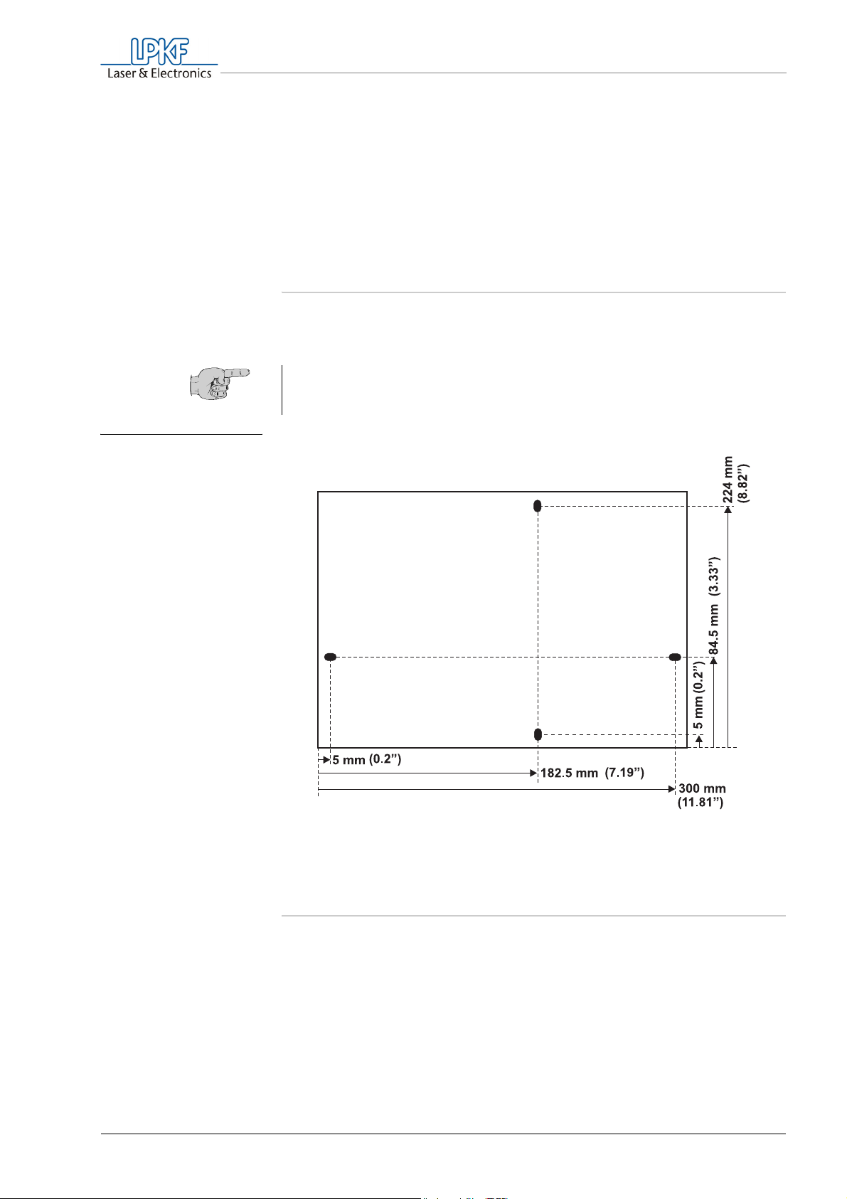
Fig. 10: Bore spacings for
fiducial bores
What you should know
• Observe the use-by dates.
• Prior to processing, store the materials at room temperature for at
least 24 h.
• Prepare the materials according to the manufacturer's data (drilling
fiducials, cleaning, heat treatment, cutting to size, if required,
observing the fiber direction).
4.2.2 Fiducial bores
In order to be able to insert base materials and laminates into the press
mold, they must be provided with long holes (3.0 mm x 5.0 mm). .
Tip: If the individual layers are produced using a circuit board plotter,
the bore data can be integrated in the printed circuit board layout or
made available as independent file.
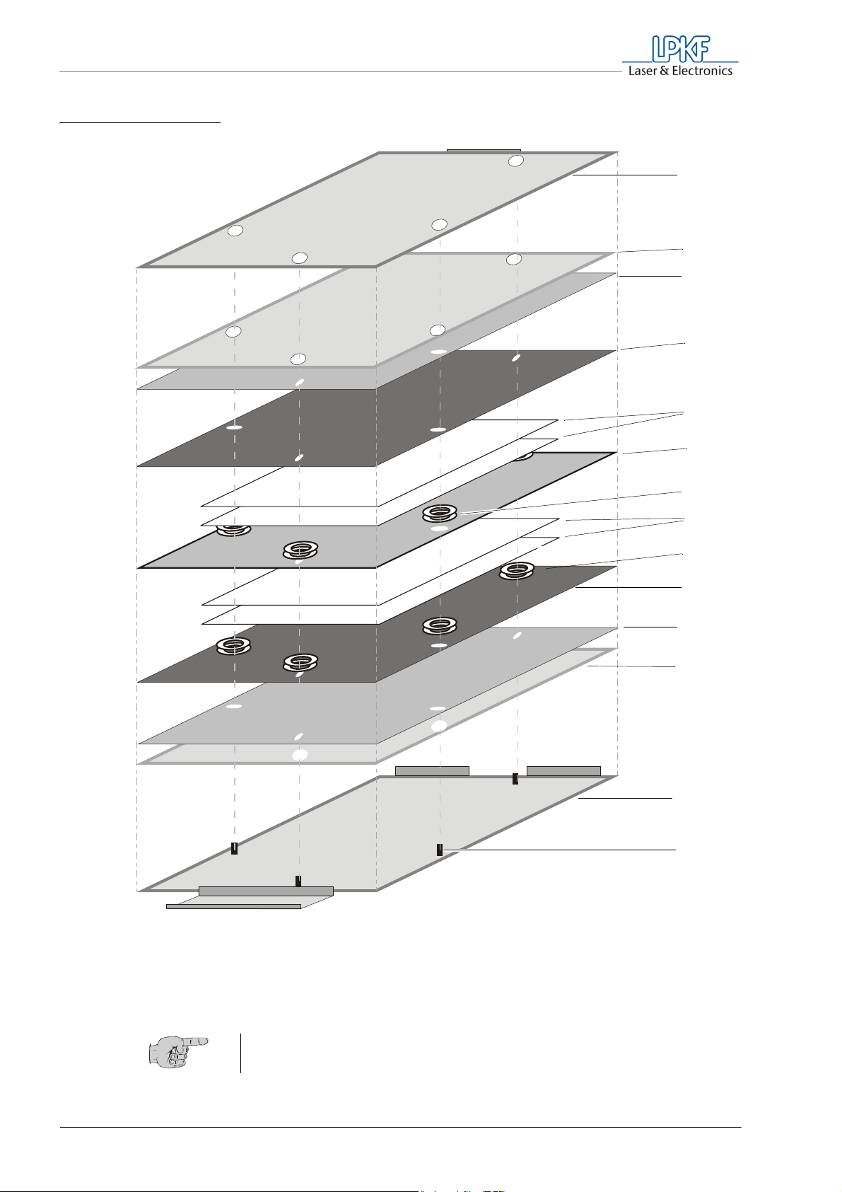
4.3 Assembly of a multilayer
The multilayer materials must be assembled for the press process in the
press mold developed especially for the MultiPress S. The press mold
consists of the two aluminum parts with dowel pins. Press sheets and
cushions guarantee an optimum pressure distribution in the press mold.
MultiPress S Operating manual 3.0 Rev 3.6.2009 31
Page 34
What you should know
Fig. 11: Multilayer in Pressform
1
2
3
4
5
6
10
11
12
13
14
7
8
9
1 Press mold (upper part)
2 Press cushion
3 Press sheet
4 Laminate
(Laminate on upper side)
5 Prepreg (1 or 2 layers)
6 Core material
7 Sealing rings (1-/2 rings
8 )Prepreg (1 or 2 layers)
9 Sealing rings (1-/2 rings
10 Laminate
(Laminate on lower side)
11 Press sheet
12 Press cushion
13 Pressmold (lower part)
14 Passhole pins in press
mold
Tipp: In order to avoid skin fat deposit and dust on the materials, you
should work with fluff-free gloves.
32 MultiPress S Operating manual 3.0 Rev: 3.6.2009
Page 35

5. Mode of operation
The press process is executed via menu-controlled programs. During a
program run, the process goes through various heating and pressing
stages, which are defined as press profiles. Acoustic signals and display
messages announce the various pressing stages. The following
programs (press profiles) are available:
• LPKF Set containing a permanently configured press profile for
pressing multilayers comprising four, six and eight layers using LPKF
standard materials in standard size.
• Profile1 to Profile6 containing freely configurable press profiles for
special applications, materials and layout sizes.
In the MultiPress S with automatic hydraulic pump, the heating and
pressing stages are carried out automatically.
In the MultiPress S containing a hand pump, the pressure must be built
up before each pressing stage and controlled and tracked during the
entire press process. Display messages and acoustic signals indicated
required manual interventions, e. g. for inserting the material, and give
information on the stage change during the press process.
Mode of operation
Note: After inserting the multilayer into the press, the program sequence
must not be interrupted, since otherwise the pressing quality cannot be
guaranteed. Interrupt a pressing in case of an emergency only.
5.1 Press profiles
Press profiles contain the data for temperature, pressure, press times
and material size required for a press process. A press process always
takes place in several stages of different lengths of duration depending
on the press profile. In these stages, different temperatures and
pressures are established.
5.1.1 Heating and pressing stages
Operating the MultiPress S with automatic hydraulic pump, the stages
are carried out automatically after inserting the material.
In the MultiPress S containing a hand pump, the pressure required for
each stage must be built up manually and controlled and tracked during
the stage sequence. This is true in particular of the beginning of the main
pressing stage and during the entire cooling stage.
MultiPress S Operating manual 3.0 Rev 3.6.2009 33
Page 36
Mode of operation
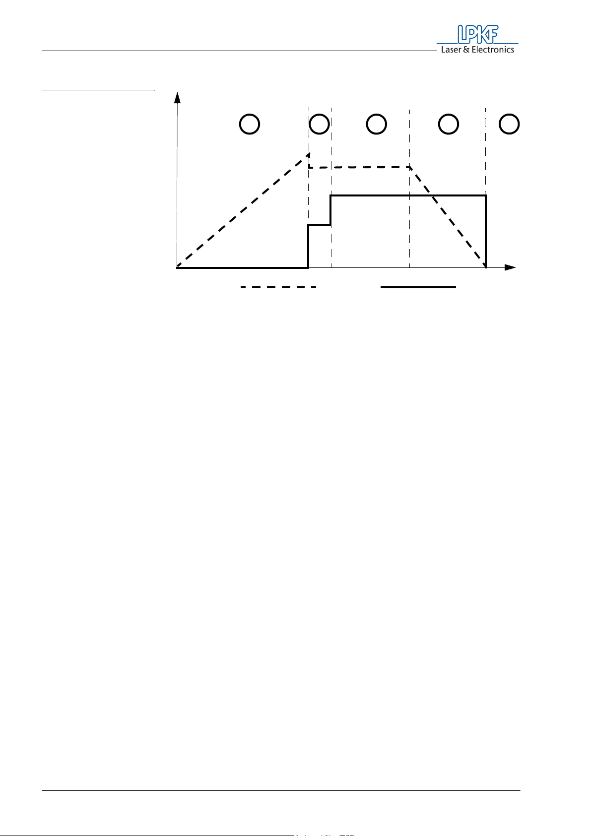
Fig. 12: Pressing stage
sequence
1
2
34
5
Temperature:
1 Preheating stage
2 Prepressing stage
3 Main pressing stage
Preheating stage (1) In the preheating stage, the press is heated up in the absence of a
Pressure:
4 Cooling stage
5 Curing stage
multilayer to the temperature specified in the press profile.To avoid
temperature losses and quickly reach the preheating temperature, for the
MultiPress S with automatic hydraulic pump, first the press jaws are
moved toward each other. In the MultiPress S containing a hand pump, a
pressure of 10 bar should be built up to this end. After the preheating
temperature has been reached, the multilayer assembled in the press
mold must be pushed into the press.
Note: The preheating temperature should be set higher than the main
pressing temperature, since the temperature clearly drops when the
press mold is inserted.
Time
Prepressing stage (2) The prepressing stage must be started manually. It is required so as to
allow air bubbles trapped between the layers during the increase in
temperature to escape.
Note: The prepressing time depends on the prepreg and should be at
least 1 minute, to allow the adhesive to melt uniformly.
Main pressing stage (3) In the main pressing stage, the actual pressing of the layers constituting
the multilayer takes place. Temperature and pressure must remain
constant over the entire main pressing stage.
Cooling stage (4) During the cooling stage, the temperature is slowly lowered to ambient
temperature. To avoid air inclusions in the still soft prepreg adhesive, it is
absolutely necessary to keep the pressure constant.
Note: The dropping temperature causes the material to contract, so that
the pressure must be adjusted accordingly. This is why for the
MultiPress S containing a hand pump, the pressure must be checked by
means of the manometer during the entire cooling stage and, if
necessary, corrected by additional pumping.
34 MultiPress S Operating manual 3.0 Rev: 3.6.2009
Page 37
Mode of operation
Curing stage (5) After its removal, the multilayer must rest at room temperature for at least
16 h, to allow the adhesive to cure completely.
Note: An incompletely cured adhesive can smear the inner layers during
drilling, thus no longer guaranteeing proper through-hole plating.
5.1.2 Configuration
The MultiPress S is equipped with a permanently configured LPKF press
profile and six freely configurable profiles.
LPKF Set The press profile LPKF Set can be used for standard multilayers
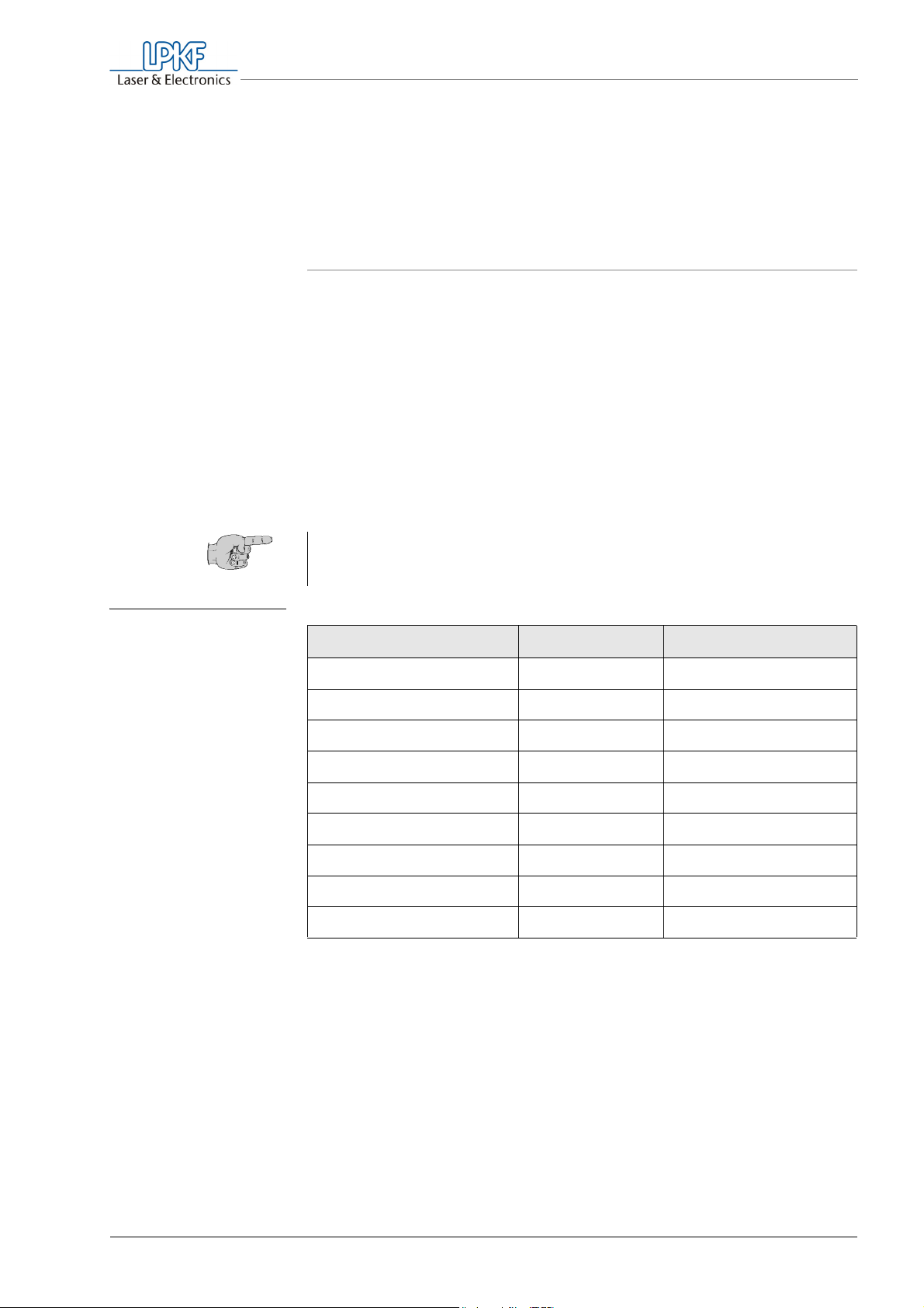
comprising 4,6 and 8 layers of layout 200 x 275 mm (7.87“ x 10.83“)
guarantee optimum processing at the parameters listed in table 1, the
base material must have a size of 305 x 229 mm (12" x 9").
Variable profiles The press profiles available for individual configuration Profile 1 –
Profile 6 have been preset to the parameters listed in table 1. In this way,
depending on the requirements, only few changes must be made.
. To
Tab. 1: Preset pressing
parameters
Tip: Write down the parameters that you have changed. The Appendix
contains a table in which you can enter the parameters required for
your applications.
Parameters LPKF 1
Preheating temperature 250 °C 250 °C
Prepressing temperature 180 °C 150 °C
Main pressing temperature 180 °C 180 °C
Prepressing time 10 min 10 min
Main pressing time 60 min 30 min
Prepressing force 80 N/cm² 80 N/cm²
Main pressing force 150 N/cm² 100 N/cm²
Width 305 mm 305 mm
Height 229 mm 229 mm
Profile 1 – Profile 8
MultiPress S Operating manual 3.0 Rev 3.6.2009 35
Page 38

For your notes
36 MultiPress S Operating manual 3.0 Issued: 3.6.2009
Page 39

6. Operation
Operation
6.1 Switching on the machine
To build up sufficient pressure and to avoid oil loss, before every usage of
the machine the hydraulic connection on the pump must be checked for
adequate fastness.
› Make sure, that the coupling nut on the hydraulic connection of the
pump is fastened hand sturdy
› Switch the main switch on the rear of the MultiPress S to the
position I.
Note: The automatic hydraulic pump is supplied with power via the
MultiPress S and is switched on and off together with it.
The display will show the main menu with the press profile selected
last.
6.2 Operating the control using the selection keys
The press profiles are selected and programmed by means of the
selection keys on the menu-controlled LCD display.
6.2.1 Display boxes in the LCD display
Depending on the operational status, the display is divided into different
boxes. After switching on, the main menu showing the selection options,
the press profile selected last and the temperature at the upper and lower
press jaw is displayed.
MultiPress S Operating manual 3.0 Rev 3.6.2009 37
Page 40
Operation
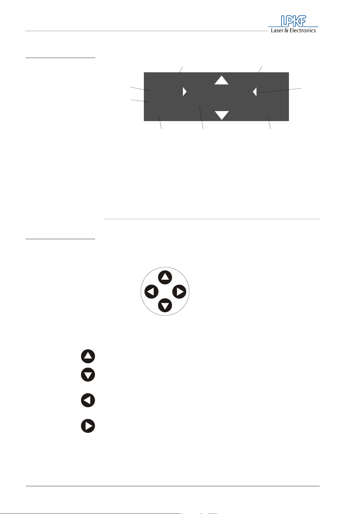
Fig. 13: Display boxes in
the machine ready
state
12
me n u e L P K F s e t
(8)
S e t u p
(7)
s t a r t ENT
2 0 ° C 2 0 ° C
456
1 Menu box
2 Profile box
3 Selection box
4 Current temperature lower
press jaw
5 Selection list
Information on the display during a press process can be found in
Chapter 6.5‚ "Starting the program", on page 43.
6.2.2 Selection keys
Use the selection keys to select and confirm menu items.
6 Current temperature upper press jaw
7 Error description (only when error
occurs)
8 Error code (only when error occurs)
3
Fig. 14: Function of the
selection keys
Selection key
Up
ESC
ENT
Selection key
Down
› Press the Up selection key, to move the selection one step upwards.
› Press the Down selection key, to move the selection one step
downwards.
› Press the ESC key, to return to the previous selection or to cancel a
program.
› Press the ENT key, to confirm the menu selection.
38 MultiPress S Operating manual 3.0 Rev: 3.6.2009
Page 41

Operation
6.2.3 Selecting menu entries
After switching on, the press displays the main menu containing the
entries Start, Setup, Profiles and Service.
Displaying the main menu
› If the main menu ("menue“) is not displayed, press the ESC key
repeatedly until "menue" appears in the menu box.
Selecting a menu item
› Press the Up or Down key repeatedly until the desired menu item
appears in the selection box.
› Press the ENT key, to confirm the menu selection.
The selected menu item is displayed in the menu box. The selection
box displays additional menu items, which again can be activated by
selecting and confirming them.
Canceling the selection
› To cancel a menu selection and return to the selection menu, press
the ESC key.
MultiPress S Operating manual 3.0 Rev 3.6.2009 39
Page 42
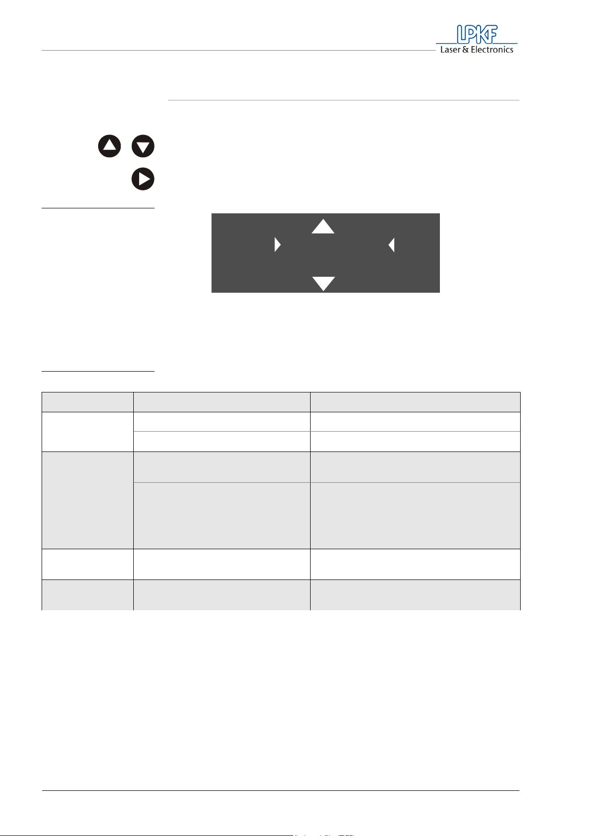
Operation
6.3 Setting the basic functions
To edit the basic functions, proceed as follows:
› In the main menu, select the entry Setup.
› Press the ENT key.
"Setup" appears in the menu box.
Fig. 15: Display in the
Setup menu
S e t u p LPKF s e t
L a n g u a g e
ESC p r e h e a t ? EN T
2 0 ° C 2 0 ° C
› Select the desired entry in the selection list and press the ENT key.
The selection options are explained in Table 2 on page 40.
Tab. 2: Setup menu
Menu item Selection options Function/Explanation
Language
preheat?
German (Factory setting) Display in German
English Display in English
Off (Factory setting) Preheating stage can only be started
manually.
On The preheating stage is started
automatically with the profile selected last,
after switching on the MultiPress S on the
main switch. Activate this option only if
you always use the same profile.
firmware
Software version is displayed in the
selection box
hours
The number of previous operating hours
is displayed in the selection box
(Table page 1 of 2)
40 MultiPress S Operating manual 3.0 Rev: 3.6.2009
Page 43
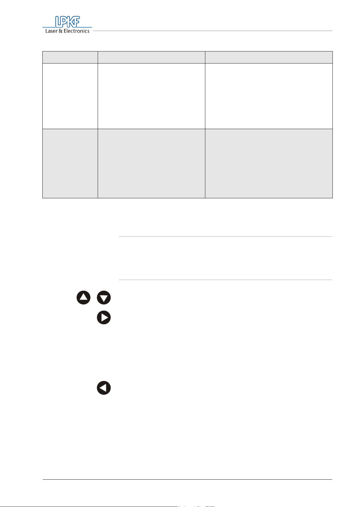
Menu item Selection options Function/Explanation
Operation
fan temp.
service
(Table page 2 of 2)
Temperature in °C
Factory setting: 40°C
Change the digits using the
selection keys and confirm by
pressing the ENT key. After
confirming the last digit, you are
back in the Setup menu.
Enter the 5-digit numeric code,
confirming each digit by pressing
ENT.
6.4 Selecting and editing press profiles
Active cooling stage (fan operating mode)
is finished when the temperature on the
press jaws has dropped to the fan
temperature.
Note: Do not set the fan temperature to a
smaller value than the ambient
temperature, since otherwise the cooling
stage will not be finished automatically.
Test and calibration functions.
Changes not approved by LPKF can
result in malfunctions and damage to the
device.
They may only be carried out by
authorized personnel.
To start a program or to change the parameters of a press profile, first the
desired press profile must be selected.
6.4.1 Selecting a press profile
› In the main menu, select the entry Profile.
› Press the ENT key.
"profiles" appears in the menu box.
› Select the menu item Select and press the ENT key.
"select" appears in the menu box.
› Select the desired press profile and press the ENT key.
The desired press profile is displayed in the profile box.
› Press the ESC key, to return to the Profiles menu.
MultiPress S Operating manual 3.0 Rev 3.6.2009 41
Page 44

Operation
6.4.2 Editing the press profile
Only the Profile 1 - Profile 6 press profiles can be edited. LPKF Set is
designed especially for the production of multilayers comprising four to
eight layers using LPKF base materials in the standard format and cannot
be changed.
The values of a press profile are changed as follows:
› Make sure that the desired profile is displayed in the profile box.
› In the Profile menu, select the entry change.
› Press the ENT key.
"change" appears in the menu box.
› Select the desired entry and press the ENT key.
For the explanation of the entries, please refer to Table 3 on page 43.
The current value is shown in the selection box.
› Use the selection key, to change a digit.
› Press the ENT key, to confirm the menu selection and to switch to
the next digit.
After confirming the last digit, you are back in the Change menu.
Note: If the entered value is outside the in-factory limit, the message
"input correction" will appear, after the last digit has been confirmed,
and the allowed maximum or minimum value will be set. The
correction message will go out after 20 seconds.
42 MultiPress S Operating manual 3.0 Rev: 3.6.2009
Page 45
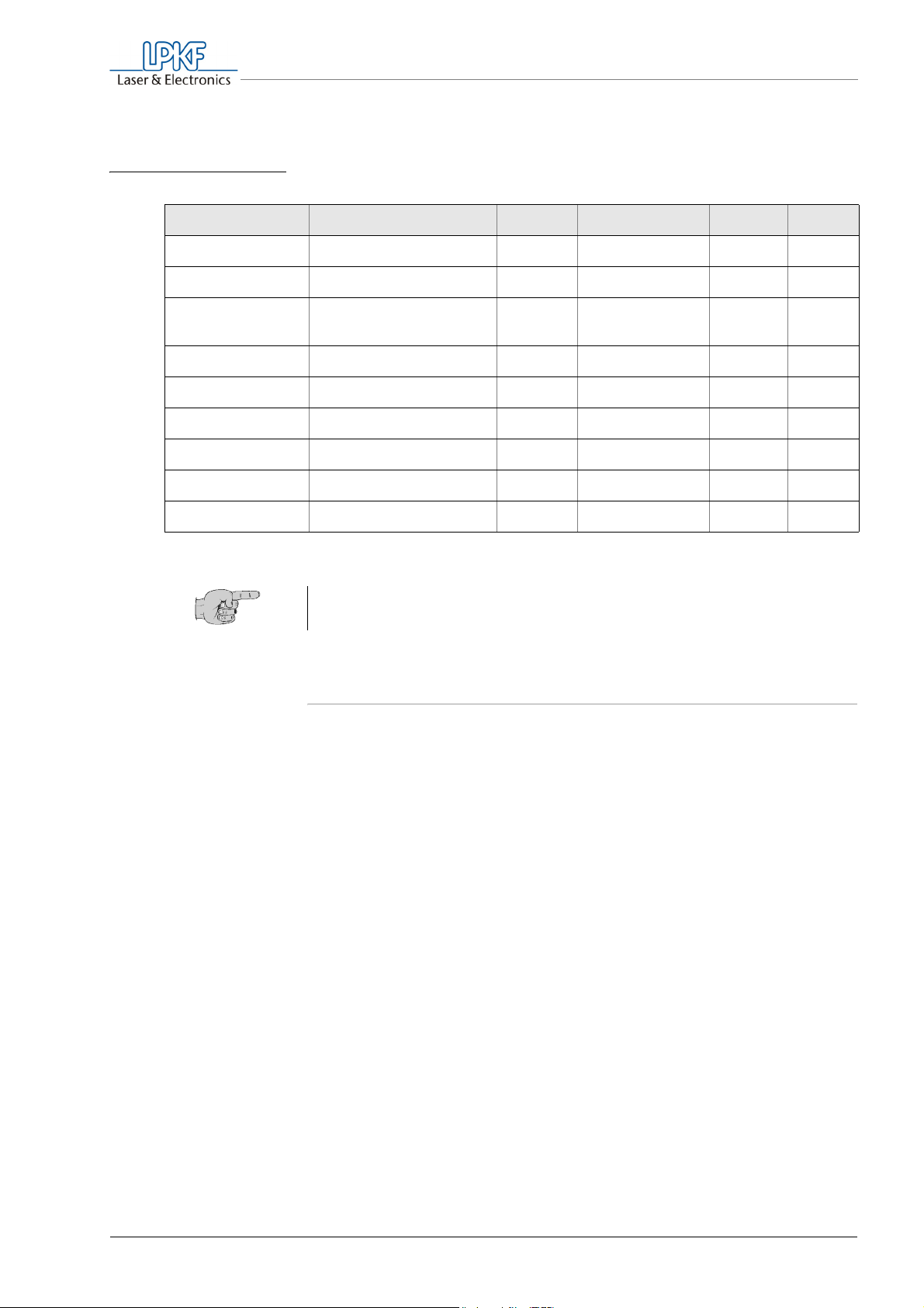
Tab. 3: Menu Profiles > Change
Menu item Function/Explanation Unit Preset min. max.
Operation
The following values can be changed in the press profiles:
prehe.temp Preheating temperature
prepre.temp Prepressing temperature
presstemp Main pressing
temperature
width Width of the multilayer
height Length of the multilayer
pp-force Prepressing force
mp-force Main pressing force
preptime Prepressing time
presstime Main pressing time
Tip: Use the Table 6, "Individual configuration of the press profiles", on
page 72, to log the changed values.
6.5 Starting the program
°C 250 30 250
°C 150 30 250
°C 180 30 250
mm 305 100 305
mm 229 100 229
N/cm² 80 30 286
N/cm² 150 30 286
min 10 1 60
min 60 1 120
MultiPress S with hand
pump:
A program is started using the press profile shown in the profile box (see
"Selecting and editing press profiles" on page 41). Please note that the
press profile selected last is automatically preselected, after switching on
the MultiPress S.
Note: Prior to pressing, the multilayer materials and consumables must
be stored at room temperature for 24 hours, cleaned and heat-treated.
Observe the information given in Chapter 6.6.1‚ "Preparing the
materials", on page 50.
Before starting a press program, observe the information on the
operation of the hand pump (see chapter 6.8‚ "Operating the hand
pump", on page 54) and familiarize yourself with its use.
MultiPress S Operating manual 3.0 Rev 3.6.2009 43
Page 46

Operation
6.5.1 Starting the preheating stage
The preheating stage can be switched on automatically when the
MultiPress Sis switched on and/or started manually.
Bringing the press jaws together
In order to reach the target temperature as quickly as possible, the press
jaws should be closed during the preheating state. This is done in the
MultiPress S program-controlled by means of the automatic hydraulic
pump.
› In the MultiPress S with hand pump:
Pump repeatedly until the manometer shows a pressure of 10 bar
(145 psi).
Starting the preheating stage automatically
› In the menu Setup > Preheating, select the entry On and press the
ENT key.
Fig. 16: Display during the
preheating stage
The preheating is started automatically when the MultiPress S is
switched on. Please note that the press profile selected last will be
used. (see table Tab. 2: „Setup menu“ on page 40).
Starting the preheating stage manually
› Make sure that the desired press profile is displayed in the profile
box.
› In the main menu, select the entry Start.
› Press the ENT key.
"start" appears in the menu box.
› Select the entry Preheating and press the ENT key.
The display shows the current data of the preheating state.
p r e h e a t L PKF S e t
2 5 0 ° C mu s t t e mp .
2 2 ° C u t e mp e r a t u r e
2 2 ° C l t e mp e r a t u r e
44 MultiPress S Operating manual 3.0 Rev: 3.6.2009
Page 47

Fig. 17: Display in the
Setup menu
Operation
Note: You can stop the preheating stage at any time by pressing the
ESC key, for example in order to select a different press profile or restart
the preheating stage at a later time.
After the preheating temperature defined in the press profile (must temp.)
has been reached, the Start menu is displayed, and the entry Pressing
is preselected. A short acoustic signal, repeated at an interval of three
seconds, indicates that the material should be inserted.
6.5.2 Starting the pressing stages
The prepressing stage must not be started until the preheating
temperature has been reached. Once the preheating stage is complete, a
repeated acoustic signal will sound, and in the Start menu the entry
Pressing is preselected.
s t a r t L PKF S e t
P r e s s
ESC f a n o n ENT
2 0 ° C 2 0 ° C
› Make sure that the desired press profile is displayed in the profile
box.
› Position the press mold containing the multilayer in the press.
chapter 6.6‚ "Loading the press system", on page 50)
(see
MultiPress S Operating manual 3.0 Rev 3.6.2009 45
Page 48

Operation
CAUTION
Material damage!
If the press process is interrupted, this may result in air
inclusions and material distortion in the multilayer.
Interrupt the press process only in case of emergency.
› Press the ENT key.
The press process is started with the prepressing stage. Note that
when using the MultiPress S with hand pump, the additional
operating steps for pressure build-up described below have to be
carried out.
The display box shows the following values:
Fig. 18: Display during the
pressing stages
(with automatic
hydraulic pump)
Fig. 19: Display during the
cooling stage (with
automatic hydraulic
pump)
12
p r e p r e s s LPKF S e t
(8)
2 5 0 / 2 0 ° C 3 0 5mm
(7)
8 0 N / cm2 2 2 9mm
6 0 mi n t i me = 0 0 : 5 9
56
1 Pressing stage
2 Press profile used
3 Material width
4 Material height
5 Remaining time for this
stage in hours:min
6 Pressing time
After the main pressing stage is complete, the cooling stage is started
automatically, and the fan is switched on. The display reports
"cool down" and shows the current temperatures at the upper and
lower press jaws.
7 Pressing force in N/cm² (with automatic
hydraulic pump)
or:
Target pressure in bar (with hand pump)
8 Target/actual temperature in °C
c o o l d own
8 0 N / cm2
u t e mp e r a t u r e 1 7 5 ° C
3
4
l t e mp e r a t u r e 1 7 5 ° C
46 MultiPress S Operating manual 3.0 Rev: 3.6.2009
Page 49

Operation
Pressure build-up using the MultiPress S with hand pump:
In the MultiPress S with hand pump, the pressure must be built up
manually at the beginning of each stage and corrected during the entire
program sequence(see chapter 6.8‚ "Operating the hand pump", on
page 54).
› As soon as the actual and target values appear, immediately start
pumping until the target value on the display is shown on the
manometer.
› In order to maintain the target pressure, correct the pressure during
the entire pressing.
At the end of the prepressing stage, a repeated acoustic signal will sound
indicating the beginning of the main pressing stage. In the pressing stage
display box, "main press" is displayed.
Fig. 20: Display during the
pressing stages
(with hand pump)
Fig. 21: Display during the
cooling stage (with
hand pump)
ma i n p r e s s LPKF S e t
2 5 0 / 1 8 0 ° C 3 0 5mm
1 4 7 b a r ma n u a l 2 2 9mm
6 0 mi n t i me = 0 0 : 5 9
› Keep pumping until the target pressure is shown on the manometer.
› Keep controlling the pressure and correct it, if necessary, by
additional pumping.
After the main pressing stage is complete, the cooling stage is started
automatically, and the fan is switched on. During this, the target pressure
is displayed, which must be maintained by additionally pumping by hand.
c o o l d own
1 4 7 b a r ma n u a l
u t e mp e r a t u r e 1 7 5 ° C
l t e mp e r a t u r e 1 7 5 ° C
During the cooling stage, it is particularly important to keep the pressure
at the target pressure level. Material-related, the pressure will drop
particularly strongly at the beginning of the cooling stage, at which point it
must be increased by additional pumping.
MultiPress S Operating manual 3.0 Rev 3.6.2009 47
Page 50

Operation
› Make sure that the pressure on the manometer always corresponds
to the target pressure during the entire cooling stage. If necessary,
correct it by additional pumping.
The cooling stage is finished automatically upon reaching the preset
fan temperature. A repeated acoustic signal will sound, and the
message "finished" will appear.
› Observe the information regarding the removal of the multilayer (see
chapter 6.6.4‚ "Removing the multilayer", on page 53).
Canceling/Quitting the program
A program in progress should only be stopped in case of emergency. If a
press process is interrupted, no matter during which stage, this may
result in air inclusions and material distortion in the multilayer. Thus, a
correct pressing can no longer be guaranteed.
To end a program prematurely, proceed as follows:
› Press the ESC key.
This immediately stops the program. The main menu is displayed,
and "preheat" is selected in the selection box.
› Observe the information regarding the removal of the multilayer (see
chapter 6.6.4‚ "Removing the multilayer", on page 53).
48 MultiPress S Operating manual 3.0 Rev: 3.6.2009
Page 51

Operation
6.5.3 Cooling the press system manually
In order to cool the press system quickly to the ambient temperature, for
example after a program cancel, the fan can be switched on manually.
› In the main menu, select the entry Start.
› Press the ENT key.
"start" appears in the menu box.
› Select the entry Fan on and press the ENT key.
Depending on equipment, the following information is displayed:
Fig. 22: Display during the
cooling stage (with
automatic hydraulic
pump)
Fig. 23: Display during the
cooling stage (with
hand pump)
c o o l d own
8 0 N / cm2
u t e mp e r a t u r e 1 7 5 ° C
l t e mp e r a t u r e 1 7 5 ° C
Co o l d own
1 4 7 b a r ma n u a l
u t e mp e r a t u r e 1 7 5 ° C
l t e mp e r a t u r e 1 7 5 ° C
The cooling stage is finished automatically upon reaching the preset fan
temperature. A repeated acoustic signal will sound, and the message
"finished" will appear.
› Observe the information regarding the removal of the multilayer (see
chapter 6.6.4‚ "Removing the multilayer", on page 53).
MultiPress S Operating manual 3.0 Rev 3.6.2009 49
Page 52

Operation
6.6 Loading the press system
To load the press system, the materials to be pressed must be prepared
and assembled in the press mold.
6.6.1 Preparing the materials
The multilayer materials and consumables must be cleaned and heattreated prior to processing. Follow the specific application information of
the material manufacturer and observe the following instructions.
Tip: In order to avoid skin fat deposit and dust on the materials, you
should work with fluff-free gloves.
• Remove materials from the packaging material 24 hours before
processing and store them horizontally at room temperature.
• If the base material and laminate do not yet have fiducials
corresponding to the press mold, they must be drilled (see
chapter 4.2.2‚ "Fiducial bores", on page 31).
• Clean the base materials and laminate with isopropanol or acetone.
• Heat-treat the base materials and laminates before pressing at
120 °C for 30 minutes.
• After the heat treatment, allow the materials to cool down for about
10 minutes and then assemble them quickly to the multilayer (see
chapter 6.6.2‚ "Assembling the multilayer in the press mold", on
page 50).
6.6.2 Assembling the multilayer in the press mold
While the press is being heated up, you have enough time to assemble
the multilayer in the press mold. Depending on the application, material
selection and layout of individual layers, different procedures/assemblies
are necessary.
The following instructions assume that base materials in the standard
format are used.
Note that the materials must be aligned on the fiducial pins, in order to
ensure exact alignment and uniform pressure distribution.
Further information on special applications and the use of other materials
can be obtained from the LPKF Support.
Tip: In order to avoid skin fat deposit and dust on the materials, you
should work with fluff-free gloves.
50 MultiPress S Operating manual 3.0 Rev: 3.6.2009
Page 53

Operation
› In order to remove any remaining adhesive residues and skin fat
deposits, clean the parts of the mold (aluminum) and press sheets
(stainless steel) with isopropanol or acetone.
› Place lower part of the press mold (including handle rail) on the
working surface in such a way that the fiducial pins point upwards.
› Place a press cushion on the press mold.
› Place a press sheet on the press cushion.
› Place the bottom layer of the multilayer (laminate) with the copper-
plated side pointing downward on the press sheet.
› Depending on the structure of the following copper layer, position
one or two prepreg layers on the laminate such that all around it has
a distance of 15 mm from the laminate border:
– 1 prepreg layer for less than 50 % of structured surface (rub-out)
– 2 prepreg layers for more than 50 % of structured surface (rub-out)
Make sure that the prepreg layers have the same fiber direction.
› In accordance with the number prepreg layers, glue one or two
sealing rings to the laminate around each fiducial pin.
The sealing rings prevent the melt adhesive of the prepreg from
adhering to the fiducial bores.
› Place core material milled on both sides on the multilayer.
› Again place one or two prepreg layers on the top copper layer of the
base material. Ensure same fiber direction of the prepreg.
› Again glue one or two sealing rings around each fiducial pin to the
base material.
› Place laminate for top layer with the copper-plated side pointing
upward on the prepreg.
› Place a press sheet on the laminate.
› Place a press cushion on the press sheet.
› Place upper part of the press mold on the press cushion such that the
angle rail engages in the recess of the lower part of the press mold.
The press mold containing the materials to be pressed can be
inserted into the press after the preheating stage. Observe the
information given in Chapter 6.6.3‚ "Inserting press mold into press
system", on page 52.
MultiPress S Operating manual 3.0 Rev 3.6.2009 51
Page 54
Operation
WARNING
CAUTION
6.6.3 Inserting press mold into press system
After the preheating stage, the MultiPress S will prompt you by an
acoustic signal and a display message to insert the multilayer.
Risk of burns.
The press system including the press jaws is very hot and can
result in burns.
Wear heat-resistant gloves.
Risk of fire!
Non heat resistant press cardboard can inflame during operation
and set the machine on fire.
Use original LPKF press cardboard.
› Slide the front flap all the way downward.
› Place the press mold containing the materials to be pressed between
two blue press cardboards (see "Accessories" on page 20), to avoid
scratches to the press jaws by dust and material residues.
› Slide the press mold together with the press cardboards engaging in
the handle rail as far as it will go into the press system. Position the
press mold at the center between the press jaws and make sure that
the press cardboards do not shift out of place.
› Slide the front flap all the way upward.
The prepressing stage can now be started (see "Starting the pressing
stages" on page 45).
Tip: The press cardboards can be used up to five times. When reusing
the cardboards, make sure that the cardboard have a flat surface and
no inclusion of material (dust, chips, etc.)
Discoloured press cardboards must be replaced by unused.
52 MultiPress S Operating manual 3.0 Rev: 3.6.2009
Page 55

WARNING
Operation
6.6.4 Removing the multilayer
The multilayer should not be removed from the press system until the
cooling is finished. If removed prematurely, this can result in air inclusions
and material distortion. This is why the press process must not be
interrupted and continued at a later time. Remove the multilayer only in
case of emergency before the cooling stage is complete.
› Make sure that the program run is finished.
A triple acoustic signal will sound, and the message "finished" will
appear.
› For the MultiPress S with hand pump:
Rotate the handwheel counter clockwise, in order to open the
pressure relief valve and releasing the press jaws.
› Open the sliding door.
Risk of burns
The press mold and press system get very hot during the
pressing stages and can result in burns.
Wear heat-resistant gloves.
› Pull the press mold and press cardboards out of the press system.
› Deposit the press mold on a heat-resistant support.
› Take the multilayer out of the press mold and store it at room
temperature in horizontal position for at least 16 hours, to allow the
adhesive to cure completely.
6.7 Operating the automatic hydraulic pump
The automatic hydraulic pump is controlled by the MultiPress S. Pressure
build-up and control have been integrated in the program sequences and
are carried out fully automatically.
MultiPress S Operating manual 3.0 Rev 3.6.2009 53
Page 56
Operation
WARNING
WARNING
CAUTION
6.8 Operating the hand pump
Risk of rebounding!
Under certain circumstances, the pump handle may rebound and
cause bodily injury.
While pumping, place your body laterally to the pump and do not
bend over the pump.
Risk of crushing!
During pumping and reduction of the pressure, the pumping lever
is lowered down to the carrying handle. This may result in the
hand and fingers becoming crushed.
During pumping, do not hold the hand pump on the carrying
handle.
Material overstress through lever action!
The pump lever is only approved for manual pumps. Higher forces
through lever extensions and/or additional pump drives can overstress
the material.
Do not extend the pump lever. Do not use additional pump drives.
Building up the pressure
› To close the pressure relief valve, rotate the handwheel clockwise as
far as it will go.
› Pump using the lever until the manometer shows the desired
pressure.
To save energy, execute short pump strokes. The greatest
pumping effect is achieved in the lower lever range.
Lowering the pressure
› To open the pressure relief valve, rotate the handwheel slowly
counter clockwise.
The manometer indicates the dropping pressure.
› Close the pressure relief valve when the desired pressure is
displayed.
54 MultiPress S Operating manual 3.0 Rev: 3.6.2009
Page 57

Operation
6.9 Switching the machine off
Before switching the machine off at the main switch, make sure that the
system is depressurized.
› Finish any program that may still be running (see "Canceling/Quitting
the program" on page 48).
For the MultiPress S with automatic hydraulic pump, the pressure is
released program-controlled.
› For the MultiPress S with hand pump:
– Make sure that the manometer shows 0 bar/psi.
It may be necessary to let down the pressure by rotating the
handwheel on the pump counter clockwise.
– To close the pressure relief valve, rotate the handwheel clockwise
as far as it will go.
› Switch the main switch on the rear of the MultiPress S to the
position O.
The display expires.
MultiPress S Operating manual 3.0 Rev 3.6.2009 55
Page 58

For your notes
56 MultiPress S Operating manual 3.0 Issued: 3.6.2009
Page 59

7. Operational faults
Risk of personal injury caused by incorrect repairs.
Technical modifications can cause electric shocks, burns and
crushings.
WARNING
Tab. 4: Error messages
Error code Message Explanation Error elimination
Have repairs carried out by personnel authorized by LPKF only.
Troubleshooting
Operational faults
H1 upper heater
fault
H2 lower heater
fault
H3 heater
fault
K1 flap open Front flap is open Push front flap upwards
C1 Hydraulic has
no connection
U1 24V fault Contact LPKF Support
U2 5V analog fault Contact LPKF Support
M1 Hydraulic pump
duty time
P1 upper temp.
intermitted
Upper press jaw is not
heated
Lower press jaw is not
heated
Press jaws are not heated Contact LPKF Support
No data is transmitted
between press and
automatic hydraulic pump
Contact LPKF Support
Contact LPKF Support
Check wiring between MultiPress S and
automatic hydraulic pump.
For MultiPress S with hand pump, check
whether the dummy plug has a tight fit on
the data output of the press.
Contact LPKF Support
Contact LPKF Support
P2 lower temp.
intermitted
P3 upper temp.
short circui
P4 lower temp.
short circui
MultiPress S Operating manual 3.0 Rev 3.6.2009 57
Contact LPKF Support
Contact LPKF Support
Contact LPKF Support
Page 60

For your notes
58 MultiPress S Operating manual 3.0 Issued: 3.6.2009
Page 61

8. Care and Maintenance
8.1 Cleaning
Cleaning the surfaces
Risk of fire damage and/or short circuits.
Dirt particles and objects entering the MultiPress S can cause fire
damage and/or short circuits.
CAUTION
When cleaning, make sure that no objects or dirt particles enter
the machine.
If required, clean the housing surface with a dry, antistatic cloth. Do not
use cleaning agents.
Care and Maintenance
WARNING
Cleaning the press mold and the press sheets
› To remove any adhesive residues, dust and skin fat deposit that may
be present, clean the press mold and the press sheets prior to each
use with isopropanol or acetone.
8.2 Checking and testing
The MultiPress S and all its components must be checked for any
damage and/or oil leakage prior each use.
Carrying out a visual check
Risk of injury!
Under high pressure standing leaky fittings can solve
uncontrollably. Spouting hydraulic oil can cause eye and skin
injuries.
Switch off the MultiPress S before tightening/loosening the screw
connetion of the hydraulic hose.
MultiPress S Operating manual 3.0 Rev 3.6.2009 59
Page 62

Care and Maintenance
› Prior to each use, check the machine, the hydraulik pump, all outer
wiring and the hydraulic hose for visible damage. Pay particular
attention to oil loss at the hydraulic connections and cracked and rub
spots on the wiring.
› If any damage is recognized:
Make sure that the machine can not be used until the damage is
repaired.
Checking the oil-level
› Finish any running programm (see "Canceling/Quitting the program"
on page 48)
› Switch the main switch on the back of the MultiPress S to position 0.
› Wait at least about five minutes to let the oil set.
› Srew off the lid from the filler neck of the automatic hydraulic pump
and pull out the measuring stick.
› Check the oil level on the basis of the markers on the measuring
stick:
Fig. 24: Checking the oil
level
312
5
1 "Minimum" marker
2 "Maximum" marker
3 Oil measuring stick
Result What to do?
Oil level is in between the
markers, oil level is acceptable.
Oil level is below "Minimum"
marker, too less oil.
Oil level is above "Maximum"
marker, too much oil.
4 Lid of the oil filler neck
5 Acceptable oil level (between markers)
Insert measuring stick into filler neck.
Fasten the lid by hand.
Refill hydraulic oil nachfüllen (see
"Changing/refilling hydraulic oil" on
page 62)
Caution! Use approved oils only.
Drain excessive oil.
4
60 MultiPress S Operating manual 3.0 Rev: 3.6.2009
Page 63

Care and Maintenance
8.2.1 Testing the protective devices
In order to guarantee the safety and function of the machine, the
protective devices must be checked regularly, at least once a month, for
correct functioning.
Testing the program abortion when opening the sliding door
The programs may only be started with the sliding door closed.
› Slide the sliding door downward.
› Select a press profile and start the preheating stage.
An acoustic signal sounds, and the LCD display reports "Flap open".
If the program starts despite open sliding door, contact the LPKF
Support.
› To cancel the program and finish the test, press the ESC key.
Testing the pressure limitation of the hand pump
To protect the mechanical components from overload, not more than
300 bar (4350 psi) of pressure may be built up. This is what the pressure
limiting valve integrated in the hand pump is for.
› Make sure that the pressure relief valve (see fig. 4 on page 19) is
closed. To do so, rotate the handwheel clockwise as far as it will to
and tighten it by hand.
› Keep pumping until the manometer shows 300 bar (4350 psi).
› Keep pumping.
The displayed pressure must not rise beyond 300 bar (4350 psi).
› If the displayed pressure rises beyond 300 bar (4350 psi), contact the
LPKF support.
› To lower the pressure, rotate the handwheel counter clockwise.
MultiPress S Operating manual 3.0 Rev 3.6.2009 61
Page 64

Care and Maintenance
8.3 Maintenance work/ overhauling
The automatic hydraulic pump/the hand pump must be maintained/
serviced periodically. Carry out the maintenance within the specified
intervalls. Record the maintenance work with the date, type of activity
and signature by the responsible employee.
8.3.1 Approved hydraulic oils
The following types oil type can be used for the hydraulic pumps:
Manufactorer Viskosity (ISO): 46 cST/40°
DIN 51525: H-L/H-LP 46
ARAL ARAL Vitam GF 46
ARAL Vitam DE 46
BP BP ENERGOL HLP 46
BP ENERGOL HLP-D 46
ESSO ESSO NUTO H 68
Mobil MOBIL D.T.E. 68
MOBIL Hydr. Öl H-LPD 46
OEST OEST Hydr. Öl H-LP 46
OEST Hydr. Öl 46 DD
Shell Shell Tellus Oel 46
Shell Hydrol 46
8.3.2 Maintaining the automatic hydraulic pump
Changing/refilling hydraulic oil
The hydraulic oil must be changed after 5 000 hours of operation.
To balance any oil loss due to operation, the oil level must be checked
prior to each start of operation of the MultiPress S. If the oil level is too
less. you must refill hydraulic oil.
62 MultiPress S Operating manual 3.0 Rev: 3.6.2009
Page 65

Care and Maintenance
› To deinstall the automatic hydraulic pump:
– Ensure that the MultiPress S is switched off.
– Remove the mains cable and the data cable from the automatic
hydraulic pump.
– Unsrew the coupling nut of the hydraulic hose and remove the
hose from the pump.
› Unscrew the lid of the filler neck and pull of the measuring stick.
› To drain the oil from the automatic hydraulic pump:
– By tilting the device, pour the oil into a oil catchment tray or
container.
– To meet environmental standards, fill the used oil into a container
adequate for disposal.
› Fill new hydraulic oil in little amounts into the filler neck of the
automatic hydraulic pump. Keep in mind to use only an approved
type of oil (see chapter 8.3.1‚ "Approved hydraulic oils", on page 62).
Note: The tank of the automaitc hydraulic pump has about 1.2 l
volume.
› Make sure that the oil level is in between the markers of the measu-
ring stick (see "Checking the oil-level" on page 60).
› Close the filler neck srewing on the lid and fasten it by hand.
Now you can reinstall the automatic hydraulic pump to the
MultiPress S press (see "Installing the automatic hydraulic pump" on
page 24).
8.3.3 Overhauling the automatic hydraulic pump
To ensure the pressure build-up for the MultiPress S, the automatic
hydraulic pump must be overhauled or replaced after 10 000 hours of
operating. The ovrhauling must only be carried out through service
personell trained by the manufacturer of the pump. Contact the LPKF
Support for overhauling the automatic hydraulic pump.
MultiPress S Operating manual 3.0 Rev 3.6.2009 63
Page 66

Care and Maintenance
8.3.4 Maintaining the hand pump
For the first time, the oil should be changed after six months and then
once a year. For the oil change procedure and the use of the correct
hydraulic oil, contact the LPKF Support.
Topping up with hydraulic oil
› Make sure that the manometer shows 0 bar/psi.
It may be necessary to let down the pressure by rotating the
handwheel on the pump counter clockwise.
› To close the pressure relief valve, rotate the handwheel clockwise as
far as it will go.
› Unscrew the spigot nut of the hydraulic hose at the connecting pipe
of the hand pump and pull off the hydraulic hose.
› Remove the screw cap of the oil tank.
› To drain the oil from the hand pump:
– By tilting the device, pour the oil into a oil catchment tray or
container.
– To meet environmental standards, fill the used oil into a container
adequate for disposal.
› Fill the oil tank with an approved type of oil up to about 2.0-2.5 cm
below the top tank rim. (see chapter 8.3.1‚ "Approved hydraulic oils",
on page 62)
› Open the pressure relief valve and actuate the pump lever several
times, to ventilate the oil tank.
› After ventilation, check the oil level again.
› Screw on the oil tank cap and tighten it by hand.
The hand pump can be installed again and put into operation (see
chapter 3‚ "Installation/Putting into operation", on page 21).
64 MultiPress S Operating manual 3.0 Rev: 3.6.2009
Page 67

Decommissioning, deinstallation and disposal
9. Decommissioning, deinstallation and disposal
To decommission and deinstall the machine, proceed as follows:
Decommissioning the machine
› Switch the main switch to the position 0.
› For the MultiPress S with hand pump:
– Make sure that the pump is depressurized.
The manometer shows 0 bar/psi.
– To let down the pressure, if required, rotate the handwheel counter
clockwise.
– Rotate the handwheel clockwise as far as it will go.
› Pull the plug from the mains socket.
WARNING
CAUTION
Deinstalling the machine
› Remove the cable between press and automatic hydraulic pump.
› Make sure that the screw cap for the oil tank of the hydraulic pump
has been tightened.
Risk of eye and skin injuries!
When disconnecting the hydraulic hose, oil can spurt and
damage eyes and skin.
When unscrewing the spigot nut, wear safety goggles and
gloves.
Environmental hazard!
When pulling off the hydraulic hose, oil can escape and
damage the environment.
Absorb spilt hydraulic oil and dispose of it properly.
› Unscrew the spigot nut of the hydraulic hose at the hand pump/
automatic hydraulic pump and pull off the hydraulic hose.
MultiPress S Operating manual 3.0 Rev 3.6.2009 65
Page 68

Decommissioning, deinstallation and disposal
Disposal
Observe the country-specific and local regulations for disposal of waste
electrical/electronic equipment or contact the LPKF Support.
Prior to disposal, hydraulic oils must be drained and then disposed of
properly. Information on the disposal of the hydraulic oils can be obtained
from approved disposal firms and/or the authorities responsible for this.
66 MultiPress S Operating manual 3.0 Rev: 3.6.2009
Page 69
Technical Data
10. Technical Data
MultiPress S (without hydraulic pump)
Dimensions (H x B x T): 600 mm x 620 mm x 530 mm (23.6” x 24.4” x 20.9”)
Weight: 170 kg (375 lbs)
Operating voltage: 230 V 50/60 Hz
Power consumption: 2.3 kW
Admissible ambient temp.: 18 °C – 25 °C (65 °F – 77 °F)
Acoustic emission (with pump) < 70 db(A)
Pressing area: 229 mm x 305 mm (8.2” x 11.2”)
Layout size: 100 mm x 100 mm – 200 mm x 275 mm (3.94“ x 3.94“ – 8.2” x 11.2”)
Prepressing force: 30 N/cm² – 286 N/cm²
Main pressing force: 30 N/cm² – 286 N/cm²
Preheating temperature: 30 °C – 250 °C (86 °F – 480 °F)
Prepressing temperature: 30 °C – 250 °C (86 °F – 480 °F)
Main pressing temperature: 30 °C – 250 °C (86 °F – 480 °F)
Prepressing time: 1 min – 60 min
Main pressing time: 1 min – 120 min
Number of compressible
layers:
4 – 8
Hydraulic pumps
Automatic hydraulic pump Hand pump
Dimensions: 292 mm x 242 mm x 245 mm
(11.5” x 9.5” x 9.7”)
Operating voltage: 230 V 50/60 Hz –
Power supply: external control –
Power consumption: 0.3 kW Manually
557 mm x 97 mm x 139 mm
22” x 3.8” x 5.5”)
Pressure limit: 300 bar (4350 psi) 300 bar (4350 psi)
Tank volume: 1.2 Liter 0.9 Liter
Hydraulic oil Based on mineral oil according
to ISO standard 6743/4
Viscosity class 46 cS 40
DIN 51525 (H-L/H-LP 46)
MultiPress S Operating manual 3.0 Rev 3.6.2009 67
Based on mineral oil according to ISO
standard 6743/4
Viscosity class 46 cS 40
DIN 51525 (H-L/H-LP 46)
Page 70

Technical Data
68 MultiPress S Operating manual 3.0 Rev: 3.6.2009
Page 71

11. EC Declaration of conformity
EC Declaration of Conformity in accordance with Machinery
Directive 98/37/EC, Appendix II A
The manufacturer/seller
LPKF Laser & Electronics AG
Osteriede 7
D-30827 Garbsen
hereby declares that the following product conforms to the provisions of
the directive(s) identified above - including the modifications effective at
the time of this declaration.
Product designation: Hydraulic press
EC Declaration of conformity
Series/type designation: MultiPress S
Product versions:
The following harmonized standards were applied:
• EN 349:1993 - Safety of machinery - Minimum gaps to avoid
crushing of body parts
• EN 292-1:1991 - Safety of machinery - Basic terms, general
principles for design - Part 1: Basic terminology, methods
• EN 292-2:1991+A1:1995 - Safety of machinery - Basic terms,
general principles for design - Part 2: Technical principles and
specifications
• EN 1050:1996 - Safety of machinery - Principles for risk assessment
• EN 563:1994+AC:1994+A1:1999 – Safety of machinery -
Temperatures of touchable surfaces - Ergonomics data for
establishing temperature limit values for hot surfaces (contains
Corrigendum AC:1994 and Amendment A1:1999)
• EN 60204-1:1997 - Safety of machinery - Electrical equipment of
machines - Part 1: General requirements
– with automatic hydraulic pump
– with hand pump
• EN 61000-3-2:2000 – Electromagnetic Compatibility (EMC) - Part 32: Limits – Limits for harmonic current emissions (Equipment input
current up to 16 A per phase)
• EN 61000-6-2:2001 – Electromagnetic Compatibility (EMC) - Part 6 Generic standards - Immunity for industrial environments
• EN 61000-6-3:2001 – Electromagnetic Compatibility (EMC) - Part 63: Generic standards - Emission standard for residential, commercial
and light-industrial environments
MultiPress S Operating manual 3.0 Rev 3.6.2009 69
Page 72
EC Declaration of conformity
The following national and international standards (or parts/clauses
thereof) and specifications have been applied:
• EN55022 Class B – Radio interference voltage, Radio interference
emission
• EN61000-4-3 – Interference immunity
• EN61000-4-11 – AC voltage mains inputs and outputs
The following additional EU Directives were applied:
• EMC directive 89/336/EWG
• Low Voltage Directive 2006/95/EWG
Town: Garbse n
Date: 01.07.2008
Bernd Hackmann
(Board chairman)
The declaration certifies that the directives have been complied with, but
does not include any guarantee of properties. The safety instructions of
the product documentation included in the delivery must be observed.
70 MultiPress S Operating manual 3.0 Rev: 3.6.2009
Page 73
12. Appendix
12.1 Materials
For the safe and reliable operation of the MultiPress S we recommend
the use of LPKF multilayer materials.
12.1.1 LPKF Multilayer Materials
LPKF multilayer materials are highly suitable for the LPKF Set press
profile, making all further programming unnecessary.
The following LPKF multilayer materials are available:
Tab. 5: LPKF Multilayer Materials
Appendix
Material Designation Thickness
mm
Inch
Laminate 104 ML
Prepreg Typ 2125
Base material FR4 18/18
104 ML
Consumables
Press cushion
Press cardboard
0.2
0.008
0.1
0.004
1
0.04
0.36
0.014
Coating
µm
mil
18/0
0.7/0
18/18
0.7/0.7
18/18
0.7/0.7
Size
mm
Inch
229 x 305
9 x 12
275 x 200
10.8 x 7.9
229 x 305
9 x 12
229 x 305
9 x 12
229 x 305
9 x 12
229 x 305
9 x 12
Description
single coated
for 4-ply multilayers
for 6- and 8-ply multilayers
heatresistant special fibre
(gray)
heatresistant special fibre
(blue)
12.1.2 Multilayer materials from other manufacturers
Observe the data sheets containing the application and storage
information of the material manufacturer.
MultiPress S Operating manual 3.0 Rev 3.6.2009 71
Page 74

Appendix
12.2 Individual profile settings
Here you can notice your individual settings for the freely definable
profiles 1 – 6.
Tab. 6: Individual configuration of the press profiles
Profile name
Use
LPKF Set
LPKF base materials in the
standard format
(This profile is unchangeable)
Preheating temperature
Prepressing temperature
250 °C 180 °C 180 °C 10 min 60 min 80
Main pressing temperature
Prepressing time
Main pressing time
Prepressing force
Main pressing force
150
N/cm²
N/cm²
Width
Height
275 mm 200
Pofiles 1 - 6
(Presettings)
Profile 1
Use:
Profile 2
Use:
Profile 3
Use:
Profile 4
Use:
Profile 5
Use:
250 °C 180 °C 180 °C 10 min 30 min 80
N/cm²
150
N/cm²
275 mm 200 mm
Profile 6
Use:
72 MultiPress S Operating manual 3.0 Rev: 3.6.2009
Page 75

13. Index
Index
A
Accessories 3
Acetone 51
Ambient conditions 21
Ambient temperature 67
Automatic hydraulic pump
operating 53
B
Base material 71
Basic functions 40
Bore spacings for fiducial bores 31
C
Canceling the selection 39
Care 59
Circuit board plotter 31
Cleaning the surfaces 59
Composite material 29
Conditions of use 6
Configuration 35
Consumables 71
Cooling
manually 49
Cooling stage 34
Core material 51
Curing stage 35
F
Fan on 49
Fiducial bores 31
Firmware 40
Front view 16
G
General safety instructions 8
H
Hand pump
operating 54
Heating stages 33
Height 35
Hydraulic oil 64
Hydraulic pump
automatic 18
hand pump 19
installing 24
I
Inner layers 29
Inserting the lifting ring 22
Inserting the multilayer 52
Installation
Required tools 21
Isopropanol 51
D
Data cable 18
Data sheets 30
Declaration of Conformity 69
Decommissioning 65
Dimensions 67
Disclaimer 7
Display
During the cooling stage 46
during the cooling stage 47, 49
during the preheating stage 44
during the pressing stages 46, 47
Setup menu 45
Display boxes 37
Disposal 65
E
Equipment 3
Error 57
Error messages 57
L
Laminate 71
Language 40
Layout size 67
LCD display 37
LCD-Display 16
Lifting ring 16
Long holes 31
LPKF Multilayer Materials 71
M
Machinery Directive 69
Main menu 39
Main press force 35, 43, 67
Main press temperature 35, 43, 67
Main press time 35, 43, 67
Main pressing stage 34
Maintenance 59
Maintenance work 62
Material damage 46
Material storage 30
MultiPress S Operating manual 3.0 Rev: 3.6.2009 73
Page 76

Index
Materials 71
preparing 50
Menu item 39
Menu items 39
selecting 39
Multilayer
assembling in the press mold 50
inserting 52
removing 53
width 43
Multilayers
General structure 29
O
Operating hours 40
Operating voltage 67
Operational faults 57
Outer layers 29
Overhauling 62
P
Power consumption 67
Preheating 40
Preheating stage 34
starting automatically 44
starting manually 44
Preheating temperature 35, 43, 67
Preparatory work 30
Prepreg 71
Prepress force 35, 43, 67
Prepress time 35, 43, 67
Prepressing stage 34
Prepressing temperature 35, 43, 67
Press cushion 51
Press jaws
bringing them together 44
Press mold
cleaning 59
inserting into press system 52
Press mold part
lower 51
Press parameters 35
Press profiles 33
editing 41
individual 72
selecting 41
Press system
loading 50
Pressing area 67
Pressing stages 33
Sequence 34
starting 45
Pressure
building up 54
lowering 54
Pressure limit 27, 61
Profile settings
individual 72
Program
canceling 48
starting 43
Program abortion 61
Protective devices
testing 61
Pump strokes 54
Putting the machine into operation
for the first time 25
R
Rear view 17
Risk of burns 52, 53
Risk of crushing 54
Risk of rebounding 54
S
Safety device
Open sliding door 26
Pressure limit 27
Safety regulations 8
Scope of delivery 15
Sealing rings 51
Selection keys 37, 38
Setting the language 26
Shipping braces 22
Sliding door
open 61
Start message 25
Structure of a multilayer comprising four layers 30
Structured surface 51
Switching off 55
Switching on 37
T
Technical Data 67
Testing the safety devices 26
U
Use-by dates 31
V
Visual inspection 59
W
Weight 67
74 MultiPress S Operating manual 3.0 Rev: 3.6.2009
 Loading...