

Lowrance electronic GlobalMap 8200C, GlobalMap 9300C HD, GlobalMap 7200C, GlobalMap 7300C HD, GlobalMap 8300C HD User Manual
...Page 1
www.lowrance.com
Pub. 988-0151-521
GlobalMap
GlobalMap
GlobalMap
GlobalMap
GlobalMap
GlobalMap
Mapping GPS Receivers
®
®
®
®
7200C,
7300C HD,
®
8200C,
8300C HD,
®
9200C,
9300C HD,
Operation Instructions
Page 2

Copyright © 2006 Lowrance Electronics, Inc.
All rights reserved.
No part of this manual may be copied, reproduced, republished,
transmitted or distributed for any purpose, without prior written
consent of Lowrance Electronics. Any unauthorized commercial
distribution of this manual is strictly prohibited.
®
Lowrance
MapCreate™, FreedomMaps™, and NauticPaths™ are trademarks of
LEI. Fishing Hot Spots
Inc. Navionics
2000
is a registered trademark of Lowrance Electronics, Inc.
®
®
®
is a registered trademark of the National Marine Electronics
is a registered trademark of Navionics, Inc. NMEA
is a registered trademark of Fishing Hot Spots
Association.
Points of Interest Data in this unit are by infoUSA,
copyright © 2001-2006, All Rights Reserved. infoUSA is a
trademark of infoUSA, Inc.
Additional mapping data: copyright © 2006 by Transas Ltd.; copyright
© 2006 by Maptech Inc.
Lowrance Electronics may find it necessary to change or end our
policies, regulations and special offers at any time. We reserve the right
to do so without notice. All features and specifications subject to change
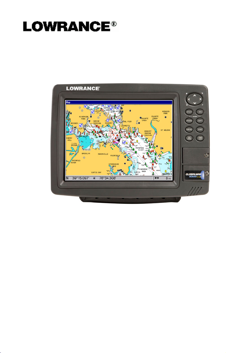
without notice. All screens in this manual are simulated. On the cover:
®
GlobalMap
9300C HD shown.
NMEA 2000
®
Certification Pending.
For free owner's manuals and other information,
visit our web site:
www.lowrance.com
Lowrance Electronics Inc.
12000 E. Skelly Dr.
Tulsa, OK USA 74128-2486
Printed in USA.
Page 3

Table of Contents
Section 1: Read Me First! ......................................................... 1
How Lowrance GPS Works........................................................... 3
Introduction to GPS and WAAS................................................... 4
How to use this manual: typographical conventions .................. 7
Section 2: Installation & Accessories.................................... 9
Preparations .................................................................................. 9
GPS Antenna/Receiver Module .................................................... 9
Power Connections ...................................................................... 10
Powering Your Display Unit ...................................................... 11
Powering a NMEA 2000 Network Bus ...................................... 13
NMEA 2000 Cable Connections ................................................. 14
NMEA 0183 Wiring (Data cable) ............................................... 15
Expanding to a NMEA 2000 Network ....................................... 20
Mounting the Unit: Bracket, In-Dash or Portable.................... 22
MMC or SD Memory Card Installation ..................................... 26
Other Accessories ........................................................................ 27
Face Cover ............................................................................... 28
Cleaning Towel ........................................................................ 28
Section 3: Basic GPS Operations ......................................... 29
Keyboard ...................................................................................... 29
Power/lights on and off ............................................................... 30
Main Menu................................................................................... 30
Pages ............................................................................................ 32
Satellite Status Page............................................................... 32
Navigation Page ...................................................................... 33
Map Page ................................................................................. 36
GPS Quick Reference ............................................................. 41
Find Your Current Position........................................................ 42
Moving Around the Map: Zoom & Cursor Arrow Keys............. 42
Selecting Any Map Item with the Cursor.................................. 43
Searching ..................................................................................... 43
Set a Waypoint ............................................................................ 45
Navigate To a Waypoint ............................................................. 47
Set Man Overboard (MOB) Waypoint........................................ 48
Navigate Back to MOB Waypoint .............................................. 48
Navigate to Cursor Position on Map.......................................... 49
Navigate to a Point of Interest ................................................... 50
Creating and Saving a Trail ....................................................... 51
Displaying a Saved Trail ............................................................ 52
Navigating Trails ........................................................................ 53
Visual Trailing......................................................................... 53
i
Page 4

Navigate a Trail (forward)...................................................... 53
Navigate a Back Trail (backtrack, or reverse) ...................... 55
Transfer Custom Maps and GPS Data Files ............................. 56
Save GPS Data to Hard Drive.................................................... 58
Cancel Navigation ....................................................................... 59
Section 4: Advanced GPS Operations................................. 61
Find Distance to Another Location ............................................ 61
Find Distance From Point to Point ............................................ 61
Icons ............................................................................................. 61
Create Icon on Map ................................................................. 62
Create Icon at Current Position ............................................. 62
Delete an Icon .......................................................................... 62
Navigate to an Icon ................................................................. 63
Routes .......................................................................................... 63
Create and Save a Route ........................................................ 63
Delete a Route ......................................................................... 65
Edit a Route ............................................................................. 66
Navigate a Route ..................................................................... 67
Navigate a Route in Reverse .................................................. 67
Trails ............................................................................................ 68
Delete a Trail ........................................................................... 68
Edit a Trail Name ................................................................... 69
Edit a Trail Color .................................................................... 69
Edit a Trail Pattern................................................................. 69
Utilities ........................................................................................ 70
Alarm Clock ............................................................................. 70
Sun/Moon Rise & Set Calculator............................................ 70
Trip Calculator ........................................................................ 70
Trip Down Timer ..................................................................... 70
Trip Up Timer.......................................................................... 70
Waypoints .................................................................................... 70
Delete a Waypoint ................................................................... 70
Edit a Waypoint....................................................................... 71
Selecting a Waypoint .............................................................. 71
Set a Waypoint by Average Position ...................................... 71
Set a Waypoint by Projecting a Position................................ 72
Set a Waypoint by Entering a Position.................................. 72
Section 5: System & GPS Setup Options ............................ 73
Alarms.......................................................................................... 73
Auto Satellite Search .................................................................. 74
Check MMC Files and Storage Space........................................ 75
Communications Port Configuration ......................................... 75
Configure NMEA......................................................................... 76
ii
Page 5

Coordinate System Selection...................................................... 76
Map Fix ........................................................................................ 78
Customize Page Displays............................................................ 79
GPS Simulator............................................................................. 80
Simulating Trail or Route Navigation ................................... 81
Initialize GPS .............................................................................. 82
Map Auto Zoom ........................................................................... 82
Map Data ..................................................................................... 82
Earth Map Detail .................................................................... 83
Pop-up Map Info ...................................................................... 83
Map Boundaries ...................................................................... 83
Fill Water with White ............................................................. 83
Trackline Extension ................................................................ 83
Presentation Mode .................................................................. 84
Safety Contour......................................................................... 84
Map Overlays (Range Rings; Lat/Long Grid) ........................ 84
Map Datum Selection.................................................................. 85
Map Detail Category Selection................................................... 85
Map Orientation.......................................................................... 86
NauticPath™ USA Marine Charts............................................. 87
Nautical Chart Notes .............................................................. 87
Port Information...................................................................... 88
Tidal Current Information...................................................... 89
Tide Information ..................................................................... 91
Navionics® Charts ....................................................................... 92
To display a Navionics chart: ................................................. 93
Overlay Data ............................................................................... 93
Pop-up Help ................................................................................. 99
Reset Options............................................................................. 100
Screen Contrast and Brightness .............................................. 100
Set Language ............................................................................. 101
Set Local Time ........................................................................... 101
Show WAAS Alarm ................................................................... 102
Software Version Information .................................................. 103
Sounds and Alarm Sound Styles .............................................. 103
Track Smoothing ....................................................................... 104
Trail Options.............................................................................. 105
Delete All Trails .................................................................... 105
Update Trail Options ............................................................ 105
Delete Trail ............................................................................ 106
New Trail ............................................................................... 107
Trail Visible/Invisible and Other Trail Options.................. 107
Transparency (available in some models) ............................... 107
iii
Page 6

Units of Measure ....................................................................... 108
Section 6: Searching............................................................. 109
Find Addresses .......................................................................... 110
Find Any Item Selected by Map Cursor .................................. 112
Find Interstate Highway Exits ................................................ 113
Find Map Places or Points of Interest (POI) ........................... 115
Find Streets or Intersections.................................................... 116
Find a Street .......................................................................... 116
Find an Intersection.............................................................. 118
Find Waypoints ......................................................................... 120
Section 7: NMEA 2000 Device Configuration................. 123
NMEA 2000 Menu..................................................................... 123
Bus Setup................................................................................... 123
Engine & Tank Configuration.................................................. 124
Device Configuration Menu.................................................. 126
Device Information and Device Data ................................... 126
Fuel Management Menu........................................................... 127
Adding Fuel to Tank ............................................................. 128
Engine Operations................................................................. 128
NMEA 2000 Alarms .................................................................. 129
Waypoint Sharing ..................................................................... 130
Backlight Synchronization ....................................................... 130
Configuring EP Sensors............................................................ 130
EP-35 Temperature Configuration ...................................... 130
Advanced Options menu .................................................. 131
EP-10 Fuel Flow Configuration............................................ 132
Advanced Options menu .................................................. 133
EP-15 Fluid Level Configuration ......................................... 134
Advanced Options menu .................................................. 135
Suzuki Engine Interface Configuration............................... 136
Advanced Options menu .................................................. 137
Calibrating EP Sensors............................................................. 138
EP-10 Fuel Flow Calibration................................................ 138
EP-15 Fluid Level Calibration ............................................. 140
Fuel Flow Calibration in a Suzuki Engine Interface.......... 143
Engine Trim Calibration....................................................... 144
Reset Trim Calibration ......................................................... 144
Bennett Trim Tabs Calibration ............................................ 145
Section 8: Supplemental Material ..................................... 147
iv
Page 7

A CAREFUL NAVIGATOR NEVER RELIES ON ONLY ONE METHOD
TO OBTAIN POSITION INFORMATION.
WARNING!
When showing navigation data to a position (waypoint), a GPS unit will show
the shortest, most direct path to the waypoint. It provides navigation data to the
waypoint regardless of obstructions. Therefore, the prudent navigator will not
only take advantage of all available navigation tools when traveling to a waypoint, but will also visually check to make sure a clear, safe path to the waypoint
is always available.
When a GPS unit is used in a vehicle, the vehicle operator is solely responsible for operating the vehicle in a safe manner. Vehicle operators
must maintain full surveillance of all pertinent driving, boating or flying
conditions at all times. An accident or collision resulting in damage to
property, personal injury or death could occur if the operator of a GPSequipped vehicle fails to pay full attention to travel conditions and vehicle operation while the vehicle is in motion.
CAUTION
WARNING!
v
Page 8

Notes
vi
Page 9

Section 1: Read Me First!
How this manual can get you out on the road, fast!
Welcome to the exciting world of GPS satellite navigation! We know
you're anxious to begin finding your way with this space-age technology, but we have a favor to ask. Before you grab the GlobalMap
begin installing it, please give us a moment or two to explain how our
manual can help you get the best performance from your highresolution, high-performance GPS+WAAS chart recorder.
First, we want to thank you for buying a Lowrance GPS unit. Whether
you're a first time user or a professional navigator, you'll discover that
your GlobalMap is easy to use, yet capable of handling demanding
navigation tasks. When you team your unit with our custom mapping
software MapCreate™ 6, you have an incredible combination. No other
consumer GPS mapping system on the market offers so much information and so many features in one package.
Our goal for this book is to get you on the road fast, with a minimum of
fuss. Like you, we'd rather spend more time navigating and less time
reading the manual!
So, we designed our book so that you don't have to read the whole thing
from front to back for the information you want. At the start (or end) of
each segment, we'll tell you what content is coming up next. If it's a
concept you're already familiar with, we'll show you how and where to
skip ahead for the next important topic. We've also made it easy to look
up any tips you may need from time to time. Here's how:
®
and
The manual is organized into 8 sections. This first section is an introduction to Lowrance GPS. It tells you the basics you need to know before you can make the unit look around and tell you where you are.
Section 2 will help you install your unit and the GPS antenna module.
We'll show you how to get the MultiMedia Card (MMC) correctly installed inside the unit. We'll also tell you about some of the available
accessories.
Section 3 covers Basic GPS Operation. It will show you how easy it is to
run the GlobalMap, right out of the box. This section features a onepage GPS Quick Reference. (If you've already jumped ahead and
figured out how to install the unit yourself, and you just can't
wait any longer, turn to the Quick Reference on page 41 and
head for the road with your GPS unit!)
1
Page 10

Section 3 contains short, easy-to-scan GPS lessons that follow one another in chronological order. They're all you'll need to know to find your
way on the water or in the wilderness quickly.
After you've learned the basics (or if you already have some GPS experience), you may want to try out some of the GlobalMap's many advanced navigation features. That brings us to Section 4, Advanced GPS
Operations. This section contains the rest of the unit's GPS command
functions, organized in alphabetical order.
When you come to a GPS menu command on the GlobalMap's screen, you
can look it up in the manual by skimming over the table of contents, just
flipping through Section 3 or scanning through the command portion of
Section 4.
This unit is ready to use right out of the box, but you can fine tune and
customize its operation with dozens of options. We describe how to use
general system options along with GPS options in Section 5, System Setup
and GPS Setup Options. Section 5 is organized in alphabetical order.
In Section 6, we go into more detail on one of the GlobalMap's most remarkable capabilities — Searching. We'll introduce a search example in
the Basic GPS Operation section, but there are so many map items you
can search for, we had to give this function its own section in the manual!
For example, did you know this unit can look up business phone numbers,
functioning as a virtual Yellow Pages? We’ll show you how in Section 6.
In Section 7, we explain how to use the NMEA 2000 network that allows
you to configure, calibrate and monitor devices on a NMEA 2000 network.
Finally, in Section 8, we offer Supplemental Material, including a list of
the GPS datums used, warranties and customer service information.
NOTICE!
The storage and operation temperature range for your unit is from 20 degrees to +167 degrees Fahrenheit (-28 degrees to +75 degrees
Celsius). Extended storage or operation in temperatures higher or
lower than specified will damage the liquid crystal display in your
unit. This type of damage is not covered by the warranty. For more
information, contact the factory's Customer Service Department;
phone numbers are listed on the last page of the manual.
2
Page 11

How Lowrance GPS Works
You'll navigate faster and easier if you understand how the GlobalMap
scans the sky to tell you where you are on the earth — and, where
you're going (But if you already have a working understanding of GPS
receivers and the GPS navigation system, skip on ahead to Section 2,
Installation & Accessories on page 9. If you're new to GPS, read on, and
you can later impress your friends with your new-found knowledge.).
First, think of your unit as a small but powerful computer (But don't
worry — we made it easy to use, so you don't need to be a computer expert to find your way!). The GlobalMap includes a keypad and a screen
with menus so you can tell it what to do. The screen also lets the unit
show your location on a moving map, as well as point the way to your
destination.
This gimbal-mounted GlobalMap uses an external antenna/receiver
module, which makes the whole system work something like your car
radio. But instead of your favorite dance tunes, this receiver tunes in to
a couple of dozen GPS satellites circling the earth (It will also listen in
to the WAAS satellites in orbit, but more about that in the upcoming
segment introducing you to GPS and WAAS.).
Your unit listens to signals from as many satellites as it can "see"
above the horizon, eliminates the weakest signals, then computes its
location in relation to those satellites. Once the GlobalMap figures its
latitude and longitude, it plots that position on the moving map shown
on the screen. The whole process takes place several times a second!
The performance doesn't stop there. Stored in the permanent memory
of each unit is a basic background map of the entire world. We lock it in
here at the factory — you can't change or erase this map.
The background map is suitable for many navigation chores, but for
maximum accuracy and much more detail, you need our optional mapmaking software, MapCreate™ 6 (This complete set of mapping data is
already installed on the GlobalMap 7300 and GlobalMap 9300.). Some
unit features — such as searching for businesses and addresses —
won't work without a custom MapCreate map. There is so much detail
in our background map (and even more in MapCreate) that we'll describe their contents and differences in Section 3, Basic GPS Opera-
tions, on page 29.
Another portion of the GlobalMap's onboard memory is devoted to re-
cording GPS navigation information, which includes waypoints, event
marker icons, trails and routes. This lets you look back the way you came.
3
Page 12

Think of this data storage like the hard drive memory in a computer or a
tape in a cassette tape recorder. You can save several different GPS data
files, erase 'em and record new ones, over and over again. Like any computer file, these GPS Data Files (file format *.usr) can be shared between Lowrance GPS or sonar/GPS units or even personal computers.
This GlobalMap has one more thing in common with a personal computer. Just as computers have a floppy disk drive for storing and exchanging files, the unit has a slot for an MMC (MultiMedia Card) or SD
(Secure Digital) card flash memory card. These solid-state memory devices are about the size of a postage stamp, but can hold data ranging
from 8 MB to 1 GB in size (Compare that to a floppy disk's 1.44 MB capacity!). This unit uses all that MMC space for two key GPS purposes.
First, you can backup your onboard GPS Data Files by copying them to
the MMC. Since the MMC is removable (like a floppy disk or a cassette
tape), you can store these GPS Data Files on a personal computer
equipped with an MMC card reader (Or store them on a pocketful of
MMCs, if you don't have a computer.). Our MapCreate mapping software
can save, edit or create its own GPS Data Files, which can be copied to the
MMC and then loaded from the MMC into the unit's memory (NOTE: No
matter where they come from, GPS Data Files must be loaded from the
MMC into memory before the GlobalMap can use them.).
The other key GPS use for MMCs is storage of special high-detail, custom maps, which you can produce on your computer with our MapCreate software. These MapCreate custom maps contain more detail than
the basic background map. These Custom Map Files (file format
*.lcm) can also be shared between Lowrance GPS or sonar/GPS units
and personal computers.
This unit automatically reads Custom Map Files directly from the
MMC or SD card. To use a custom map, all you need to do is slide an
MMC containing a map into the GlobalMap 7200, GlobalMap 8200 or
GlobalMap 9200.
The GlobalMap 7300, GlobalMap 8300 and GlobalMap 9300 don't read
their mapping data from memory cards. In those units, the full-detail,
ready-to-use maps are already loaded on the unit's hard drives. All you
need to do is use the menus to select what type of mapping data to display. The GlobalMap 7300 and 9300 hard drives contain all the data
from: MapCreate Topo, our NauticPaths™ coastal charts and Fishing
Hot Spots Elite
®
lake fishing maps.
Introduction to GPS and WAAS
Well, now you know the basics of how the unit does its work. You might
be ready to jump ahead to Section 2, Installation & Accessories, on page
4
Page 13
9, so you can mount your GlobalMap and plug in the power. Or you
might want to see how our text formatting makes the manual tutorials
easy to skim. If that's the case, move on to "How to Use This Manual"
on page 7. But, if you want to understand the current state of satellite
navigation, look over this segment describing how GPS and its new
companion WAAS work together to get you where you're going.
The Global Positioning System (GPS) was launched July 17, 1995 by
the United States Department of Defense. It was designed as a 24hour-a-day, 365-days-a-year, all weather global navigation system for
the armed forces of the U.S. and its allies. Civilian use was also available at first, but it was less accurate because the military scrambled
the signal somewhat, using a process called Selective Availability (SA).
GPS proved so useful for civilian navigation the federal government
discontinued SA on May 2, 2000, after the military developed other
methods to deny GPS service to enemy forces. Reliable accuracy for civilian users jumped from 100 meters (330 feet) under SA to the present
level of 10 to 20 meters (about 30 to 60 feet).
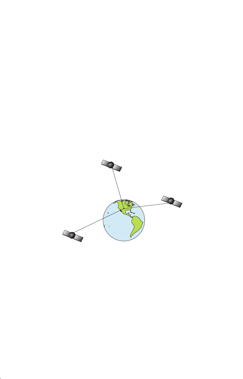
A minimum of three satellites are required to determine a 2D fix.
Twenty-four satellites orbit 10,900 nautical miles above the Earth,
passing overhead twice daily. A series of ground stations (with precisely surveyed locations) controls the satellites and monitors their exact locations in the sky. Each satellite broadcasts a low-power signal
that identifies the satellite and its position above the earth. Three of
these satellites are spares, unused until needed. The rest virtually
guarantee that at least four satellites are in view nearly anywhere on
Earth at all times.
The system requires signal reception from three satellites in order to
determine a position. This is called a 2D fix. It takes four satellites to
determine both position and elevation (your height above sea level —
also called altitude). This is called a 3D fix.
5
Page 14

Remember, the unit must have a clear view of the satellites in order to
receive their signals. Unlike radio or television signals, GPS works at
very high frequencies. These signals can be easily blocked by trees,
buildings, an automobile roof, even your body.
Like most GPS receivers, this unit doesn’t have a compass or any other
navigation aid built inside. It relies solely on the signals from the satellites to calculate a position. Speed, direction of travel, and distance are
all calculated from position information. Therefore, in order for the
GlobalMap to determine direction of travel, you must be moving and
the faster, the better. This is not to say that it won’t work at walking or
trolling speeds — it will. There will simply be more "wandering" of the
data shown on the display.
GPS is plenty accurate for route navigation, but the U.S. Federal Aviation Administration has special needs for aircraft traffic control that go
beyond basic GPS. The FAA has a program to boost GPS performance
even further with its Wide Area Augmentation System, or WAAS. This
GPS add-on will include a time control element that will help airliners
fly closer together while avoiding collisions. In addition to carefully
spacing airplanes along travel corridors, WAAS will eventually make
instrument landings and takeoffs more accurate as it replaces existing
aviation navigation systems.
Non-aviators can use WAAS signals to make their GPS navigation even
more accurate. Your unit receives both GPS and WAAS signals. However, WAAS has some limits you should know about.
WAAS can boost the accuracy of land GPS navigation, but the system
is designed for aircraft. The satellites are in a fixed orbit around the
Equator, so they appear very low in the sky to someone on the ground
in North America. Aircraft and vessels on open water can get consistently good WAAS reception, but terrain, foliage or even large man-made
structures frequently block the WAAS signal from ground receivers.
You'll find that using your GPS receiver is both easy and amazingly
accurate. It’s easily the most accurate method of electronic navigation
available to the general public today. Remember, however, that this
receiver is only a tool. Always have another method of navigation available, such as a map or chart and a compass.
Also remember that this unit will always show navigation information
in the shortest line from your present position to a waypoint, regardless
of terrain! It only calculates position, it can’t know what’s between you
and your destination, for example. It’s up to you to safely navigate
around obstacles, no matter how you’re using this product.
6
Page 15

How to use this manual: typographical conventions
Many instructions are listed as numbered steps. The keypad and arrow
"keystrokes" appear as boldface type. So, if you're in a real hurry (or
just need a reminder), you can skim the instructions and pick out what
menu command to use by finding the boldface command text. The following paragraphs explain how to interpret the text formatting for
those commands and other instructions:
Arrow Keys
The arrow keys control the movement of dotted cross-hair lines on your
mapping screen called the cursor. The arrow keys help you move
around the menus so you can execute different commands. They are
represented by symbols like these, which denote the down arrow key,
the up arrow, the left arrow and the right arrow:
Keyboard
The other keys perform a variety of functions. When the text refers to a
key to press, the key is shown in bold, sans serif type. For example, the
"Enter/Icons" key is shown as
MENU.
ENT and the "Menu" key is shown as
Menu Commands
A menu command or a menu option will appear in small capital letters,
in a bold sans serif type like this:
ROUTE PLANNING. These indicate that
you are to select this command or option from a menu or take an action
of some kind with the menu item. Text that you may need to enter or
file names you need to select are show in italic type, such as trail name.
↓ ↑ ← →.
Instructions = Menu Sequences
Most functions you perform with this unit are described as a sequence
of key strokes and selecting menu commands. We've written them in a
condensed manner for quick and easy reading.
For example, instructions for navigating a trail would look like this:
1. From the Map Page, press
2. Press
↓ to Trail 1|ENT|→|↓ to NAVIGATE|ENT.
MENU|MENU|↓ to MY TRAILS|ENT.
3. You are asked to wait while it converts the trail into a route.
4. The wait message disappears and the GlobalMap begins
showing navigation information along the trail. Now, begin
moving and follow your GlobalMap.
Translated into complete English, step 1 above would mean: "Start on
the Map Page. Press the Menu key twice. Next, repeatedly press (or
7
Page 16

press and hold) the down arrow key to scroll down the menu and select
(highlight) the My Trails menu command. Finally, press the Enter key."
Step 2 would mean: "Press the down arrow key repeatedly to scroll to
the trail named Trail 1, and press Enter. Next, press the right arrow
key and then the down arrow key to highlight the Navigate command,
then press Enter."
NOTE:
There are slight differences in menu structure among the GlobalMap models covered in this manual. The differences are minimal,
but some of the screenshots in this manual may not perfectly match
some of your unit's menus.
8
Page 17
Section 2:
Installation & Accessories
Preparations
You can install the GPS system in some other order if you prefer, but
we recommend this installation sequence:
Caution:
You should read over this entire installation section before drilling any holes in your vehicle or vessel!
1. Determine the approximate location for the GPS unit, so you can
plan how and where to route the cables for the antenna and power.
This will help you make sure you have enough cable length for the desired configuration.
2. Determine the approximate location for the GPS antenna module
and its cable route.
3. Determine the location of your battery or other power connection,
along with the power cable route.
4. Install the GPS antenna and route the antenna cable to the GPS
unit.
5. Install the power cable and route it to the GPS unit.
6. Mount the GPS unit.
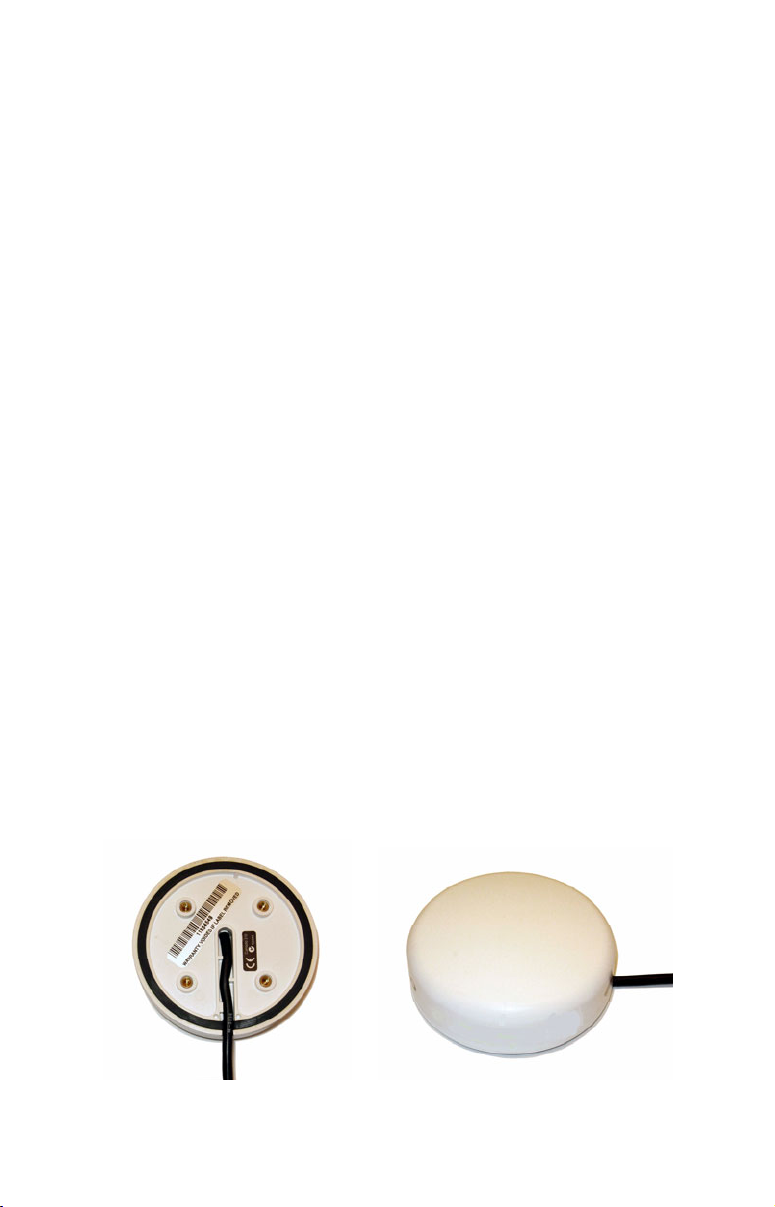
GPS Antenna/Receiver Module
The unit packages covered in this manual include the LGC-3000 GPS
module. This device contains the unit's external antenna and receiver
for GPS and WAAS signals. The antenna/receiver module comes with a
15-foot extension cable. This module can be mounted on a flat surface
or optional pole, or an optional magnet is available for temporary
mounting on any ferrous surface.
LGC-3000 Module, bottom view (left) and top view (right).
9
Page 18
You need to select an antenna installation location that has a clear, unobstructed view of the sky. After the module is installed, connect it to the
unit. The LGC-3000 can communicate with your GPS unit either directly
(using the supplied extension cable) or through a NMEA 2000
®
network.
NOTE:
See the module’s instruction sheet, publication part number 9880154-651, for complete installation instructions.
In an automobile, you may achieve good results by simply placing the
external antenna on the top of the dash, at the base of the windshield. A
piece of the rubber non-skid shelf liner material available in recreational
vehicle supply stores will help hold the antenna in place. This may not
work well if you have a cab-over design pickup truck camper or motor
home. If dashboard reception is poor, simply relocate the antenna module
elsewhere on the vehicle for a clearer view of the sky.
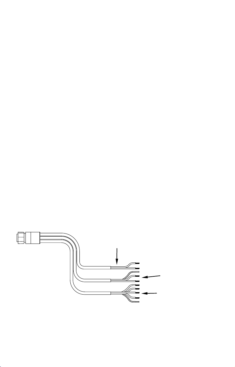
Power Connections
Your unit comes with a power/data cable that splits into three branches,
each with several exposed wires.
The thicker two-wire cable (red and black) is the power supply for your
display unit. This cable has no label.
The branch with three wires (red, black and shield) is the power cable for
a NMEA 2000 network. It is labeled "NMEA 2000 POWER."
The branch with 5 wires (blue, yellow, orange, green and shield) is a data
cable, labeled "RS-232 COMM." It supports two serial communication
ports. These allow your unit to exchange NMEA 0183 data with another
device, such as an autopilot, DSC marine radio or computer.
Display unit power wires:
red and black
To unit
NMEA 2000 power wires:
red, black and shield
Data cable wires: blue,
yellow, orange, green
The Power/Data cable for this unit.
and shield
10
Page 19

NOTE:
There are two basic power connection options, which are shown in the
following two diagrams. Read the following instructions carefully
to determine which power connection applies to your unit. Depending on your configuration, you may not use all of these wires.
Caution:
All of the wires in the power/data cable have bare ends for easier installation. The bare ends on any unused wires could cause
an electrical short if left exposed. To prevent this, you should
cover the individual wire ends – either by capping them with
wire nuts, wrapping them with electrical tape or both. (You
should cut off the bare wire before taping off the ends.)
Powering Your Display Unit
The display unit works from a 12-volt DC battery system. Attach the
display power cable (with provided 3-amp fuse) to an accessory switch
or power bus. If this results in electrical interference, connect direct to
a battery but install an in-line switch on the cable.
Caution:
We strongly recommend that you shut off the power supply to the
power cable when the unit is not in use, especially in saltwater environments. When the unit is turned off but still connected to a
power supply, electrolysis can occur in the power cable plug. This
may result in corrosion of the plug body along with the electrical
contacts in the cable and the unit's power socket. Risk of electrolysis corrosion is even greater when the cable is unplugged from the
unit, but still connected to a power source.
We recommend you connect the power cable to the auxiliary power
switch included in most boat designs. If that results in electrical
interference, or if such a switch is not available, we recommend
connecting direct to the battery and installing an in-line switch.
This will let you shut off power to the power cable when the unit is
not in use. When you are not using the unit, you should always
shut off power to the power cable, especially when the power cable
is disconnected from the unit.
WARNING:
This product must be independently fused with the enclosed 3-amp fuse (or equivalent), even if you connect to
a fused accessory or power bus.
If a malfunction happens inside the unit, extensive damage can
occur if the enclosed fuse is not used. As with all electrical devices,
11
Page 20
this unit could be damaged to a point that it is irreparable and
p
could even cause harm to the user when not properly fused.
Failure to use a 3-amp fuse will void your warranty.
If possible, keep the power cable away from other boat wiring, especially
the engine's wires. This will provide the best isolation from electrical
noise. If the cable is not long enough, splice #18 gauge wire onto it.
The display power cable has two wires, red and black. Red is the positive
(+) lead, black is negative (–) or ground. Make sure to attach the in-line
fuse holder to the red lead as close to the power source as possible.
For example, if you have to extend the power cable to the power bus or
battery, attach one end of the fuse holder directly to the power bus or
battery. This will protect both the unit and the power cable in the event
of a short.
This unit has reverse polarity protection. No damage will occur if the
power wires are reversed. However, the unit will not work until the
wires are attached correctly.
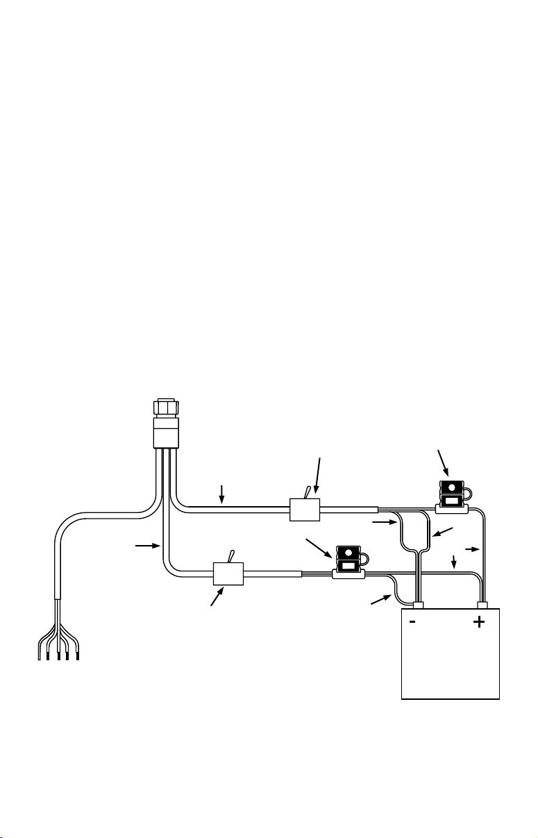
Power Diagram A
To unit
NMEA 2000
Power Cable
Display Unit
Power Cable
Recommended
display unit
ower-off switch
Data Cable
Use this method if you are powering the display unit and a GPS mod-
ule or the display unit and a NMEA 2000 network.
3-amp fuse
Mandatory
network
power-off
switch
Shield
3-amp fuse
Black
Red
Black
12 volt DC
power source
12
Page 21
The network and any NMEA 2000 devices, including the GPS
module, will not operate
unless the NMEA 2000 Power Cable is
connected to power. The NMEA 2000 power cable must be connected
to power even if your only NMEA 2000 device is the GPS module and it
is connected to the display unit's Network socket. (However, never con-
nect multiple power sources to a NMEA 2000 network. If you have
a network that is already powered, see diagram B.)
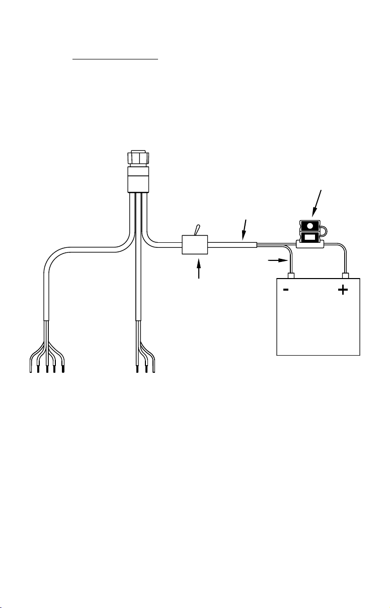
Power Diagram B
To unit
Display Unit
Power Cable
All unused Data
or NMEA 2000
power wires
should be
capped with wire
nuts and electrical tape to prevent shorts.
Data Cable
Use this method if you are only powering your display unit and are not
powering a NMEA 2000 network or any NMEA 2000 accessory device,
NMEA 2000 Power Cable
Recommended
power off switch
including a GPS module.
Black wire
Red wire with
3-amp fuse
12 volt DC
power source
The method in diagram B is also used when your display unit is connected
to a NMEA 2000 network that is already connected to power (Never connect multiple power sources to a NMEA 2000 network.)
Powering a NMEA 2000 Network Bus
A NMEA 2000 bus must be connected to a power source to operate. NMEA
2000 devices, including GPS modules, draw their power from the network bus.
If you have a pre-existing NMEA 2000 network installation, it may already be
connected to another power source. If you are not sure about a network's power
status, consult the boat manufacturer or dealer. If your NMEA 2000 bus is already powered, you do not need to connect the NMEA 2000 Power cable and
13
Page 22

use the method shown in Power Diagram B above. Never attach two power
sources to a single NMEA 2000 bus.
If you do need to power your NMEA 2000 bus, attach the NMEA 2000 Power
cable to an accessory switch as indicated in power diagram A. The NMEA
2000 Power cable's red wire should be attached (with provided 3-amp fuse) to
the positive (+) terminal. The NMEA 2000 Power cable's black and shield
wires should both be attached to the negative (–) terminal.
WARNING:
The NMEA 2000 network bus is always on and constantly
drawing power. You must connect NMEA power to a
switched power source so you can turn off the network
when not in use. Failure to connect to and use a power
switch will drain your boat battery, which could stop
your boat's operation.
NMEA 2000 Cable Connections
NMEA 2000 is a new bus network specifically designed for boats. This
is a young industry standard and, at the time of printing, some boats
being built now have a NMEA 2000 bus installed. Over the next few
years, however, NMEA 2000 will become much more common. To help
you get the most out of this technology, your Lowrance unit is designed
to work with a NMEA 2000 network.
Connecting to a NMEA 2000 Network
A network bus is an installed and operational network cable (backbone)
running the length of your boat, already connected to a power supply
and properly terminated. Such a bus provides network connection
nodes at various locations around your boat.
The NMEA 2000 network is similar to the telephone wiring in a house.
If you pick up a phone in your living room, you can hear someone talking into the phone in the bedroom.
Lowrance and LEI provide all the cables you will need to create a
NMEA 2000 network. Lowrance provides T connectors and extension
cables so you can add devices along the backbone wherever you want.
Once you have a working network, every sensor added will come with
its own T connector for easy expansion.
The simplest NMEA 2000 network is a GPS or sonar/GPS display unit
with the LGC-3000, one double-T connector, two 120 ohm terminators
and any extension cables needed to connect them.
14
Page 23
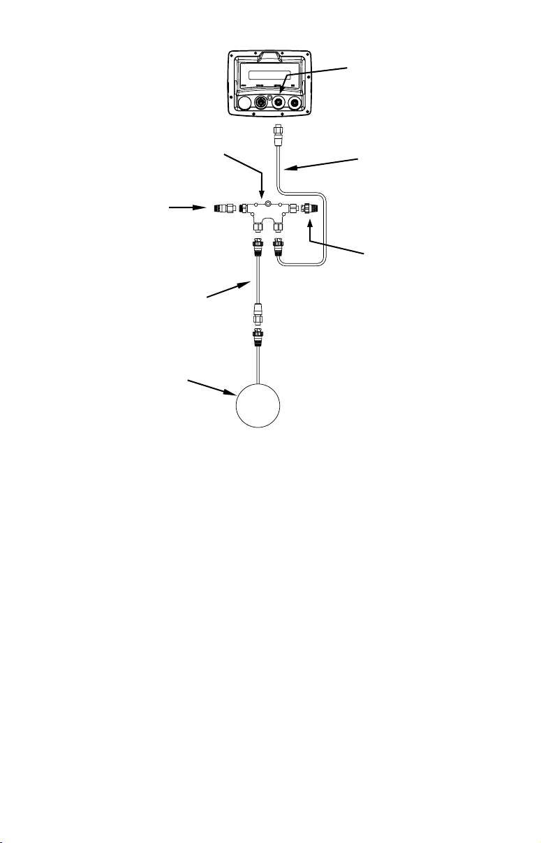
Network port
on display unit
Double T
Connector
120-ohm
terminator
Extension cable
LGC-3000
Extension cable
120-ohm
terminator
LGC-3000 and display unit as an expandable NMEA 2000 network.
The diagram above has a double T connector with two 120-ohm terminators — one at each end of the connector. It is easy to expand this network
by removing a terminator from one end of the double T connector, then
inserting a new T connector or extension cable between the double T connector and terminator (See the NMEA 200 network general information
document that came with your unit for more information).
NMEA 0183 Wiring (Data cable)
To exchange NMEA 0183 data, this unit has two NMEA 0183 version
2.0 communication ports. Serial Communications Port one (Com1) and
Serial Communications Port two (Com2) can be used to transmit or receive NMEA format GPS data.
The five wires for the Serial Communications Ports are combined with
the Display Unit Power cable and NMEA 2000 Power cable to form the
power/data cable (shown earlier). Com1 uses the yellow wire to transmit, the orange wire to receive and the shield wire for signal ground.
Com2 uses the blue wire to transmit, the green wire to receive and the
shield wire for signal ground.
15
Page 24
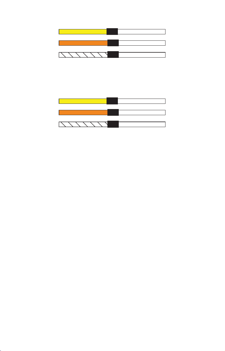
Y
ellow (Transmit)
Receive
Com-1
To Unit
Com-2
To Unit
Orange (Receive)
Shield (Ground)
Com-1 wiring to exchange information
with another device.
Blue (Transmit)
Green (Receive)
Shield (Ground)
Com-2 wiring to exchange information
with another device.
Transmit
Ground
Receive
Transmit
Ground
To Other
Device
To Other
Device
16
Page 25
(
r
Ethernet
(for later
expansion)
Power/Data
NMEA 0183
Data cable
five wires)
NMEA 2000
Power cable
120-ohm
female
terminato
Display unit
power cable
Network
Double T-connector
120-ohm
male
terminator
Extension cables
LGC 3000
GPS
Module
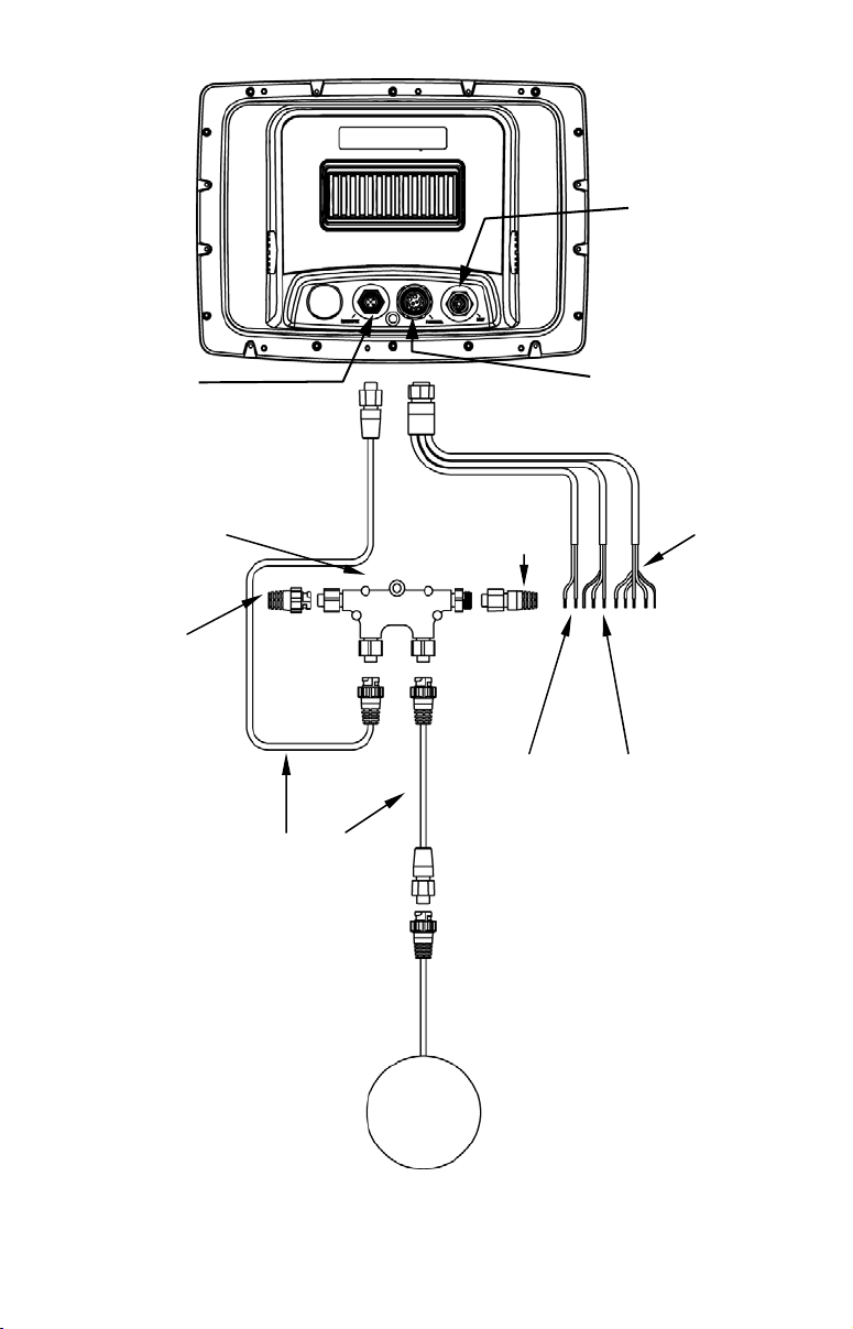
Cable connections, GlobalMap 7200 and GlobalMap 7300.
17
Page 26
Ethernet
(
)
(for later
expansion)
Power/Data
Double T-connector
120-ohm
male
terminator
Extension cables
120-ohm female
terminator
Display unit
power cable
Network
NMEA 0183
Data cable
five wires
NMEA 2000
Power cable
LGC-3000
GPS
Module
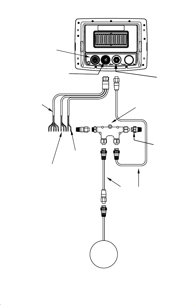
Cable connections, GlobalMap 8200 and GlobalMap 8300
18
Page 27
(
Ethernet
(for later
expansion)
Power/Data
NMEA 0183
Data cable
five wires)
NMEA 2000
Power cable
Network
Double T-connector
120-ohm female
terminator
120-ohm
male
terminator
Display unit
power cable
Extension cables
LGC-3000
GPS
Module
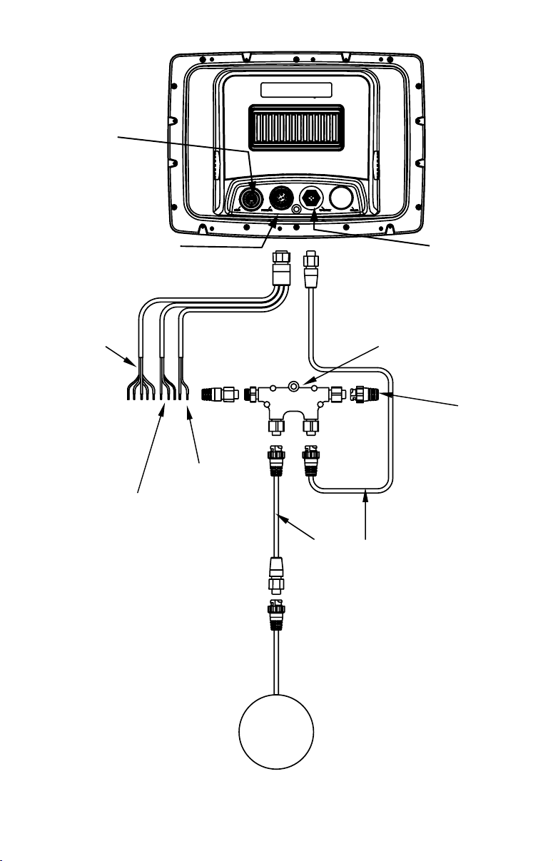
Cable connections, GlobalMap 9200 and GlobalMap 9300.
19
Page 28
Expanding to a NMEA 2000 Network
A network bus is an installed and operational network cable (backbone)
running the length of your boat, already connected to a power supply and
properly terminated. Such a bus provides network connection nodes at
various locations around your boat.
The NMEA 2000 network is similar to the telephone wiring in a house.
If you pick up a phone in your living room, you can hear someone talking into the phone in the bedroom.
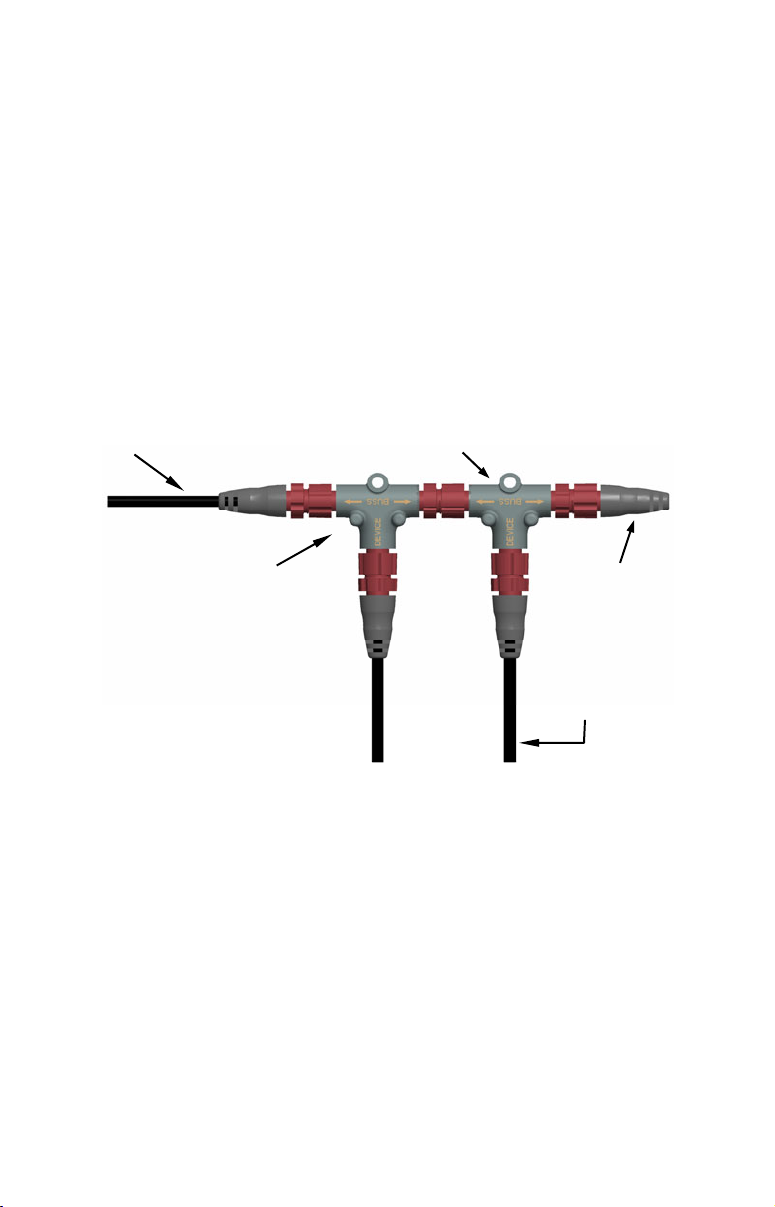
Network Nodes
A network bus is built of network nodes spread along a backbone. Network
nodes are made by fitting T-shaped connectors into the backbone (using the
sockets on the sides), and attaching any network device to the bottom of the "T."
Using our telephone example, the T connectors on the backbone are similar
to telephone jacks spread throughout a house. To pick up a phone and be
able to hear a conversation from another phone in the house, both phones
must be connected to the main phone line. In similar fashion, only sensors
and display units plugged into the NMEA network can share information.
The network backbone is like the phone wiring that runs throughout a
home. It connects the network nodes, allowing them to communicate across
the network. Connections found in the middle of the bus could have T connectors or backbone network cable plugged into one or both sides. Connections at the end of a network will have the backbone cable or a T connector
plugged into one side and a terminator plugged into the other, as shown in
the following figure.
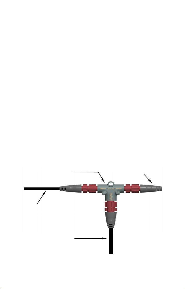
T connector
Terminator at
the very end
of the bus
Backbone cable
(to rest of bus)
Cable from
sensor or
display unit
NMEA 2000 network node located at the end of a NMEA 2000 bus.
20
Page 29
NOTE:
If you have a double T Connector on your network that is not attached to a device, you must cap the unused connector with a
NMEA 2000 cap. This will protect the pin connectors from corrosion. The NMEA 2000 cap looks like a terminator, but has "Cap"
stamped into the connector housing.
Adding a Network Node
You can add a node to any existing connection, anywhere along the network backbone. This connection could be between a T connector and a
terminator, between two T connectors, between a T connector and a
backbone extension cable or between two extension cables. Wherever
you want to add the new node, separate the sockets of the existing connection and install the T connector between them.
Add T-shaped connector to
Backbone cable
Existing
network node
add new device to bus.
Re-attach
terminator at
end of bus.
LowranceNET device
connects to new
T connector.
Add a new device to a NMEA 2000 bus by attaching a T connector be-
tween two T connectors, between a T connector and the end termina-
tor, or between two backbone extension cables.
If you want to add a node at the end of the backbone (network bus) remove the terminator from the last connector, like the figure above. Install the new T connector and attach the terminator to the side of the
connector.
Additional Network Information
Further instructions on creating or expanding a network are illustrated in
the NMEA 2000 network setup booklet, part number 988-0154-173, which
came packed with manual.
21
Page 30
NOTE:
You do not need a Bus Adapter Cable with this unit if you use an
approved Devicenet NMEA 2000 connector. Approved Devicenet
NMEA 2000 connectors work with Lowrance red connector display units and components, so no adapter cables are needed.
Mounting the Unit: Bracket, In-Dash or Portable
You can install the GlobalMap on the top of a dash with the supplied
gimbal bracket. The GlobalMap 7200 and GlobalMap 7300 can also be
installed in the dash or mounted on a portable power supply.
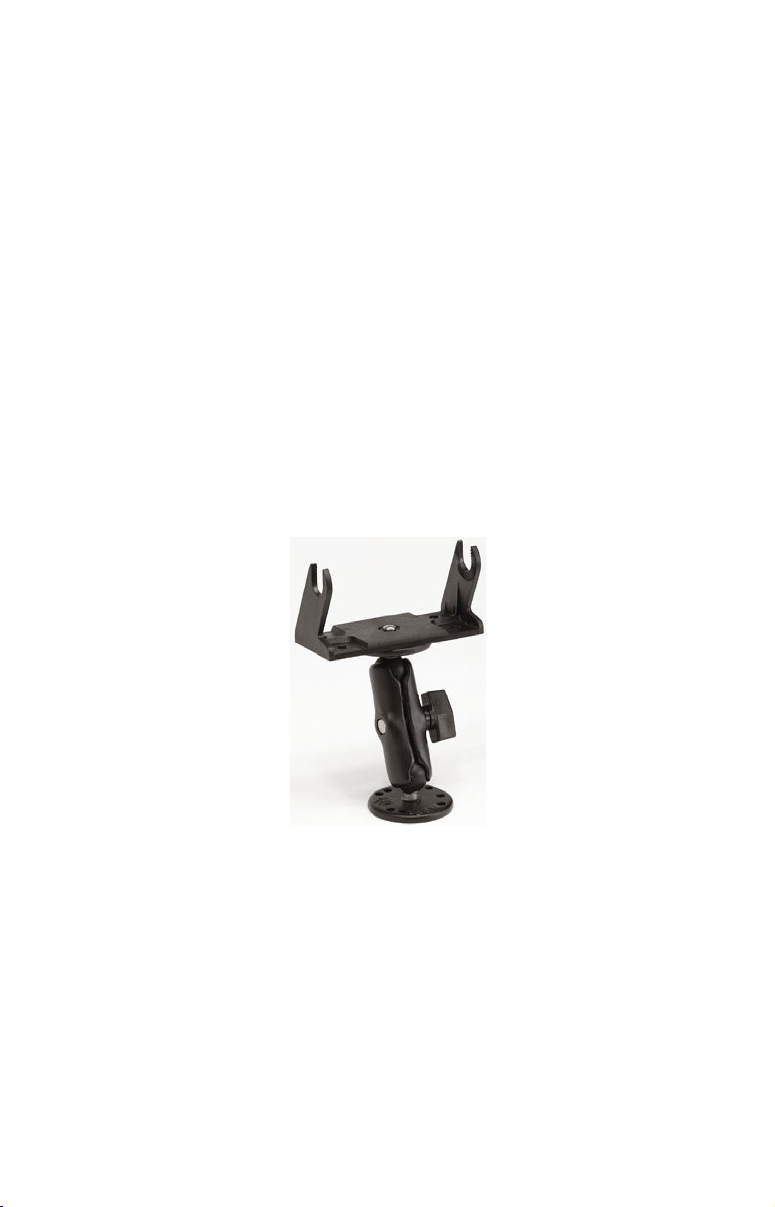
If you use the supplied bracket, you may be interested in the optional R-A-
®
bracket mounting system. This converts the unit's gimbal bracket to a
M
swivel mount, which can be used on the dash or overhead mounting positions. Installation instructions are supplied with the R-A-M mounting
kits. R-A-M offers permanent mounts and temporary mounts suitable for
many vehicle types. See your Eagle dealer or visit the LEI web site
(
www.lei-extras.com) for the latest options; accessory ordering information
is on the inside back cover of this manual. For a complete look at the
many mounting options, visit the RAM web site at
www.ram-mount.com.
Optional R-A-M mounting system.
Bracket Installation
Mount the GlobalMap in any convenient location, provided there is clearance behind the unit when it's tilted for the best viewing angle. You should
also make sure there is enough room behind the GlobalMap to attach the
power and GPS antenna/receiver module cables (Drawings beginning on
the next page shows the dimensions of the gimbal-mounted GlobalMaps.).
Holes in the bracket's base allow wood screw or through-bolt mounting.
You may need to place a piece of plywood on the backside of thin fiberglass panels to reinforce the panel and secure the mounting hardware.
22
Page 31
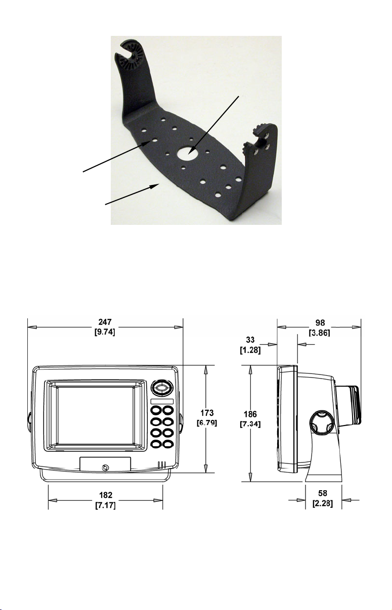
Cable hole
Screw
mounting
hole
Front
Install the gimbal bracket. Place the bracket so the arms slope toward
the front of your unit.
Once a location is determined, use the bracket as a template and mark
the mounting holes and the hole for the cables. Drill a 1-inch (25.4 mm)
hole in the dash for the power, transducer and antenna cables. Screw
the bracket to the mounting surface.
Millimeter
[Inch]
Front view (left) and side view (right) showing dimensions of the
GlobalMap 7200 and GlobalMap 7300 mounted on gimbal brackets.
23
Page 32
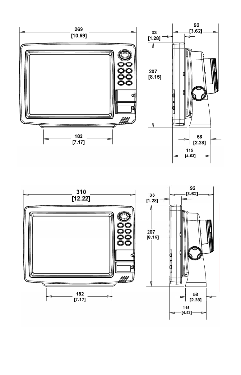
Millimeter
[Inch]
Front view (left) and side view (right) showing dimensions of the
GlobalMap 8200c and GlobalMap 8300CHD mounted on gimbal brackets.
Millimeter
[Inch]
Front view (left) and side view (right) showing dimensions of the
GlobalMap 9200 and GlobalMap 9300 mounted on gimbal brackets.
24
Page 33
To pass all connectors through the 1" hole, first pass the antenna connector up through the hole from under the dash. Next, pass the power
cable's bare-wire end down though the hole from the top.
If you wish, you can fill in the hole around the cables with a good marine caulking compound. No matter what type of installation you prefer, be sure to leave enough slack in the cables to allow tilting or swiveling the unit.
Attach the unit to the gimbal bracket using the supplied gimbal knobs
and washers. Attach the cables and the unit is ready to use.
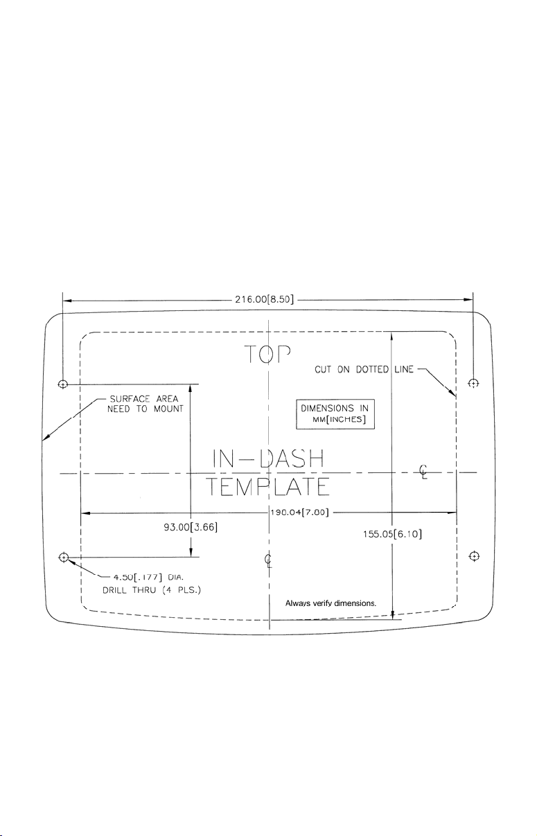
In-Dash Installation
You can mount the GlobalMap 7200 and GlobalMap 7300 in the dash
with an optional FM-3 In-Dash Adapter Kit. The kit includes mounting
hardware and a template for cutting the hole.
In-dash mounting template for the GlobalMap 7200 and GlobalMap
7300, showing dimensions. The figure above is not printed to scale.
Portable Installation
Like many Lowrance products, the GlobalMap 7200 and GlobalMap
7300 are capable of portable operation by using an optional portable
power pack. The power pack and the magnet-equipped antenna module
expand the uses for your GPS unit. The portable power pack makes it
25
Page 34
easy to transfer your unit from a boat to a car, recreational vehicle, air-
r
plane or other vehicle without drilling and mounting a second bracket.
You can use your unit in your own car or boat, then take it along when
riding in a friend's vehicle that's not equipped with GPS.
The portable power pack includes a sealed, rechargeable battery.
MMC or SD Memory Card Installation
Your unit uses MultiMedia Cards to store information, such as custom maps,
waypoints, trails and other GPS data. The unit can also use Secure Digital
Cards (SD card) to store data. These units can use up to two cards; an MMC
and an SD card can be used at the same time.
NOTE:
Throughout this manual, we will use the term MMC, but just remember your unit can use an MMC or SD card to store data.
Both of these solid-state flash memory devices are about the size of a postage
stamp. A SD card is slightly thicker than a MMC. MMCs are available in
storage capacities of 8 MB, 16 MB, 32 MB, 64 MB and higher. SD cards are
available in capacities of 8 MB, 16 MB, 32 MB, 64 MB, 128 MB, 256 MB, 1 GB
and higher.
Additional MMC cards are available from LEI Extras; see ordering information inside the back cover of this manual. MMCs and SD cards are also
available at many camera and consumer electronics stores.
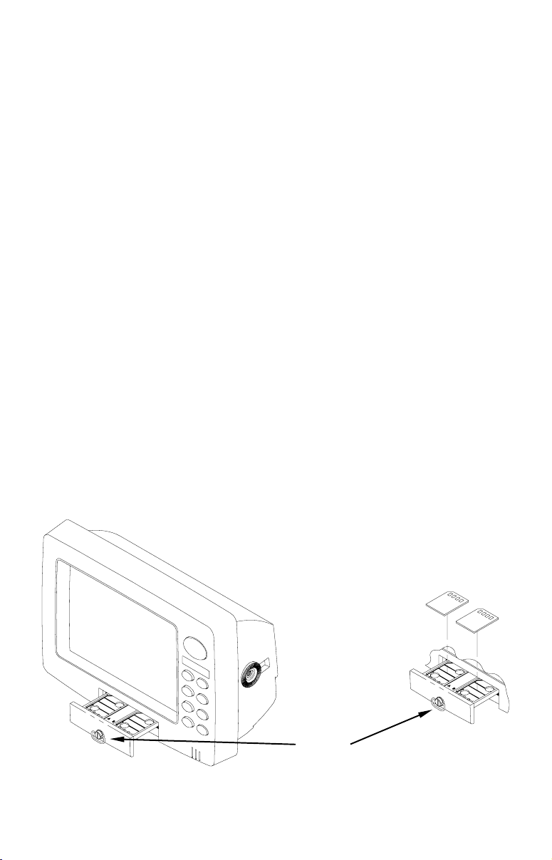
In the GlobalMap 7200 and GlobalMap 7300, the MMC drawer is located
on the front of the case. To install an MMC, twist the drawer retainer
counter-clockwise and pull. The drawer will come out of the unit. Place the
MMC in the drawer face down (see following figures).
Insert cards face down
Drawer
retaine
Memory card drawer on the GlobalMap 7200 and GlobalMap 7300.
26
Page 35
Slide the drawer back into the unit and twist the retainer clockwise. The
MMC is now ready for use.
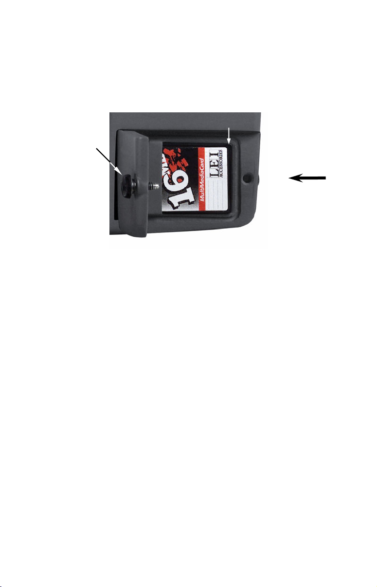
In the GlobalMap 9200 and GlobalMap 9300, the two MMC slots are located
in compartments on the front of the case. The water-proof compartment doors
are located at the lower right corner. The following figure shows a close-up of
one compartment with the door opened.
MMC groove for card removal
Thumb
screw
Insert card face up,
this way
Memory card compartment with a 16 MB MMC card installed.
To remove an MMC or SD Card
1. Open the card compartment door by unscrewing the thumb screw. The
screw should only be finger tight. If it was over-tightened, use a thumbnail, a
coin or a screwdriver to open the door.
2. Use the ball of your finger or thumb and press down in the center of the
card, then drag the MMC from the slot. Or, use a thumbnail or fingernail to
grab the groove in the bottom of the MMC and drag it out. See the figure
above for the groove location.
To add an MMC or SD Card
1. Open the card compartment door.
2. Grasp the bottom of the MMC and push the top of the card into the
slot. Once the card is started, press down in the center of the card with
the ball of your finger or thumb and push the card all the way to the
left, until it is firmly seated in the slot.
3. Close the compartment door and fasten the thumbscrew finger tight.
Other Accessories
Other accessories include MMC cards, MMC card readers and MapCreate™ custom mapping software for your computer. MMC card readers are available in USB versions.
If these accessories are not available from your dealer, see the accessory ordering information on the inside back cover of this manual.
27
Page 36

MapCreate™ 6 CD-ROM, left; MMC card reader for USB ports, right.
Now that you have your GlobalMap installed, move on to Section 3, Basic GPS Operations. There, we'll present a series of step-by-step tutori-
als to teach you the basics of GPS navigation.
Face Cover
Your unit comes with a white protective cover that snaps on and off the
front of the unit. This cover is intended for use when your unit and the
vehicle it's mounted in are idle.
WARNING:
When the unit is mounted in an unprotected area, such as
an open boat cockpit, the protective face cover must be
removed when the vehicle is moving at high speed. This
includes towing a boat on a trailer at highway speeds. Otherwise, windblast can pop off the cover.
Cleaning Towel
A lint-free microfiber towel is included for cleaning the unit’s screen.
The towel is highly effective in clearing away water spots, smudges and
finger prints. Just wipe the screen with the dry towel — it's not necessary to moisten the towel with water. If the screen is badly soiled, you
may use water or common window or lens cleaners. However, DO NOT
use polishing compounds or any other abrasive product.
If you lose the towel or wear it out, you can replace it with a similar
microfiber cloth. These are often available where shop towels or automobile cleaning towels are sold.
Caution:
Cleaning fabrics other than the microfiber towel type may scratch
the screen. Polishing compounds or other abrasive cleaners will
scratch the screen. Damage caused by incorrect cleaning is not covered by the warranty. You may wash the towel if it becomes soiled
or loses its effectiveness, but do not use fabric softener. Fabric softener will ruin the towel’s cleaning capability.
28
Page 37

Section 3:
Basic GPS Operations
This section addresses the unit's most basic GPS operations. The tutorials presented in Sec. 3 follow a chronological order. Sec. 4, Advanced
GPS Operations, will discuss other more advanced functions and utilities. Material in Sec. 4 is arranged in alphabetical order.
Before you turn on the unit and find where you are, it's a good idea to
learn about the different keys, the four Page screens and how they all
work together. BUT, if you just can't wait to get outside, turn to the
one-page Quick Reference on page 41.
NOTE:
There are slight differences in menu structure among the GlobalMap models covered in this manual. The differences are minimal,
but some of the screenshots in this manual may not perfectly match
some of your unit's menus.
Keyboard
4
8
2
3
5
MMC drawers
GlobalMap 9300CHD GPS unit, front view, showing screen,
keyboard and MMC drawers.
29
9
9
7
7
6
6
1
1
Page 38

1. PWR/LIGHT (Power & Light) – The PWR key turns the unit on and
off and activates the backlight.
2. PAGES – Pressing this and the
← → arrow keys (4) switches the
unit between the three different page screens (Satellite Status Page,
Navigation Page, Map Page and Radar Page). Each page represents
one of the unit's major operation modes.
3. MENU – Press this key to show the menus and submenus, which
allow you to select a command or adjust a feature. This also accesses
search functions for streets, intersections, addresses and highway exits.
4. ARROW KEYS – These keys are used to navigate through the
menus, make menu selections, move the map cursor and enter data.
5. ENT/ICONS (Enter & Icons) – This key allows you to save data, accept values or execute menu commands. It is also used to create event
marker icons.
6. EXIT – The Exit key lets you return to the previous screen, clear
data or close a menu.
7. WPT – (Waypoint) The Waypoint key is used to save and recall waypoints, search for waypoints and access the waypoint list. It also
launches the Point-of-Interest (POI) search menus and is involved in
some navigation functions.
8. ZOUT – (Zoom Out) – This key lets you zoom the screen out. On the
Map Page, this lets you see a larger geographic area on the map. Less
detail is seen as you zoom out.
9. ZIN – (Zoom In) – This key lets you zoom the screen in. On the Map
Page, zooming in lets you see more detail in a smaller geographic area
on the map.
Power/lights on and off
To turn on the unit, press PWR. As the unit powers up, the Map Page is
displayed first (To switch to another page, press
Name|
To turn on the backlight, press
EXIT.).
PWR again. The unit has three back-
light levels to select from. Repeatedly pressing
the backlight settings and turn off the backlight.
Turn off the unit by pressing and holding the
PAGES|← or → to Page
PWR will cycle through
PWR key for 3 seconds.
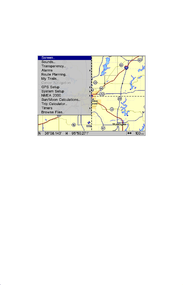
Main Menu
The GlobalMap has a Main Menu, which contains some function commands and some setup option commands. The tutorial lessons in this
section will deal only with functions, the basic commands that make
the unit do something. The unit will work fine for these lessons right
30
Page 39
out of the box with the factory default settings. But, if you want to
learn about the various options, see Sec. 5, System Setup and GPS
Setup Options.
You can access the Main Menu from any of the three Page screens by
pressing
display, press
MENU|MENU. To clear the menu screen and return to the page
EXIT.
Main Menu.
The Main Menu commands and their functions are:
Screen command: changes the contrast or brightness of the screen.
Sounds command: enables or disables the sounds for key strokes and
alarms and sets the alarm style.
Transparency command: adjusts the level of transparency for menus.
Alarms command: turns GPS alarms on or off and changes alarm
thresholds.
Route Planning command: used to plan, view or navigate a route.
My Trails command: shows, hides, creates and deletes plot trails. Also
used to navigate or backtrack a trail.
Cancel Navigation command: turns off the various navigation commands. Used to stop navigating after you have reached your destination waypoint, Point of Interest or map cursor location; or after you
reach the end of a route or trail.
GPS Setup command: sets various GPS receiver options.
System Setup command: sets general configuration options.
Sun/Moon Calculations command: finds the rising and setting time
of the sun and the moon.
31
Page 40
Trip Calculator command: shows trip status and statistics.
Timers command: controls the up timer, down timer and alarm clock
settings.
Browse Files command: this allows you to view the installed MMC card
and the files it contains.
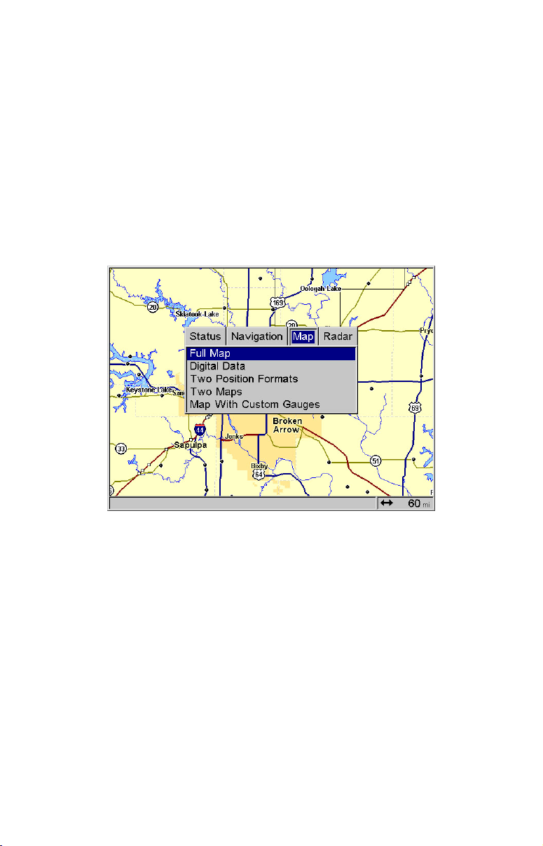
Pages
The unit has four Page displays that represent the four major operating
modes. They are the Satellite Status Page, the Navigation Page, the Map
Page and Radar Page (for more information on Radar see additional materials). They are accessed by pressing the
to select a Page (Clear the Pages Menu by pressing
PAGES key, then using → or ←
EXIT.).
Pages Menu showing some Map display options.
Satellite Status Page
The Satellite Status Page, shown, provides detailed information on the
status of the GlobalMap's satellite lock-on and position acquisition. To
get to the Satellite Status Page: Press the
to select
STATUS (Clear the Pages Menu by pressing EXIT.).
PAGES key, then use → or ←
No matter what Page you are on, a flashing current position indicator/question mark symbol and flashing GPS data displays indicate that
satellite lock has been lost and there is no position confirmed. The Satellite Status Page shows you the quality and accuracy of the current
satellite lock-on and position calculation.
WARNING:
Do not begin navigating with this unit until the numbers
have stopped flashing!
32
Page 41
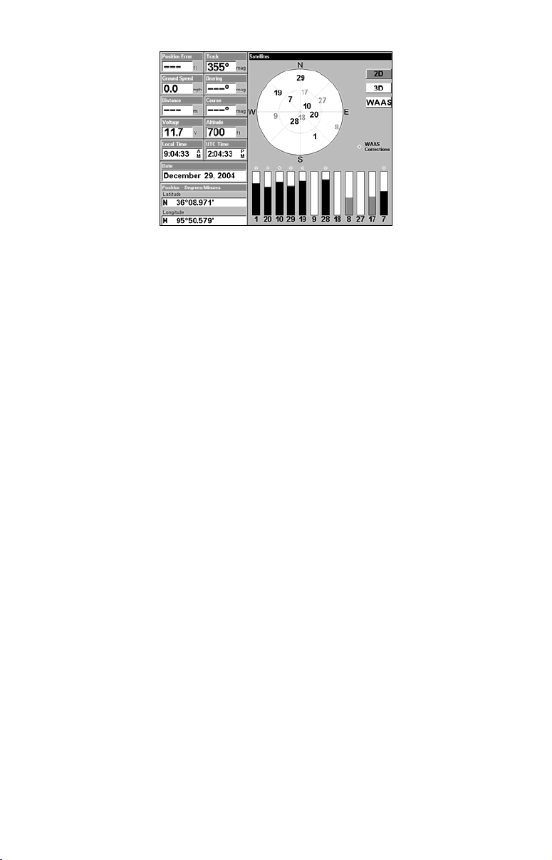
The Satellite Status Page.
This screen shows a graphical view of the satellites that are in view. Each
satellite is shown on the circular chart relative to your position. The point in
the center of the chart is directly overhead. The small inner ring represents
45° above the horizon and the large ring represents the horizon. North is at
the top of the screen. You can use this to see which satellites are obstructed
by obstacles in your immediate area if the unit is facing north.
The GPS receiver is tracking satellites that are in bold type. The receiver hasn't locked onto a satellite if the number is grayed out, therefore it isn't being used to solve the position.
Beneath the circular graph are the bar graphs, one for each satellite in
view. Since the unit has twelve channels, it can dedicate one channel
per visible satellite. The taller the bar on the graph, the better the unit
is receiving the signals from the satellite.
The "Estimated Position Error" (horizontal position error) shown in the
upper left corner of the screen is the expected error from a benchmark
location. In other words, if the EPE shows 50 feet, then the position
shown by the unit is estimated to be within 50 feet of the actual location. This also gives you an indicator of the fix quality the unit currently has. The smaller the position error number, the better (and more
accurate) the fix is. If the position error flashes dashes, then the unit
hasn't locked onto the satellites, and the number shown isn't valid.
The Satellite Status Page has its own menu, which is used for setting
various options (Options and setup are discussed in Sec. 5.). To access
the Satellite Status Page Menu, from the Status Page, press
MENU.
Navigation Page
This screen has a compass rose that not only shows your direction of
travel, but also the direction to a recalled waypoint. To get to the Navigation Page: Press
PAGES| → or ← to NAVIGATION|EXIT.
33
Page 42

The navigation screen looks like the one below when you're not navigating to a waypoint or following a route or trail. Your position is
shown by an arrow in the center of the screen. Your trail history, or
path you've just taken, is depicted by the line extending from the arrow. The arrow pointing down at the top of the compass rose indicates
the current track (direction of travel) you are taking.
Navigation
information
displays
Trail line
Track or compass heading indicator, showing direction of travel
Compass
rose
Present
position
arrow
The GlobalMap navigation Page, recording a trail, traveling east. Page
looks like this when the unit is not navigating to a waypoint, following
a route, or backtracking a trail.
When navigating to a waypoint, the Navigation screen looks like the
following figure. Your ground speed, track, distance and bearing to
waypoint, and course are all shown digitally on this screen.
NOTE:
Remember, when the Speed, Track and Position information displays are flashing, satellite lock has not been achieved and no position fix has been determined. A question mark will also flash on the
position arrow in the center of the compass rose.
Speed (ground speed) is the velocity you are making over the ground (If
you wish, you can customize the Speed window to display Closing
Speed instead. Closing Speed is also known as velocity made good. It's
the speed that you're making toward the waypoint. For instructions,
see the Customize Page Displays entry in Sec. 5.).
Track is the heading, or the current direction you are actually traveling. Bearing is the direction of a line-of-sight from your present position to the destination. No matter what direction you are steering, the
34
Page 43
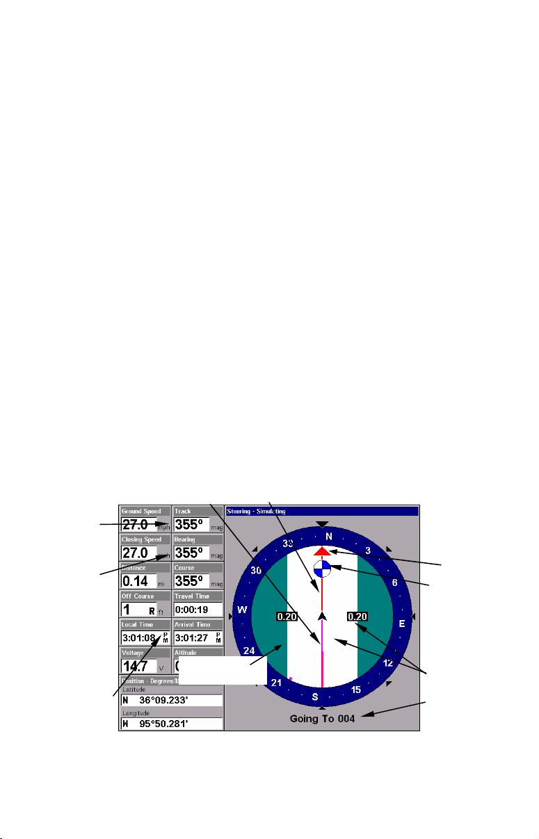
Bearing window shows the compass direction straight to the destina-
y
tion from your location at the moment. Distance shows how far it is to
the waypoint you're navigating toward.
The Off Course window shows the current cross track error. This shows
the distance you are off-course to the side of the desired course line. The
course line is an imaginary line drawn from your position when you
started navigating to the destination waypoint. The course line is shown
on the Navigation Page screen (and the Map Page screen) as a dotted line.
The cross track error range is shown on the compass rose as a wide,
white, corridor enclosing the course line. The outer edges of this white
corridor represent lines that show the current cross track error range.
The default for the cross track error range is 0.20 miles.
For example, if the present position symbol touches the right cross
track error line, then you are 0.20 miles to the right of the desired
course. You need to steer left to return to the desired course. You can
use the
ZIN or ZOUT keys to change the cross track error range.
A circular symbol depicting your destination (waypoint) appears on the
screen as you approach the waypoint, as shown on the screen in the
following figure.
Travel Time is the time that it will take to reach your destination at
your present closing speed (You can also customize the time window to
show Arrival Time instead. Arrival Time is the local time it will be
when you arrive at the destination, based upon your present closing
speed and track.).
Current track
or heading,
shown
in degrees
Compass
bearing to
destination
Navigation
information
displays
Trail line
Left cross
track error line
The GlobalMap navigation page, backtracking a trail while
Course line
creating a new trail.
Bearing
arrow
Waypoint
mbol
s
Cross track
error range
(off course
indicator)
Destination
name
35
Page 44
In the example above, the driver is headed north (a 355º track) toward a waypoint 355º (bearing) away. The cross track error range (white corridor) is 0.20
miles either side of the course. The driver is headed toward trail waypoint 4,
which is 0.14 miles away. The vehicle is virtually on course (off course 1 foot to
the right). Traveling at a speed of 27 mph, the driver will arrive at the waypoint in 19 seconds.
The Navigation Page has its own menu, which is used for some advanced functions and for setting various options (Options and setup are discussed in Sec. 5.).
To access the Navigation Page Menu, from the Navigation Page, press
MENU.
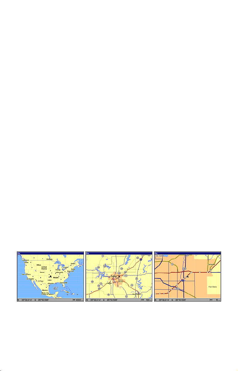
Map Page
The Map Page screens show your course and track from a "bird's-eye" view. By
default, this unit shows the map with north always at the top of the screen
(This can be changed. See the topic Map Orientation, in Sec. 5.). If you're navigating to a waypoint, the map also shows your starting location, present position, course line and destination. You don't have to navigate to a waypoint,
however, to use the map.
Map Page is the default screen that appears when you turn on the unit. To get
to the Map Page from another page: Press
PAGES| → or ← to MAP|EXIT. When
the Map Page is displayed, a screen similar to the following figures appears.
The arrow in the center of the screen is your present position. It points
in the direction you're traveling. The solid line extending from the back
of the arrow is your plot trail, or path you've taken.
The map zoom range is the distance across the screen. This number shows
in the lower right corner of the screen.
In the first example below, the range is 4,000 miles from the left edge of the
map to the right edge of the map.
The Zoom In and Zoom Out keys enlarge or reduce the map's coverage
area and the amount of mapping detail shown. There are 37 available
map zoom ranges, from 0.05 miles to 4,000 miles.
Map Page opening screen (left). Zoomed to 100 miles (center) and
zoomed to 15 miles (right). Over Zoomed means you have reached the
detail limits in an area covered only by the basic background map.
Zooming in any closer will reveal no more map details because a high-
detail custom map has not been loaded on the MMC.
36
Page 45

If you're using only the factory-loaded background map, the maximum
zoom range for showing additional map detail is 20 miles. You can continue to zoom in closer, but the map will simply be enlarged without
revealing more map content (except for a few major city streets). Load
your own high-detail custom map made with MapCreate, and you can
zoom in to 0.05 miles with massive amounts of accurate map detail.
Map Pages with high-detail MapCreate map of an urban area loaded on
the MMC. Arterial streets appear at the 6-mile zoom range with a few
Point of Interest icons visible (left). Numerous dots representing Points
of Interest become visible at the 3-mile range, along with minor streets
(center). At the 0.6-mile zoom, you can see an interstate highway with an
exit, major and minor streets as well as Point of Interest icons (right).
Background map vs. MapCreate map content
The background map includes: low-detail maps of the whole world, containing cities, major lakes, major rivers, political boundaries, and medium-detail maps of the United States.
The medium-detail U.S. maps contain: all incorporated cities, shaded
metropolitan areas, county boundaries, shaded public lands (such as
national forests and parks) and some major city streets. Also included
are Interstate, U.S. and state highways, large- and medium-sized lakes
and streams and more than 60,000 navigation aids with 10,000 wrecks
and obstructions in U.S. coastal and Great Lakes waters. New for 2007
are more than 3,000 enhanced lake maps that show better defined
shorelines, depth contours and other underwater features.
NOTE:
The GlobalMap HD models have NauticPath charts, Fishing Hot
Spots maps and all high detail MapCreate custom maps preloaded
on a 30 gigabyte hard drive. If you own an HD model you do not
need to load any of those high detail charts/maps into the unit. The
unit can also use Navionics charts, but they must be loaded via a
Navionics card.
MapCreate custom maps include massive amounts of information not
found in the background map. MapCreate contains: the searchable
Points of Interest database, all the minor roads and streets, all the
37
Page 46

landmark features (such as summits, schools, radio towers, etc.); more
rker
ring
rivers, streams, smaller lakes and ponds and their names.
What's more important is the large-scale map detail that allows your
GPS unit to show a higher level of position accuracy. For example, the background map would show you the general outline and approximate shape of a
coastline or water body, but the higher detail in MapCreate shows the shoreline completely and accurately (finer detail). Many smaller islands would not
be included in the background map, but are, of course, in MapCreate.
Minor
Streets
POI
Ma
School POI
Interstate
Major Street
Cursor line
POI Pop-up,
with position,
distance and
bea
data
Zoom Range
When the map is zoomed out far enough, most POIs appear as square
dots (left). As you zoom in closer, the symbols become readable icons.
In the 0.6-mile zoom example (right), the cursor has selected the Cupps
Café POI, which triggers a pop-up box with the POI name. This pop-up
box works on POIs at any zoom range.
Restaurant
POI
Tip:
In some urban areas, businesses are so close to one another that their
POI icons crowd each other on the screen. You can reduce screen clutter and make streets and other map features easier to see by simply
turning off the display of POIs you're not watching for (To see how,
check the text on Map Detail Category Selection, page 85. It shows
how to use the Map Categories Drawn menu to turn individual POI
displays off and on.).
The Map Page has its own menu, which is used for several functions
and for setting various options. To access the Map Page Menu, from the
Map Page, press
The Pages Menu also offers several map display options under the Map Page
category. To access them, press
MENU.
PAGES|← or→ to MAP|↓ to Option|EXIT.
38
Page 47

GlobalMap Digital Data page (left) and Two Position Formats page
(right).
Pages Menu with Two Maps option selected (left).
Map Page with two map windows (right). The right map is active.
In pages that have two major windows (such as two maps) you can toggle
back and forth between the two windows by pressing
PAGES|PAGES.
This allows you to change which map the cursor, keyboard and menus operate on. "Active window" will be displayed at the top of the active window.
Resize Window is another extremely handy feature for pages that have
two major windows. You can change the horizontal size of the windows
to suit your viewing preference. Here's how:
1. From any two-window display, press
MENU|↓ to RESIZE WINDOW|ENT.
2. Two flashing arrows appear along the centerline dividing the two windows. Press
← or → to adjust the window widths. Press EXIT to clear the
menu.
3. To change the window size again or go back to the original display,
just follow the steps above (Most dual-window displays use half the
screen for each window by default.). You can also use the Reset Options
command to revert to the factory default.
39
Page 48
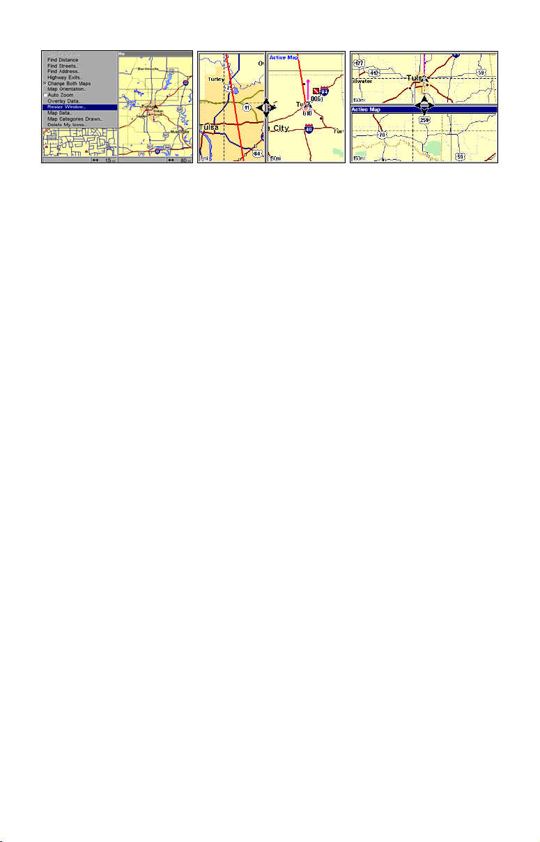
Map Menu with Resize Window command selected (left). Resize Win-
dow command is active (center). Pressing the ← → or ↑ ↓ keys allows
you to resize the windows from side to side or stack them one on top of
the other (right).
The following page contains a 12-step quick reference for the most basic
GPS operations. If you don't want to carry the manual with you as you
practice with the unit, you might consider photocopying this quick reference page and tucking it into your pocket.
40
Page 49

GPS Quick Reference
Start outdoors, with a clear view of the open sky. As you practice, try navigating to a location at least a few blocks away. While you're learning,
navigation in too small an area will constantly trigger arrival alarms.
1. Connect the unit to electric power and the antenna module. Make sure
the MMC is in. (See complete installation details beginning on page 9.)
2. To turn on the GlobalMap, press and release
3. Opening screen displays map of North America at the 4,000-mile
zoom range. Rotate through the three main Page screens (Map Page,
Satellite Status Page and Navigation Page) by pressing
to select Page Name|
EXIT. Switch Pages to display Satellite Status
Page.
4. Wait while unit locates satellites and calculates current position. Process
is visible on Satellite Page. This takes an average of 1 minute or less under
clear sky conditions (unobstructed by terrain or structures). When the unit
acquires position, a tone sounds and a position acquired message appears.
5. With position acquired, press
PAGES key to display Map Page, which
shows a bird's eye view of the earth. You can move around the map by:
Zoom in closer to see more detail: press
Zoom out to see more area, less detail: press
Scroll map north, south, east or west using arrow keys
To stop scrolling and return to current position on map, press
6. Set a waypoint (Wpt 001) at your current position so you can navigate back here: press
WPT|WPT. Waypoint symbol and "001" appears.
7. Zoom/scroll map to find a nearby object or location to go to. Use arrow keys to center cursor cross-hair over the map object or location.
8. Navigate to the selected destination: press
ted course line on Map Page or compass bearing arrow on Navigation Page.
9. At destination, Arrival Alarm goes off. To clear it, press
navigation: press
MENU|MENU|↓ to CANCEL NAVIGATION|ENT|← to YES|ENT.
10. Return to Wpt 1 by Navigate To Waypoint or Backtrack Trail. To
Waypoint: press
001, press
MENU|MENU|↓ to MY TRAILS|ENT. Press ↓ to Trail 1|ENT|→|↓ to NAVI-
GATE
|ENT|↓ to NAVIGATE |→ to REVERSE|ENT|← to NAVIGATE|ENT (If arrival
alarm sounds, press
WPT|→ to SAVED|ENT|ENT|ENT. Use ↑ or ↓ to select Wpt
ENT|ENT; follow navigation displays. Trail: press
EXIT.). Follow navigation displays.
11. Back home, Arrival Alarm goes off; press
press
MENU|MENU|↓ to CANCEL NAVIGATION|ENT|← to YES|ENT.
12. To turn off the unit, press and hold
PWR key for three seconds.
41
PWR key.
PAGES|← or →
ZIN (zoom in key).
ZOUT (zoom out key).
↑ ↓ → ← .
EXIT key.
MENU|ENT|EXIT. Follow dot-
EXIT. Cancel
EXIT. Cancel navigation:
Page 50

Find Your Current Position
Finding your current position is as simple as turning the GlobalMap
on. With an unobstructed view of the sky, the unit automatically
searches for satellites and calculates its position in approximately one
minute or less.
If for some reason satellite acquisition takes longer, you may be inside
a structure or vehicle or in terrain that is blocking signal reception. To
correct this, be sure you are positioned so that the unit's antenna module has as clear a view of the sky as possible, then turn the unit off and
back on again.
Moving Around the Map: Zoom & Cursor Arrow Keys
The map is presented from a bird's eye view perspective. The current
zoom range shows in the lower right corner of the screen.
1. Press the
smaller geographic area.
2. Press the
tail, but a larger geographic area.
When you are traveling, the map will automatically move as you move.
This keeps your current location roughly centered on the screen.
You can manually pan or scroll the map northward, southward, eastward or westward by using the arrow keys, which launch the cross-hair
map cursor. This allows you to look at map places other than your current position. To clear the cursor, press
back to the current position or the last known position.
ZIN key (zoom in) to move in closer and see more detail in a
ZOUT key (zoom out) to move farther away and see less de-
EXIT, which jumps the map
Tip:
Use the cursor to determine the distance from your current position
(or last known position when working indoors) to any map object.
Simply use the arrow keys to position the cursor over the object or
landmark. The distance, measured in a straight line, appears in the
pop-up box. Press
EXIT to clear the cursor.
42
Page 51

Cursor line
Selected
airport
POI pop-up
name box
Distance
measured
by cursor
Cursor line
The selected airport is 4.25 miles away, to the northwest.
Selecting Any Map Item with the Cursor
1. Use the zoom keys and the arrow keys to move around the map and
find the item you wish to select.
2. Use the arrow keys and center the cursor cross-hair on the desired
object. On most items, a pop-up box will give the name of the selected
item.
Searching
Now that you've seen how the GlobalMap can find where you are, let's
search for something else. Searching is one of the most powerful features in the Lowrance GPS product line.
In this example, we'll look for the nearest fast-food restaurant. For more
information on different types of searches, refer to Sec. 6, Searching.
NOTE:
This example requires the Point of Interest (POI) database included with a high detail MapCreate 6 custom map.
After the unit has acquired a position:
1. Press
WPT|↓ to POI-RESTAURANTS.
2. You could search the entire restaurant category, but in this example,
we will narrow our search. Press
FOOD CHAINS|ENT|↓ to NEAREST|ENT.
→ to SUBCATEGORY column|↓ to FAST
3. The unit says it is calculating, then a list of restaurants appears,
with the closest at the top of the list, and the farthest at the bottom of
the list. The nearest is highlighted.
43
Page 52
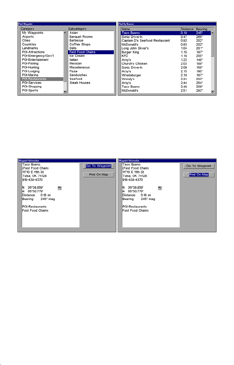
Category Selection menu (left); list of the nearest restaurants (right).
4. If you wish, you could scroll ↑ or ↓ here to select another restaurant,
but for now we will just accept the nearest one. Press
ENT.
5. The POI information screen appears (This is how you can use the
GlobalMap as a business phone directory!). If you wanted to navigate
there, you could press
But we just want to see it on the map, so press
ENT, since the GO TO command is highlighted.
↓ to FIND ON MAP|ENT.
The POI information screen shows name, street address, phone num-
ber, latitude/longitude, distance to restaurant and its compass bear-
ing. The Go To command (left); Find On Map command (right).
6. The unit's map appears, with the cross-hair cursor highlighting the
restaurant's POI symbol. A pop-up name box identifies the POI, as well
as its distance and bearing. A data box at the bottom of the screen continues to display the location's latitude and longitude.
7. To clear the search and return to the last page displayed, press
EXIT|EXIT|EXIT|EXIT (Before you completely exited out of the Search
menus, you could have gone looking for another place.).
44
Page 53

Map screen showing Find Waypoint, the result of a restaurant search.
NOTE:
Search works from mapping and POI data loaded in the GlobalMap. If you do not have a high-detailed custom map (containing
POI data) for the area you are searching loaded on the MMC, you
may not find anything.
Set a Waypoint
A waypoint is simply an electronic "address," based on the latitude and
longitude of a position on the earth. A waypoint represents a location,
spot, or destination that can be stored in memory, then be recalled and
used later on for navigation purposes.
You can create a waypoint at the cursor position on the map, or at your
current position while you are navigating. You can create a waypoint at
any location by manually entering the position's latitude and longitude.
You can copy waypoints from your unit to your personal computer with
MapCreate software. When you want to repeat a trip, these archived
waypoints can be reloaded into your GPS unit.
To create and save a Waypoint
These first two techniques use the Quick Save method, the fastest and
easiest way to create a waypoint.
Create Waypoint at Current Position
While you are traveling, press WPT|WPT. The waypoint is saved and
automatically given a name with a sequential number, such as "waypoint 003." The waypoint symbol and number appear on the map.
45
Page 54

Step 1.
Step 2.
Step 3.
Step 4.
Sequence for setting a waypoint. Step 1: while traveling, quickly press
WPT twice to call up Find Waypoint screen (seen in Step 2) and set a
point. Step 3: a message says the waypoint has been saved. Step 4: ve-
hicle continues on its way; number waypoint symbol is visible on map.
NOTE:
The Quick Save method uses the default waypoint symbol until you
edit an existing waypoint and change its symbol (Edit Waypoint
Symbol is described in Sec. 4.). After you have changed a waypoint
symbol, the unit will remember the one you chose and use it the
next time you "quick save" a waypoint. To return to the default
symbol, edit a waypoint and choose it, use the Reset Options command (described in Sec. 5).
Create Waypoint on Map
1. Use the arrow keys to move the cursor to the place where you want
to make a waypoint.
2. Press
WPT|WPT. The waypoint is saved and automatically given a
name with a sequential number, such as "waypoint 001." The waypoint
symbol and number appear on the map.
46
Page 55

Create Waypoint by Entering a Position
1. Press WPT|→ to SUBCATEGORY column|↓ to NEW|ENT.
2. Press
3. Press
↓ to ENTERED POSITION|ENT|→ to CREATE|ENT.
→ to LATITUDE|ENT. Enter the latitude by pressing ↑ or ↓ to
change the first character, then press → to the next character and repeat until the latitude is correct. Press
4. Press
↓ to LONGITUDE|ENT. Enter the longitude by pressing ↑ or ↓ to
ENT.
change the first character, then press → to the next character and repeat
until the longitude is correct. Press
ENT, then EXIT|EXIT to return to the
previous page display. The waypoint is saved and automatically given a
name with a sequential number, such as "waypoint 001." The waypoint
symbol and number appear on the map and in the waypoint list.
Navigate To a Waypoint
You can select any waypoint visible on the Map Page with the cursor,
then use the Navigate to Cursor command (we'll describe how later in
this section). You, however, can avoid scrolling the map to pick your
waypoint if you use the Find Waypoint commands:
1. Press
↓ to NEAREST|ENT; or, to look by name (and scroll through the entire
waypoint list), press
2. If your waypoint list is a long one, you can spell out the waypoint
name in the
first character, then press
and repeat until the name is correct, then press
below.).
WPT|→ to SAVED|ENT. To look up the nearest waypoint, press
ENT. For this example, look by name.
FIND BY NAME box to search for it (Press ↑ or ↓ to change the
→ to move the cursor to the next character
ENT to jump to the list
3. If the list is short, you can jump directly to the
pressing
ENT. Use ↑ or ↓ to select the waypoint name, press ENT and
the waypoint information screen appears with the
lected.
4. To begin navigating to the waypoint, press
ENT.
47
FIND IN LIST box by
GO TO command se-
Page 56
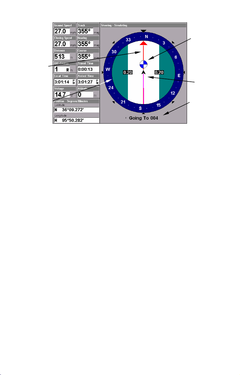
Waypoint
Course line
(dotted)
Trail line
(solid)
Off course
range, set at
0.20 mile
Destination
name
GlobalMap navigation Page, navigating toward waypoint 004 and leav-
ing a trail.
Set Man Overboard (MOB) Waypoint
One of boating's most terrifying events is having a friend or family
member fall overboard. This situation can be deadly on any body of water. It's particularly dangerous at night or if you're out of sight of land.
Of course, the first thing to do is remain calm and then use all standard
safety procedures to rescue the person.
This unit has a man overboard feature that shows navigation data to
the location where the feature was activated. To activate it, press the
ZOUT and ZIN keys at the same time. Your position at the time these
keys are pressed is used as the man overboard position.
Caution:
Saving a new "Man Overboard" waypoint will overwrite and
erase the previous "Man Overboard" waypoint.
Navigate Back to MOB Waypoint
Find your way back to the accident position with the Navigation Page
or Map Page. When MOB is activated, the Navigation Page automatically shows the compass rose with its bearing arrow pointing toward
the man overboard position, and the destination name says "Going To
Man Overboard." The Map Page displays a Man Overboard waypoint,
represented by a human figure, and the steering arrow points where to
steer to reach that position.
48
Page 57

Navigating to Man Overboard: navigation page (left) and Map Page
(right). The victim is astern of the vessel; the GPS shows which direc-
tion to steer to for the rescue.
The man overboard position is also stored in the waypoint list for future reference. It can be edited the same as any other waypoint.
To cancel navigation to MOB, press
|ENT|← to YES|ENT. The GlobalMap stops showing navigation infor-
TION
MENU|MENU|↓ to CANCEL NAVIGA-
mation.
Navigate to Cursor Position on Map
The GO TO CURSOR command navigates to the current cursor position on
the map. It's a quick and handy way to navigate to anything you can
see on the map display.
1. Use the cursor (controlled by the arrow keys) with the zoom in and
zoom out keys to maneuver around the map until you find a location
you want to go to.
2. Center the cursor over the location to select it. See the example in
the following figure (Many map items such as waypoints, Points of Interest, towns, etc. can be "selected," and appear "highlighted" with a
pop-up box. Other features, such as a river or a street intersection will
not appear "highlighted," but the cursor will take you to those locations
just the same.).
49
Page 58
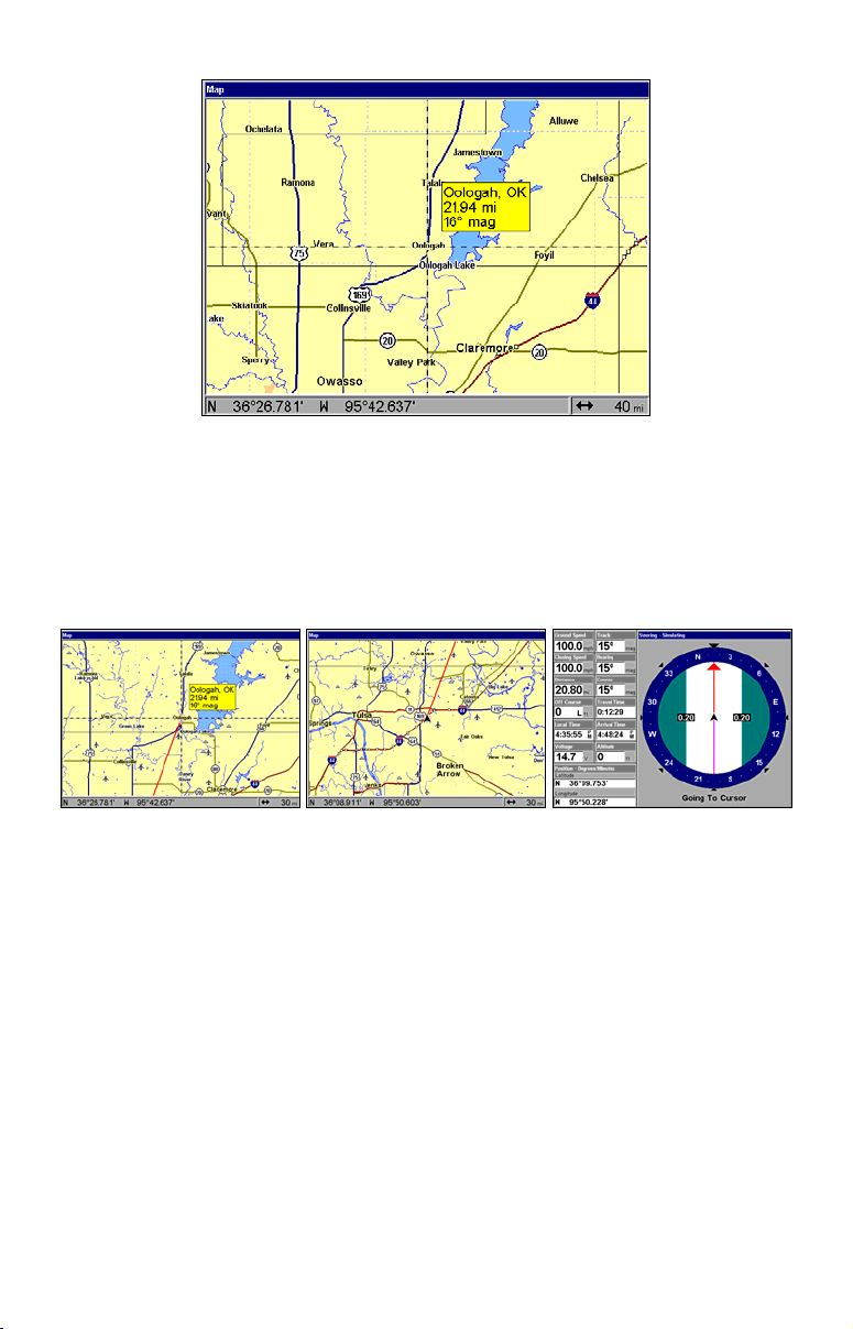
Navigate to cursor. In this example, the cursor is positioned on the
town of Oologah, Oklahoma.
3. Press MENU|ENT and the GlobalMap will begin navigating to the cursor location.
The Map Page will display a dotted line from your current position to the
cursor position. The Navigation Page displays a compass rose showing
navigation information to your destination. See the following examples.
The 30-mile zoom example (left) shows the dotted course line connect-
ing your current position to your destination. The other 30-mile zoom
example (center) shows both current position and direction to destina-
tion on screen. The Navigation Page (right) will also show navigation
information.
To stop navigating to the cursor, use the Cancel Navigation command:
press
MENU|MENU|↓ to CANCEL NAVI GATION|ENT|← to YES|ENT. The unit
stops showing navigation information.
Navigate to a Point of Interest
For POIs that are in view on the map, you can easily use the Navigate
to Cursor command above. Just use the cursor to select the POI.
The other method involves searching for POIs with the Find Waypoint
command, launched with the
lier in this section, or turn to Sec. 6, Searching, for detailed instructions
on POI searches.).
WPT key (See the searching example ear-
50
Page 59
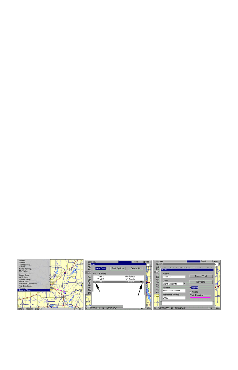
After you have looked up an item with the Find Waypoint command,
use the
the screen, then press
→ to make sure the GO TO command is highlighted at the top of
ENT. The GlobalMap begins showing navigation
information to the item.
To cancel navigation, press
to
YES|ENT. The unit stops showing navigation information.
MENU|MENU|↓ to CANCEL NAVIGATIO N|ENT|←
Creating and Saving a Trail
A trail, or plot trail, is a string of position points plotted by the GlobalMap as you travel. It's a travel history, a record of the path you have
taken. Trails are useful for repeating a journey along the same track.
They are particularly handy when you are trying to retrace your trip
and go back the way you came. On the screen, trails are represented by
a solid line extending from the back of the current position arrow.
The GlobalMap is set at the factory to automatically create and record
a trail while the unit is turned on. The unit will continue recording the
trail until the length reaches the maximum trail point setting (default
is 2,000, but the unit can record trails 9,999 points long). When the
point limit is reached, the unit begins recording the trail over itself.
By default, the trail flashes once a second, making it easier to see against
the background map. With the default auto setting, the GlobalMap creates a trail by placing a dot (trail point) on the screen every time you
change directions (The trail update rate and the methods used for creating
a trail can be adjusted or even turned off. See Sec. 5 for Trail Options.).
To preserve a trail from point A to point B, you must "turn off" the trail
by making it inactive before heading to point C or even back to point A.
When the current trail is inactive, the GlobalMap automatically begins
recording a new trail.
To Save a Trail
1. Press
2. Press
MENU|MENU|↓ to MY TRAILS|ENT.
↓ to choose a trail in the Saved Trails List|ENT.
Visible
symbol
Sequence for saving a trail and beginning a new one. My Trails com-
mand (left). The arrow to the right of Trail 17 (center) indicates the
trail is "active" and the check to the left shows the trail is visible on the
map. The Edit Trail menu (right) with Active command selected.
Active
symbol
51
Page 60

3. Press
4. To return to the previous page, press
↓ → to ACTIVE|ENT. This unchecks the Active option.
EXIT|EXIT|EXIT|EXIT. As you left the
Edit Trail menu, you will notice that a new trail was started with a new sequential number. In the example below, the new trail is number 15, showing
zero points. Note that Trail 14 is inactive, but it is still visible on the map.
A new trail, Trail 15, is created when Trail 14 is set to inactive. Any
new travel will be recorded on this trail, which is active and visible.
Trails do not need to be visible in order to be active.
You can save and recall up to 10 different plot trails, which can also be copied to your MMC for archiving or for transfer to your MapCreate software.
Tip:
Another quick way to stop recording one trail and begin a new one is to
use the New Trail command: Press
MENU|MENU|↓ to MY TRAILS|ENT|ENT.
Caution:
You also have the option of completely turning off trail recording,
under the trail Options command. If, however, the Update Active
Trail option is left turned off, it will cancel the automatic trail creation feature.
Displaying a Saved Trail
The active trail is automatically displayed on the map (the "Visible"
option) with the factory default settings. You can selectively turn trail
display off and on for any saved or active trail. In the Saved Trails List,
visible trails have a check mark in front of the trail name.
To turn off trail display:
1. Press
2. Press
sired Trail Name|
3. Press
press
MENU|MENU|↓ to MY TRAILS|ENT.
↓ to enter the Saved Trail list, then use ↑ or ↓ to select the de-
ENT.
↓ → to ACTIVE|↓ to VISIBLE|ENT. To return to the previous page,
EXIT|EXIT|EXIT|EXIT.
52
Page 61

To turn on trail display:
1. Press
2. Press
sired Trail Name|
3. Press
press
MENU|MENU|↓ to MY TRAILS|ENT.
↓ to enter the Saved Trail list, then use ↑ or ↓ to select the de-
ENT.
↓ → to ACTIVE|↓ to VISIBLE|ENT. To return to the previous page,
EXIT|EXIT|EXIT|EXIT.
Navigating Trails
There are three methods for following a trail: visual trailing, navigating a trail (forward) and backtracking a trail (backward). Try each
method to see which you prefer.
Visual trailing is the simplest method. It uses only the Map Page and
requires no menu commands at all. The technique works the same if
you are running a trail forward (from start to end) or backward (from
end to start). Visual trailing, however, provides no navigation information during the trip, such as the time to your destination.
The other two methods provide a full range of navigation data and
work with both the Map Page and Navigation Page. The only difference
between them is "navigating a trail" follows a trail forward, while
"backtracking" follows a trail in reverse.
When hiking at walking speed with a hand-held GPS, we often just use
visual back trailing because it is better following each little turn on a
foot path. At faster speeds — like traveling on the highway or on the
water — the Navigate Trail and Backtrack Trail commands are handy.
Visual Trailing
1. On the Map Page, zoom (
2. Begin moving and watch the Map Page. Simply walk or steer so your
current position arrow moves along the trail you have just made.
Tip:
Generally, when using this method, the smaller the zoom range,
the more accurately you will be able to steer along the trail.
Navigate a Trail (forward)
The following figures illustrate the menu sequence for navigating a trail.
1. Press
2. Press
Trail Name|
3. Press
MENU|MENU|↓ to MY TRAILS|ENT.
↓ to the Saved Trail list, then use ↑ or ↓ to select the desired
ENT.
→ to DELETE TRAIL|↓ to NAVIGATE|ENT.
ZIN or ZOUT) so your trail is visible.
4. Press
↓ to NAVIGATE|ENT. The unit begins showing navigation infor-
mation along the trail.
53
Page 62
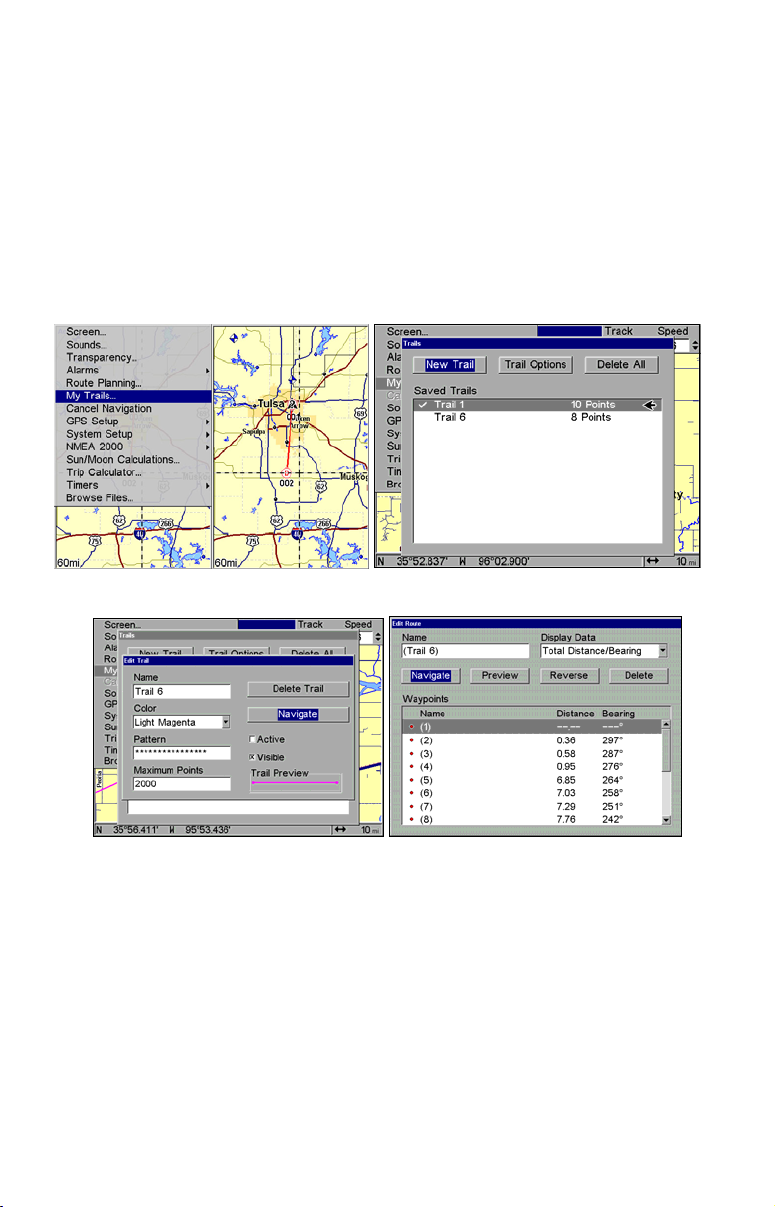
NOTE:
If you are already located at or near the beginning of your trail, the
arrival alarm will go off as soon as you hit Enter. Just press
EXIT to
clear the alarm.
5. Begin moving and let your GlobalMap guide you.
6. When you reach your destination, be sure to cancel your navigation:
press
MENU|MENU|↓ to CANCEL NAVIG ATION|ENT. The unit asks if you're
sure. Press
←|ENT.
Figure 1. Figure 2.
Figure 3.
Figure 4.
Navigate a trail menu sequence: Fig. 1, My Trails command. Fig. 2,
Trails Menu. Fig. 3, Edit Trail Menu. Fig. 4, Edit Route Menu with
Navigate command highlighted for Trail 6. A trail is always converted
to a "route" when you navigate the trail.
On the Map Page, the trail you are navigating is represented by a dotted
line that alternates with a flashing solid line. The Navigation Page will also
show the navigated trail as a dotted line. The bearing arrow on the compass
rose points to the next waypoint on the trail.
As you travel, the arrival alarm will go off when you near a waypoint. The
bearing arrow on the compass rose will swing around and point to the
next trail waypoint. Press
EXIT to clear the alarm.
54
Page 63
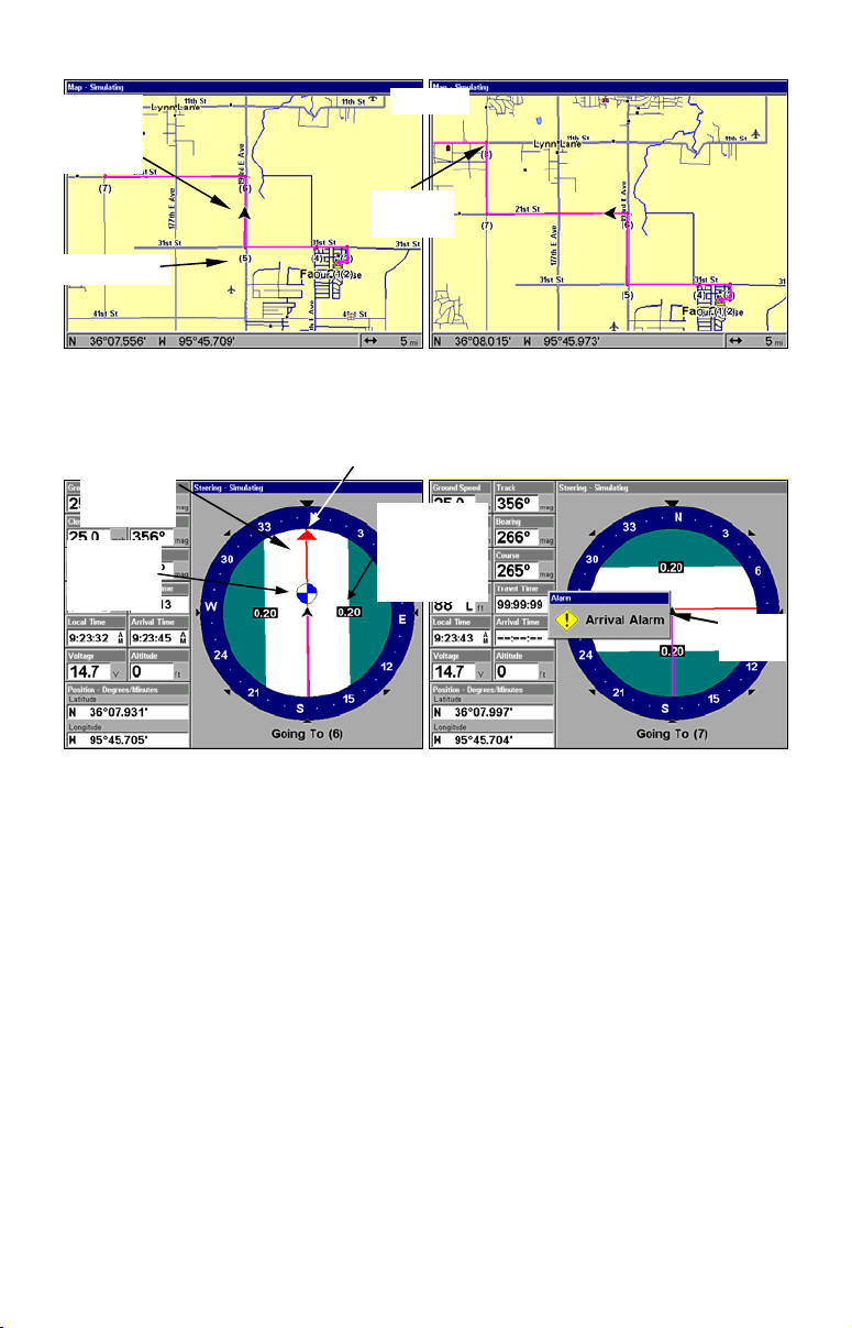
Present
position
arrow
Trail point
North Ï
Dotted
trail line
Navigate trail, map views: driver is northbound heading straight to-
ward trail point 6 (left). northbound driver has reached point 6 (right)
and has turned west to follow trail.
Course
line made
from trail
Trail
waypoint
symbol
Track or compass heading indicator
Cross track
error range
(off course
indicator)
Arrival
alarm
Navigate trail, navigation page (compass rose) views: driver is northbound heading straight toward trail point 6 (left); bearing arrow
shows the trail point is due north (straight ahead). Driver has reached
trail point 6 and must turn west to follow the trail (right). Arrival
alarm goes off and bearing arrow swings around to say turn left (west),
toward the next waypoint, trail point 7. The GlobalMap now shows
navigation information to point 7, which is 1.99 miles away.
Navigate a Back Trail (backtrack, or reverse)
1. Press
MENU|MENU|↓ to MY TRAILS|ENT.
2. Press ↓ to enter the Saved Trail list, then use ↑ or ↓ to select the desired Trail Name|
3. Press → to
ENT.
DELETE TRAIL|↓ to NAVIGATE|ENT.
4. Press
↓ to NAVIGATE|→ to REVERSE|ENT|← to NAVIGATE|ENT. The unit
begins showing navigation information along the trail, in reverse.
55
Page 64

NOTE:
If you are already located at or near the end of your trail, the arrival alarm will go off as soon as you hit
ENT. Press EXIT to clear the
alarm and proceed.
5. Begin moving and let your GlobalMap guide you.
6. When you reach your destination, be sure to cancel your navigation.
Press
MENU|MENU|↓ to CANCEL NAVIGATION|ENT. The unit asks if you're
sure. Press
←|ENT.
Transfer Custom Maps and GPS Data Files
Custom Maps
Custom maps work only from the MMC card or SD card unless you
have a hard drive model. When a card containing a Custom Map File is
loaded into the unit, it automatically loads the map into memory when
the unit is turned on.
Instructions for copying Custom Map Files to an MMC are contained in
the instruction manual for your MMC card reader and MapCreate software. For instructions on inserting an MMC into the GlobalMap, see
Sec. 2, Installation/Accessories.
NOTE:
To load a Navionics
®
chart, see Sec. 5 for the entry Navionics Charts.
GPS Data files
GPS Data Files contain waypoints, routes, trails and event marker
icons. Instructions for copying GPS Data Files between your computer
and an MMC are contained in the instruction manual for your MMC
card reader and MapCreate software.
GPS data automatically recorded in the unit's internal memory must
be saved to the MMC (as a GPS Data File) in order to store it on your
personal computer (If you have an HD model, these can also be saved to
the hard drive.). GPS Data Files stored on an MMC must be copied
from the card to the GlobalMap's internal memory before the unit can
read them. Here's how:
1. Insert the MMC into your unit. Press
SETUP|ENT|↓ to TRANSFER MY DATA|ENT and the dialog box below appears.
MENU|MENU|↓ to SYSTEM
56
Page 65

The Transfer My Data submenu asks if you want to save data to the
MMC or load data from the MMC into the unit's memory.
2. The Transfer My Data menu includes a message that tells you if a
MMC is present or not. If no MMC is present, you must insert a card to
activate the Load or Save commands.
To transfer data from the GlobalMap to the MMC press
To transfer data from the MMC to the GlobalMap press
ENT (for SAVE).
→ to LOAD|ENT.
3. Saving to MMC: To accept the default name "Data" for the GPS
Data File, press
shown in the following figures), press
lection box. Press
↓ to SAVE DATA|ENT. If you wish to rename the file (as
ENT to activate the file name se-
↑ or ↓ to change the first character, then press → to
the next character and repeat until the name is correct. Then, press
ENT|↓ to SAVE DATA|ENT.
The unit will display a completion message when the data transfer is
finished. To return to the Page view, repeatedly press
EXIT.
These figures (left to right) show the menu sequence for naming and
saving a GPS Data File from the GlobalMap's memory to an MMC.
57
Page 66
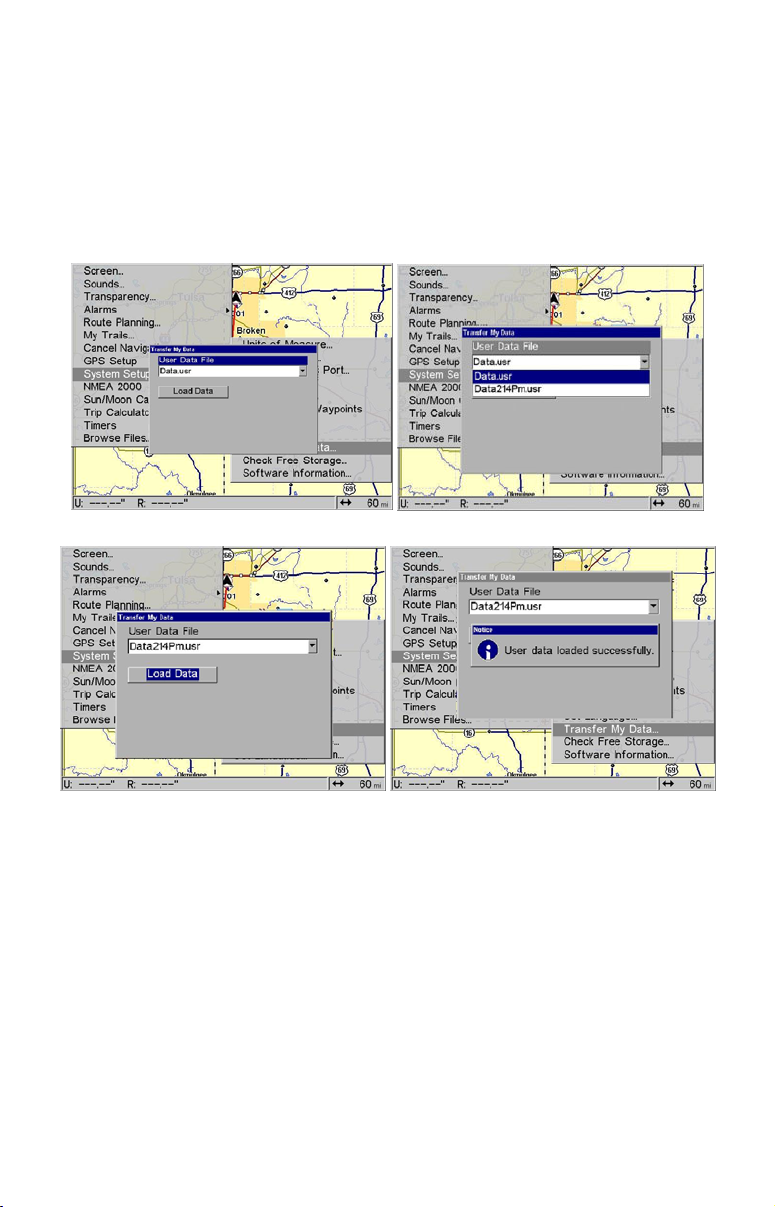
4. Loading to unit memory: There may be more than one GPS Data
File (*.USR) on the card. To select a file, press
tion box, use
selection. Next, press
↓ or ↑ to highlight the file, then press ENT to accept the
↓ to LOAD DATA|ENT. The unit will display a comple-
ENT to activate the selec-
tion message when the data transfer is finished. To return to the Page
view, press
EXIT repeatedly.
Figure 1.
Figure 2.
Figure 3.
Figure 4.
These figures show the menu sequence for loading a GPS Data File
from a MMC into the GlobalMap's memory.
Save GPS Data to Hard Drive
If you do not have a MMC or SD card, you can save any GPS data
(trails, routes, waypoints and icons) to the unit's hard drive. To do this
from the Map Page:
1. Press
2. Press
MENU| MENU| ↓ to SYSTEM SETUP
→ to TRANSFER MY DATA|ENT| ENT. A dialog box will appear on
screen. In this dialog box, you can choose whether to save the data to the
unit's hard drive or to a MMC card.
58
Page 67

3. Press
↓ to SAVE DATA| Press ENT
The data is now stored on the unit's hard drive.
NOTE:
If you do no have a MMC or SD card already in the unit, the data
information will automatically save to the unit's hard drive.
To retrieve the saved data information:
1.
MENU | MENU| ↓ to BROWSE FILE | ENT| ENT
2. Scroll through the list of files to find the one you want
3. Press
ENT|↓ to PLAY|ENT|EXIT
Cancel Navigation
You can turn off any of the navigation commands after you reach your
destination or at any other time by using the Cancel Navigation command. Press
MENU|MENU|↓ to CANCEL NAVIGATION|ENT|← to YES|ENT.
59
Page 68

Notes
60
Page 69
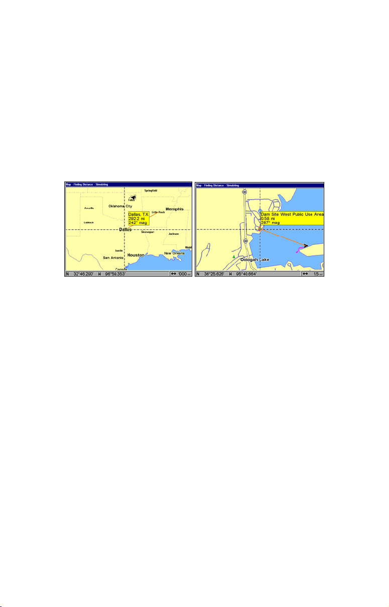
Section 4:
Advanced GPS Operations
Find Distance to Another Location
1. While on the Map Page press MENU|↓ to FIND DISTANCE|ENT.
2. To check the distance to a location, center the cursor over the desired position. A rubber band line appears, connecting your current position to the cursor's location. The distance along that line will appear in a pop-up box. The box
also shows the bearing to the location.
3. Press
The distance from Dallas to Little Rock is 292.2 miles (left). The distance
from the boat's current position to the boat ramp is 0.58 miles (right).
Find Distance From Point to Point
You can also measure distance between two other points on the map.
1. While on the Map Page press
2. Center your cursor over the first position (A rubber band line appears,
connecting your current position to the cursor's location.). Press
set the first point, and the rubber band line disappears.
3. Move the cursor to the second position. The rubber band line reappears,
connecting the first point you set to the cursor. The distance along that line
will appear in a pop-up box.
4. Press
Icons
Icons are graphic symbols used to mark some location, personal point of interest or event. They can be placed on the map screen, saved and recalled
later for navigation purposes. These are sometimes referred to as event
marker icons. The unit has 42 different symbols you can pick from when
creating an icon.
Icons are similar to waypoints, but they do not store as much information as
waypoints do. You can't use a menu to navigate to icons as you can with waypoints (But you can use the map cursor and navigate to any icon on the map.).
EXIT to return to regular operation.
MENU|↓ to FIND DISTANCE|ENT.
ENT to
EXIT to clear the command and return to the page screen.
61
Page 70
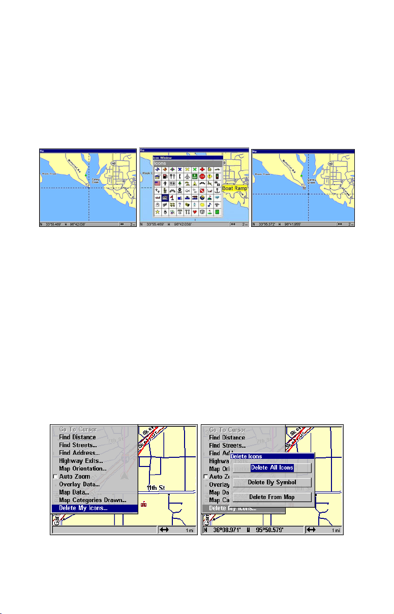
You can create an icon at the cursor position on the map, or at your
current position while you are navigating.
Create Icon on Map
1. Use the arrow keys to move the cursor to the location you want to
mark with an icon.
2. Press
3. Press
ENT and the screen shows a Select Icon Symbol menu.
← or ↑ or → or ↓ to select your icon symbol, then press ENT.
The icon appears on the map.
Cursor selects icon location (left); Select Icon Symbol menu (center);
Boat Ramp icon on map (right). The cursor has been moved for clarity.
Create Icon at Current Position
1. While you are traveling, press
ENT and the screen shows a "Select
Icon Symbol" menu.
2. Press
← or ↑ or → or ↓ to select your icon symbol, then press ENT.
The icon appears on the map.
Delete an Icon
You can delete all the icons at one time, you can delete all icons represented by a particular symbol, or you can use the cursor to delete a selected icon from the map.
1. Press
2. Press
press
MENU|↓ to DELETE MY ICONS|ENT.
↓ to DELETE ALL ICONS, DELETE BY SYMBOL, or DELETE FROM MAP and
ENT.
The Delete icons menus
62
Page 71

The Delete All Icons command will ask if you are sure. Press
YES|ENT. All icons will be deleted from the map.
← to
The Delete by Symbol command will launch the Select Symbol menu. Press
← or ↑ or → or ↓ to select the symbol to delete, then press ENT. A message
appears saying all icons with the selected symbol have been deleted.
The Delete from Map command will prompt you to move the cursor
over an icon to select it. After selecting the icon, press
ENT and it dis-
appears from the map.
Navigate to an Icon
Use the Navigate to Cursor command, and use the cursor to select the
desired icon on the map.
1. Use arrow keys to center cursor cross-hair over the icon.
2. To navigate to the selected icon location press
MENU|ENT|EXIT. Fol-
low the course line on the Map Page or the compass-bearing arrow on the
Navigation Page.
Routes
A route is a series of waypoints linked together in an ordered sequence
to mark a course of travel. You can visualize a route as a string of
beads. The beads represent waypoints and the string represents the
course of travel connecting waypoint to waypoint.
The course from one waypoint to the next is a leg. Routes are composed
of one or more legs. The legs of all GPS routes are based on straight
lines between waypoints.
A route gives users the capability to navigate through several waypoints
without having to reprogram the unit after arriving at each waypoint.
The GPS unit allows you to navigate forward or backward through a
route. You can even begin navigating in the middle of a route!
Create and Save a Route
You have the option of creating and editing a route in the unit, or you
can make a route on your computer with our MapCreate 6 software.
PC-created Routes
MapCreate is the easiest method for preparing a route, simply because
your PC's larger screen, keyboard and mouse are easier to manipulate.
To load a MapCreate route into the GlobalMap, follow instructions in MapCreate's manual for creating a route and saving it as part of a GPS Data
File (file format *.usr). Copy the GPS Data File to an MMC and insert the
MMC in the unit (See Sec. 2 for instructions on installing MMCs. To load
the GPS Data File into the GlobalMap's memory, see the entry on Transfer
Custom Maps & GPS Data Files in Sec. 3, Basic GPS Operations.).
63
Page 72
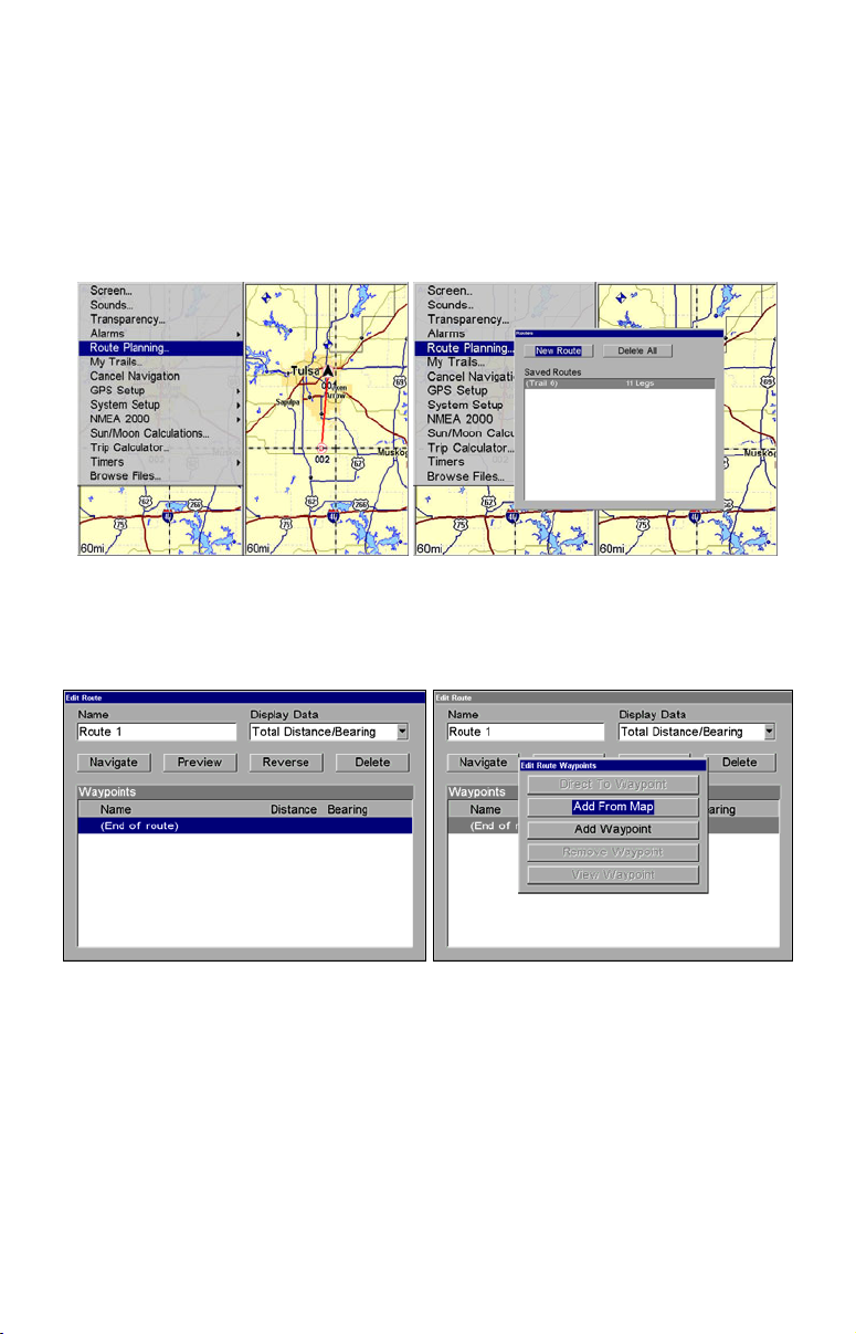
Routes Created in the GlobalMap
You can create a route by selecting existing waypoints from the waypoint list or you can set a series of route waypoints on the map with
cursor arrows and the Enter key. In this example, we'll create a route
from the map.
1. From the
press
MENU|MENU|↓ to ROUTE PLANNING|ENT.
NAVIGATION PAGE, press MENU|ENT or from the MAP PAGE,
Route Planning command on Main Menu (left),
will open the Route List screen (right). Copy one of the above trails
2. Press ↓ to route name|ENT|↓ to (END OF ROUTE)|ENT|↓ to ADD FROM
MAP|ENT. The Map Page appears with the cursor showing.
Edit Route menu (left). Edit Route Waypoints menu (right),
with Add From Map command selected.
3. Use the Zoom keys and arrow keys to move the map and cursor until
the cursor is centered on the spot where you want your route to begin
(If you are starting at your current position or the current cursor position, you are already at the starting spot.).
4. Set the first route waypoint and press
ENT. In this example, we
started our route at the intersection of 11th Street and 145th E. Ave.
The route is illustrated in the following figures.
64
Page 73

1.
2.
3.
Route creation sequence (left to right): Fig. 1. Set route waypoint (1) at
11th St. & 145th Ave. Fig. 2. Move cursor north to set point (2) at 145th
& Admiral. Fig. 3. With point (2) set, move cursor east to mark inter-
state on-ramp with waypoint (3). In figures 2 and 3, notice the rubber
band line extending from the previously set waypoint to the cursor.
This line will become the course for the route.
4. 5.
6.
Route creation sequence, continued: Fig. 4. Point (3) set at on-ramp
turn. Fig. 5. Waypoint (4) set at highway exit to frontage road leading
to river. Waypoint (5) ends the route at a tree stand in the hunting
area. Fig. 6. Press EXIT to save the route and you return to this screen.
5. Move the cursor to the next point in the route, a spot where you need
to turn or change direction, and press
ENT to set the next waypoint.
6. Repeat step five until the route reaches your destination.
7. To save your route, press
EXIT. The unit reverts to the Edit Route
screen, with the route automatically named "Route 1" and stored in the
GlobalMap's internal memory (In our example, Route 1 already existed,
so the unit automatically made "Route 2.").
You can edit the route and run other commands, but if you are finished
with the route for now, return to the last page displayed by pressing
EXIT repeatedly.
Delete a Route
1. From the
MENU|MENU|↓ to ROUTE PLANNING|ENT.
2. Press
3. Press
NAVIGATION PAGE, press MENU|ENT or from the MAP PAGE press
↓ to route name|ENT.
↓ to NAVIGATE| → to DELETE|ENT|← to YES|ENT.
65
Page 74
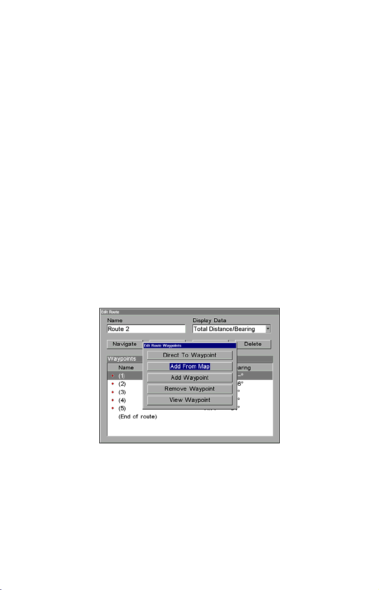
Tip:
You can also delete all routes at once:
1. From the
MENU|MENU|↓ to ROUTE PLANNING|ENT.
press
2. Press ↑ → to
NAVIGATION PAGE, press MENU|ENT or from the MAP PAGE
DELETE ALL|ENT|← to YES|ENT.
Edit a Route
You can edit the route name if you wish.
1. From the
MENU|MENU|↓ to ROUTE PLANNING|ENT.
2. Press
3. Press
NAVIGATION PAGE, press MENU|ENT or from the MAP PAGE press
↓ to route name|ENT|↑ to name | ENT.
↑ or ↓ to change the first character, then press → to move the
cursor to the next character and repeat until the name is correct, then
press
ENT. Return to the main page by pressing EXIT|EXIT|EXIT|EXIT.
You can edit the route by adding and removing waypoints.
1. From the
MENU|MENU|↓ to ROUTE PLANNING|ENT.
2. Press
waypoint, then press
NAVIGATION PAGE, press MENU|ENT or from the MAP PAGE press
↓ to route name|ENT|↓ to WAYPOINTS. Use ↓ and ↑ to select a
ENT.
Edit Route Waypoints menu.
3. Use ↓ and ↑ to select a command from the Edit Route Waypoints
menu and press
route by selecting a location with the cursor then pressing
ENT. Add From Map lets you insert a waypoint in the
ENT. Add
Waypoint calls up the Waypoint List so you can insert a waypoint from
the list. Remove Waypoint will delete the waypoint from the route.
View Waypoint will show you where the selected waypoint is on the
map.
66
Page 75
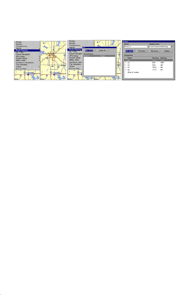
Navigate a Route
1. From the
press
MENU|MENU|↓ to ROUTE PLANNING|ENT.
NAVIGATION PAGE, press MENU|ENT or from the MAP PAGE,
Route Planning command on Main Menu (left); Routes menu (center);
Edit Route menu (right) with navigate command is selected.
2. Press ↓ to select route name|ENT|↓ to NAVIG ATE|ENT.
3. Upon arrival at your destination, cancel navigation:
press
MENU|MENU|↓ to CANCEL NAVIGATION|ENT|← to YES|ENT.
The following figures show what the Navigation Page and Map Page
look like while navigating a route.
Navigate a Route in Reverse
Here's how you run a route backwards, from the end waypoint to the
beginning waypoint.
1. From the
press
MENU|MENU|↓ to ROUTE PLANNING|ENT.
2. Press
to
NAVIGATE|ENT.
NAVIGATION PAGE, press MENU|ENT or from the MAP PAGE,
↓ to select route name|ENT|↑ to NAVIGATE|→ to REVERSE|ENT|←
3. Upon arrival at your destination, cancel navigation:
press
MENU|MENU|↓ to CANCEL NAVIGATION|ENT|← to YES|ENT.
67
Page 76

Figure 1.
Figure 2.
Figure 3.
Figure 4.
Navigating along a route: Fig. 1 shows the GlobalMap Navigation Page
at the start of a route, heading straight for the first waypoint (Wpt 1). In
Fig. 2, the traveler has arrived at Wpt 1; the arrival alarm has been triggered and the bearing arrow on the compass rose has turned to point
east, toward Wpt 2. In Fig. 3 the traveler has turned east on his new
course and is heading straight for Wpt 2, which is 2.15 miles away. Fig. 4
shows route navigation on the Map Page. In this figure, the traveler has
reached Wpt 2 and is half-way along the leg between Wpts 2 and 3.
Trails
Delete a Trail
This is the command used to erase or delete a trail:
MENU|MENU|↓ to MY TRAILS|ENT|↓ to trail name|ENT|→ to DE-
Press
LETE
TRAIL|ENT|← to YES|ENT.
Tip:
You can also delete all trails at once:
1. Press
2. Press
MENU|MENU|↓ to MY TRAILS|ENT.
→ to DELETE ALL|ENT|← to YES|ENT.
68
Page 77
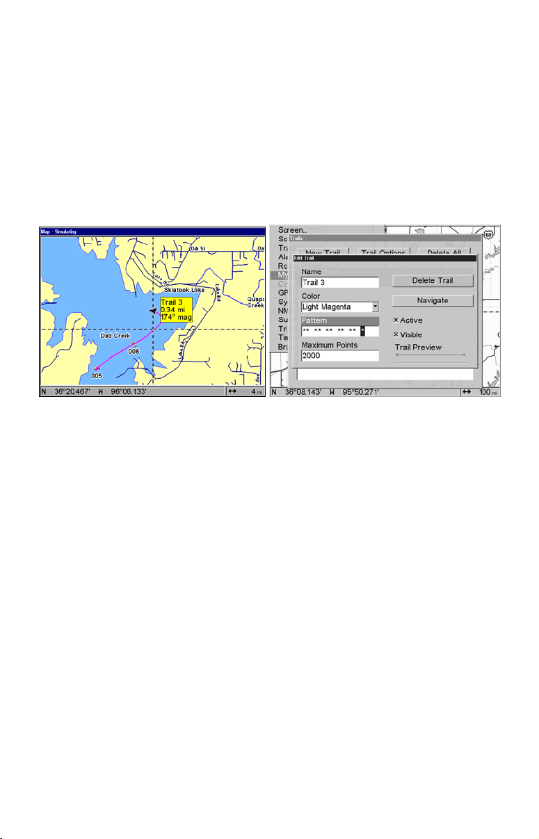
Edit a Trail Name
To edit a trail name: press
name|
ENT|ENT. Press ↑ or ↓ to change the first character, then press
MENU|MENU|↓ to MY TRAILS|ENT|↓ to trail
→ to the next character and repeat until the name is correct. Press
then
EXIT|EXIT|EXIT|EXIT to return to the previous page display.
Tip:
You can quickly call up the Edit Trail menu by selecting a trail on
the map with the cursor. Simply move the cursor over a trail and a
pop-up box appears. Press
Trail selected with map cursor (left). The pop-up box shows distance
and bearing from current position to the selected point on the trail.
The Edit Trail menu (right).
WPT and the Edit Trail menu opens.
ENT
Edit a Trail Color
To edit a trail color: press
name|
press
ENT|↓ to COLOR|ENT. Press ↑ or ↓ to select a color style, then
ENT. Press EXIT|EXIT|EXIT|EXIT to return to the previous page
MENU|MENU|↓ to MY TRAILS|ENT|↓ to trail
display.
Edit a Trail Pattern
To edit a trail pattern: press
name|
then press
rect. Press
ENT|↓ to PATTERN|ENT. Press ↑ or ↓ to change the first character,
→ to the next character and repeat until the pattern is cor-
ENT, then EXIT|EXIT|EXIT|EXIT to return to the previous
MENU|MENU|↓ to MY TRAILS|ENT|↓ to trail
page display.
69
Page 78
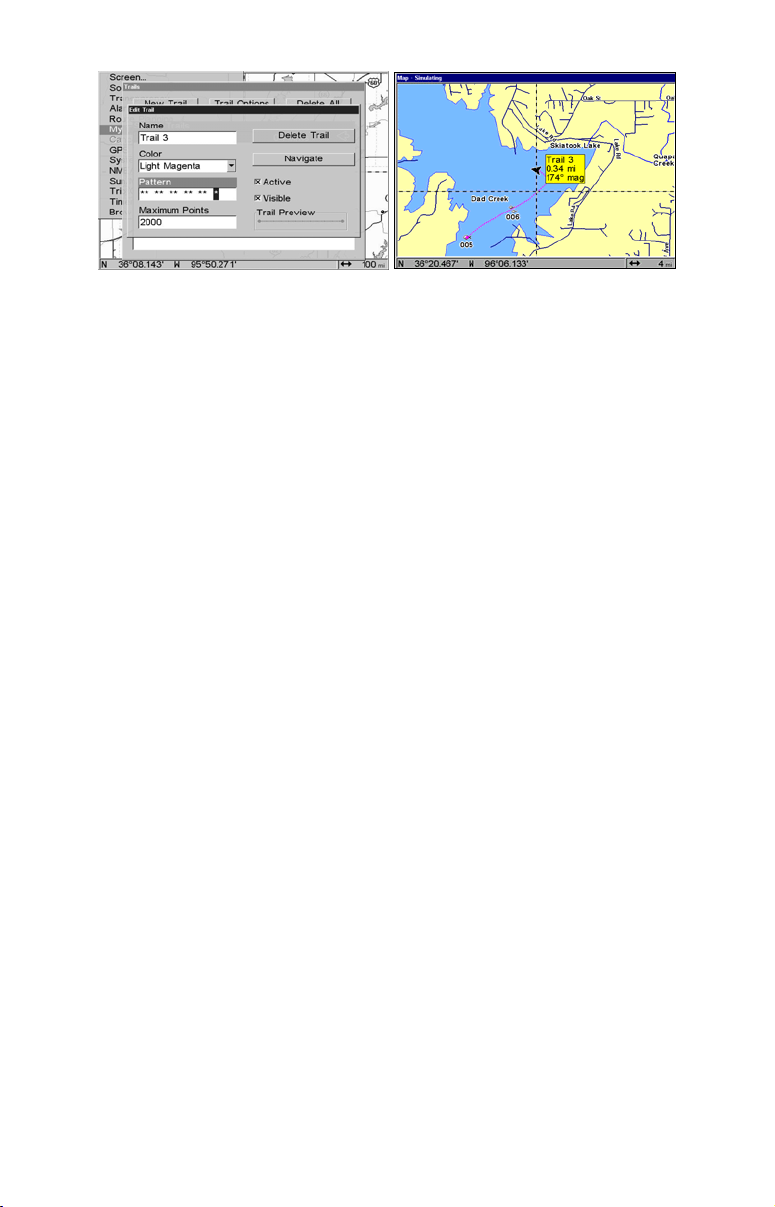
Edit Trail Menu with Pattern option selected (left). Edited trail with
dotted line pattern (right). transparency
Utilities
Utilities are useful tools for traveling or for outdoor activities.
Alarm Clock
To get to the alarm clock menu: press
to
ALARM CLOCK|ENT.
MENU|MENU|↓ to TIMERS|ENT|↓
Sun/Moon Rise & Set Calculator
To get to the Sun/Moon menu: press
LATIONS
|ENT.
MENU|MENU|↓ to SUN/MOON CALCU-
Trip Calculator
To get to the Calculator menu: press
TOR
|ENT.
MENU|MENU|↓ to TRIP CALCULA-
Trip Down Timer
To get to the Down Timer menu: press
to
DOWN TIMER|ENT.
MENU|MENU|↓ to TIMERS|ENT|↓
Trip Up Timer
To get to the Up Timer menu: press
MENU|MENU|↓ to TIMERS|ENT|ENT.
Waypoints
Delete a Waypoint
To delete a waypoint from the waypoint list: press
to waypoint name|
turn to the previous page, press
ENT|↓ to DELETE WAYPOINT|ENT|← to YES|ENT. To re-
EXIT|EXIT.
To delete a waypoint from the map:
1. Use the arrow keys to select the waypoint with the cursor.
2. Press
previous page and clear the cursor, press
WPT|↓ to DELETE WAYPOINT|ENT|← to YES|ENT. To return to the
EXIT.
WPT|ENT|ENT|ENT|↓
To delete all waypoints at one time: press
SETUP|ENT|↓ to DELETE ALL MY WAYPOINTS|ENT|← to YES|ENT. To return
to the previous page, press
EXIT|EXIT.
MENU|MENU|↓ to SYSTEM
70
Page 79

Edit a Waypoint
Waypoint Name
To edit waypoint name: 1. Press WPT|ENT|ENT|ENT|↓ to waypoint
name|
2. Press ↑ or ↓ to change the first character, then press
character and repeat until the name is correct. Press
EXIT|EXIT|EXIT|EXIT to return to the previous page display.
Waypoint Symbol
ENT|↓ to EDIT WAYPOINT|ENT|ENT.
→ to the next
ENT then
To edit waypoint symbol: 1. Press WPT|ENT|ENT|ENT|↓ to waypoint
name|
2. Use arrow keys to select desired symbol and press
the previous page, press
Waypoint Position
ENT|↓ to EDIT WAYPOINT|ENT|↓ to CHOOSE SYMBOL|ENT.
ENT. To return to
EXIT|EXIT|EXIT|EXIT.
To edit waypoint position: 1. Press WPT|ENT|ENT|ENT|↓ to waypoint
name|
2. Latitude: press
ENT|↓ to EDIT WAYPOINT|ENT.
→ to LATITUDE|ENT. Press ↑ or ↓ to change the first
character, then press → to the next character and repeat until the latitude is correct. Press
3. Longitude: press
EXIT.
↓ to LONGITUDE|ENT. Press ↑ or ↓ to change the first
character, then press → to the next character and repeat until the longitude is correct. Press
EXIT.
4. When latitude and longitude are correct, return to the previous page:
press
EXIT|EXIT|EXIT|EXIT.
Selecting a Waypoint
To select a waypoint on the map (for navigating, editing, etc.,) use the
arrow keys and center the cursor over the waypoint. A highlighted halo
will appear around the waypoint.
Set a Waypoint by Average Position
This feature sets a waypoint at the current position after taking several position readings and averaging them. This boosts waypoint position accuracy by
helping to eliminate errors caused by atmospheric conditions and other factors.
1. Press
2. Press
WPT|→ to SUBCATEGORY column|↓ to NEW|ENT.
↓ or ↑ to AVERAGE POSITION|ENT|press → to CREATE|ENT.
3. Wait while the unit takes points to average for the position (The
greater the number of points, the greater the accuracy.). When the desired number of points accumulates, press
ENT to create and save the
waypoint.
4. The Edit Waypoint menu appears. You can simply save the waypoint
by pressing
EXIT|EXIT or you can edit the waypoint.
71
Page 80

Set a Waypoint by Projecting a Position
This feature sets a waypoint at a point located a specific distance and
bearing from a reference position. The reference position may be a map
feature or can be selected from your waypoint or Points of Interest lists.
1. Press
2. Press
3. Press
WPT|→ to SUBCATEGORY column|↓ to NEW|ENT.
↓ to PROJECTED POSITION|ENT|→ to CREATE|ENT.
→ to CHOOSE REFERENCE|ENT. Use ↑ and ↓ to select a waypoint,
map feature or Point of Interest. When the feature has been selected,
press
ENT. Now choose the reference point by its name or select the one
nearest your location and press
the list then press
ENT|ENT, which will take you back to the project
ENT. Choose your reference point from
waypoint screen.
4. Press
then press
rect. Press
5. Press
then press
rect. Press
6. Press
simply save the new projected waypoint by pressing
can edit the waypoint (Press
↓ to DISTANCE|ENT. Press ↑ or ↓ to change the first character,
→ to the next character and repeat until the distance is cor-
ENT.
↓ to BEARING|ENT. Press ↑ or ↓ to change the first character,
→ to the next character and repeat until the bearing is cor-
ENT.
↑ to PROJECT|ENT. The Edit Waypoint menu appears. You can
EXIT|EXIT or you
EXIT|ENT if you want to begin navigating
to the new waypoint.).
Set a Waypoint by Entering a Position
This feature allows you to enter a position if you know the altitude,
depth, latitude or longitude for the waypoint. To do this:
1. Press
WPT|→ to SUBCATEGORY column|↓ to NEW|ENT.
2. Press
↓ to ENTERED POSITION|ENT|→ to CREATE|ENT.
A dialog box will appear on screen. Within the dialog box you can name
the waypoint, enter waypoint's altitude, depth, latitude and longitude.
To enter the waypoint's latitude and longitude in the dialog box.
1.
→ to LATITUDE|ENT. Press ↑ or ↓ to change the first character, then
press
→ to the next character and repeat until the latitude is correct.
Press
ENT.
2.
↓ to LONGITUDE. Repeat the above steps to enter the waypoint's longi-
tude (Press
EXIT|ENT if you want to begin navigating to the new way-
point.).
72
Page 81
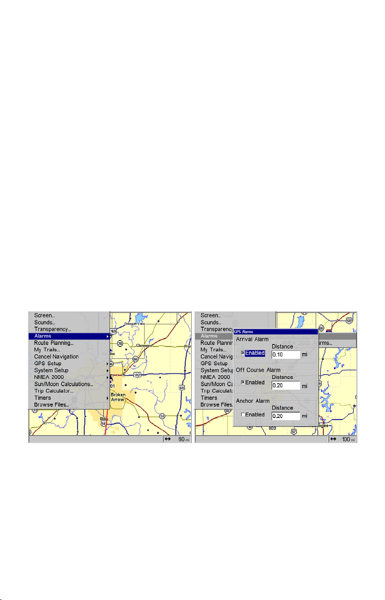
Section 5:
System & GPS Setup Options
Alarms
This unit has three GPS alarms. The factory default setting has all the
alarms turned on. You can turn the alarms off and on and change their
distance settings.
You can set an arrival alarm to flash a warning message and sound a
tone when you cross a preset distance from a waypoint. For example, if
you have the arrival alarm set to 0.1 mile, then the alarm will flash a
message when you come within 0.1 mile of the recalled waypoint.
The off course alarm warns you when your track drifts too far to the
right or left of the course line to the waypoint. For example, if the
alarm is set to 0.1 mile, then the alarm flashes a message if you drift
0.1 of a mile or more to the right or left of the line to the waypoint.
The anchor alarm is triggered when you drift outside a preset radius.
Again, using the 0.1 mile as an example, if you're anchored and your
boat moves more than 0.1 mile, the alarm will flash a message and
sound a tone.
Alarms command (left); Alarm menu (right).
To change alarm settings:
1. Press
2. Scroll
clear the Enabled box. This turns the alarm on (checked) or off (unchecked).
MENU|MENU|↓ to ALARMS|ENT|ENT.
↓ or ↑ to select the desired category, then press ENT to check or
73
Page 82

3. To change distance settings, scroll
gory, then press
→|ENT to activate the distance dialog box. Press ↑ or ↓
↓ or ↑ to select the desired cate-
to change the first character, then press → to the next character and
repeat until the name is correct.
4. When your adjustments are finished, return to the last page displayed by repeatedly pressing
EXIT.
IMPORTANT ALARM NOTES:
Anchor Alarm — The anchor alarm may be triggered even when
you're sitting still. This typically happens when using small (less
than 0.05 mile) anchor alarm ranges.
Arrival Alarm — If you set the arrival alarm's distance to a small
number and run a route (see the Navigate Routes segment), this
unit may not show navigation data to the next waypoint once you
arrive at the first waypoint. You may not be able to come close
enough to the first waypoint to trip the arrival alarm.
Auto Satellite Search
To lock onto the satellites, the GPS receiver needs to know its current
position, UTC time and date. It needs this data so it can calculate
which satellites should be in view. It then searches for only those satellites. Elevation (altitude) is also used in the equation, but it's rarely
required to determine a position.
When your GPS receiver is turned on for the first time, it doesn't know
your position or elevation (altitude). It does know the current UTC time
and date since these were programmed into it at the factory and an internal clock keeps the time while the unit is turned off (If the time
and/or date are incorrect, you can set it using the "Set Local Time" feature in the System Setup menu.).
The unit begins searching for satellites using the data it acquired the
last time it was turned on, which was probably at the factory. Since it's
almost certain that you're not at our factory, it's likely that it could be
looking for the wrong satellites.
If it doesn't find the satellites it's looking for after approximately one
minute, it switches to Auto Search. That's when the receiver looks for
any satellite in the sky. Due to advanced technology, the auto search
time has shrunk significantly from the early days of GPS.
Once the unit locks onto the satellites, it should take less than a minute to
find your position the next time it's turned on, provided you haven't
moved more than 100 miles from the last location it was used.
74
Page 83
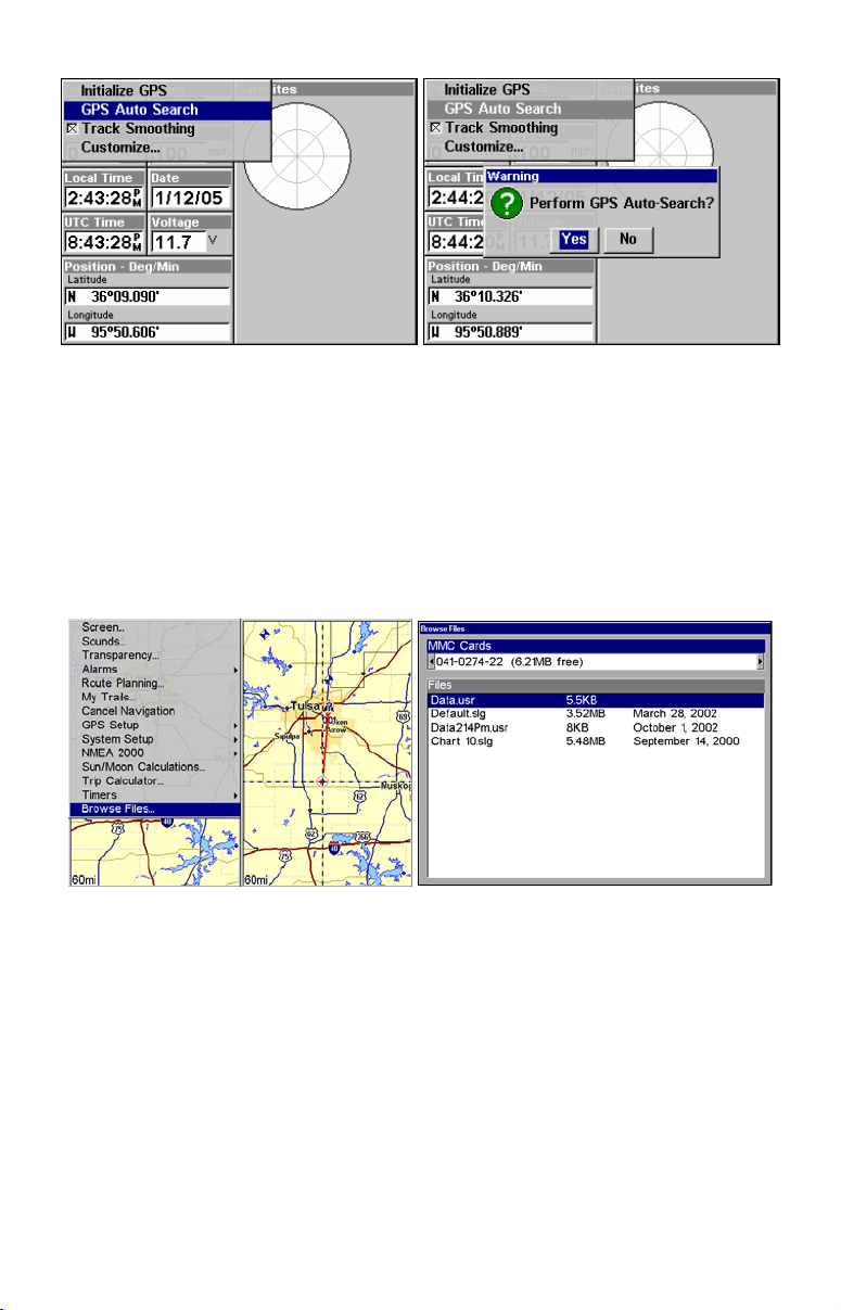
GPS Auto Search on the GlobalMap Satellite Status Menu.
Here's how to put the unit into auto search mode:
1. Press
2. Press
PAGES until you are on the Satellite Status screen.
MENU|↓ to GPS AUTO SEARCH|ENT|← to YES|ENT.
Check MMC Files and Storage Space
To check MMC Files:
Press
MENU|MENU|↓ to BROWSE FILES|ENT.
Main Menu (left), MMC File Browser (right).
Communications Port Configuration
The unit has two NMEA 0183 version 2.0 compatible communication
ports, or com ports for short. The Com Port Menu, which is accessed
from the System Setup Menu, allows you to configure the communications ports to send or receive data to another electronic device, such as
an autopilot. Com port 1 and Com port 2 can be used for NMEA.
75
Page 84

System Setup Menu with Communications Port highlighted (left) and
Communications Port menu (right).
For assistance in configuring the unit to communicate with another
device, consult the factory. Customer service phone numbers are in the
back of this manual. Also see the entry below for to Configure NMEA.
To set Com Port Configuration:
1. Press
2. Press
MENU|MENU|↓ to SYSTEM SETUP|ENT.
↓ to COMMUNICATIONS PORT|ENT.
Configure NMEA
You can configure the unit to use specific NMEA sentences.
1. Press
2. Press
MENU|MENU|↓ to SYSTEM SETUP|ENT.
↓ to COMMUNICATIONS PORT|ENT|→ to CONFIGURE NMEA|ENT.
3. A menu appears showing the prefixes of the available NMEA sentences. A check mark next to a prefix means the prefix is in use. Use
↓ → ← to select a prefix. Press ENT to turn on or off the prefix.
↑
4. When the desired prefixes are checked or unchecked, press
EXIT|EXIT|EXIT|EXIT to return to the previous page.
Coordinate System Selection
The Coordinate System Menu lets you select the coordinate system to
use when displaying and entering position coordinates.
76
Page 85

Menus for changing coordinate system.
To get to Coordinate System Selection:
1. Press
MENU|MENU|↓ to GPS SETUP|ENT.
2. Press
↓ to COORDINATE SYSTEM|ENT.
This unit can show a position in degrees (36.14952°); degrees, minutes
and thousandths of a minute (36° 28.700'); or degrees, minutes, seconds
and tenths of a second (36° 28' 40.9"). It can also show position in: UTM
(Universal Transverse Mercator) projection; MGRS (Standard); MGRS
(Standard + 10); Map Fix; Loran TD; British, Irish, Finnish, German,
New Zealand, Swedish, Swiss, Taiwan, Greek and Military grids.
UTM's are marked on USGS topographic charts. This system divides
the Earth into 60 zones, each 6 degrees wide in longitude.
British, Irish, Finnish, German, New Zealand, Swedish, Swiss, Taiwan,
and Greek grid systems are each the national coordinate system used
only in their respective countries. In order to use these grid systems,
you must be in the respective country. This unit will pick the matching
datum for you when you select the grid. See the entry on Map Datum
Selection for more information.
The military grid reference system (MGRS) uses two grid lettering
schemes, which are referred to as standard and standard + 10 MGRS
on this unit. Your position and datum in use determines which one to
use. If you use standard, and your position is off significantly, then try
the alternate.
NOTE: When the position format is changed, it affects the way all positions are shown on all screens. This includes waypoints.
To change the coordinate system, press
highlighted. Press
Press
ENT to select it. Press EXIT to clear the menus.
↑ or ↓ arrow keys to highlight the desired format.
77
ENT while COORDINATE SYSTEM is
Page 86

To setup Loran TD:
NOTE:
If the Loran TD conversion is chosen, you must enter the local Loran chain identification for the master and slaves. Do this by selecting "Setup Loran TD" at the bottom of the "Coordinate System"
menu, press
ENT, and select the ID. Press EXIT to clear this menu.
Configure Loran TD menu.
Map Fix
Map Fix is used with charts or maps. This system asks for a reference
position in latitude/longitude, which you take from a marked location
on the map. It then shows the present position as distance on the map
from that reference point.
For example, if it shows a distance of UP 4.00" and LEFT 0.50", you
then measure up four inches and to the left a half-inch from the reference point to find your location on the map.
Configure a map fix:
First, take your map of the area and determine a reference latitude/longitude (Please note that in order for this system to work, the
latitude/longitude lines must be parallel with the edge of the map.
USGS maps are parallel, others may not be. Also, this works better
with smaller scale maps.). The reference position can be anywhere on
the map, but the closer it is to your location, the smaller the numbers
will be that you'll have to deal with.
Once you've decided on a reference position, you can save it as a waypoint. See the waypoint section for information on saving a waypoint.
Save the reference position as a waypoint. Exit from the waypoint
screens.
78
Page 87

1. Press
MENU|MENU|↓ to GPS SETUP|ENT.
2. Press
3. Press
The following screen appears, and
↓ to COORDINATE SYSTEM|ENT.
↓ to SETUP MAP FIX|ENT.
MAP SCALE is highlighted. Press ENT
and enter the map's scale. This is generally at the bottom of a paper
map. It's shown as a ratio, for example 1:24000. Press
EXIT and the unit
returns to the Configure Map Fix screen.
Configure a map fix so the GlobalMap can find your position on a
printed chart or topographical map.
Press ↓ to SELECT ORIGIN WAYPOINT|ENT|ENT|ENT to bring up the waypoint list. Select the waypoint that you saved the reference point under
and press
the command
the Configure Map Fix menu. Finally, press
Now press
ENT|EXIT|EXIT|EXIT. All position information now shows as a distance
ENT. The unit displays a waypoint information screen with
SET AS ORIGIN selected. Press ENT and the unit returns to
EXIT to clear this menu.
↑ to COORD SYSTEM|ENT, select MAP FIX from the list and press
from the reference point you chose.
Customize Page Displays
Every Page display option except Full Map, Two Maps and Map With
Customize Gauges (on the Map Page) has customizable data boxes to
provide constant on-screen information.
The various data available from your unit are divided into categories in
the Data Viewer menu. These categories include GPS Data, Navigation,
Trip Calculator, Time, and Miscellaneous Data. You can select items
from any of these categories for display in any data box — the category
divisions are only there to help you sort through the information.
79
Page 88

To change the information displayed in a data box:
On the Page display you wish to change, press
ENT
. You'll see a list of categories with "+" or "–" symbols next to each cate-
gory. A category with a "+" is expandable, meaning its contents are hidden.
MENU|↓ to CUSTOMIZE|ENT|
Customize Menu, with the GPS Data category expanded.
Selecting the category name and pressing ENT will show the category's
contents, so you can choose items within it. An expanded category (one
with a "–" next to its name) can be collapsed to hide its contents. Just
select the category name and press
ENT.
Expand any categories that might contain data you want to display.
Then press ↓ or ↑ to select a different data option. With the new option
highlighted, press
type, then press
you are finished with the settings, press
ENT to switch the contents of the box to the new data
EXIT. You can now select another box to change. When
EXIT again to end the Custom-
ize command, and the box name stops flashing.
A Page display can show a limited number of data boxes. You cannot
turn them off or add more data boxes.
GPS Simulator
The GPS simulator lets you use the unit as if you were outdoors navigating somewhere. It's a great way to become familiar with all the unit's features. You can set the starting location by entering latitude/longitude
(Starting Position) or from a stored waypoint, map place or POI location
(
CHOOSE START command). You can steer your position and change speed
on the map by using the arrow keys (
setting the track and speed in the dialog boxes provided on the simulator
menu screen.
STEER WITH ARROWS command) or by
80
Page 89
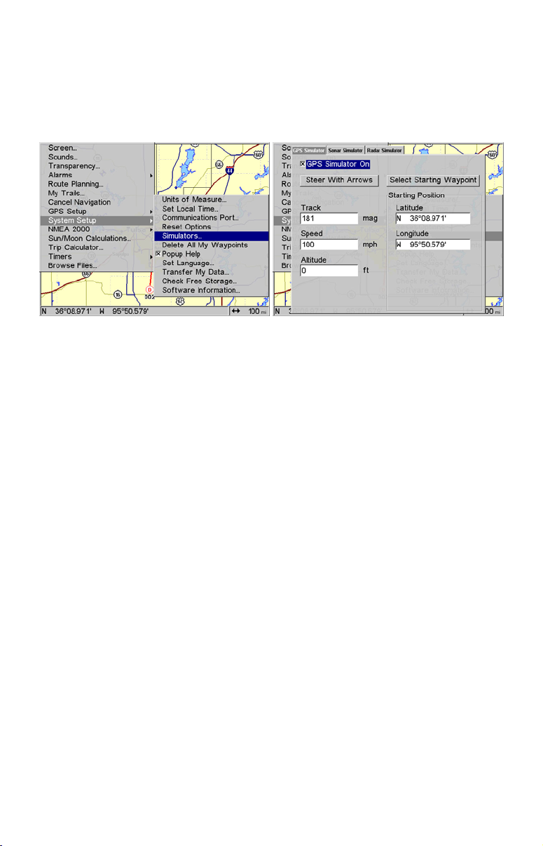
To get to the GPS Simulator:
1. Press
MENU|MENU|↓ to SYSTEM SETUP|ENT.
2. Press
3. Press
↓ to SIMULATORS|ENT. The GPS Simulator Menu appears.
↓ to GPS SIMULATOR ON | ENT
GPS Setup Menu (left); GPS Simulator menu (right).
Make the desired settings, then turn the simulator on by highlighting
the
GPS SIMULATOR ON box and pressing ENT key. Press EXIT|EXIT|EXIT
to clear this menu. A message and tone appear periodically, warning
you that the simulator is on. To turn the simulator off, repeat the above
steps or turn off the unit.
While in simulator mode, you can press
EXIT to clear the steering and
speed boxes from the screen while continuing the simulation. This will
allow you to use the map cursor during a simulation. To turn steering
and speed boxes back on again, return to the GPS Simulator menu, select
the
STEER WITH ARROWS command, press ENT, then press EXIT|EXIT|EXIT to
return to the previous page.
Simulating Trail or Route Navigation
In Simulator mode, your unit can automatically follow a trail or route
without manual steering if you use these steps:
1. Go to the simulator menu as shown above. Pick a
near the beginning of your trail/route. Enter an approximate
STARTING POSITION at or
TRACK (shown
in compass degrees) that will point you toward the start of the trail/route.
2. Set
SPEED to zero. Select STEER WITH ARROWS command and press ENT,
which turns on the simulator and returns you to the Map Page.
3. Begin navigating along the trail/route (If you are close enough to the
first waypoint, the arrival alarm will usually go off as soon as navigation begins. Press
press
↑ to increase speed to the desired setting.
EXIT to clear the alarm.). When navigation starts,
81
Page 90

4. Press
automatically "steer" along the trail or route. When you arrive at your
"destination," cancel navigation as you normally do.
EXIT to turn off the steering and speed boxes. The unit will now
Tip:
You can pick any spot on the map to begin your simulation session
by using the Initialize GPS command. This makes your unit think
it's located at the position you select. See the following entry.
Initialize GPS
This command is handy when you are practicing in simulator mode
(See the entry in this section for GPS Simulator.). In simulator mode,
this command makes the unit operate as if it is sitting someplace other
than its actual location. So, you and your unit could be located in Kansas City, but practice navigating in the ocean off Islamorada, Florida.
1. Press
2. A message appears, telling you to move the cursor near the desired
location and press
the message instructions.
3. In a moment, your present position marker arrow appears on the
map in the location you selected with the cursor. The unit will consider
that spot as its last known position until changed by either a live satellite lock-on or a new simulator location.
MENU|MENU|↓ to GPS SETUP|ENT|ENT.
ENT. When the message automatically clears, follow
Map Auto Zoom
This receiver has an auto zoom feature that eliminates much of the
button pushing that other brands of GPS receivers force you to make. It
works in conjunction with the navigation features.
First, start navigation to a waypoint (See the waypoint section for more
information on navigating to a waypoint.). Then, with the auto zoom
mode on, the unit zooms out until the entire course shows, from the
present position to the destination waypoint. As you travel toward the
destination, the unit automatically begins zooming in — one zoom
range at a time — always keeping the destination on the screen.
To turn this feature on, from the
ZOOM|ENT|EXIT. Repeat these steps to turn it off.
MAP PAGE, press MENU|↓ to AUTO
Map Data
This menu lets you turn the map off, if desired (which turns the map
screen into a GPS plotter); turn off or on the pop-up map info boxes;
draw the map boundaries or boxes around the areas of high detail; or
fill land areas with gray. You can also turn on or off Map Overlays,
82
Page 91
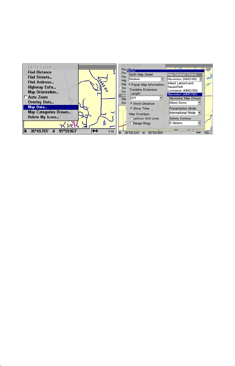
which display latitude and longitude grid lines or range rings on the
map. This menu lets you select Navionics Maps. For instructions, see
the Navionics Charts entry in this section.
To get to Map Data:
From the Map Page, press
MENU|↓ to MAP DATA|ENT.
Map Menu (left) and Map Data Menu (right).
Earth Map Detail
From the Map Page, press
MENU|↓ to MAP DATA|ENT. Press ENT to
check to select the level of map detail you prefer. Use ↑ ↓ to choose off,
low, medium or high, then press
EXIT to the page display.
Pop-up Map Info
From the Map Page, press
MAP INFO. With the option highlighted, press ENT to check it (turn on)
and uncheck it (turn off). After the option is set, press
MENU|↓ to MAP DATA|ENT. Press ↓ to POPUP
EXIT|EXIT to re-
turn to the page display.
Draw Map Boundaries
From the Map Page, press
DRAW MAP BOUNDARIES. With the option highlighted, press ENT to check it
MENU|↓ to MAP DATA|ENT. Press →|↓ to
(turn on) and uncheck it (turn off). After the option is set, press
EXIT|EXIT to return to the page display.
Fill Water with White
From the Map Page, press
WATER WITH WHITE. With the option highlighted, press ENT to check it
MENU|↓ to MAP DATA|ENT. Press →|↓ to FILL
(turn on) and uncheck it (turn off). After the option is set, press
EXIT|EXIT to return to the page display.
Trackline Extension
Trackline Extension is a new tracking option that provides a visual interpretation of your velocity. It charts how long it will take to travel a predetermined
distance based on your current navigational information. Distance is shown on
one side of the track with estimated time of arrival on the other. Below the
83
Page 92

Trackline Extension window are two check boxes (Show Time and Show Distance) which allow you to turn on or off the time and/or distance settings.
To set trackline extension: From the Map Page, press
DATA|ENT. Press ↓ to TRACKLINE EXTENSION|ENT. Use ↑ ↓ to select the desired
distance setting and press
ENT.
MENU|↓ to MAP
Presentation Mode
From the Map Page, press
PRESENTATION MODE|ENT. Use ↑ ↓ to choose the desired depth and press ENT.
MENU|↓ to MAP DATA|ENT. Press ↓ and → to
Presentation Mode gives you some control over the map layout by allowing you to choose between US and International Modes.
Safety Contour
From the Map Page, press
SAFETY CONTOUR|ENT. Use ↑ ↓ to choose the desired depth and press ENT. The
SAFETY CONTOUR command allows you to modify depth contours on a navionics
MENU|↓ to MAP DATA|ENT. Press ↓ and → to
map for water less than 10 meters deep. Based on your preferences, the
depth contours will be colored or shaded to make it easier to identify shallow
areas. Keep in mind the size of your ship's keel when determining which
option is right for your vessel.
Map Overlays (Range Rings; Lat/Long Grid)
The map screen can be customized with four range rings and/or grids that
divide the plotter into equal segments of latitude and longitude.
Range rings are handy for visually estimating distances on the map. The ring
diameters are based on the current zoom range. For example: at the 100-mile
zoom, the screen will show two rings with your current position in the center.
The large ring touching the left and right sides of the screen is 100 miles in
diameter (same as the zoom range). The second smaller ring is 50 miles in diameter (always 1/2 the zoom range).
The distance from your current position to the smaller ring (the ring's radius) is 25 miles (always 1/4 the zoom range). With the arrow keys and map
cursor, you can scroll the map to see the third and fourth rings. In this example, the distance to the third ring is 75 miles and distance to the fourth
ring is 100 miles from your current position.
To set range rings: From the Map Page, press
Press
↓ to RANGE RINGS. With the option highlighted, press ENT to check it (turn
on) and uncheck it (turn off). After the option is set, press
MENU|↓ to MAP DATA|ENT.
EXIT|EXIT to return
to the page display.
To set Lat/Long Grid: From the Map Page, press
DATA|ENT. Press ↓ to LAT/LON GRID LINES. With the option highlighted,
press
ENT to check it (turn on) and uncheck it (turn off). After the op-
tion is set, press
EXIT|EXIT to return to the page display.
MENU|↓ to MAP
84
Page 93
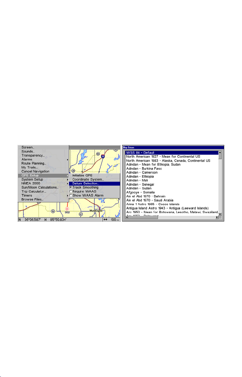
Map Datum Selection
Maps and charts are based on a survey of the area that's covered by the
map or chart. These surveys are called "Datums." Maps that are created using different datums will show the same latitude/longitude in
slightly different locations.
All datums are named. The GPS system is based on the WGS-84 datum, which covers the entire world. Other datums may also cover the
entire world, or just a small portion of it. By default, your position
shows using the WGS-84 datum. It, however, can show your position
using one of 191 different datums. To change the datum:
1. Press
2. Scroll
3. To return to the last page displayed, press
MENU|MENU|↓ to GPS SETUP|ENT|↓ to DATUM SELECTION|ENT.
↓ or ↑ to select the desired datum, then press ENT.
EXIT|EXIT.
A list of the datums used by this unit is in the back of this manual.
GPS Setup Menu (left) and Map Datum menu (right).
Map Detail Category Selection
This menu determines which of the mapping features are shown on the
screen. This includes waypoints, trails, icons, cities, highways, etc. You
can selectively turn on or off any of these items, customizing the map to
your needs.
To get to Map Categories:
1. From the Map Page, press
MENU|↓ to MAP CATEGORIES DRAWN|ENT.
2. Press
a subcategory. Press
↑ or ↓ to select a category or press → then press ↑ or ↓ to select
ENT to turn it off (no check) or on (checked).
3. To return to the last page displayed, press
85
EXIT|EXIT.
Page 94
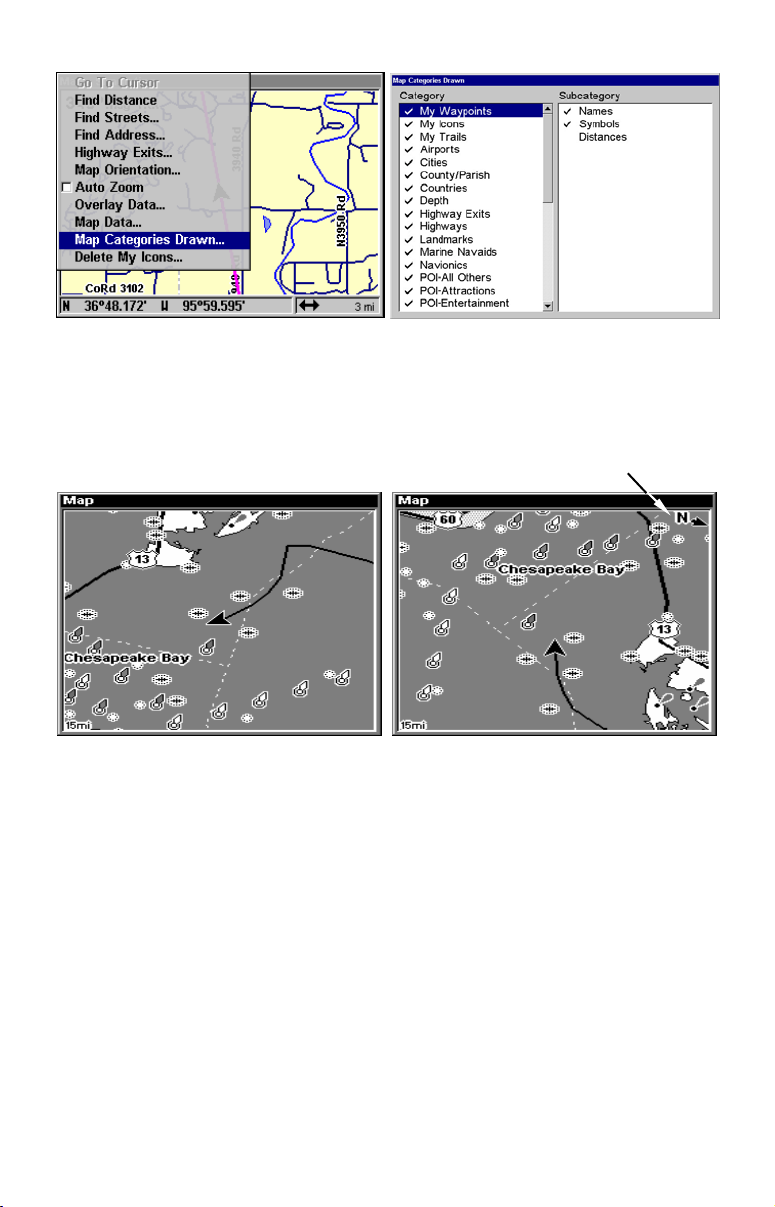
Map menu (left) and Map Categories Drawn menu (right).
Map Orientation
By default, this receiver shows the map with north always at the top of
the screen. This is the way most maps and charts are printed on paper.
This is fine if you're always traveling due north. What you see to your
left corresponds to the left side of the map, to your right is shown on
the right side of the map, and so on. If, however, you travel any other
direction, the map doesn't line up with your view of the world.
To correct this problem, a track-up mode rotates the map as you turn.
Thus, what you see on the left side of the screen should always be to
your left, and so on.
Another option is course-up mode, which keeps the map at the same
orientation as the initial bearing to the waypoint. When either the
track-up or course-up mode is on, a "N" is displayed on the map screen
to show you which direction is north.
In Track Up mode, map shows "N" and arrow to indicate north.
Map orientation shown in north up (left) and track up (right).
86
Page 95
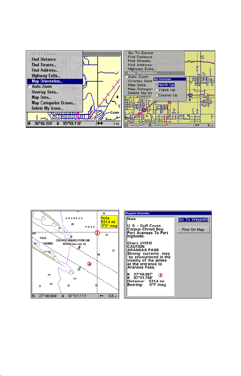
To change map orientation: from the Map Page, press
ORIENTATION|ENT. Use ↑ or ↓ to select the desired mode, then press ENT.
Press
EXIT|EXIT to return to the page display.
MENU|↓ to MAP
Map Menu (left) and Map Orientation menu with
the North Up map orientation option selected (right).
NauticPath™ USA Marine Charts
Your unit can display NauticPath electronic charts on MMCs. They
work just like a MapCreate custom map on a MMC.
Nautical Chart Notes
NauticPath charts contain notes or chart information, represented by
circle-i Chart Note icons on the map display. An example is shown in
the following figure.
NauticPath chart showing Chart Note icon selected by cursor (left).
Note information screen (right).
To view Chart Note information:
1. Use the arrow keys to move the cursor over a Chart Note icon. When
it's selected, a pop-up name box appears.
87
Page 96

2. Press
WPT to display the Note Information screen.
3. To scroll through the Chart Note screen, use ↑ ↓ arrow keys to read the
information. To return to the main page display, press
EXIT repeatedly.
Entrance to Aransas Pass on a NauticPath chart with 8-nautical mile
zoom (left). Remaining images (left to right): same position at 4-
nautical mile, 1-nautical mile and 0.3- nautical mile zoom ranges.
Port Information
NauticPath charts contain Port Services information, represented by
anchor icons on the map display. These icons will appear when you are
zoomed in to a 4-nautical mile range. An example is displayed in the
following figures.
To view Port Services information:
1. Use the arrow keys to move the cursor over a Port Services icon.
When it is selected, a pop-up name box appears.
2. Press
WPT to display the Port Services Information screen.
Pop-up
Port Services
icon
name box
NauticPath chart showing Port Services icon selected by cursor. When
first highlighted, the Pop-Up name box appears.
The Port Services information screen for a NauticPath chart contains
all the service information in one window.
88
Page 97

3. To scroll through the service information window, use ↑ ↓ to see the
types of services available. To return to the main page display, press
EXIT repeatedly.
Port Services information.
Tidal Current Information
NauticPath charts contain Tidal Current information,
represented at large zoom ranges by a box icon with the
letter "C." These icons will appear when you are zoomed
in to a 6-mile range. The icon stands for a Tidal Current
Station location. An example is displayed on the right.
When you zoom in to a sufficiently small zoom range (0.8 nautical
mile), the icon becomes an animated arrow showing tidal current velocity and direction for the selected tidal station at the present time. At
larger zoom ranges, you can select the boxed "C" icon and it becomes an
animated arrow with a pop-up name box (the name box disappears after a few seconds). Examples are displayed in the following figures.
To view Tidal Current information:
1. Use the arrow keys to move the cursor over a Tidal Current Station
icon. When it is selected, a pop-up name box appears.
2. Press
WPT to display the Tidal Current Information screen.
89
Page 98
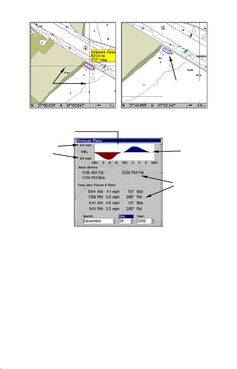
Cursor
lines
Tidal Current
Station icon in
animated mode
NauticPath chart showing Tidal Current Station icon selected by cur-
sor (left). Tidal Current animated icon at .8-nautical mile range.
Current Time Line
Velocity
Scale
Slack
Water
Line
Tide Tables
Current Information screen.
The Tidal Current Information screen displays daily tidal current data
for this station on this date at the present time. The graph at the top of
the screen is an approximate view of the flood and ebb pattern for the
day, from midnight (MN), to noon (NN) to midnight (MN). The velocity
scale at the top left side of the graph changes dynamically based upon
the maximum velocity of the current for that day.
Slack water, the period of little or no current, is represented by the
Slack Water Line (SWL). The flood appears above the SWL and the ebb
appears below the SWL. You can look up tidal current data for other
dates by changing the month, day and year selection boxes.
90
Page 99

To select another date:
1. Use ← → to highlight month, day or year, then press
2. Use ↑ ↓ to select the desired month, day or year and press
To clear the information screen, press
EXIT.
ENT.
ENT.
Tide Information
NauticPath charts contain Tidal Information, represented at large zoom ranges by a box icon with the
letter "T." These icons will appear when you are
zoomed in to a 6-mile range. The icon stands for a
Tidal Station location. An example is displayed at
right.
When you zoom in to a sufficiently small zoom range (0.8 nautical
mile), the icon becomes an animated gauge showing a rising or falling
tidal height for the selected station at the present time. At larger zoom
ranges, you can select the boxed "T" icon and it becomes an animated
gauge with a pop-up name box. The name box disappears seconds.
Tide Station
icon in animated mode
Cursor
lines
NauticPath chart showing Tide Station icon selected by cursor (left).
Icon animates automatically without selection at the 0.8-mile zoom
range (right). In the example above, the tide is at 0.9 feet and falling,
as shown by the down arrow at the top of the icon.
To view tide information:
1. Use the arrow keys to move the cursor over a tide station icon. When
it is selected, a pop-up name box appears.
2. Press
WPT to display the Tide Information screen.
91
Page 100
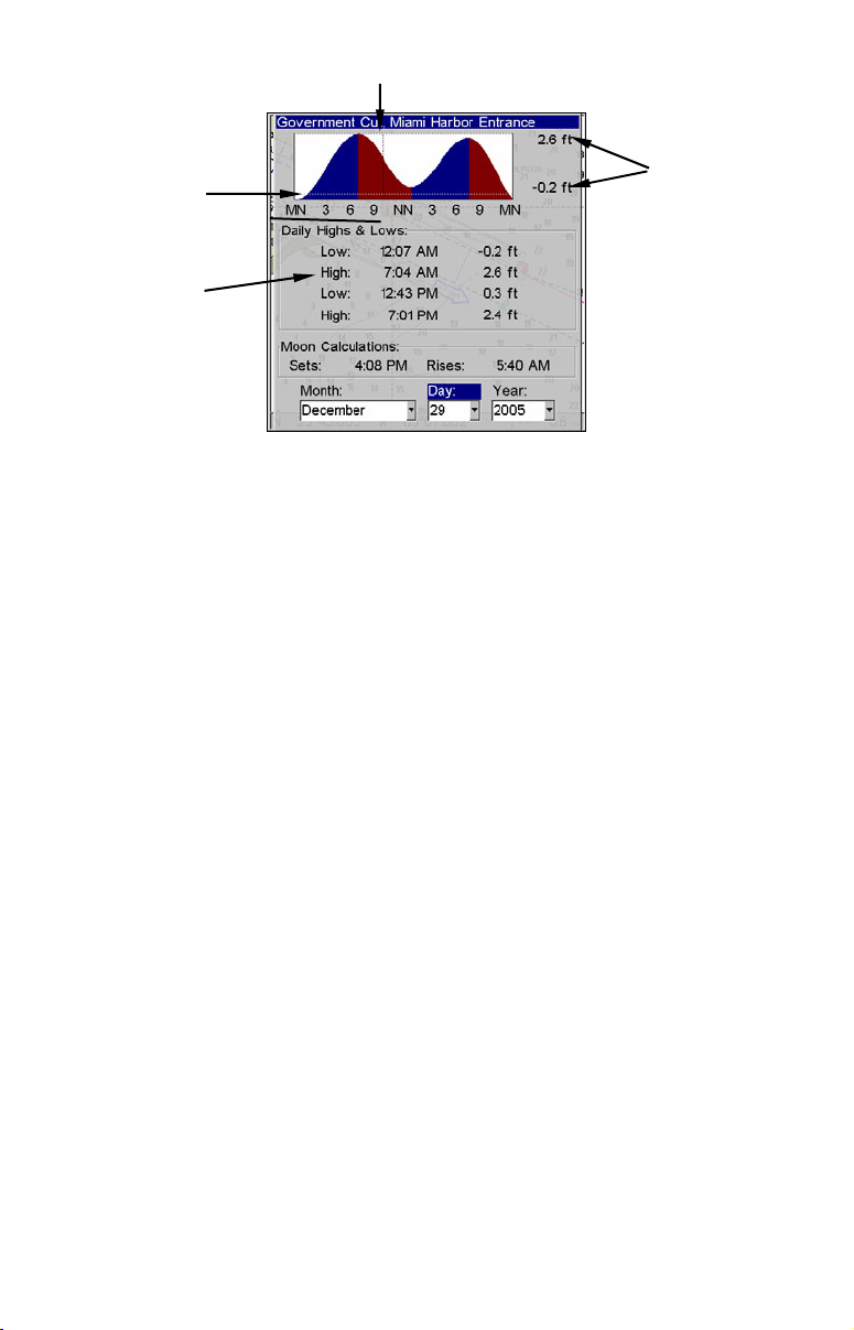
Current Time Line
MLLW
Line
Tide
Table
Height
Scale
Tide Information screen.
The Tide Information screen displays daily tidal data for this station on
this date at the present time. The graph at the top of the screen is an
approximate view of the tidal range pattern for the day, from midnight
(MN) to noon (NN) to midnight (MN). The dotted line across the graph
is the Mean Lower Low Water line (MLLW).
The height scale on the top right side of the graph changes, based upon
the maximum range of the tide for that day. The MLLW line also adjusts its position as the height scale changes.
You can look up tidal data for other dates by changing the month, day
and year selection boxes. To select another date:
1. Use ← → to highlight month, day or year, then press
ENT.
2. Use ↑ ↓ to select the desired month, day or year and press
To clear the information screen, press
EXIT.
ENT.
Navionics® Charts
Your unit can also display Navionics electronic charts on MMCs. Like
NauticPath, Navionics charts contain tide and port service information.
NOTE:
The primary operational difference between a NauticPath chart
and a Navionics chart is the way the chart data is set up for display. NauticPath charts are ready for display as soon as they are
inserted into the unit. Navionics charts must be inserted into the
unit, then selected as a Map Choice option in the Map Data menu.
92
 Loading...