

Page 1
Pub. 988-0154-641
EP-90R Pressure
Electronic Sensor
Installation and Configuration Instructions
This document shows how to install an EP-90R Pressure sensor and
how to connect it to a NMEA 2000
instructions on how to configure your pressure sensor with Lowrance
digital gauges (LMF-200 & LMF-400) and display units.
NMEA 2000 is the communication bus standard developed by the
National Marine Electronics Association (NMEA) for use in boats.
Lowrance has introduced a line of products that can communicate over
a NMEA 2000 network (LowranceNet).
All Lowrance NMEA 2000 capable devices are either NMEA 2000
certified or certification is pending.
CAUTION:
Installing LowranceNET NMEA 2000 devices is significantly
different from installing earlier Lowrance components without
NMEA 2000 features. You should read all of the installation
instructions before proceeding. Decide where you want to install
all components before drilling any holes in your vessel.
Some sonar or GPS display units may require a software upgrade to
display NMEA 2000 data correctly. For free software upgrades or
additional information on the LowranceNet NMEA 2000
system, visit our web site, www.lowrance.com.
®
network. It also provides
®
network
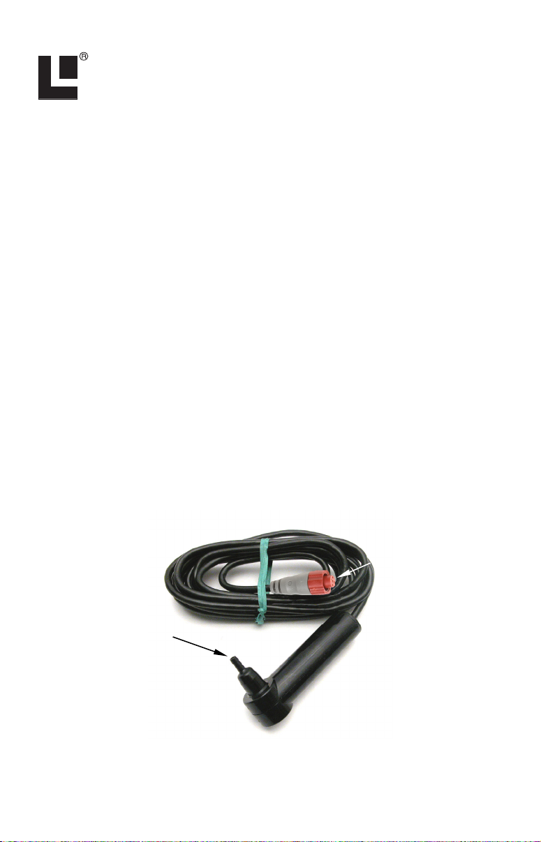
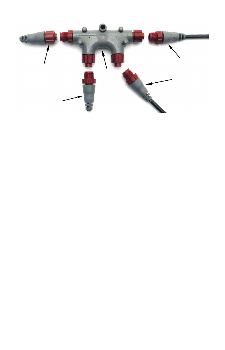
Red NMEA 2000
connector
Hose barb
attachment
EP-90R Pressure Sensor.
1
Page 2
The EP-90R consists of a red cable connector and the EP-90R housing
with standard size hose barb attachment.
The EP-90R Water Pressure sensor, like the other LowranceNet
Electronic Probe (EP) sensors, is designed for use with a NMEA 2000
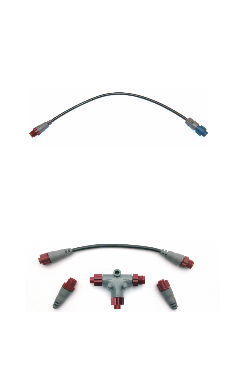
DeviceNet Network. Your sensor, however, is also compatible with
LowranceNet blue connector networks. It can be added to a blue
connector network by using a red female to blue female adapter cable.
Your sensor MUST be connected to a NMEA 2000 network or it WILL
NOT function.
The NMEA 2000 red female to blue female adapter cable allows users
to add red connector devices to a blue connector network.
Tools and Supplies
Your EP sensor packs with a T connector needed to attach it to a
LowranceNET NMEA 2000 network. If this is the first sensor you are
connecting, you may also need a one-time purchase of a LowranceNET
Node Kit.
The following tools and supplies are NOT included. Required tools
include: a utility knife. For some installations, a Phillips screwdriver
will be needed. Supplies include: zip/cable tie.
LowranceNET Node Kit for a NMEA 2000 network. Includes a 2-foot
extension cable, T connector and two 120-ohm terminators.
2
Page 3
For complete instructions on setting up a new NMEA 2000 network or
expanding an existing one, see the other document packed with your
EP-90R, "Setup and Installation of NMEA 2000 Networks, General
Information" part number 988-0154-173. If that document is not
available, it can be downloaded free from the Lowrance web site.
Installation
The EP-90R Pressure sensor can provide pressure data for the
following categories: Atmospheric Pressure, Engine Boost Pressure,
Engine Oil Pressure, Engine Water Pressure, Fuel Pressure,
Transmission Oil Pressure and Pitot Speed.
WARNING:
The maximum pressure for an EP-90R Pressure sensor is
100 PSI (689 kPa). If that pressure level is exceeded you
not only risk damaging the EP-90R, but could also suffer
bodily injury.
Pitot Tube (Water Speed)
We recommend installing the EP-90R near the boat’s original
speedometer.
NOTE:
If your engine does not have a speedometer hose, you will have to
purchase a pitot tube kit to use the EP-90R Pressure sensor. For
pitot tube installation instructions, refer to your pitot tube
installation manual.
The following steps cover the recommended installation of the EP-90R.
You will attach the EP-90R to a pitot tube hose in the same manner.
1. Remove the pressure hose from the boat’s speedometer.
2. Clip off the end of the pressure hose that was connected to the
speedometer. This will help ensure the pressure hose will fit snugly on
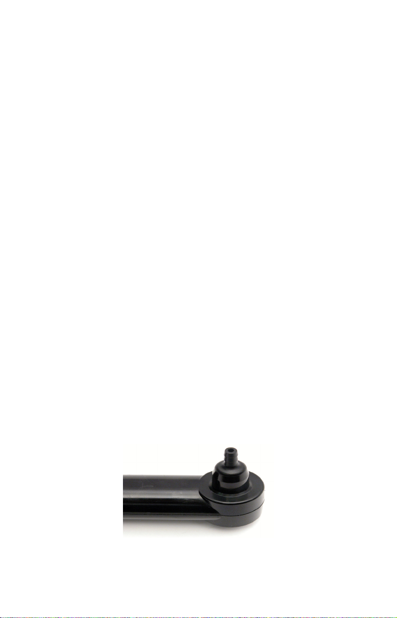
the EP-90R hose barb attachment. The hose-barb attachment
requires a 1.4" (6.35 mm) hose.
1/4 " hose barb attachment
3
Page 4

3. Slide the pressure hose onto the EP-90R hose barb attachment. If it
does not fit snugly, secure it with a zip tie at the base of the hose barb
attachment.
4. Now you are ready to remove the speedometer. Refer to the
speedometer’s installation manual for removal instructions.
5. The EP-90R is ready to be connected to NMEA 2000 network. If the
NMEA 2000 network backbone is in another part of the boat, the EP90R can be linked to the display unit at the console — if one is present
— or either of the LMF digital gauges by using the T connector that
was included in the packaging. If the network backbone is near the
console, connect the EP-90R red male connector to a T connector in the
desired location on the network backbone. The EP-90R is ready for use.
The rest of this document contains detailed information on connecting
to a NMEA 2000 network.
Installing the EP-90R to measure other data:
Follow this installation to monitor the following data: Atmospheric
Pressure, Engine Boost Pressure, Engine Oil Pressure, Engine Water
Pressure, Fuel Pressure and Transmission Oil Pressure.
NOTE:
Make sure the pressure hose has enough slack to be attached to the
pressure sensor when the EP-90R is connected to the NMEA 2000
backbone.
1. Slide the (Atmospheric, Engine Boost, Engine Oil, Engine Water,
Fuel or Transmission Oil) pressure hose onto the EP-90R hose barb
attachment. Attach a zip tie or hose clamp at the base of the hose barb
attachment.
2. The EP-90R is ready to be connected to NMEA 2000 network. If the
NMEA 2000 network backbone is in another part of the boat, the EP90R can be linked to the display unit at the console — if one is present
— or either of the LMF digital gauges by using the T connector that
was included in the packaging. If the network backbone is near the
console, connect the EP-90R red female connector to a T connector in
the desired location on the network backbone.
Connecting to a NMEA 2000 Network
A NMEA 2000 network is a communications link between two or more
devices that transfer NMEA 2000 information. A NMEA 2000 network
functions like the phone wiring in a house. If, for example, you pick up
a phone in the living room you will be able to hear the conversation
someone is having on a phone in the bedroom.
4
Page 5
In similar fashion, a NMEA 2000 network allows multiple display units
to receive data from a GPS antenna or multiple sonar units to receive
messages sent from a temperature sensor. A NMEA 2000 network
gives you the flexibility to view information like, engine diagnostics
and fuel level data on digital gauges or display units located anywhere
on your boat.
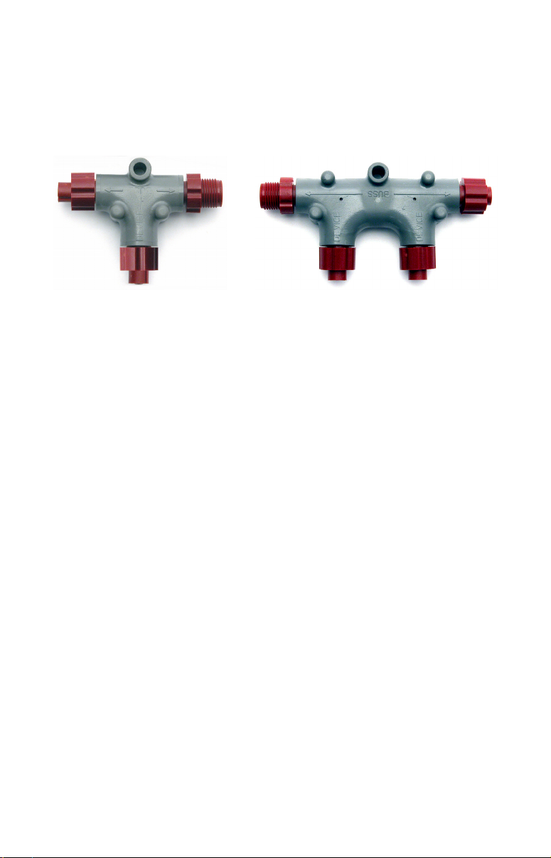
There are two types of LowranceNet red connectors: the single T
connector (left) and the double T connector (right).
Network Backbone and Network Nodes
A network bus backbone consists of network cabling, terminators and T
connectors. Network nodes are made by fitting T-shaped connectors into
the backbone (using the sockets on the sides) and attaching any network
device to the bottom of the T.
Staying with the previous phone wiring example, T connectors on the
backbone are the equivalent of phone jacks spread throughout a house.
To pick up a phone and be able to hear a conversation from another
phone in the house, both phones have to be connected to the main phone
line. In similar fashion, only sensors and display units plugged into the
NMEA network can share information.
The network backbone is like the phone wiring that runs throughout a
home. It connects the network nodes, allowing them to communicate
across the network. Connections found in the middle of the bus could have
T connectors or backbone network cable plugged into one or both sides.
Connections at the end of a network will have the backbone cable plugged
into one side and a terminator plugged into the other.
5
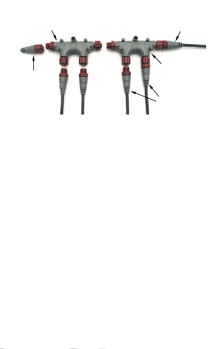
Page 6
Terminator at
the end of the
backbone (bus)
Cap for unused
connector
Double T
connector
Backbone cable
(to rest of bus)
Cable from
sensor or
display unit
NMEA 2000 network node located at the end of a NMEA 2000 backbone.
NOTE:
If you have a double T Connector on your network that is not
attached to a device, you must cap the unused connector with a
NMEA 2000 cap. This will protect the pin connectors from
corrosion. The NMEA 2000 cap looks like a terminator, but has
"Cap" stamped into the connector housing.
If you want to add another node to a working network, add another T
connector. T connectors may be purchased from LEI. If you are adding a
Lowrance or LEI NMEA 2000 sensor, it will come with its own T
connector.
Adding a Network Node
You can add a node to any existing connection, anywhere along the
network backbone. This connection could be between a T connector and a
terminator, between two T connectors, between a T connector and a
backbone extension cable or between two extension cables. Wherever you
want to add the new node, separate the sockets of the existing connection
and install the T connector between them.
If you want to add a node at the end of the backbone (network bus)
remove the terminator from the last connector. Install the new T
connector and attach the terminator to the side of the connector.
6
Page 7
Use T-connector or double T connector to add
device to bus (maintaining linear architecture)
Attach
terminator at
end of bus
In this example, a new device is added to the NMEA 2000 bus by
installing a T connector between a T connector and a terminator at the
end of the backbone (network bus).
Backbone cable
to rest of bus
Existing network
node
Devices connect to
double T connector
Additional Network Information
For more information on creating or expanding a network refer to the
NMEA 2000 network setup booklet, part number 988-0154-173, which
came packed with this document.
7
Page 8

Notes
8
Page 9
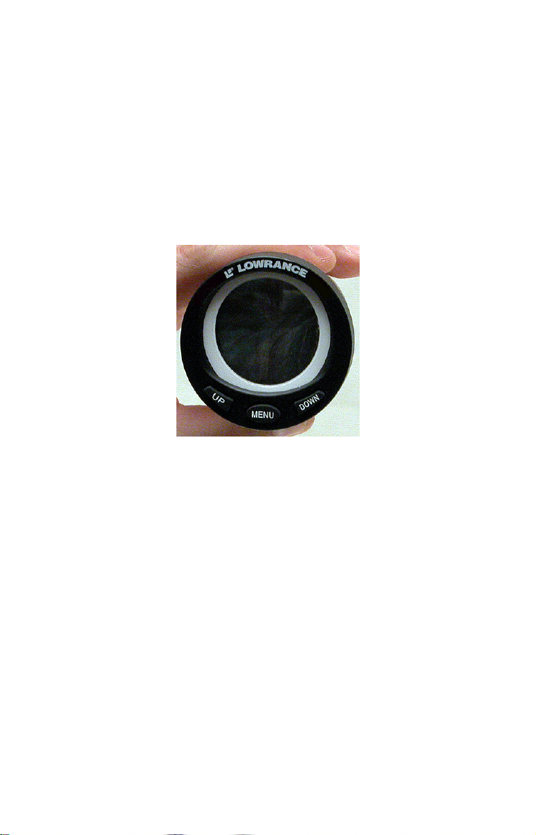
LMF-200: EP-90R
Pressure Configuration
This section covers how to use EP-90R Pressure Sensor with the LMF200 Multi-function gauge.
NOTE:
You will notice the LMF-200 does not have an Exit key. Menus will
time out after a preset amount of time (3, 5, 10 or 15 seconds). The
default setting is 5 seconds. Refer to your LMF-200 instruction
manual for more information on the Timeout feature.
LMF-200 Multi-function Digital Gauge.
Boat Setup
If this is the first time you have turned on your LMF-200, you will have
to complete Boat Setup before you will be able to configure your
pressure sensor.
To execute Boat Setup:
1. With Boat Setup highlighted on the screen, press MENU. The Boat
Setup menu will appear, allowing you to select an engine-tank
configuration that matches the number of engines and fuel tanks on
your vessel. Boat Setup options include: 1 En/1 Tk, 1 En/2 Tk, 2 En/1
Tk, 2 En/2 Tk, 3 En/1 Tk and 3 En/3 Tk.
2. Select the configuration option that matches number of engines and
tanks on your vessel and press
3. Select the tank you want to set up and press
the Tank Size window.
MENU.
MENU, which will open
9
Page 10

4. Use the
will hold and press
UP and DOWN keys to input the number of gallons the tank
MENU. Repeat steps 3 and 4 for each additional
tank. After all tanks have been set up, you will be directed to the main
display.
Boat Setup Reset
If you want to access the Setup screen (Boat Setup) after an enginetank configuration has been chosen you will have to reset the
configuration to default settings.
To reset engine tank configuration:
1. Press MENU, highlight SYSTEM SETUP and press MENU.
2. Choose
ENG/TANK and press MENU twice. The following message will
appear: Hit menu to reset Eng/Tnk.
3. Press
MENU. The Setup screen will appear with Boat Setup
highlighted.
EP-90R Pressure Configuration
Your EP-90R Pressure Sensor can be configured to measure the
following data types: Pitot Speed (PTT:S), Water Pressure (WTR:P),
Engine Oil Pressure (Eng:O:P), Fuel Pressure (FUL:P), Boost Pressure
(BST:P), Transmission Oil Pressure (Trn:O:P) and Atmospheric
Pressure (ATM:P).
To configure the EP-90R:
1. Press MENU, select SYSTEM SETUP and press MENU.
2. Highlight
pressure sensor (
will appear: Hit Menu to Cfg Pres Snsr.
3. Press
Pressure),
(Boost Pressure), TRN:O:P (Transmission Oil Pressure) or ATM:P
(Atmospheric Pressure) and press MENU. The Select Engine menu will
appear with up to three options. (If your unit is set to a single-tank
configuration, or if you chose Pitot Speed or Atmospheric Pressure, you
will be directed to the Bus Devices list.)
BUS DEVICES and press MENU. Select an unconfigured
UNCFG PRES) and press MENU. The following message
MENU, then select PTT:S (Pitot Speed), WTR:P (Engine Water
ENG:O:P (Engine Oil Pressure), FUL:P (Fuel Pressure), BST:P
4. Select the desired tank and press
the Bus Devices list.
10
MENU. You will be taken back to
Page 11

To unconfigure the EP-90R:
1. Press MENU, select SYSTEM SETUP and press MENU.
2. Highlight
sensor and press
3. The pressure sensor menu will appear. Highlight
MENU. The following message will appear: Hit Menu to Unset Dev
BUS DEVICES and press MENU. Select a configured pressure
MENU.
UNCONFIG and press
Name.
4. Press
To reconfigure the EP-90R:
MENU. You will be taken back to the Bus Devices list.
1. Press MENU, select SYSTEM SETUP and press MENU.
2. Highlight
sensor and press
3. The pressure sensor menu will appear. Highlight
MENU.
4. Select
BUS DEVICES and press MENU. Select a configured pressure
MENU.
RECONFIG and press
PTT:S (Pitot Speed), WTR:P (Engine Water Pressure), ENG:O:P
(Engine Oil Pressure), FUL:P (Fuel Pressure), BST:P (Boost Pressure),
TRN:O:P (Transmission Oil Pressure) or ATM:P (Atmospheric Pressure)
and press
MENU. The Select Engine menu will appear with up to three
options. (If your unit is set to a single-tank configuration, or if you
chose Pitot Speed or Atmospheric Pressure, you will be directed to the
Bus Devices list.)
4. Select the desired engine and press
MENU. You will be taken back to
the Bus Devices list.
Displaying Pressure Sensor Data
You can display pressure data on the Gauge, Single Digital, Dual
Digital and Fuel Manager pages.
Page Screen Rotation
The Page Screen Rotation consists of multiple pages that have been set
for display. Once pages have been added to the rotation, they can be set
to scroll across the screen automatically or manually. Press the
DOWN keys to manually scroll pages across the screen. Pressing the UP
key moves the scroll in one direction. Pushing the
DOWN key moves the
scroll in the other direction. You can use Autoscroll if you want the
pages to automatically scroll across the screen. Refer to your LMF -200
manual for information about Autoscroll.
11
UP and
Page 12

Adding a page:
1. Press MENU, use the UP and DOWN keys to select PAGES and press
MENU, which will open the Pages menu with the following options: Add
Page, Rem Page, Autoscroll and Set Pop-up.
2. Highlight
3. Select Gauge, Single Digital or Dual Digital and press
ADD PAGE and press MENU.
MENU. You
will be taken back to the main display, where the page you selected will
be shown.
Customizing Pages
The customizing pages feature allows you to choose what data will be
displayed and where it will be displayed on select pages. You can
customize the Gauge, Single Digital and Dual Digital pages with
pressure sensor data: Pitot Speed (PTT:S), Water Pressure (WTR:P),
Engine Oil Pressure (Eng:O:P), Fuel Pressure (FUL:P), Boost Pressure
(BST:P), Transmission Oil Pressure (Trn:O:P) and Atmospheric
Pressure (ATM:P).
To customize Gauge page:
1. After the Gauge page has been added to the page screen rotation, use
the
UP and DOWN keys to display it on the screen.
2. Press
3. Highlight
ENG:O:P (Engine Oil Pressure), FUL:P (Fuel Pressure), BST:P (Boost
Pressure),
Pressure) and press
MENU, select CUSTOMIZE and press MENU.
PTT:S (Pitot Speed), WTR:P (Engine Water Pressure),
TRN:O:P (Transmission Oil Pressure) or ATM:P (Atmospheric
MENU. If your unit is configured for multiple tanks,
the Select Engine menu will appear with up to three options. (If you
are using a single-tank configuration, or if you chose Pitot Speed or
Atmospheric Pressure, you will be directed to the main display.)
4. Highlight the desired tank and press
MENU. You will be taken back
to the main display.
To customize Single Digital page:
1. After the Single Digital page has been added to the page screen
rotation, use the
2. Press
MENU, select CUSTOMIZE and press MENU.
3. Highlight
ENG:O:P (Engine Oil Pressure), FUL:P (Fuel Pressure), BST:P (Boost
Pressure),
TRN:O:P (Transmission Oil Pressure) or ATM:P (Atmospheric
Pressure) and press
UP and DOWN keys to display it on the screen.
PTT:S (Pitot Speed), WTR:P (Engine Water Pressure),
MENU. The Select Engine menu will appear with
12
Page 13

up to three options. (If your unit is configured for one engine, or if you
chose Pitot Speed or Atmospheric Pressure, you will be directed back to
the main display.)
4. Select the desired engine and press
MENU. You will be taken back to
the main display.
To customize Dual Digital page:
1. After the Dual Digital page has been added to the page screen
rotation, use the
2. Press
MENU, select CUSTOMIZE and press MENU. The Position menu will
UP and DOWN keys to display it on the screen.
appear with two options: Top Data and Bottom Data.
3. Select the desired data position and press
4. Highlight
ENG:O:P (Engine Oil Pressure), FUL:P (Fuel Pressure), BST:P (Boost
Pressure),
Pressure) and press
PTT:S (Pitot Speed), WTR:P (Engine Water Pressure),
TRN:O:P (Transmission Oil Pressure) or ATM:P (Atmospheric
MENU. The Select Engine menu will appear with
MENU.
up to three options. (If your unit is configured for one engine, or if you
chose Pitot Speed or Atmospheric Pressure, you will be directed back to
the main display.)
5. Select the desired engine and press
MENU. You will be taken back to
the main display.
To customize Fuel Manager page:
1. After the Fuel Manager page has been added to the page screen
rotation, use the
2. Press
MENU, select CUSTOMIZE and press MENU.
3. Highlight
UP and DOWN keys to display it on the screen.
PTT:S (Pitot Speed) and press MENU. You will be taken
back to the main display.
Pressure Range (Gauge Page only)
From the analog page, you can set pressure ranges for Boost, Oil, Fuel
and Transmission Oil Pressure.
To set pressure range:
1. From the Gauge page, press MENU and select SYSTEM SETUP.
2. Highlight
Pressure menu with the following options: FUL:P (Fuel Pressure),
BST:P (Boost Pressure), WTR:P (Engine Water Pressure), Eng:O:P
(Engine Oil Pressure) and Trn:O:P (Transmission Oil Pressure).
13
PRES RNGS (Pressure Ranges), which will open the Select
Page 14

3. Select the desired option and press
MENU. The Pressure Range menu
will appear with the following options: 0-30 psi, 0-60 psi, 0-80 psi and
0-100 psi.
4. Select the desired PSI range and press
MENU.
Warning Threshold
When you set a Warning Threshold for a pressure sensor, a pop-up
window will appear and an alarm will sound when pressure exceeds a
preset pressure level of your choosing.
NOTE:
Warning Thresholds may be set to monitor Boost Pressure, Engine
Water Pressure, Oil Pressure, Fuel Pressure and Transmission Oil
Pressure.
To set a warning threshold:
1. Press MENU, select SYSTEM SETUP and press MENU.
2. Highlight
3. Select the desired pressure sensor and press
TRHLD and press MENU.
4. Use the
the
DOWN key to turn off a warning threshold. The threshold will be set
BUS DEVICES and press MENU.
MENU. Highlight WRNING
UP and DOWN keys to select the desired PSI level. Depress
to Off by default.
5. When the threshold is set to the desired level, press
MENU.
Reset
The reset command switches pressure sensor settings (alarms and
configuration) to default values.
To reset EP-90R values:
1. Press MENU, select SYSTEM SETUP and press MENU.
2. Highlight
sensor and press
3. The pressure sensor menu will appear. Highlight
MENU. The following message will appear: Press Menu to Rst Values.
You will be taken back to the Bus Devices list where the sensor will be
shown as PTT:S (Pitot Speed).
BUS DEVICES and press MENU. Select a configured pressure
MENU.
RESET and press
14
Page 15

LMF-400: EP-90R
Pressure Configuration
This section covers how to use your EP-90R Pressure Sensor with the
LMF-400 Multi-function gauge.
LMF-400 Multi-function Digital gauge.
Boat Setup
If this is the first time you have turned on your LMF-400, you will have
to complete Boat Setup before you will be able to configure your water
pressure sensor.
To execute Boat Setup:
1. With Boat Setup highlighted on the screen, press ENTER. A menu
will appear, allowing you to choose the number of engines and fuel
tanks on your vessel. The Boat Setup menu options are: 1 Eng/1 Tank,
1 Eng/2 Tank, 2 Eng/1 Tank, 2 Eng/2 Tanks, 3 Eng/1 Tank or 3 Eng/3
Tanks.
2. Use the
that applies to your vessel and press
engine/tank configuration, the Tank Size menu will appear with up to
three options (Port Tank, Center Tank and Starboard Tank), depending
on the engine tank configuration you chose. (If you selected one tank
during Boat Setup, you will be taken directly to the Setting Tank Size
Window in Step 4.)
3. Select the desired tank and press
Tank Size window.
4. Use the
will hold and press
of the remaining tanks.
UP and DOWN keys to select the engine-tank configuration
ENTER. After setting the
ENTER, which will open the Setting
UP and DOWN keys to input the number of gallons the tank
ENTER. Press EXIT and repeat steps 3 and 4 for each
15
Page 16

5. After all tanks on your vessel have been set up, press
EXIT repeatedly
to return to the main display.
Boat Setup Reset
If you want to access the Setup screen (Boat Setup) after an enginetank configuration has been chosen you will have to reset the
configuration to default settings.
To reset engine-tank configuration:
1. Press MENU, highlight SYSTEM SETUP and press ENTER.
2. Choose
ENG/TANK CFG and press ENTER twice. The following message
will appear: Press ENTER to reset Eng/Tnk Cfg.
3. Press
MENU. The Setup Menu will appear with Boat Setup
highlighted.
EP-90R Pressure Configuration
Your EP-90R Pressure Sensor can be configured to monitor the
following data: Pitot Tube, Engine Boost Pressure, Engine Oil
Pressure, Engine Water Pressure, Fuel Pressure, Transmission Oil
Pressure and Atmospheric Pressure.
To configure the EP-90R:
1. Press MENU, select SYSTEM SETUP and press ENTER.
2. Highlight
pressure sensor and press
BUS DEVICES and press ENTER. Select an unconfigured
ENTER. The following message will appear:
Press Enter to Configure Pressure Snsr.
3. Select
PRESSURE, TRNS OIL PRESS or ATM PRESSURE and press ENTER.
PITOT SPEED, ENG BST PRESS, ENG OIL PRESS, ENG WTR PRESS, FUEL
4. The Select Engine menu will appear with up to three options. (If
your unit is set to a single-engine configuration, or if you chose Pitot
Tube or Atmospheric Pressure, you will be taken back to the Bus
Devices list.)
5. Select the desired engine and press
ENTER. You will be directed to
the Bus Devices list.
To unconfigure the EP-90R:
1. Press MENU, select SYSTEM SETUP and press ENTER.
2. Highlight
sensor and press
3. Highlight
BUS DEVICES and press ENTER. Select a configured pressure
ENTER.
UNCONFIGURE and press ENTER. The following message will
appear: Press Enter to Unconfig Device Name.
16
Page 17

4. Press
EXIT repeatedly to return to the main display.
To reconfigure the EP-90R:
ENTER. You will be taken back to the Bus Devices list. Press
1. Press MENU, select SYSTEM SETUP and press ENTER.
2. Highlight
sensor and press
3. Highlight
4. Select the
PRESSURE, TRNS OIL PRESS or ATM PRESSURE and press ENTER. The Select
BUS DEVICES and press ENTER. Select a configured pressure
ENTER.
RECONFIGURE and press ENTER.
PITOT SPEED, ENG BST PRESS, ENG OIL PRESS, ENG WTR PRESS, FUEL
Engine menu will appear with up to three options. (If you are using a
single-engine configuration you will be taken back to the Bus Devices
list.)
5. Select the desired tank and press
the Bus Devices list. Press
EXIT repeatedly to return to the main
ENTER. You will be taken back to
display.
Displaying Pressure Sensor Data
You can display pressure sensor data on the Single Analog, Dual
Analog, Quad Analog, Single Digital, Dual Digital, Quad Digital and
Fuel Manager pages.
Page Screen Rotation
The Page Screen Rotation consists of multiple pages that have been set
up for display. Once pages have been added to the page screen rotation,
they can be set to scroll across the screen automatically or manually.
Use the
screen. Pressing the
Pushing the
use the Page Scrolling if you want pages to automatically scroll across
the screen. Refer to your LMF-400 manual for more information about
Page Scrolling.
To add a page to the display:
1. Press MENU, use the UP and DOWN keys to select PAGES and press
ENTER. A menu will pop up with four options: Add Page, Remove Page,
Page Scrolling and Pop-Ups Setup.
2. Select ADD PAGE and press ENTER.
3. Highlight Single Analog, Dual Analog, Quad Analog, Single Digital,
Dual Digital, Quad Digital or Fuel Manager and press
following message will appear: Press Enter to add the selected page.
4. Press
the page you selected will be shown on the screen.
17
ENTER and EXIT keys to manually scroll pages across the
ENTER key moves the scroll in one direction.
EXIT key moves the scroll in the other direction. You will
ENTER. The
ENTER, which will take you back to the main display, where
Page 18

Customizing Pages
The customizing pages feature allows you to choose what data will be
displayed on selected pages. You can use the Single Analog, Dual
Analog, Quad Analog, Single Digital, Dual Digital, Quad Digital pages
and Fuel Manager pages to display pressure sensor data.
To customize Single Analog page:
1. Make sure the Single Analog page has been added to the page screen
rotation.
2. Use the
ENTER and EXIT keys to scroll the Single Analog page onto
the main display.
3. Press
ENTER. The data menu will appear.
4. Select
PRESSURE, TRNS OIL PRESS or ATM PRESSURE and press ENTER. The Select
MENU, use the UP and DOWN keys to select CUSTOMIZE and press
PITOT SPEED, ENG BST PRESS, ENG OIL PRESS, ENG WTR PRESS, FUEL
Engine menu will appear with up to three options. (If your unit is set to
a single-engine configuration, or if you chose Pitot Speed or ATM
Pressure, you will be taken back to the Bus Devices list.)
5. Select the desired engine and press
the Bus Devices list. Press
EXIT repeatedly to return to the main
ENTER. You will be taken back to
display.
To customize Dual Analog page:
1. Make sure the Dual Analog page has been added to the page screen
rotation.
2. Use the
ENTER and EXIT keys to scroll the Dual Analog page onto the
main display.
3. Press
ENTER. The Position menu will appear with two options: Top Gauge
MENU, use the UP and DOWN keys to select CUSTOMIZE and press
and Bottom Gauge.
4. Select the desired position
and press ENTER. The data menu will
appear.
5. Highlight
PRESSURE, TRNS OIL PRESS or ATM PRESSURE and press ENTER. The Select
PITOT SPEED, ENG BST PRESS, ENG OIL PRESS, ENG WTR PRESS, FUEL
Engine menu will appear with up to three options. (If your unit is set to
a single-engine configuration, or if you chose Pitot Speed or ATM
Pressure, you will be taken back to the Position menu.)
6. Select the desired engine and press
ENTER. You will be directed to
the Position menu.
7. Repeat steps 4-6 to customize the other position or press
EXIT
repeatedly to return to the main display.
18
Page 19

To customize Quad Analog page:
1. Make sure the Quad Analog page has been added to the page screen
rotation.
2. Use the
ENTER and EXIT keys to scroll the Quad Analog page onto the
main display.
3. Press
MENU, select CUSTOMIZE and press ENTER. The Position menu
will appear with four options: Top Left, Top Right, Bottom Left and
Bottom Right.
4. Select the desired position and press ENTER. The data menu will
appear.
5. Highlight
PRESSURE, TRNS OIL PRESS or ATM PRESSURE and press ENTER. The Select
PITOT SPEED, ENG BST PRESS, ENG OIL PRESS, ENG WTR PRESS, FUEL
Engine menu will appear with up to three options. (If your unit is set to
a single-engine configuration, or if you chose Pitot Speed or ATM
Pressure, you will be taken back to the Position menu.)
6. Select the desired engine and press
ENTER. You will be directed to
the Position menu.
7. Repeat steps 4-6 to customize the other positions or press
EXIT
repeatedly to return to the main display.
To customize Single Digital page:
1. After the Single Digital page has been added to the page screen
rotation, use the
2. Press
ENTER. The data menu will appear.
MENU, use the UP and DOWN keys to select CUSTOMIZE and press
3. Highlight
PRESSURE, TRNS OIL PRESS or ATM PRESSURE and press ENTER. The Select
ENTER and EXIT keys to display it on the main screen.
PITOT SPEED, ENG BST PRESS, ENG OIL PRESS, ENG WTR PRESS, FUEL
Engine menu will appear with up to three options. (If your unit is set to
a single-engine configuration, or if you chose Pitot Speed or ATM
Pressure, you will be taken back to the main display.)
4. Select the desired engine and press
ENTER. You will be taken back to
the main display, where the data you selected will be shown.
To customize Dual Digital page:
1. After the Dual Digital page has been added to the page screen
rotation, use the
2. Press
ENTER. The Position menu will appear with two options: Top Data and
MENU, use the UP and DOWN keys to select CUSTOMIZE and press
ENTER and EXIT keys to display it on the main screen.
Bottom Data.
3. Highlight the desired data position and press
ENTER.
19
Page 20

5. Highlight
PRESSURE, TRNS OIL PRESS or ATM PRESSURE and press ENTER. The Select
PITOT SPEED, ENG BST PRESS, ENG OIL PRESS, ENG WTR PRESS, FUEL
Engine menu will appear with up to three options. (If your unit is set to
a single-engine configuration, or if you chose Pitot Speed or ATM
Pressure, you will be taken back to the Position menu.)
6. Select the desired engine and press
ENTER. You will be directed to
the Position menu.
7. Repeat steps 4-6 to customize the other position or press
EXIT
repeatedly to return to the main display.
To customize Quad Digital page:
1. After the Quad Digital page has been added to the page screen
rotation, use the
2. Press
ENTER. The Position menu will appear with four options: Data Box 1,
MENU, use the UP and DOWN keys to select CUSTOMIZE and press
ENTER and EXIT keys to display it on the main screen.
Data Box 2, Data Box 3 and Data Box 4.
3. Highlight the desired data position and press
5. Highlight
PRESSURE, TRNS OIL PRESS or ATM PRESSURE and press ENTER. The Select
PITOT SPEED, ENG BST PRESS, ENG OIL PRESS, ENG WTR PRESS, FUEL
ENTER.
Engine menu will appear with up to three options. (If your unit is set to
a single-engine configuration, or if you chose Pitot Speed or ATM
Pressure, you will be taken back to the Position menu.)
6. Select the desired engine and press
ENTER. You will be directed to
the Position menu.
7. Repeat steps 4-6 to customize the other positions or press
EXIT
repeatedly to return to the main display.
To customize Fuel Manager page:
1. After the Fuel Manager page has been added to the page screen
rotation, use the
2. Press
ENTER. The Position menu will appear with three options: Top Data,
MENU, use the UP and DOWN keys to select CUSTOMIZE and press
ENTER and EXIT keys to display it on the main screen.
Center Data and Bottom Data.
3. Highlight the desired data position and press
5. Highlight
6. Select the desired engine and press
PITOT SPEED and press ENTER.
ENTER. You will be directed to
ENTER.
the Position menu.
7. Repeat steps 4-6 to customize the other positions or press
EXIT
repeatedly to return to the main display.
20
Page 21

Pressure Range (Analog Pages only)
From the Single, Dual and Quad Analog pages, you can set pressure
ranges for Boost, Oil, Fuel and Transmission Oil Pressure.
To set pressure range:
1. From an analog page, press MENU, select SYSTEM SETUP and press
ENTER.
2. Highlight
PRESS RANGES (Pressure Ranges) and press ENTER. The
Select Pressure menu with the following options: Eng Water Pressure,
Eng Oil Pressure, Fuel Pressure, Eng Bst Press (Engine Boost
Pressure) and Trns Oil Press (Transmission Oil Pressure).
3. Select the desired option and press
ENTER. The Pressure Range
menu will appear with the following options: 0-15 psi, 0-30 psi, 0-60
psi, 0-80 psi and 0-100 psi.
4. Select the desired PSI range and press
ENTER.
Warning Threshold
When you set a Warning Threshold for a pressure sensor, a pop-up
window will appear and an alarm will sound when pressure exceeds a
preset pressure level of your choosing.
NOTE:
Warning Thresholds may be set to monitor Boost Pressure, Engine
Water Pressure, Oil Pressure, Fuel Pressure and Transmission Oil
Pressure.
To set a warning threshold:
1. Press MENU, select SYSTEM SETUP and press ENTER.
2. Highlight
3. Select the desired pressure sensor and press
4. Highlight
5. Use the
threshold. Press
6. Press
BUS DEVICES and press ENTER.
ENTER.
WRNG THRESHLD and press ENTER.
UP and Down KEYS to input the desired PSI level for the
ENTER. You will be taken back to the Bus Devices list.
EXIT repeatedly to return to the main display.
Reset Values
The Reset Values command switches pressure sensor settings (Alarms
and Configuration) to default values.
21
Page 22

To reset pressure sensor values:
1. Press MENU, select SYSTEM SETUP and press ENTER.
2. Highlight
3. Select the desired pressure sensor and press
4. Highlight
appear: Press Enter to Reset Values.
5. You will be taken back to the Bus Devices list. Press
to return to the main display.
BUS DEVICES and press ENTER.
ENTER.
RESET VALUES and press ENTER. The following message will
EXIT repeatedly
22
Page 23

Display Unit: EP-90R
Pressure Configuration
This section will show you how to use an EP-90R Pressure Sensor with
a display unit.
The LMS-525cDF is one of many Lowrance display units that may be
used with the EP-90R Pressure Sensor.
NOTE:
Your unit may have a NMEA 2000 menu or a Networking menu,
depending on the software version installed in your unit. Both
menus allow you to perform the same NMEA 2000-related
functions.
Bus Setup
Selecting Bus Setup from the NMEA 2000 or Networking menu will
open the Bus Configuration menu, giving you access to the EngineTank Configuration menu and the NMEA 2000 Devices list. The list,
located in the top half of the Bus Configuration menu, shows all devices
connected to the network. The Engine-Tank Configuration menu is
located in the bottom half of the Bus Configuration menu.
NOTE:
Some of the menus shown in this section may differ slightly from
the menus in your display unit, but your unit will perform the same
functions in a similar manner.
23
Page 24

Engine & Tank Configuration
The Engine-Tank configuration menu is located below the NMEA 2000
Devices list, but will only be accessible if engine- or fuel-related devices
are on the network.
When choosing an engine-tank configuration you will use the Tank
Select menu, Tank Size dialog box and Set Configuration button.
Bus Setup highlighted on the NMEA 2000 menu (left). Bus Setup
selected on Networking menu (right).
Setting Engine-Tank Configuration:
1. Press MENU twice, highlight NMEA 2000 or NETWORKING and press
ENTER.
2. The NMEA 2000 menu will appear with five options: Bus Setup,
Fuel Management, NMEA 2000 Alarms, Waypoint Sharing and
Backlight Synchronization. Choose
3. Select
ENGINE & TANK CONFIG and press ENTER, which will open the
Engine & Tank Configuration menu with the following configuration
options: 1 Engine/1 Tank, 1 Engine/2 Tanks, 2 Engines/1 Tank, 2
Engines/2 Tanks, 3 Engines/1 Tank, 3 Engine/3 Tanks and
Unconfigured Bus.
4. Choose the configuration that matches the number of engines and
tanks on your vessel and press
5. Highlight
TANK SELECT and press ENTER, which will open the Tank
Select menu.
6. Select the tank you want to set up and press
Tank Size dialog box and press
7. Input the capacity (gallons) of the tank you chose from the Tank
Select menu and press
ENTER.
8. Repeat Steps 5-7 for each remaining tank.
BUS SETUP and press ENTER.
ENTER.
ENTER. Highlight the
ENTER.
24
Page 25

9. When all tanks have been configured, highlight the
button and press
ENTER. The following confirmation message will
SET CONFIGURATION
appear: Are you sure you wish to change the bus configuration? Choose
YES and press ENTER, Press EXIT to return to the main display.
1 Engine/1Tank highlighted on Engine and Tank Configuration
menu (left). Starboard highlighted on Tank Select menu (center).
Tank Size set to 40 gallons (right).
9. When all tanks have been configured, highlight the SET CONFIGURATION
button and press
ENTER. The following confirmation message will
appear: Are you sure you wish to change the bus configuration? Choose
YES and press ENTER, Press EXIT to return to the main display.
EP-90R Pressure Sensor Configuration
The Location and Pressure Type menus will be used when configuring
you EP-90R. You can also change the sensor's Device Name.
Device Name
You can change how your pressure sensor will be displayed on your
unit's NMEA 2000 Devices list by inputting a customized device name
in the Device Name dialog box.
NOTE:
Changing the Device Name only will affect the way the EP-90R is
shown on your display unit. The customized device name will not
be seen by other devices or display units on the NMEA 2000
network.
To change Device Name:
1. Press MENU twice, select NMEA 2000 or NETWORKING and press ENTER.
2. Highlight
sensor from the Bus Devices list and press
3. Device Name will be highlighted. Press
Name dialog box.
25
BUS SETUP and press ENTER. Select the desired pressure
ENTER.
ENTER to access the Device
Page 26

4. Use the
have finished inputting the desired Device Name, press
EXIT repeatedly to return to the main display.
To reset device name to default setting:
UP and DOWN keys to change the Device Name. When you
ENTER. Press
1. Press MENU twice, select NMEA 2000 or NETWORKING and press ENTER. A
menu will appear with five options: Bus Setup, Fuel Management,
NMEA 2000 Alarms, Waypoint Sharing and Backlight
Synchronization.
2. Highlight
BUS SETUP and press ENTER, which will open the Bus
Configuration menu. A list of network devices will be at the top of the
page.
3. Select the pressure sensor with the device name you want to reset
and press
ENTER. The Device Configuration menu will appear with the
Device Name dialog box highlighted.
4. Press
disappears. Press
ENTER. Depress the left arrow key until the device name
ENTER, then press EXIT to return to the NMEA 2000
menu.
5. Highlight the device and press
ENTER. The Device Configuration
menu will open. The device name will be reset to its default setting.
Press
EXIT repeatedly to return to the main display.
To select Location:
1. Press MENU twice, select NMEA 2000 or NETWORKING and press ENTER. A
menu will appear with five options: Bus Setup, Fuel Management,
NMEA 2000 Alarms, Waypoint Sharing and Backlight
Synchronization.
2. Highlight
BUS SETUP and press ENTER, which will open the Bus
Configuration menu. A list of network devices will be at the top of the
page.
3. Select the desired pressure sensor and press
ENTER. The Device
Configuration menu will appear.
4. Highlight
LOCATION and press ENTER.
5. Select the desired location or the default (Unknown) and press
ENTER. The following message will appear: Are you sure you wish to
change this device's configuration?
6. Select
YES and press ENTER. Press EXIT repeatedly to return to the
main display.
26
Page 27

To select Pressure Type:
1. Press
MENU twice, select NMEA 2000 or NETWORKING and press ENTER. A
menu will appear with five options: Bus Setup, Fuel Management,
NMEA 2000 Alarms, Waypoint Sharing and Backlight
Synchronization.
2. Highlight
BUS SETUP and press ENTER, which will open the Bus
Configuration menu. A list of network devices will be at the top of the
page.
3. Select the desired pressure sensor and press
ENTER. The Device
Configuration menu will appear.
4. Highlight
PRESSURE TYPE and press ENTER. The following
configuration options will appear: Pitot Speed, Boost, Oil, Water, Fuel,
Transmission Oil, Atmospheric and the default setting, Unknown.
5. Highlight the desired Pressure Type and press
ENTER. The following
confirmation message will appear: Are you sure you wish to change this
device's configuration?
6. Highlight
YES and press ENTER. Press EXIT repeatedly to return to
the main display.
NOTE:
You can unconfigure your EP-90R by setting the Location and
Pressure Type to Unknown. You also can use the Restore Defaults
command.
Restore Defaults
The Restore Defaults command will reset your pressure sensor to
default settings.
To restore default settings:
1. Press
MENU twice, select NMEA 2000 or NETWORKING and press ENTER.
A menu will appear with five options: Bus Setup, Fuel Management,
NMEA 2000 Alarms, Waypoint Sharing and Backlight
Synchronization.
2. Highlight
BUS SETUP and press ENTER, which will open the Bus
Configuration menu. A list of network devices will be at the top of the
page.
3. Select the desired pressure sensor and press
ENTER. The Device
Configuration menu will appear.
4. Highlight
5. Select
ADVANCED OPTIONS and press ENTER.
RESTORE DEFAULTS and press ENTER. The following message will
appear: Are you sure you wish to change this device's configuration?
27
Page 28

6. Highlight
YES and press ENTER. Press EXIT repeatedly to return to
the main display.
NMEA 2000 Alarms
When you set a NMEA 2000 Alarm for a pressure sensor, a pop-up
window will appear and an alarm will sound when pressure exceeds or
falls below a preset PSI level of your choosing.
To turn on/off NMEA 2000 Alarm:
1. Press MENU twice, select NMEA 2000 or NETWORKING and press ENTER.
2. Highlight
3. Highlight
pressure sensor and press
4. Highlight the
or Low Pressure) and press
alarm is on an "X" will be placed in the Enabled Box.
5. To set the PSI level for an alarm, press → to highlight
press
ENT.
6. Use the arrow keys to input the desired PSI and press
Repeat Steps 3-4 to set the other alarm.
7. Highlight
settings. Press
NOTE:
To turn off (uncheck) an alarm, select its
ENTER. Highlight the SET CONFIGURATION button and press ENTER.
NMEA 2000 ALARMS and press ENTER.
FLUID LEVEL DEVICE and press ENTER. Select the desired
ENTER.
ENABLED box next to the desired alarm (High Pressure
ENTER to turn on the alarm. When the
VALUE and
ENTER.
SET CONFIGURATION and press ENTER to finalize alarm
EXIT repeatedly to get back to the main display.
ENABLED BOX and press
Alarm Status Tab
The Alarm Status tab is the second tab at the top of the NMEA 2000
Alarms page. When an alarm has been set for a device, the alarm and
its current status will be shown on the Alarm Status window.
To view Alarm Status:
1. Press MENU twice, select NMEA 2000 or NETWORKING and press ENTER.
2. Select
NMEA 2000 ALARMS and press ENTER.
3. Highlight the Alarm Status tab.
4. Press
EXIT repeatedly to return to the main display.
28
Page 29

Notes
29
Page 30

Notes
30
Page 31

LOWRANCE ELECTRONICS
FULL ONE-YEAR WARRANTY
"We," "our," or "us" refers to LOWRANCE ELECTRONICS, INC., the manufacturer of
this product. "You" or "your" refers to the first person who purchases this product as a
consumer item for personal, family or household use.
We warrant this product against defects or malfunctions in materials and workmanship,
and against failure to conform to this product's written specifications, all for one (1) year
from the date of original purchase by you. WE MAKE NO OTHER EXPRESS
WARRANTY OR REPRESENTATION OF ANY KIND WHATSOEVER CONCERNING
THIS PRODUCT. Your remedies under this warranty will be available so long as you can
show in a reasonable manner that any defect or malfunction in materials or
workmanship, or any non-conformity with the product's written specifications, occurred
within one year from the date of your original purchase, which must be substantiated by
a dated sales receipt or sales slip. Any such defect, malfunction, or non-conformity which
occurs within one year from your original purchase date will either be repaired without
charge or be replaced with a new product identical or reasonably equivalent to this
product, at our option, within a reasonable time after our receipt of the product. If such
defect, malfunction, or non-conformity remains after a reasonable number of attempts to
repair by us, you may elect to obtain without charge a replacement of the product or a
refund for the product. THIS REPAIR, OR REPLACEMENT OR REFUND (AS JUST
DESCRIBED) IS THE EXCLUSIVE REMEDY AVAILABLE TO YOU AGAINST US FOR
ANY DEFECT, MALFUNCTION, OR NON-CONFORMITY CONCERNING THE
PRODUCT OR FOR ANY LOSS OR DAMAGE RESULTING FROM ANY OTHER
CAUSE WHATSOEVER. WE WILL NOT UNDER ANY CIRCUMSTANCES BE LIABLE
TO ANYONE FOR ANY SPECIAL, CONSEQUENTIAL, INCIDENTAL, OR OTHER
INDIRECT DAMAGE OF ANY KIND.
Some states do not allow the exclusion or limitation of incidental or consequential
damages, so the above limitations or exclusions may not apply to you.
This warranty does NOT apply in the following circumstances: (1) when the product has
been serviced or repaired by anyone other than us; (2) when the product has been
connected, installed, combined, altered, adjusted, or handled in a manner other than
according to the instructions furnished with the product; (3) when any serial number has
been effaced, altered, or removed; or (4) when any defect, problem, loss, or damage has
resulted from any accident, misuse, negligence, or carelessness, or from any failure to
provide reasonable and necessary maintenance in accordance with the instructions of the
owner's manual for the product.
We reserve the right to make changes or improvements in our products from time to time
without incurring the obligation to install such improvements or changes on equipment or
items previously manufactured.
This warranty gives you specific legal rights and you may also have other rights which
may vary from state to state.
REMINDER: You must retain the sales slip or sales receipt proving the date of your
original purchase in case warranty service is ever required.
LOWRANCE ELECTRONICS
12000 E. SKELLY DRIVE, TULSA, OK 74128
(800) 324-1356
31
Page 32

How to Obtain Service…
…in the USA:
Contact the Factory Customer Service Department. Call toll-free:
For Lowrance: 800-324-1356. For Eagle: 800-324-1354
8 a.m. to 5 p.m. Central Standard Time, M-F
Lowrance Electronics and Eagle Electronics may find it necessary to change or end
their shipping policies, regulations and special offers at any time. They reserve the
right to do so without notice.
…in Canada:
Contact the Factory Customer Service Department. Call toll-free:
800-661-3983
905-629-1614 (not toll-free)
8 a.m. to 5 p.m. Eastern Standard Time, M-F
…outside Canada and the USA:
Contact the dealer in the country where you purchased your unit. To locate a
dealer near you, see the instructions in paragraph number 1 below.
Accessory Ordering Information
LEI Extras™, Inc. is the accessory source for sonar and GPS products
manufactured by Lowrance Electronics and Eagle Electronics. To order
Lowrance or Eagle accessories, please contact:
1) Your local marine dealer or consumer electronics store. To locate a Lowrance
dealer, visit the web site, www.lowrance.com, and look for the Dealer Locator.
To locate an Eagle dealer, visit the web site, www.eaglesonar.com, and look for
the Dealer Locator. Or, consult your telephone directory for listings.
2) U.S. cus+tomers: LEI Extras Inc., PO Box 129, Catoosa, OK 74015-0129
Call toll free in the U.S., 800-324-0045, 8 a.m. to 5 p.m. Central
Standard Time, M-F, or visit our web site www.lei-extras.com.
3) Canadian customers: Lowrance/Eagle Canada, 919 Matheson Blvd. E.
Mississauga, Ontario L4W2R7 or fax 905-629-3118.
Call toll free in Canada, 800-661-3983, or dial 905 629-1614 (not toll free), 8
a.m. to 5 p.m. Eastern Standard Time, M-F.
For Lowrance® and Eagle® Products
Pub. 988-0154-641 © Copyright 2007
All Rights Reserved
Printed in USA 091807 Lowrance Electronics, Inc.
32
 Loading...