

Page 1
Pub. 988-0154-432
EP-60R Fuel Flow
Electronic Sensor
Installation, Configuration and Calibration Instructions
This document shows how to install an EP-60R Fuel Flow sensor and
how to connect it to a NMEA 2000
instructions on how to configure and calibrate your fuel flow sensor
with Lowrance digital gauges (LMF-200 & LMF-400) and display units.
NMEA 2000 is the communication bus standard developed by the
National Marine Electronics Association (NMEA) for use in boats.
Lowrance has introduced a line of products that can communicate over
a NMEA 2000 network (LowranceNet).
All Lowrance NMEA 2000 capable devices are either NMEA 2000
certified or certification is pending.
Caution:
Installing LowranceNET NMEA 2000 devices is significantly
different from installing earlier Lowrance components without
NMEA 2000 features. You should read all of the installation
instructions before proceeding. You should decide where to
install all components before drilling any holes in your vessel.
®
network. It also provides
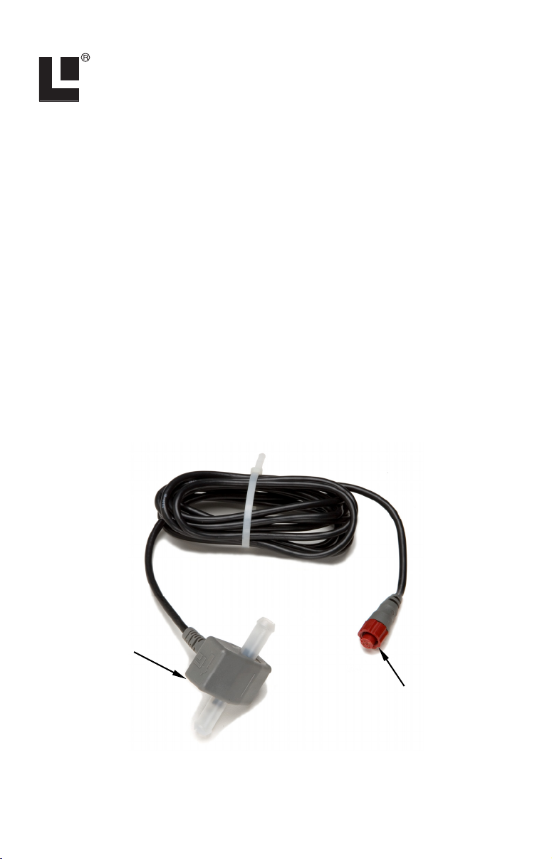
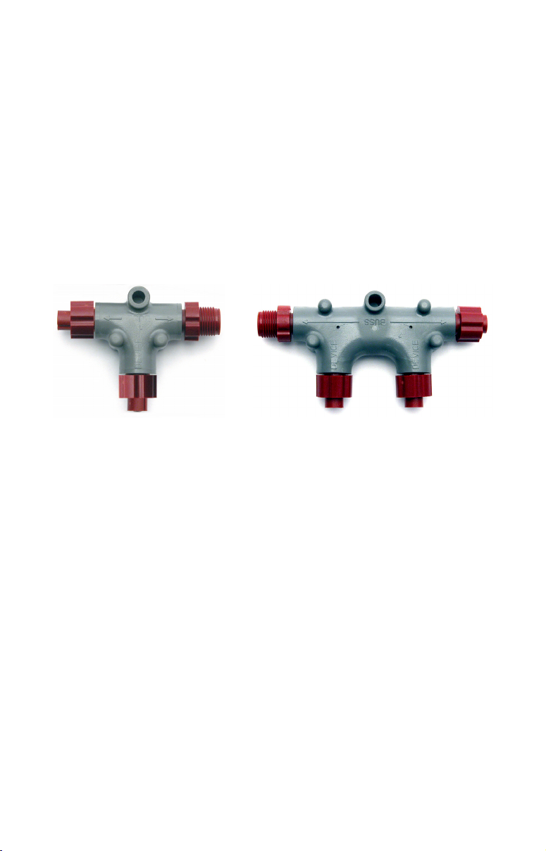
Fuel Flow
module
NMEA 2000
red connector
The EP-60R Fuel Flow sensor.
1
Page 2
Some sonar or GPS display units may require a software upgrade to
display NMEA 2000 data correctly. For free software upgrades or
additional information on the LowranceNet NMEA 2000
®
network
system, visit our web site, www.lowrance.com.
The EP-60R consists of a red cable connector and the sensor module.
The sensor module contains a turbine to measure fuel flow and
electronics which convert flow data to the NMEA 2000 data format.
The cable length from the connector to the smart module is 10 feet (3
meters). The sensor is designed to work with gasoline only.
WARNING:
Do not use this sensor with diesel engine fuel systems.
The EP-60R is designed only for gasoline engines.
This sensor has been optimized to measure flow rates between 0.6 to 45
gallons (US) per hour, but it will operate at flow rates outside that
range. The sensor will add 0.5 PSI of back pressure on the fuel system
with a flow rate of 20 gallons per hour. At the rate of 40 gallons per
hour, the back pressure will be 1 PSI.
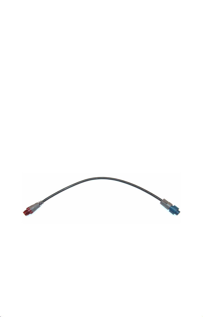
The EP-60R Fuel Flow, like the other LowranceNet Electronic Probe
(EP) sensors, is designed for use with a NMEA 2000 network. Your
sensor, however, is also compatible with LowranceNet blue connector
networks. It can be added to a blue connector network by using a
female red to female blue adapter cable. Your sensor MUST be
connected to a NMEA 2000 network or it WILL NOT function.
The NMEA 2000 female red to female Blue adapter cable allows users
to add red connector devices to a blue connector network.
Tools and Supplies
Your EP sensor packs with a T connector needed to attach it to a
LowranceNET NMEA 2000 network. If this is the first sensor you are
connecting, you may also need to purchase of a LowranceNET Node
Kit.
2
Page 3
LowranceNET Node Kit for a NMEA 2000 network. Includes a 2-foot
extension cable, T connector and two 120-ohm terminators.
For complete instructions on setting up a new NMEA 2000 network or
expanding an existing one, see the other document packed with your
EP-60R Fuel Flow, "Setup and Installation of NMEA 2000 Networks,
General Information" part number 988-0154-173. If that document is
unavailable, it can be downloaded free from the Lowrance web site.
Other supplies are not included, unless otherwise indicated. Required
supplies include cable ties or other fasteners to secure the hose and
cable; an inline fuel filter and any items needed to install it. Two 1"
hose clamps are included with the sensor.
We assume you already have a fuel line installed. The EP-60R Fuel
Flow was designed to fit a typical 3/8" SAE USCG Type A1 fuel hose. If
your engine has different diameter hoses or metal fuel lines, a section
of 3/8" fuel line must be installed between the sensor and the existing
lines. Recommended tools are a flathead screwdriver to tighten the
clamps and a knife to cut the fuel hose. If you need to route the sensor
connector through a bulkhead, you will need a drill and a 3/4" drill bit.
Installation
Install one EP-60R sensor per engine. If you have multiple tanks, place
the sensor after any Y or T in the line feeding the engine.
The sensor should be installed vertically, as close as possible to the fuel
tank in an area where vibration is minimized. The housing has a
molded-in, fuel flow direction arrow, which should be pointing up.
Mount the sensor above the tank's maximum fuel level to avoid
accidental fuel leakage in case the sensor becomes disconnected.
Caution:
Gasoline is extremely flammable. If possible, drain the fuel line
before you start or shut any flow valves located at the tank. Keep
sparks and flame away from the work area. After installation,
remember to clean up any spilled fuel.
3
Page 4
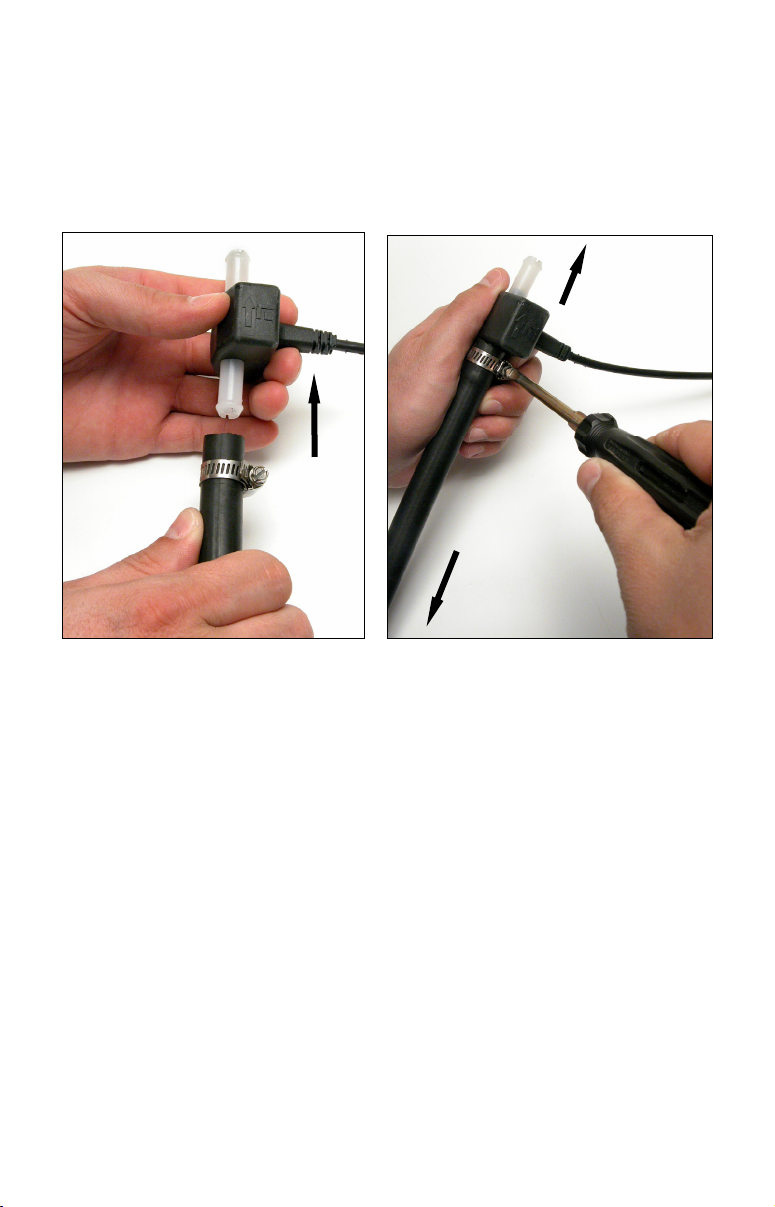
Cut the fuel hose where you intend to install the EP-60R sensor. Slide
a clamp over the hose coming from the tank, then push the hose onto
the bottom (inlet) hose barb.
Seat the hose flush against the sensor housing, then tighten the hose
clamp. Attach the hose leading to the engine on the top (outlet) barb in
the same way.
To
engine
Flow
direction
From
tank
Push the fuel line onto the hose barb, then tighten the hose clamp.
Orient the sensor vertically, with the flow arrow pointing up.
NOTE:
You must install an in-line fuel filter between the tank and the EP60R sensor. This will prevent a malfunction caused by
contaminated fuel. Debris in unfiltered fuel can clog the sensor's
turbine and result in rough performance or engine shut down.
As with any fuel system, we recommend you always carry onboard
a spare fuel filter and an in-line 3/8" splice barb. This allows you to
remove a clogged EP-60R fuel sensor or fuel filter and restore
engine operation if the fuel filter fails. We strongly recommend that
you inspect your entire fuel system at regular intervals.
Secure the sensor/hose assembly so the sensor remains in a vertical
position with the flow direction up. Clamp the hose on either side of the
sensor to the hull or bulkhead to minimize vibration.
Route the sensor's cable connector to the T on the network backbone
where you intend to attach it, and plug it in. The sensor is ready to use.
4
Page 5
Connecting to a NMEA 2000 Network
A NMEA 2000 network is a communications link between two or more
devices that transfer NMEA 2000 information. LowranceNET is the
NMEA 2000 networking system developed by Lowrance Electronics. A
NMEA 2000 network functions like the phone wiring in a house.
If, for example, you pick up a phone in the living room you will be able
to hear the conversation someone is having on a phone in the bedroom.
In similar fashion, a NMEA 2000 network allows multiple display units
to receive data from a GPS antenna or multiple sonar units to receive
messages sent by a temperature sensor. A NMEA 2000 network gives
you the flexibility to view information like engine diagnostics and fuel
level data on digital gauges or display units located anywhere on your
boat.
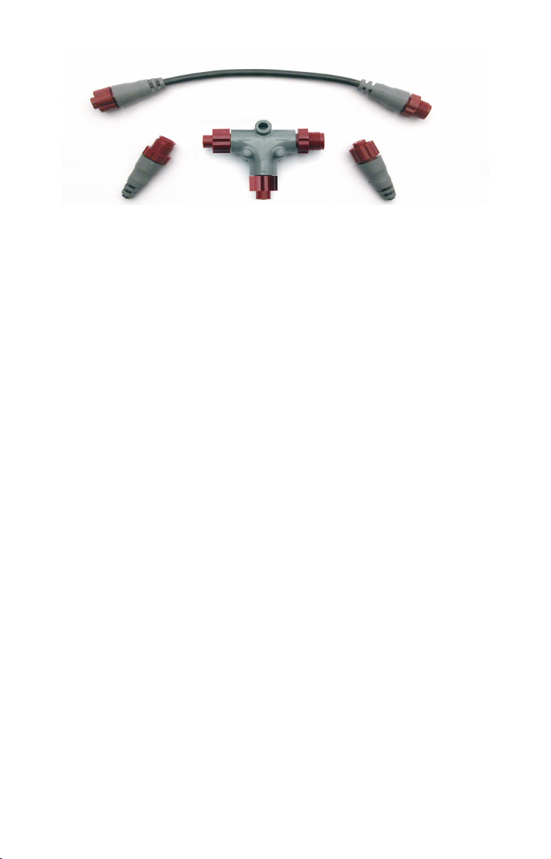
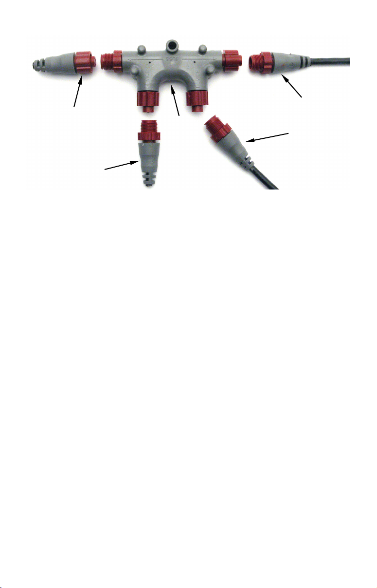
There are two types of LowranceNet red connectors: the single T
connector (left) and the double T connector (right).
Network Backbone and Network Nodes
A network bus backbone consists of network cabling, terminators and T
connectors. Network nodes are made by fitting T-shaped connectors into
the backbone (using the sockets on the sides) and attaching any network
device to the bottom of the T.
Staying with the previous phone wiring example, T connectors on the
backbone are the equivalent of phone jacks spread throughout a house.
To pick up a phone and be able to hear a conversation from another
phone in the house, both phones have to be connected to the main phone
line. In similar fashion, only sensors and display units plugged into the
NMEA network can share information. The network backbone is like the
phone wiring that runs throughout a home.
It connects the network nodes, allowing them to communicate across the
network. Connections found in the middle of the bus could have T
connectors or backbone network cable plugged into one or both sides.
Connections at the end of a network will have the backbone cable plugged
into one side and a terminator plugged into the other, as shown in the
following figure.
5
Page 6
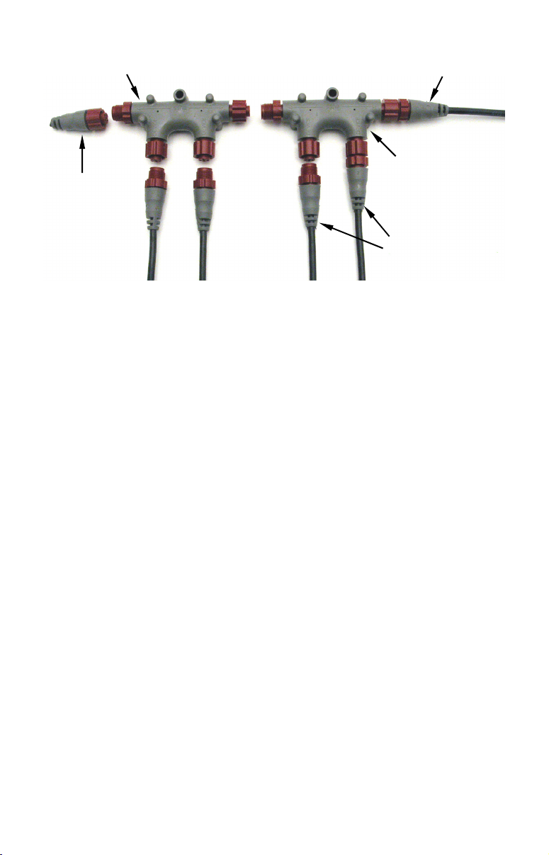
Terminator at
the end of the
backbone (bus)
Cap for unused
connector
Double T
connector
Backbone cable
(to rest of bus)
Cable from
sensor or
display unit
NMEA 2000 network node located at the end of a NMEA 2000 backbone.
NOTE:
If you have a double T Connector on your network that is not
attached to a device, you must cap the unused connector with a
NMEA 2000 cap. This will protect the pin connectors from
corrosion. The NMEA 2000 cap looks like a terminator, but has
"Cap" stamped into the connector housing.
All T connectors on your network probably will be connected to a device.
If you want to add another node to a working network, add another T
connector. T connectors may be purchased from LEI (ordering
information appears on the back page of this booklet). If you are adding a
Lowrance or LEI NMEA 2000 sensor, it will come with a T connector.
Adding a Network Node
You can add a node to any existing connection, anywhere along the
network backbone. This connection could be between a T connector and a
terminator, between two T connectors, between a T connector and a
backbone extension cable or between two extension cables. Wherever you
want to add the new node, separate the sockets of the existing connection
and install the T connector between them. If you want to add a node at
the end of the backbone (network bus) remove the terminator from the
last connector, like the figure above. Install the new T connector and
attach the terminator to the side of the connector.
6
Page 7
Use T-connector or double T connector to add
device to bus (maintaining linear architecture)
Attach
terminator at
end of bus
In this example, a new device is added to the NMEA 2000 bus by
installing a T connector between a T connector and a terminator at the
end of the backbone (network bus).
Backbone cable
to rest of bus
Existing network
node
Devices connect to
double T connector
Additional Network Information
For more information on creating or expanding a network refer to the
NMEA 2000 network setup booklet, part number 988-0154-173, which
came packed with this document.
7
Page 8

Notes
8
Page 9
LMF-200: EP-60R
Configuration & Calibration
This section covers how to use the EP-60R Fuel Flow with a LMF-200
Multi-function gauge.
NOTE:
You will notice the LMF-200 does not have an Exit key. Menus will
time out after a preset amount of time (3, 5, 10 or 15 seconds). The
default setting is 5 seconds. Refer to your LMF-200 instruction
manual for more information on the Timeout feature.
LMF-200 Multi-function Digital Gauge
Boat Setup
If this is the first time you have turned on your LMF-200, you will have
to complete Boat Setup before you will be able to configure or calibrate
your fuel flow. If you have already completed Boat Setup, skip ahead to
the segment covering EP-60R Fuel Flow Configuration.
To execute Boat Setup:
1. With Boat Setup highlighted on the screen, press MENU. The Boat
Setup menu will appear, allowing you to select an engine-tank
configuration to match the number of engines and fuel tanks on your
vessel. Boat Setup options include: 1 En/1 Tk, 1 En/2 Tk, 2 En/1 Tk, 2
En/2 Tk, 3 En/1 Tk and 3 En/3 Tk.
2. Select the correct configuration option and press
selected a configuration with more than one tank, the Tank Size menu
will appear. (If you selected a single tank configuration you will be
taken directly to the Tank Size window, where you can input the size of
the tank.)
9
MENU. If you
Page 10

3. Select the tank you want to set up and press
MENU, which will open
the Tank Size window.
4. Use the
will hold and press
UP and DOWN keys to input the number of gallons the tank
MENU. Repeat steps 3 and 4 for each additional
tank. After all tanks have been set up, you will be directed to the main
display.
Boat Setup Reset
If you want to access the Setup screen (Boat Setup) after an enginetank configuration has been chosen you will have to reset the
configuration to default settings.
To reset engine tank configuration:
1. Press MENU, highlight SYSTEM SETUP and press MENU.
2. Choose
ENG/TANK and press MENU twice. The following message will
appear: Hit menu to reset Eng/Tnk.
3. Press
MENU. The Setup screen will appear with Boat Setup
highlighted.
Fuel Remaining Source (FRem Src)
The Fuel Remaining source function allows you to select the device
used to measure the amount of fuel remaining in the tank. It will be set
to fluid level by default.
To set Fuel Remaining Source to Fuel Flow (Eng/FFlow):
1. Press MENU, use the UP and DOWN keys to select SYSTEM SETUP and
press
MENU. Select FUEL MNGR and press MENU.
2. Highlight
FREM SRC and press MENU. That will open the FRem Src
menu, which has two options: Eng/FFlow and Fuel level.
3. Select
ENG/FFLOW and press MENU. You can now view fuel remaining
data from the EP-60R.
EP-60R Fuel Flow Configuration
The LMF-200 can support up to three engines with one fuel flow sensor
for each engine. Each fuel flow has an internal menu with the following
options: Unset Engine, Change Engine (multiple engines only), Fuel
Warning, Reset and Reset Calibration.
To configure a fuel flow:
1. Press MENU, use the UP and DOWN keys to select SYSTEM SETUP and
press
MENU.
2. Highlight
Devices list will appear.
10
B. DEVICES and press MENU. After a few moments, the Bus
Page 11

3. Select
Hit Menu to Cfg Flow Sns. Press
UNCFG FF and press MENU. The following message will appear:
MENU and the Configuration options
menu will appear.
NOTE:
If your unit is set to a single-engine configuration, the
Configuration Options menu will not appear when you are
configuring a fuel flow. The fuel flow will automatically be
configured as Eng FFlow.
4. Select the desired option and press
MENU. You will be directed to the
Bus Devices list. Configure remaining fuel flows by following the steps
above.
To unconfigure a fuel flow:
You will use the Unset Engine command when you want to unconfigure
a fuel flow.
To unset engine:
1. Press
press
2. Highlight
MENU, use the UP and DOWN keys to select SYSTEM SETUP and
MENU.
B. DEVICES and press MENU. After a few moments, the Bus
Devices list will appear.
3. Select the fuel flow you want to unconfigure and press
4. Highlight
following message: Hit Menu to Unset Dev Name.
UNSET ENGINE and press MENU which will launch the
MENU.
5. Press MENU and you will be taken back to the Bus Devices list. The
newly unconfigured fuel flow will be displayed as
To reconfigure a fuel flow:
UNCFG FF.
You will use the Change Engine command to reconfigure a Fuel Flow.
Change Engine, however, will only appear on your LMF-200 menu if
you have more than one engine. If you want to reconfigure a fuel flow,
but all the fuel flows on your vessel are configured, you first will have
to unconfigure a fuel flow to free up its configuration name.
If all three fuel flows are configured, which means there is no name
configuration available, follow the first set of instructions. If the desired
configuration name is available, follow the second set of instructions.
Change Engine (Active only with multiple-engine setting)
The Change Engine command allows you to change the configuration
name of a fuel flow. The steps below show how to switch the
configuration name of a fuel flow from Port to Starboard.
11
Page 12

If all fuel flows configured (Configuration name unavailable):
1. Press MENU, use the UP and DOWN keys to select SYSTEM SETUP and
press
MENU.
2. Highlight
B. DEVICES and press MENU. The Bus Devices list will
appear.
3. Select the Port FFlow and press
4. Highlight
UNSET ENGINE and press MENU. The following message will
MENU.
appear: Hit Menu to Unset Dev Name.
5. Press
MENU and you will be taken back to the Bus Devices menu,
where fuel flow (formerly Port FFlow) now will be displayed as UnCfg
FFlow.
Remember: If the fuel flow you just unconfigured is not shown on the
Bus Devices the list, you will have to refresh the list. Let the Bus Devices
list time out then access it again.
6. Highlight
MENU, which will open the Select Engine menu with up to three
STBD FFLOW and press MENU. Select CHANGE ENGINE and press
options: Port, Cen, Stbd.
7. Highlight
PORT and press MENU.
8. You will be taken back to the Bus Devices list, where the fuel flow
you selected (formerly Stbd FFlow) will now be shown as Port FFlow. If
the newly configured fuel flow is not shown, refresh the Bus Devices
list.
9. Now, select
UNCFG FFLOW and press MENU. The following message will
appear: Hit Menu to Cfg Flow Sns.
10. Press
Starboard and press
MENU, which will open the Select Engine menu. Highlight
MENU. You will be directed to the Bus Devices list
where the fuel flow now will be displayed as Stbd FFlow. If the newly
configured fuel flow is not shown, refresh the Bus Devices list.
If configuration name available:
1. Press MENU, use the UP and DOWN keys to select SYSTEM SETUP and
press
MENU.
2. Highlight
B. DEVICES and press MENU. After a few moments, the Bus
Devices list will appear.
3. Highlight
MENU, which will open the Select Engine menu with up to three
PORT FFLOW and press MENU. Select CHANGE ENGINE and press
options: Port, Cen, Stbd.
4. Highlight
STARBOARD and press MENU.
12
Page 13

5. You will be taken back to the Bus Devices list, where the fuel flow
you selected (formerly Port FFlow) will be listed as Stbd FFlow. If the
newly configured fuel flow is not shown, refresh the Bus Devices list.
Reset
The Reset command in the Fuel Flow level menu will clear the sensor’s
configuration and calibration settings.
NOTE:
After using the Reset command, you will have to re-enter your
engine-tank configuration. It, however, will not affect the
configuration or calibration of other devices on the network.
To reset fuel flow settings:
1. Press MENU, use the UP and DOWN keys to select SYSTEM SETUP and
press
MENU.
2. Highlight
B. DEVICES and press MENU. After a few moments, the Bus
Devices list will appear.
3. Select the desired fuel flow and press
MENU and the following message will appear: Hit Menu to Rst Values.
4. Press
MENU to reset fuel flow values to default settings.
MENU. Highlight RESET, press
EP-60R Fuel Flow Calibration
The factory calibration settings for the EP-60R Fuel Flow should be
within 3 percent, so calibration will not be necessary in most cases.
NOTE:
Make sure the fuel flow has been set as the Fuel Remaining Source;
otherwise, you will not be able to calibrate the fuel flow.
Fuel Flow Accuracy
To check fuel flow accuracy, you must add the Fuel Manager page to
the page screen rotation and then customize it with Fuel Used data.
To add Fuel Manager page to the display:
1. Press MENU, use the UP and DOWN keys to select PAGES and press
MENU, which will open the Pages menu with the following options: Add
Page, Rem Page, Autoscroll and Set Pop-up.
2. Select ADD PAGE and press MENU.
3. Highlight
taken back to the main display.
NOTE:
Make sure the Fuel Remaining Source has been set to Fuel Flow.
FUEL MANAGER (Fuel Mngr) and press MENU. You will be
13
Page 14

To customize Fuel Manager page:
1. With the Fuel Manager page displayed on the main display, press
MENU, select CUSTOMIZE and press MENU.
2. Highlight
USD (Fuel Used) and press MENU. If your unit is configured
for more than one tank, the Select Tank menu will appear. (If your
engine-tank configuration is set for one tank, you will be directed to the
main display.)
3. Select the desired option and press
MENU. You will be directed to the
main display.
To check fuel flow accuracy:
1. Make sure your Fuel Remaining Source has been set to Fuel Flow
then fill up the fuel tank connected to the EP-60R Fuel Flow you want
to calibrate. Press
SETUP and press MENU.
MENU, use the UP and DOWN keys to select SYSTEM
2. Highlight
FUEL MNGR and press MENU. Select REFILL T. and press MENU.
If your unit is configured for more than one tank, the Select Tank menu
will open. Select the tank you refilled and press
MENU. (If your unit is
configured for one tank, you will be taken directly to the Recalibration
menu.)
3. The Recalibration (ReCal?) menu will appear with two options: Yes
and No. Select
NO and press MENU. The following message will appear:
Hit Menu if Tank filled up.
4. Press
MENU, which will direct you to the main display.
5. Take your boat out, but use only ONE engine — the engine
connected to the fuel flow. Burn at least 5 gallons of fuel, then fill up
the tank again, noting how much fuel was added to the tank. Check the
Fuel Management page for the fuel used figure calculated by the EP60R Fuel Flow.
6. Compare the amount of fuel you added when you filled up the tank
with the EP-60R Fuel Used figure. If the difference between these two
numbers is greater than 3 percent, you need to calibrate the unit.
To calibrate a fuel flow:
7. Press MENU, use the UP and DOWN keys to select SYSTEM SETUP and
press
MENU.
8. Highlight
FUEL MNGR and press MENU. Select REFILL T. and press MENU.
If your unit is configured for more than one tank, the Select Tank menu
will open. Select the tank you refilled and press
MENU. (If your unit is
configured for one tank, you will be taken directly to the Recalibration
menu.)
14
Page 15

9. The Recalibration (The Recal?) menu will appear with two options:
Yes and No. Select
YES and press MENU.
NOTE:
If you do not have the fuel remaining source set to Eng/FFlow, the
recalibration message will not appear.
10. The Filled Quantity window will appear. Use the
keys to input the amount of fuel you added to the tank and press
UP and DOWN
MENU.
11. Repeat these steps for each fuel flow you want to calibrate.
Reset Calibration
The Reset Calibration command allows you to reset a fuel flow
calibration back to factory defaults.
To Reset Calibration:
1. Press MENU, use the UP and DOWN keys to select SYSTEM SETUP and
press
MENU.
2. Highlight
reset and press
3. Select
B. DEVICES and press MENU. Select the fuel flow you want to
MENU.
RST CAL from the fuel flow menu and press MENU. The
following message will appear: Hit Menu to Rst the Cal.
4. Press
MENU to set calibration back to factory default settings. To
recalibrate the fuel flow, refer to the fuel flow calibration instructions
in this section.
Refill Tank (Refill T)
Since the EP-60R is not connected to the tank, its fuel information is
not automatically updated when the tank is filled up. You must use the
Refill Tank command to ensure the fuel information in the EP-60R
stays consistent with the amount of fuel actually in the tank.
To refill tank:
1. Press MENU, use the UP and DOWN keys to select SYSTEM SETUP and
press
MENU. Highlight FUEL MNGR and press MENU.
2. Select
REFILL T and press MENU. If your unit is configured for more
than one tank, the Select Tank menu will appear with up to three
options. (If you are using a single tank configuration, you will not see
the Select Tank menu.)
3. Select the desired tank and press
appear:
Hit Menu if Tank filled up. Press MENU and you will be taken
MENU. The following message will
you back to the main display.
Partial Fill (Part Fill)
Since the EP-60R is not connected to the tank, its fuel information is
not automatically updated when fuel is added to the tank. When you
15
Page 16

add fuel to a tank without completely filling it up, you must use the
Partial Fill command. This will ensure the fuel information in the EP60R stays consistent with the amount of fuel actually in the tank.
To use Partial Fill:
1. Press
press
MENU, use the UP and DOWN keys to select SYSTEM SETUP and
MENU. Highlight FUEL MNGR and press MENU.
2. Highlight
PART FILL and press MENU. The Select Tank menu will
appear with up to three options. (If you have one tank, you will be
taken directly to the Fuel Quantity window.) Select the desired engine
and press
MENU.
NOTE:
When using the Partial Fill command, you will only be able to input
an amount of fuel less or equal to the fuel used figure. The unit will
not allow you to input a fuel amount greater than the fuel used
figure.
3. The Fuel Quantity window will appear. Use the
to enter the amount of fuel you added to the tank and press
UP and DOWN keys
MENU. You
will be taken back to the main display.
Economy Speed Source (Eco spd)
The Economy Speed Source menu allows you to choose the speed source
(Water Speed, Pitot Speed or Ground Speed) the LMF-200 will use to
calculate Fuel Economy. Ground Speed (GPS) is the default speed
source for Fuel Economy.
To change Economy Speed Source:
1. Press MENU, use the UP and DOWN keys to select SYSTEM SETUP and
press
MENU. Select FUEL MNGR and press MENU.
2. Highlight
ECO SPD and press MENU, which will open the Eco spd
menu. The menu has three options: Water Spd (Water Speed), Pitot
Speed and Gnd Spd (Ground Speed). A NMEA 2000 GPS module
measures ground speed, while a paddlewheel, like the EP-70R Speed
Sensor measures water speed.
3. Select the desired speed source and press
MENU, which will take you
back to the main display.
Reset Trip Fuel Used (Rst trip f)
The LMF-200 uses fuel flow data to keep a running total of fuel used
for a trip. By using the Reset Trip command, you can reset to zero the
running total of fuel used on a trip.
16
Page 17

To Reset Trip Fuel (Rst trip f)
1. Press MENU, use the UP and DOWN keys to select SYSTEM SETUP and
press
MENU. Highlight FUEL MNGR and press MENU.
2. Select
RST TRIP F (Reset Trip Fuel) and press MENU. The Select Engine
menu will appear with up to four options. Select the desired engine or
All Engines and press
MENU. (If you are using a single-engine
configuration you will not see the Select Engine menu.)
3. The following message will appear: Hit Menu to Rst Trip F. Press
MENU, which will reset the trip fuel used to zero.
Reset Seasonal Fuel (Rst Seas)
The LMF-200 uses fuel flow data to keep a running total of fuel used
for a season. By using the Reset Seasonal command, you can reset to
zero the running total of fuel used for a season.
To reset seasonal fuel:
1. Press MENU, use the UP and DOWN keys to select SYSTEM SETUP and
press
MENU. Highlight FUEL MNGR and press MENU.
2. Choose
RST SEAS and press MENU. If you have more than one engine,
the Select Engine menu will appear with up to four options.
3. Select the desired engine or All Engines and press
MENU. The
following message will appear: Hit Menu to Rst USD:S.
3. Press
MENU, which will take you back to the main display.
Fuel Warning
The Fuel Warning feature allows you to set a Low level or High level
alarm for each fuel tank. A pop-up window will appear and an alarm
will sound if the amount of fuel rises above (High Level) or falls below
(Low level) the selected percentage of tank capacity.
To set a fuel warning:
1. Press MENU, select SYSTEM SETUP and press MENU.
2. Highlight
Select the desired Fuel Flow (FFlow) and press
BUS DEVICES and press MENU to display the Bus Devices list.
MENU. The
Configuration Options menu will appear.
3. Select
FUEL WARNING (Fuel Wrng) and press MENU.
4. The Select Level menu will appear with two options: High Level and
Low Level.
5. Select the desired level and press
MENU. The Level Percentage
window will appear. It will be set to Off by default.
17
Page 18

6. Use the
capacity and press
UP and DOWN keys to input the desired percentage of tank
MENU. Let the menus time out to return to the main
display.
NOTE:
To turn off a fuel warning, repeat Steps 1-4, then select
the Level Percentage window mentioned in Step 5. Press
OFF from
MENU.
Repeat these steps for each warning you want to turn off. Let the
menus time out and you will be directed to the main display.
Engine Warnings (Alarms)
The Engine Warnings feature allows you to set an alarm for one or
more engines, which will alert you to several engine issues including
overheating and low oil pressure.
To set Engine Warnings:
1. Press MENU, use the UP and DOWN keys to select SYSTEM SETUP and
press
MENU.
2. Highlight
ENGINE WARNINGS and press MENU. The Engine Warnings
menu will appear with up to five options, including Off and All
Engines. The default setting is All Engines. (If you have a single-engine
configuration, the only options on the Engine Warning menu will be On
and Off.)
NOTE:
If you choose All Engines, the alarm will be shown for each alarm
engine alarm. If a single engine is selected, the gauge will only
show warnings from the selected engine. (To turn off all engine
warnings, highlight
OFF and press MENU. If you turn off engine
alarms, no alarms will be shown for any of the engines.)
3. Highlight the desired option and press
MENU. You will be taken back
to the main display.
Displaying data from fuel flow
You can display fuel flow data on the Single Digital, Dual Digital and
Fuel Manager pages.
Page Screen Rotation
The Page Screen Rotation consists of multiple pages that have been set
for display. Once pages have been added to the page screen rotation,
they can be set to scroll across the screen automatically or manually.
Press the
screen. Pressing the
the
DOWN key moves the scroll in the other direction. You can use the
18
UP and DOWN keys to manually scroll pages across the
UP key moves the scroll in one direction. Pushing
Page 19

Autoscroll feature if you want the pages to automatically scroll across
the screen. Refer to your LMF -200 manual for more information about
Autoscroll.
Adding a page:
1. Press MENU, use the UP and DOWN keys to select PAGES and press
MENU, which will open the Pages menu with the following options: Add
Page, Rem Page, Autoscroll and Set Pop-up.
2. Highlight
ADD PAGE and press MENU.
3. Select Single Digital, Dual Digital or the Fuel Manager page and
press
MENU. You will be taken back to the main display, where the
page you selected will be shown.
Customizing Pages
The customizing pages feature allows you to choose what data will be
displayed and where it will be displayed on select pages. You can
customize the Single Digital, Dual Digital and Fuel Manager pages
with fuel flow data, which includes Fuel Rate (fuel flow), Fuel Used,
Fuel Range, Trip Fuel Used and Seasonal Fuel Used.
To customize Single Digital page:
1. After the Single Digital page has been added to the page screen
rotation, use the
2. Press
MENU, select CUSTOMIZE and press MENU.
3. Highlight
FUEL USED (USD: TP) or SEASONAL FUEL USED (USD: SE) and press MENU. A
UP and DOWN keys to display it on the screen.
FUEL FLOW (FUL: F), FUEL USED (USD), FUEL RANGE (RNG), TRIP
menu will appear, allowing you to display data from a single engine or
show data from all engines on the vessel. (If you select
FUEL RANGE (RNG)
or if your unit is configured for one engine, you will be taken back to the
main display.)
4. Select the desired engine or, to display data from all engines,
highlight Vessel and press
MENU. You will be taken back to the main
display, where the data you selected will be shown.
To customize Dual Digital page:
1. After the Dual Digital page has been added to the page screen
rotation, use the
2. Press
MENU, select CUSTOMIZE and press MENU. The Position menu will
UP and DOWN keys to display it on the screen.
appear with two options: Top Data and Bottom Data.
3. Select the desired data position and press
4. Highlight
FUEL USED (USD: TP) or SEASONAL FUEL USED (USD: SE) and press MENU. A
FUEL FLOW (FUL: F), FUEL USED (USD), FUEL RANGE (RNG), TRIP
MENU.
19
Page 20

menu will appear, allowing you to display data from a single engine or
show data from all engines. (If you select
FUEL RANGE (RNG) or if your
unit is configured for one engine, you will be taken back to the main
display.)
5. Select the desired engine or, to display data from all engines,
highlight Vessel and press
MENU. You will be taken back to the main
display, where the data you selected will be shown. Repeat these steps
to customize the other data position.
To customize Fuel Manager page:
1. After the Fuel Manager page has been added to the page screen
rotation, use the
2. Press
MENU, select CUSTOMIZE and press MENU.
3. Highlight
FUEL USED (USD: TP) or SEASONAL FUEL USED (USD: SE) and press MENU. A
UP and DOWN keys to display it on the screen.
FUEL FLOW (FUL: F), FUEL USED (USD), FUEL RANGE (RNG), TRIP
menu will appear, allowing you to display data from a single engine or
show data from all engines. (If you select
FUEL RANGE (RNG) or if your
unit is configured for one engine, you will be taken back to the main
display.)
4. Select the desired engine or, to display data from all engines,
highlight Vessel and press
MENU. You will be taken back to the main
display, where the data you selected will be shown.
Reset
The Reset command will reset EP-60R Fuel Flow values to default
settings.
NOTE:
After using the Reset command has been executed, you will have to
re-enter your engine-tank configuration. The Reset command will
not affect the configuration or calibration of other devices on the
network.
To use reset command:
1. Press
2. Highlight
MENU, select SYSTEM SETUP and press MENU.
BUS DEVICES, select the desired fuel flow and press MENU.
The Configuration Options menu will appear.
3. Select
RESET and press MENU. The following message will appear: Hit
Menu to Rst Values.
4. Press
MENU, then let the menus time out to return to the main
display.
20
Page 21

LMF-400: EP-60R
Configuration & Calibration
This section covers how to use the EP-60R Fuel Flow with a LMF-400
Multi-function gauge.
LMF-400 Multi-function Digital gauge.
Boat Setup
If this is the first time you have turned on your LMF-400, you will have
to complete Boat Setup before you will be able to configure or calibrate
your fuel flow. If you have already completed Boat Setup, skip ahead to
the segment covering EP-60R Fuel Flow Configuration.
To execute Boat Setup:
1. With Boat Setup highlighted on the screen, press ENTER. A menu
will appear, allowing you to choose the number of engines and fuel
tanks on your vessel. The Boat Setup menu options are: 1 Eng/1 Tank,
1 Eng/2 Tank, 2 Eng/1 Tank, 2 Eng/2 Tanks, 3 Eng/1 Tank or 3 Eng/3
Tanks.
2. Use the
that applies to your vessel and press
engine/tank configuration, the Tank Size menu will appear with up to
three options. (If you selected one tank during Boat Setup, you will be
taken directly to the Setting Tank Size Window in Step 4.)
3. Select the desired tank and press
Tank Size window.
4. Use the
ENTER. Repeat steps 3 and 4 for each of the remaining tanks.
5. After all tanks on your vessel have been set up, press
to return to the main display.
UP and DOWN keys to select the engine-tank configuration
ENTER. After setting the
ENTER, which will open the Setting
UP and DOWN keys to input the size of the tank and press
EXIT repeatedly
21
Page 22

Boat Setup Reset
If you want to access the Setup screen (Boat Setup) after an enginetank configuration has been chosen you will have to reset the
configuration to default settings.
To reset engine-tank configuration:
1. Press MENU, highlight SYSTEM SETUP and press ENTER.
2. Choose
ENG/TANK CFG and press ENTER twice. The following message
will appear: Press ENTER to reset Eng/Tnk Cfg.
3. Press
MENU. The Setup Menu will appear with Boat Setup
highlighted.
Fuel Remaining Source
The Fuel Remaining source function allows you to select the device
used to measure the amount of fuel remaining in the tank. It must be
set to Fuel Flow (Eng /FFlow) to work properly with the EP-60R. The
Fuel Remaining Source will be set to fluid level by default.
To change Fuel Remaining Source to fuel flow:
1. Press MENU, use the UP and DOWN keys to select SYSTEM SETUP and
press
ENTER.
2. Highlight
3. Select
FUEL SETUP and press ENTER.
FUEL REM SRC (Fuel Remaining Source) and press ENTER.
4. Highlight
ENG/FFLOW (Fuel Flow) and press ENTER. You are ready to
configure your fuel flow sensor.
EP-60R Fuel Flow Configuration
You can have up to three fuel flow sensors installed on your vessel, one
for each engine supported by the LMF-400. When accessing a fuel flow,
its menu will appear with the following options: Change Engine (for
two or more engines only), Fuel Warning, Unset Engine, Reset Values
and Reset Calibration.
NOTE:
If, after configuring, unconfiguring or reconfiguring a fuel flow, it is
not shown on the Bus Devices list, you will have to refresh the list.
To do this, press
Highlight
To configure a fuel flow:
BUS DEVICES and press ENTER.
When you configure a fuel flow, you are linking the fuel flow's
location/engine on the boat to its matching configuration name in the
LMF-400.
22
MENU, select SYSTEM SETUP and press ENTER.
Page 23

1. Press
press
ENTER.
MENU, use the UP and DOWN keys to select SYSTEM SETUP and
2. Highlight
BUS DEVICES and press ENTER. The Bus Devices list will
appear.
Bus Devices highlighted in the System Setup menu (left). Searching
Bus Devices window (center) with Bus Devices list (right).
3. Select UNCFG F FLOW and press ENTER. The following message will
appear: Press Enter to Configure Fuel Flow Snsr.
4. Press
ENTER. If your unit is configured for more than one tank, the
Select Engine menu will appear. (If your unit is set to a single-tank
configuration, the Select Engine menu will not appear. The fuel flow
will automatically be given the configuration name Eng FFlow.)
5. Select the desired engine and press
the Bus Devices list. Press
EXIT repeatedly to return to the main
ENTER. You will be directed to
display.
To unconfigure a fuel flow:
You will use the Unset Engine command to unconfigure a fuel flow.
To unset engine:
1. Press MENU, use the UP and DOWN keys to select SYSTEM SETUP and
press
ENTER.
2. Highlight
3. Select the desired fuel flow and press
will appear. Select
message will appear: Press Enter to UnConfig Device Name
BUS DEVICES and press ENTER to open the Bus Devices list.
ENTER. The Fuel Flow menu
UNSET ENGINE and press ENTER. The following
.
4. Press ENTER and you will be directed back to the Bus Devices list,
where the fuel flow you unconfigured will be shown as UnCfg F Flow.
To reconfigure a fuel flow:
You will use the Change Engine command to reconfigure a Fuel Flow.
Change Engine, however, will only appear on the LMF-400 menu if a
multiple engine setting was chosen during Boat Setup. If all the fuel
flows on your vessel are configured, you will have to unconfigure a fuel
23
Page 24

flow to free up its configuration name. If all three fuel flows are
configured, which means there is no configuration name available,
follow the first set of instructions. If the desired configuration name is
available, follow the second set of instructions.
Change Engine (active only with multiple-engine setting)
The steps below show how to switch the configuration name of a fuel
flow from Port engine to Starboard engine.
If all fuel flows configured (Configuration name unavailable):
1. Press MENU, use the UP and DOWN keys to select SYSTEM SETUP and
press
ENTER.
2. Highlight
BUS DEVICES and press ENTER. The Bus Devices list will
appear.
3. Select the Port fuel flow and press
press
UnConfig Device Name.
4. Press
ENTER. The following message will appear: Press Enter to
ENTER. You will be taken back to the Bus Devices list, where
ENTER. Highlight UNSET ENGINE and
the Port fuel flow will now be displayed as UnCfg FFlow.
5. Select the Starboard fuel flow and press
6. Highlight
CHANGE ENGINE and press ENTER. The Select Engine menu
ENTER.
will appear.
7. Select
PORT and press ENTER. You will be taken back to the Bus
Devices list.
8. Highlight UnCfg FFlow and press
ENTER. The following message will
appear: Press Enter to Configure Fuel Flow Sns.
9. Press
Starboard and press
ENTER, which will open the Select Engine menu. Choose
ENTER. You will be taken back to the Bus Devices
list where both fuel flows will be shown with their new configuration
names.
If desired configuration name available:
1. Press MENU, use the UP and DOWN keys to select SYSTEM SETUP and
press
ENTER.
2. Highlight
BUS DEVICES and press ENTER. The Bus Devices list will
appear.
3. Select the fuel flow you want to reconfigure and press
Highlight
CHANGE ENGINE and press ENTER. The Select Engine menu will
ENTER.
appear.
4. Choose the desired configuration name and press
ENTER. You will be
taken back to the Bus Devices list, where the fuel flow you reconfigured
will be displayed with its new configuration name.
24
Page 25

EP-60R Fuel Flow Calibration
The factory calibration settings for the EP-60R Fuel Flow should be
within 3 percent, so calibration will not be necessary in most cases.
NOTE:
The Fuel Remaining Source must be set to fuel flow for the unit to
correctly display fuel level information. Follow the instructions
below to ensure fuel flow (Eng/FFlow) has been selected as the Fuel
Remaining Source. It is set to fluid level by default.
Fuel Flow Accuracy
To check fuel flow accuracy, add the Fuel Manager page to the page
screen rotation and then customize it with Fuel Used data.
To add the Fuel Manager page to the display:
1. Press MENU, use the UP and DOWN keys to select PAGES and press
ENTER. A menu will pop up with four options: Add Page, Remove Page,
Page Scrolling and Pop-Ups Setup.
2. Select
3. Highlight the Fuel Manager page and press
ADD PAGE and press ENTER.
ENTER. The following
message will appear: Press Enter to add Fuel Manager.
4. Press
ENTER, which will take you back to the main display, where
the page you chose will be shown on the screen.
To customize the Fuel Manager page:
1. With the Fuel Manager page on the display, Press MENU, select
CUSTOMIZE and press ENTER. The data menu will appear with three
options: Top Data, Center Data and Bottom Data — each representing
one of the three data boxes on the Fuel Manager page.
2. Select the desired data location and press
and press
ENTER. If your unit is configured for more than one tank the
ENTER. Highlight FUEL USED
Select Tank menu will appear.
NOTE:
If your unit is configured for a single-tank, the Select Tank menu
will not appear. Press
EXIT repeatedly to return to the main display
where Fuel Used data will be displayed on the Fuel Manager page.
3. Highlight the desired tank option and press
ENTER. Press EXIT twice
to return to the main display where Fuel Used data will be displayed
on the Fuel Manager page.
To check fuel flow accuracy:
1. Make sure the Fuel Remaining Source has been set to Fuel Flow
then fill up the tank connected to the fuel flow you want to calibrate.
25
Page 26

2. Press
press
3. Highlight
4. Select
MENU, use the UP and DOWN keys to select SYSTEM SETUP and
ENTER.
FUEL SETUP and press ENTER.
REFILL TANK and press ENTER. If your unit is configured for
more than one tank, the Select Tank menu will open.
5. Select the tank you refilled and press
ENTER. A Recalibration
window (ReCalibrate?) will appear with two options: Yes and No. Select
NO and press ENTER. The following message will appear: Press Enter
after refilling the fuel tank. Press
ENTER.
6. Take your boat out, but run only ONE engine — the engine
connected to the fuel flow. Burn at least 5 gallons of fuel, then fill up
the tank again, noting how much fuel was added to the tank. Check the
Fuel Manager page for the fuel used figure calculated by the LMF-400.
7. Compare the amount of fuel added when you filled up the tank with
the LMF-400 Fuel Used figure. If the difference between these two
numbers is greater than 3 percent, you need to calibrate the unit.
To calibrate a fuel flow:
8. Press MENU, use the UP and DOWN keys to select SYSTEM SETUP and
press
ENTER.
9. Highlight
10. Select
FUEL SETUP and press ENTER.
REFILL TANK and press ENTER. If your unit is configured for
more than one tank, the Select Tank menu will open. Select the tank
you refilled and press
ENTER.
11. The Recalibration menu will appear with two options: Yes and No.
Select
12. The Filled Fuel Quantity window will appear. Use the
DOWN keys to input the amount of fuel you added to the tank and press
ENTER.
YES and press ENTER.
UP and
13. Repeat these steps for each fuel flow you want to calibrate.
NOTE:
It is a good idea to periodically check the calibration of a fuel flow.
Reset Calibration
The Reset Calibration command allows you to set fuel flow calibration
to factory defaults.
To reset calibration:
1. Press MENU, use the UP and DOWN keys to select SYSTEM SETUP and
press
ENTER.
26
Page 27

2. Highlight
want to reset and press
3. Select
BUS DEVICES and press ENTER. Highlight the fuel flow you
ENTER.
RESET CAL from the fuel flow menu and press ENTER. The
following message will appear: Press Enter to reset the Calibration.
4. Press
ENTER to set calibration back to default settings. To recalibrate
the fuel flow, follow the fuel flow calibration steps in this section.
Refill Tank
Since the EP-60R is not connected to the tank, its fuel information is
not automatically updated when the tank is filled up. You must use the
Refill Tank command to ensure the fuel information in the EP-60R
stays consistent with the amount of fuel actually in the tank.
To refill tank:
1. Press MENU, use the UP and DOWN keys to select SYSTEM SETUP and
press
ENTER.
2. Highlight
3. Select
FUEL SETUP and press ENTER.
REFILL TANK and press ENTER. The select Tank menu will
appear with up to three options. Select the tank you refilled and press
ENTER. (If you have one tank, you will be taken directly to the
recalibration window mentioned in step 4.)
4. A recalibration window will appear with two options: Yes and No.
Select
NO and press ENTER. The following message will appear: Press
Enter after refilling the fuel tank.
5. Press
ENTER. You will be directed back to the main display.
Partial Fill
Since the EP-60R is not connected to the tank, its fuel information is
not automatically updated when fuel is added to the tank. When you
add fuel to a tank without completely filling it up, you must use the
Partial Fill command. This will ensure the fuel information in the EP60R stays consistent with the amount of fuel actually in the tank.
To use Partial Fill:
1. Press MENU, use the UP and DOWN keys to select SYSTEM SETUP and
press
ENTER. Highlight FUEL SETUP and press ENTER.
2. Select
PARTIAL FILL and press ENTER. The Select Tank menu will
appear with up to three options. (If you have one tank, you will be
taken directly to the Adding Fuel window.)
3. Select the desired tank and press
ENTER. The Adding Fuel window
will appear.
27
Page 28

NOTE:
When using the Partial Fill command, you will only be able to input
into the gauge, an amount of fuel less or equal to the fuel used
figure. The unit will not allow you to enter a fuel amount greater
than the fuel used figure.
4. Use the
tank and press
UP and DOWN keys to input the amount of fuel added to the
ENTER. You will be taken back to the main display.
Economy Speed Source
The Economy Speed menu allows you to choose what speed source
(Water Speed, Pitot Speed or Ground Speed) the LMF-400 will use to
calculate Fuel Economy. Ground Speed (GPS) is the default speed
source.
To change Economy Speed source:
1. Press MENU, use the UP and DOWN keys to select SYSTEM SETUP and
press
ENTER. Select FUEL SETUP and press ENTER.
2. Highlight
ECO SPEED SRC and press ENTER to open the Economy Speed
menu. The menu has three options: Water Speed (Paddlewheel), Pitot
Speed and Ground Speed (GPS).
3. Select the desired speed source and press
ENTER. You will be taken
back to the main display.
Reset Trip Fuel
The LMF-400 keeps a running total of fuel used for a trip. By using the
Reset Trip command, you can reset to zero the running total of fuel
used on a trip.
To reset trip fuel:
1. Press MENU, use the UP and DOWN keys to select SYSTEM SETUP and
press
ENTER. Select FUEL SETUP and press ENTER.
2. Highlight
RST TRIP FUEL and press ENTER. The Select Engine menu
will appear with up to four options. (If you have one tank, the Press
Enter to reset Trip Fuel (Step 3) message will appear.)
3. Select the desired engine or All Engines and press
ENTER. The
following message will appear: Press Enter to reset Trip Fuel.
4. Press
to the main display.
ENTER, which will reset the trip fuel to zero and take you back
Reset Seasonal
The LMF-400 keeps a running total of fuel used for a season. By using
the Reset Seasonal command, you can reset to zero the running total of
fuel used for a season.
28
Page 29

To reset seasonal fuel:
1. Press MENU, select SYSTEM SETUP and press ENTER.
2. Highlight
3. Select
FUEL SETUP and press ENTER.
RESET SEASONAL and press ENTER. The Select Engine menu will
appear with up to four options. (If you have one engine, the reset
seasonal fuel message (Step 4) will appear.)
4. Select the desired engine or All Engines and press
ENTER. The
following message will appear: Press Enter to reset Seasonal Fuel.
5. Press
ENTER to reset seasonal fuel. You will be taken back to the
main display.
Fuel Warning
The Fuel Warning feature allows you to set a Low level or High level
alarm for each fuel tank. A pop-up window will appear and an alarm
will sound if the amount of fuel rises above (High Level) or falls below
(Low level) the selected percentage of tank capacity.
To set a fuel warning:
1. Press MENU, highlight SYSTEM SETUP and press ENTER.
2. Select
ENTER. The Fuel Flow menu will appear. Select FUEL WARNING (Fuel
Wrng) and press
BUS DEVICES and press ENTER. Highlight FUEL FLOW and press
ENTER.
3. The Select Level menu will appear with two options: High Level and
Low Level.
4. Highlight
LOW LEVEL or HIGH LEVEL and press ENTER. The Set
Percentage window will appear. It will be set to Off by default.
5. Use the
UP and DOWN keys to input the desired percentage of tank
capacity that will trigger the alarm. If the amount of fuel falls below
the percentage you choose, the alarm will go off.
6. Press
Press
ENTER and you will be taken back to the Bus Devices list.
EXIT repeatedly to return to the main display.
NOTE:
To turn off a fuel warning, repeat Steps 1-3, then select
the Level Percentage window mentioned in Step 4. Press
OFF from
ENTER.
Repeat these steps for each warning you want to turn off. Press
EXIT repeatedly to return to the main display.
Engine Warnings (Alarms)
The Engine Warnings feature allows you to set an alarm for one or
more engines, which will alert you to several engine issues including
overheating and low oil pressure.
29
Page 30

To set an Engine Warning (Alarm):
1. Press MENU, use the UP and DOWN keys to highlight SYSTEM SETUP,
and press
ENTER.
2. Highlight
ENGINE WARNINGS and press ENTER. The Engine Warnings
menu will appear with up to five options, including Off and All
Engines. The default setting is All Engines. (If you have a single-engine
configuration, the only options on the Engine Warning menu will be On
and Off.)
3. Choose the desired option and press
ENTER. You will be taken back
to the main display.
Displaying data from a fuel flow
You can display fuel flow data on the Single Digital, Dual Digital, Quad
Digital and Fuel Manager pages.
Page Screen Rotation
The Page Screen Rotation consists of multiple pages that have been set
up for display. Once pages have been added to the page screen rotation,
they can be set to scroll across the screen automatically or manually.
Use the
screen. Pressing the
Pushing the
use the Page Scrolling if you want pages to automatically scroll across
the screen. Refer to your LMF-400 manual for more information about
Page Scrolling.
To add a page to the display:
1. Press MENU, use the UP and DOWN keys to select PAGES and press
ENTER. A menu will pop up with four options: Add Page, Remove Page,
Page Scrolling and Pop-Ups Setup.
2
. Select ADD PAGE and press ENTER.
3. Highlight Single Digital, Dual Digital, Quad Digital or Fuel Manager
and press
add the selected page.
4. Press
the page you selected will be shown on the screen.
Customizing Pages
The customizing pages feature allows you to choose what data will be
displayed and how it will be displayed on select pages. You can
customize the Single Digital, Dual Digital and Fuel Manager pages
with fuel flow data, which includes Fuel Rate (fuel flow), Fuel Used,
Fuel Range, Trip Fuel Used and Seasonal Fuel Used.
ENTER and EXIT keys to manually scroll pages across the
ENTER key moves the scroll in one direction.
EXIT key moves the scroll in the other direction. You will
ENTER. The following message will appear: Press Enter to
ENTER, which will take you back to the main display, where
30
Page 31

To customize Single Digital page:
1. After the Single Digital page has been added to the page screen
rotation, use the
2. Press
ENTER. The data menu will appear.
MENU, use the UP and DOWN keys to select CUSTOMIZE and press
ENTER and EXIT keys to display it on the main screen.
3. Highlight Fuel Flow, Fuel Range, Fuel Used, Trip Fuel Used or
Seasonal Fuel and press
display data from a single engine or from all engines. (If you select
RANGE or if your unit is configured for one engine, you will be directed
ENTER. A menu will appear, allowing you to
FUEL
back to the main display.)
4. Select the desired engine or, to display data from all engines,
highlight Vessel and press
ENTER. You will be taken back to the main
display, where the data you selected will be shown.
To customize Dual Digital page:
1. After the Dual Digital page has been added to the page screen
rotation, use the
2. Press
ENTER. The Position menu will appear with two options: Top Data and
MENU, use the UP and DOWN keys to select CUSTOMIZE and press
ENTER and EXIT keys to display it on the main screen.
Bottom Data.
3. Highlight the desired data position and press
4. Select
FUEL FLOW, FUEL RANGE, FUEL USED, TRIP FUEL USED or SEASONAL FUEL
ENTER.
and press ENTER. A menu will appear, allowing you to display data
from a single engine or from all engines. (If you select
FUEL RANGE (RNG)
or if your unit is configured for one engine, you will be taken back to the
Position menu.)
5. Select the desired engine or, to display data from all engines,
highlight Vessel and press
ENTER. You will be taken back to the
Position menu. To display data in the other data box, repeat Steps 3-5.
6. Press
To customize Quad Digital page:
EXIT twice to return to the main display.
1. After the Quad Digital page has been added to the page screen
rotation, use the
2. Press
ENTER. The Position menu will appear with four options: Data Box 1,
MENU, use the UP and DOWN keys to select CUSTOMIZE and press
ENTER and EXIT keys to display it on the main screen.
Data Box 2, Data Box 3 and Data Box 4.
3. Highlight the desired data position and press
4. Select
USED and press ENTER. A menu will appear, allowing you to display
FUEL FLOW, FUEL RANGE, FUEL USED, TRIP FUEL USED or SEASONAL FUEL
ENTER.
31
Page 32

data from a single engine or from all engines on the vessel. (If you select
FUEL RANGE or if your unit is configured for one engine, you will be taken
back to the Position menu.)
5. Select the desired engine or, to display data from all engines,
highlight Vessel and press
ENTER. You will be taken back to the
Position menu. To display data in another data box, repeat Steps 3-5.
6. Press
To customize Fuel Manager page:
EXIT twice to return to the main display.
1. After the Fuel Manager page has been added to the page screen
rotation, use the
2. Press
ENTER. The Position menu will appear with three options: Top Data,
MENU, use the UP and DOWN keys to select CUSTOMIZE and press
ENTER and EXIT keys to display it on the main screen.
Center Data and Bottom Data.
3. Highlight the desired data position and press
4. Select
USED and press ENTER. A menu will appear, allowing you to display
FUEL FLOW, FUEL RANGE, FUEL USED, TRIP FUEL USED or SEASONAL FUEL
ENTER.
data from a single engine or from all engines on the vessel. (If you select
FUEL RANGE or if your unit is configured for one engine, you will be taken
back to the Position menu.)
5. Select the desired engine or, to display data from all engines,
highlight Vessel and press
ENTER. You will be taken back to the
Position menu. To display data in another data box, repeat Steps 3-5.
6. Press
EXIT twice to return to the main display.
Reset Values
By accessing Reset Values from the Fuel Flow menu, you will be able to
reset configuration and calibration settings for a particular fuel flow.
NOTE:
After using the Reset Values command, you will have to re-enter
your engine-tank configuration. It, however, will not affect the
configuration or calibration of other devices on the network.
To reset values:
1. Press MENU, use the UP and DOWN keys to select SYSTEM SETUP and
press
ENTER.
2. Highlight
to reset and press
3. Choose
BUS DEVICES and press ENTER. Select the fuel flow you want
ENTER.
RESET VALUES from the fuel flow menu and press ENTER. The
following message will appear: Press Enter to Reset Device Values.
4. Press
ENTER and you will be taken back to the Bus Devices list.
32
Page 33

Display Unit: EP-60R
Configuration & Calibration
All NMEA 2000 capable Lowrance sonar and sonar/GPS combo display
units can be used to configure and calibrate your EP-60R Fuel Flow
sensor on a NMEA 2000 network.
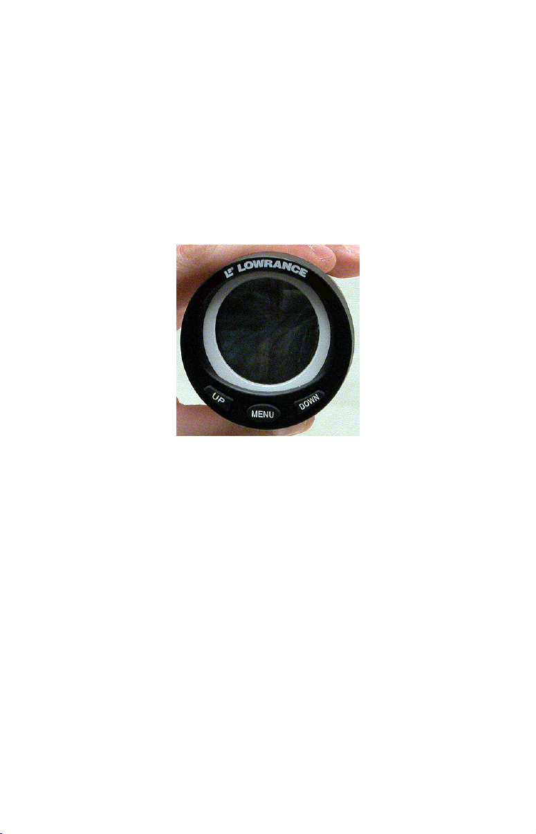
The LMS-525cDF is one of many Lowrance display units that may be
used to configure an EP-60R Fuel Flow sensor.
NOTE:
Your unit may have NMEA 2000 menu or a Networking menu,
depending on your display unit's software version. Both menus
allow you to perform the same NMEA 2000 related functions.
Bus Setup
Selecting Bus Setup from the NMEA 2000 or Networking menu will
open the Bus Configuration menu, giving you access to the EngineTank Configuration menu and the NMEA 2000 Devices list.
The list, located in the top half of the Bus Configuration menu, shows
all devices connected to the network. The Engine-Tank Configuration
menu is located in the bottom half of the Bus Configuration menu. The
network devices list is located in the top half of the Bus Configuration
menu.
33
Page 34

Bus Setup highlighted on the NMEA 2000 menu (left). Bus Setup
selected on Networking menu (right).
The Engine-Tank Configuration and Tank Select menus as well as the
Tank Size dialog box are located on the bottom half of the Bus
Configuration menu. The Set Configuration button — positioned next
to the engine-tank configuration menu — allows you to finalize a
selected configuration.
Bus Configuration menu (left). NMEA Diagnostics page (center).
Ethernet Diagnostics (right).
The NMEA Diagnostics page displays information about the
performance of the network bus, keeping you updated on bus status,
mode, errors and bus traffic. The Ethernet Diagnostics page keeps you
updated on the performance of an Ethernet connection (if applicable)
supplying information ranging from IP Address to upload and
download rates (bytes per second). To refresh either Diagnostics page,
highlight the
ENT.
PING ALL DEVICES button at the bottom of the page and press
Engine & Tank Configuration
The Engine-Tank configuration menu is located below the NMEA 2000
Devices list, but will only be accessible if a fuel-related sensor is on the
network.
34
Page 35

Setting Engine-Tank Configuration:
1. Press MENU twice, highlight NMEA 2000 or NETWORKING and press
ENTER.
2. The NMEA 2000 menu will appear with five options: Bus Setup,
Fuel Management, NMEA 2000 Alarms, Waypoint Sharing and
Backlight Synchronization. Choose
3. Select
ENGINE & TANK CONFIG and press ENTER, which will open the
BUS SETUP and press ENTER.
Engine & Tank Configuration menu with the following configuration
options: 1 Engine/1 Tank, 1 Engine/2 Tanks, 2 Engines/1 Tank, 2
Engines/2 Tanks, 3 Engines/1 Tank, 3 Engine/3 Tanks and
Unconfigured Bus.
4. Choose the configuration that matches the number of engines and
tanks on your vessel and press
5. Highlight
TANK SELECT and press ENTER, which will open the Tank
ENTER.
Select menu.
6. Select the tank you want to set up and press
Tank Size dialog box and press
ENTER.
ENTER. Highlight the
1 Engine/1Tank highlighted on Engine and Tank Configuration
menu (left). Starboard highlighted on Tank Select menu (center).
Tank Size set to 40 gallons (right).
7. Input the capacity (gallons) of the tank you chose from the Tank
Select menu and press
ENTER.
8. Repeat Steps 5-7 for each remaining tank.
9. When all tanks have been configured, press the
SET CONFIGURATION
button. The following confirmation message will appear: Are you sure
you wish to change the bus configuration? Choose
Press
EXIT to return to the main display.
YES and press ENTER,
NMEA 2000 Devices List
Devices connected to your NMEA 2000 network will be listed on the
NMEA 2000 Devices list, located at the top of the Bus Configuration
35
Page 36

menu. To configure or calibrate most devices, you will select it on the
NMEA 2000 Devices list and press
ENTER. This will open its Device
Configuration menu.
Bus Configuration menu with five items displayed on the NMEA 2000
Devices list. Engine-Tank Configuration and Tank Select menus are at
the bottom of the screen.
Device Configuration Menu
When a device is selected from the network devices list on the Bus
Configuration menu, its Device Configuration menu will appear. Device
configuration menus vary among devices. Available functions on device
configuration menus allow you to change device names, tank sizes,
fluid types and provide access to the Advanced Options menu. We will
cover configuration and calibration later in this section.
Device Information and Device Data
The Device information panel, located to the left of the Device
Configuration menu, displays information on the selected device that
includes, software version, model, address, serial number, instance and
current status.
Device Data is shown in the Device Data window at the bottom of the
device configuration menu. The information displayed in the Device
Data window will vary among devices. If, for example, you are viewing
the device configuration menu for an EP-65R Fluid Level, the device
data window will include tank size and the amount of fuel left in the
tank.
The Device Data for an EP-60R Fuel Flow includes Fuel Rate (amount
of fuel burned per hour), Fuel Used, Trip Fuel Used and Seasonal Fuel
Used.
36
Page 37

EP-60R Fuel Flow Configuration
When configuring your fuel flow, you will open its Device Configuration
menu where you can access the Location and Advanced Options menu.
You can also change your fuel flow's device name.
Device Name
You can change how your fuel flow will be displayed on your unit's
NMEA 2000 Devices list by inputting a customized device name in the
Device Name dialog box.
NOTE:
Changing the Device Name only will affect the way the EP-60R is
shown on your display unit. The customized device name will not
be seen by other devices or display units on the NMEA 2000
network.
To change Device Name:
1. Press MENU twice, select NMEA 2000 or NETWORKING and press ENTER.
2. Highlight
from the Bus Devices list and press
3. Device Name will be highlighted. Press
Name dialog box.
BUS SETUP and press ENTER. Select the desired fuel flow
ENTER.
ENTER to access the Device
4. Use the
have finished inputting the desired Device Name, press
EXIT repeatedly to return to the main display.
To reset device name to default setting:
UP and DOWN keys to change the Device Name. When you
ENTER. Press
1. Press MENU twice, select NMEA 2000 or NETWORKING and press ENTER. A
menu will appear with five options: Bus Setup, Fuel Management,
NMEA 2000 Alarms, Waypoint Sharing and Backlight
Synchronization.
2. Highlight
BUS SETUP and press ENTER, which will open the Bus
Configuration menu. A list of network devices will be at the top of the
page.
3. Select the fuel flow with the device name you want to reset and press
ENTER. The Device Configuration menu will appear with the Device
Name dialog box highlighted.
4. Press
disappears. Press
ENTER. Depress the left arrow key until the device name
ENTER, then press EXIT to return to the NMEA 2000
menu.
37
Page 38

5. Highlight the device and press
ENTER. The Device Configuration
menu will open. The device name will be reset to its default setting.
Press
EXIT repeatedly to return to the main display.
Location
The Location menu allows you to select a configuration name that
matches the location of the engine connected to your fuel flow sensor.
To change fuel flow location:
1. Press MENU twice, select NMEA 2000 or NETWORKING and press ENTER. A
menu will appear with five options: Bus Setup, Fuel Management,
NMEA 2000 Alarms, Waypoint Sharing and Backlight
Synchronization.
2. Highlight
BUS SETUP and press ENTER, which will open the Bus
Configuration menu. A list of network devices will be at the top of the
page.
3. Select the fuel flow you want to configure and press
ENTER. The
Device Configuration menu will appear.
4. Select
LOCATION and press ENTER, which will open the Location menu.
NOTE:
If you want to unconfigure your fuel flow, select
UNKNOWN from the
Location menu.
5. Highlight the desired location and press
ENTER. The following
message will appear: Are you sure you wish to change this device's
configuration?
6. Select
YES and press ENTER. Press EXIT repeatedly to get back to the
main display.
Unconfiguring an EP-60R Fuel Flow
You can unconfigure a fuel flow by manually resetting its Location to
default settings (Unknown) via the Location menu or you can use the
Restore Defaults command.
To reset the fuel flow's device name, refer to the previous segment
covering Device Name. The Device Name also may be reset by using
the Restore Defaults command.
NOTE:
If you execute the Restore Defaults command, you will have to reenter your engine-tank configuration settings. The Restore
Defaults command is covered at the end of this section.
38
Page 39

Fuel Management highlighted on Networking menu (left). Fuel
Management menu (right).
Fuel Management Menu
The Fuel Management menu gives you access to the following options:
Tank Location, Fuel Added, Add Fuel, Fill Tank, Engine Select, Reset
Calibration, Reset Trip and Reset Seasonal. The menu is divided into two
parts: Tank Operations and Engine Operations. You will calibrate your
fuel flow from Tank Operations section of the Fuel Management menu.
Engine Operations are located in the lower half of the menu.
Tank Operations
The top half of the Fuel Management menu covers Tank Operations,
which include Tank Location, Fuel Added, Add Fuel and Fill Tank.
Adding Fuel to Tank
Tank Location, Fuel Added and Add Fuel commands work together to
keep NMEA 2000 fuel data consistent with the actual amount of fuel
added to the fuel tank(s).
1. Press
2. A menu will appear with five options: Bus Setup, Fuel Management,
NMEA 2000 Alarms, Waypoint Sharing and Backlight
Synchronization. Select
3. Highlight
will appear.
4. Select the tank you added fuel to and press
5. Follow the steps below that apply to your tank.
MENU twice, select NMEA 2000 or NETWORKING and press ENTER.
FUEL MANAGEMENT and press ENTER.
TANK LOCATION and press ENTER. The Tank Location menu
ENTER.
39
Page 40

If you filled up the tank:
A. Press the FILL TANK button and press ENTER. The following message
will appear: Are you sure you wish to Fill Tank? Press
ENTER. Another
message will appear: Do you wish to re-calibrate the device? Highlight
NO and press ENTER.
If you did not fill up the tank:
B. Highlight FUEL ADDED and press ENTER to access the FUEL ADDED dialog
box. Use ↑ ↓ , ← → to input the amount of fuel added to the tank and
ENTER. Select the ADD FUEL button and press ENTER. The following
press
message will appear: Are you sure you wish to Add Fuel? Highlight
and press
6. Press
ENTER.
EXIT repeatedly to get back to the main display.
YES
EP-60R Fuel Flow Calibration
The default calibration for the EP-60R Fuel Flow is adequate in most
cases, but if Fuel Used readings are off by more than 3 percent,
calibration is recommended.
Fuel Flow Accuracy
To check fuel flow accuracy you must overlay Fuel Used data on your
display to be able to check the accuracy of fuel information coming from
the fuel flow.
To overlay Fuel Used data on your screen:
1. Press MENU, select OVERLAY DATA and press ENTER.
2. If you currently have any overlay data on your screen, it will be
listed here. Select
3. Highlight
the NMEA 2000 Devices list.
4. Select
EP-60R FUEL FLOW and press ENTER and a list of data options
will appear.
5. Highlight
(ENTER TO ADD) and press ENTER.
NMEA 2000 or NETWORKING and press ENTER, which will open
FUEL USED and press ENTER.
6. Press
EXIT twice to return to the page display, where Fuel Used data
will be displayed on the screen.
To check fuel flow accuracy:
1. After selecting Fuel Used as overlay data, fill up your tank and press
MENU twice. Select NMEA 2000 or NETWORKING and press ENTER.
2. Highlight
press
ENTER.
3. Select the tank location and press
FUEL MANAGEMENT and press ENTER. Select TANK LOCATION and
ENTER.
40
Page 41

4. Highlight
FILL TANK and press ENTER. The following confirmation
message will appear: Are you sure you wish to Fill Tank?
NOTE:
You must use the unit’s Fill Tank command when filling your fuel
tank to keep the fuel flow updated with correct information on the
amount of fuel in the tank.
5. Select
YES and press ENTER. The following confirmation message will
appear: Do you wish to re-calibrate the device?
6. Highlight
NO and press ENTER.
7. Take your vessel out on the water and burn at least five gallons of
fuel. Be sure you run only ONE engine — the engine connected
to your fuel flow.
8. Fill up your tank again, noting how much fuel you added to the tank.
Compare that number to the Fuel Used figure displayed on your
display unit's screen.
If the amount of fuel you added to the tank and the fuel used figure are
off by more than 3 percent, we recommend the fuel flow be calibrated.
To calibrate a fuel flow:
9. Fill up your tank. Press MENU twice, select NMEA 2000 or NETWORKING
and press ENTER.
10. Highlight
and press
FUEL MANAGEMENT and press ENTER. Highlight TANK LOCATION
ENTER.
11. Select the desired tank location and press ENTER.
12. Highlight
appear: Are you sure you wish to Fill Tank? Select
ENTER.
FILL TANK and press ENTER. The following message will
YES and press
13. The following message will appear: Do you wish to re-calibrate the
device? Select
YES and press ENTER.
14. Repeat these steps for each EP-60R Fuel Flow you want to
calibrate.
Engine Operations
The lower half of the Fuel Management menu covers Engine
Operations, which include: Engine Select, Reset Calibration, Reset Trip
and Reset Seasonal.
Engine Select
Engine Select allows you to choose the desired engine when resetting
calibration, resetting trip fuel and resetting seasonal fuel.
41
Page 42

To Reset Calibration:
Choosing the Reset Calibration command will switch fuel flow
calibration settings back to factory defaults.
1. Press
MENU twice, select NMEA 2000 or NETWORKING and press ENTER.
2. Highlight FUEL MANAGEMENT and press ENTER. 3. Highlight to ENGINE
SELECT and press ENTER. Select the desired engine and press ENTER.
4. Highlight
RESET CALIBRATION and press ENTER. The following
confirmation message will appear: Are you sure you wish to Reset
Calibration? Select
YES and press ENTER. Calibration settings for the
selected fuel have been returned to factory defaults.
To Reset Trip:
The Reset Trip function allows you to reset to zero the running total of
fuel used on a particular trip.
1. Press
2. Highlight
MENU twice, select NMEA 2000 or NETWORKING and press ENTER.
FUEL MANAGEMENT and press ENTER. The Fuel Management
menu will appear.
3. To reset trip fuel used for a particular engine, highlight
and press
ENTER.
4. Highlight
ENTER. Select the desired engine or All Engines and press
RESET TRIP and press ENTER. The following confirmation
ENGINE SELECT
message will appear: Are you sure you wish to Reset Trip?
5. Highlight
YES and press ENTER. The Trip Fuel Used figure has been
reset to zero.
To Reset Seasonal:
Your unit can track fuel usage not only for trips, but also for entire
seasons. The reset seasonal command allows you to reset to zero the
running total of fuel used during a season.
1. Press
2. Highlight
MENU twice, select NMEA 2000 or NETWORKING and press ENTER.
FUEL MANAGEMENT and press ENTER.
3. To reset seasonal trip fuel used for a particular engine, highlight
ENGINE SELECT and press ENTER. Select the desired engine or All Engines
and press
4. Highlight
ENTER.
RESET SEASONAL and press ENTER. The following
confirmation message will appear: Are you sure you wish to Reset
Seasonal?
5. Highlight
YES and press ENTER. The Seasonal Fuel Used figure has
been reset to zero.
42
Page 43

Displaying data from fuel flow
The Overlay Data function will be used to show EP-60R Fuel Flow data
on your unit's main display.
To add overlay data from the EP-60R:
1. Press MENU, highlight OVERLAY DATA and press ENTER.
2. Select
3. Highlight
(PRESS ENT TO ADD…) and press ENTER.
NMEA 2000 and press ENTER. A list of devices on the
network will appear.
4. Select the desired fuel flow and press
ENTER. Fuel Rate, Fuel Used,
Trip Fuel Used and Seasonal Fuel Used categories will appear.
5. Highlight the data you want to display and press
ENTER, which will
place a checkmark in its enabled box. It now will be shown as overlay
data on your unit's main display.
6. Repeat step 5 to display another data category, or press
EXIT
repeatedly to return to the main display.
NMEA 2000 Alarms
The NMEA 2000 Alarms menu allows you to set Full and Empty fuel
alarms for a number of NMEA 2000 devices. The alarms may be set to
a percentage (0-100%) of tank capacity.
To turn on/off NMEA 2000 Alarm:
1. Press MENU twice, select NMEA 2000 or NETWORKING and press ENTER.
2. Highlight
3. Highlight
flow and press
4. Highlight the
Empty Alarm) and press
is on an "X" will be placed in the Enabled Box.
5. To set the alarm percentage, highlight
6. Use the arrow keys to input the desired percentage and press
Repeat Steps 3-4 to set the other alarm.
7. Highlight
settings. Press
NOTE:
To turn off (uncheck) an alarm, select its
ENTER. Highlight the SET CONFIGURATION button and press ENTER.
NMEA 2000 ALARMS and press ENTER.
FLUID LEVEL DEVICE and press ENTER. Select the desired fuel
ENTER.
ENABLED box next to the desired alarm (Full Alarm or
ENTER to turn on the alarm. When the alarm
PERCENT and press ENT.
ENTER.
SET CONFIGURATION and press ENTER to finalize alarm
EXIT repeatedly to get back to the main display.
ENABLED BOX and press
43
Page 44

Alarm Status Tab
The Alarm Status tab is the second tab at the top of the NMEA 2000
Alarms page. When an alarm has been set for a device, the alarm and
its current status will be shown on the Alarm Status window.
To view Alarm Status:
1. Press MENU twice, select NMEA 2000 or NETWORKING and press ENTER.
2. Select
NMEA 2000 ALARMS and press ENTER.
3. Highlight the Alarm Status tab.
4. Press
EXIT repeatedly to return to the main display.
Restore Defaults
The Restore Defaults command allows you to reset EP-60R Fuel Flow
settings to factory defaults.
NOTE:
After using the Restore Defaults command, you will have to reenter your engine-tank configuration. It, however, will not affect
the configuration or calibration of other devices on the network.
To use the Restore Defaults command:
1. Press MENU twice, select NMEA 2000 or NETWORKING and press ENTER.
A menu will appear with five options: Bus Setup, Fuel Management,
NMEA 2000 Alarms, Waypoint Sharing and Backlight
Synchronization.
2. Highlight
BUS SETUP and press ENTER, which will open the Bus
Configuration menu. A list of network devices will be at the top of the
page.
3. Select the desired fuel flow and press
ENTER. The Device
Configuration menu will appear.
4. Highlight
5. Select
ADVANCED OPTIONS and press ENTER.
RESTORE DEFAULTS and press ENTER. The following message will
appear: Are you sure you wish to change this device's configuration?
6. Highlight
YES and press ENTER. Press EXIT repeatedly to return to
the main display.
44
Page 45

Notes
45
Page 46

Notes
46
Page 47

LOWRANCE ELECTRONICS
FULL ONE-YEAR WARRANTY
"We," "our," or "us" refers to LOWRANCE ELECTRONICS, INC., the manufacturer of
this product. "You" or "your" refers to the first person who purchases this product as a
consumer item for personal, family or household use.
We warrant this product against defects or malfunctions in materials and workmanship,
and against failure to conform to this product's written specifications, all for one (1) year
from the date of original purchase by you. WE MAKE NO OTHER EXPRESS
WARRANTY OR REPRESENTATION OF ANY KIND WHATSOEVER CONCERNING
THIS PRODUCT. Your remedies under this warranty will be available so long as you can
show in a reasonable manner that any defect or malfunction in materials or
workmanship, or any non-conformity with the product's written specifications, occurred
within one year from the date of your original purchase, which must be substantiated by
a dated sales receipt or sales slip. Any such defect, malfunction, or non-conformity which
occurs within one year from your original purchase date will either be repaired without
charge or be replaced with a new product identical or reasonably equivalent to this
product, at our option, within a reasonable time after our receipt of the product. If such
defect, malfunction, or non-conformity remains after a reasonable number of attempts to
repair by us, you may elect to obtain without charge a replacement of the product or a
refund for the product. THIS REPAIR, OR REPLACEMENT OR REFUND (AS JUST
DESCRIBED) IS THE EXCLUSIVE REMEDY AVAILABLE TO YOU AGAINST US FOR
ANY DEFECT, MALFUNCTION, OR NON-CONFORMITY CONCERNING THE
PRODUCT OR FOR ANY LOSS OR DAMAGE RESULTING FROM ANY OTHER
CAUSE WHATSOEVER. WE WILL NOT UNDER ANY CIRCUMSTANCES BE LIABLE
TO ANYONE FOR ANY SPECIAL, CONSEQUENTIAL, INCIDENTAL, OR OTHER
INDIRECT DAMAGE OF ANY KIND.
Some states do not allow the exclusion or limitation of incidental or consequential
damages, so the above limitations or exclusions may not apply to you.
This warranty does NOT apply in the following circumstances: (1) when the product has
been serviced or repaired by anyone other than us; (2) when the product has been
connected, installed, combined, altered, adjusted, or handled in a manner other than
according to the instructions furnished with the product; (3) when any serial number has
been effaced, altered, or removed; or (4) when any defect, problem, loss, or damage has
resulted from any accident, misuse, negligence, or carelessness, or from any failure to
provide reasonable and necessary maintenance in accordance with the instructions of the
owner's manual for the product.
We reserve the right to make changes or improvements in our products from time to time
without incurring the obligation to install such improvements or changes on equipment or
items previously manufactured.
This warranty gives you specific legal rights and you may also have other rights which
may vary from state to state.
REMINDER: You must retain the sales slip or sales receipt proving the date of your
original purchase in case warranty service is ever required.
LOWRANCE ELECTRONICS
12000 E. SKELLY DRIVE, TULSA, OK 74128
(800) 324-1356
47
Page 48

How to Obtain Service…
…in the USA:
Contact the Factory Customer Service Department. Call toll-free:
For Lowrance: 800-324-1356. For Eagle: 800-324-1354
8 a.m. to 5 p.m. Central Standard Time, M-F
Lowrance Electronics and Eagle Electronics may find it necessary to change or end
their shipping policies, regulations and special offers at any time. They reserve the
right to do so without notice.
…in Canada:
Contact the Factory Customer Service Department. Call toll-free:
800-661-3983
905-629-1614 (not toll-free)
8 a.m. to 5 p.m. Eastern Standard Time, M-F
…outside Canada and the USA:
Contact the dealer in the country where you purchased your unit. To locate a
dealer near you, see the instructions in paragraph number 1 below.
Accessory Ordering Information
LEI Extras™, Inc. is the accessory source for sonar and GPS products
manufactured by Lowrance Electronics and Eagle Electronics. To order
Lowrance or Eagle accessories, please contact:
1) Your local marine dealer or consumer electronics store. To locate a Lowrance
dealer, visit the web site, www.lowrance.com, and look for the Dealer Locator.
To locate an Eagle dealer, visit the web site, www.eaglesonar.com, and look for
the Dealer Locator. Or, consult your telephone directory for listings.
2) U.S. customers: LEI Extras Inc., PO Box 129, Catoosa, OK 74015-0129
Call toll free in the U.S., 800-324-0045, 8 a.m. to 5 p.m. Central
Standard Time, M-F, or visit our web site www.lei-extras.com.
3) Canadian customers: Lowrance/Eagle Canada, 919 Matheson Blvd. E.
Mississauga, Ontario L4W2R7 or fax 905-629-3118.
Call toll free in Canada, 800-661-3983, or dial 905 629-1614 (not toll free), 8
a.m. to 5 p.m. Eastern Standard Time, M-F.
For Lowrance® and Eagle® Products
Pub. 988-0154-432 © Copyright 2007
All Rights Reserved
Printed in USA 091407 Lowrance Electronics, Inc.
48
 Loading...