

Page 1
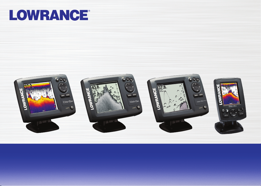
Elite 5X, Mark 5X, Mark 5X Pro & Elite 4X
Installation & Operation
manual
Operation manual
Page 2

Copyright © 2011 Navico
All rights reserved.
Lowrance® and Navico® are registered trademarks of Navico.
Navico may nd it necessary to change or end our policies, regulations and special oers at any time. We reserve
the right to do so without notice. All features and specications subject to change without notice.
Visit our website:
www.lowrance.com
Page 3

Table of Contents
Introduction ...................................... 2
Basic Operation ............................... 3
Setup wizard ............................................ 3
Working with menus ................................4
Fishing Mode ........................................... 5
Cursor ...................................................... 6
Advanced Mode ......................................6
Standby mode .........................................7
Restore defaults ......................................7
Pages ................................................ 8
Sonar Page..............................................8
Split Frequency........................................8
Split Zoom ...............................................9
Overlay Data............................................9
Using your Sonar ............................11
Trackback .............................................. 11
Sensitivity ..............................................12
Colorline/Grayscale ............................... 12
Depth Range .........................................13
Frequency .............................................14
Ping Speed (Advanced Mode only) ....... 14
Sonar Options........................................14
Settings .......................................... 17
System...................................................17
Sonar .................................................... 19
Surface Clutter.......................................19
Installation .............................................20
Alarms ..................................................21
Index ............................................... 22
Specications ................................ 23
1
Page 4
Introduction
Introduction
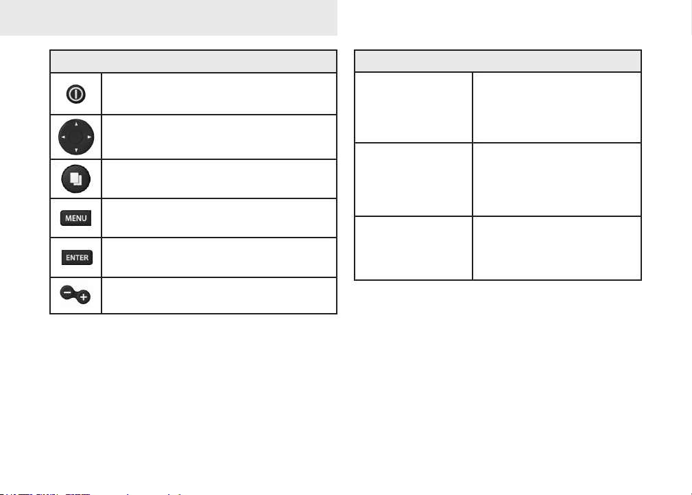
Unit Controls
LIGHT/POWER: controls backlight
level and turns unit on/off
KEYPAD: controls cursor & selects
items on menus
PAGES: allows you to select a page to
view
MENU: opens settings, context and
page menus
ENTER: nalizes menu selections;
save waypoint at cursor position
ZOOM Keys: used to zoom in/zoom
out
Getting Started
Turn unit on/off
Adjusting
the backlight
Muting Audio
To turn on/off the unit,
press and hold the LIGHT/
POWER key for three
seconds.
This unit has
levels. Press the LIGHT/
POWER key to switch
backlight levels.
Select Mute Audio from
the System menu and
press ENTER.
10 backlight
2
Page 5
Basic Operation
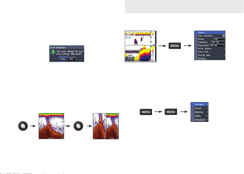
Setup wizard
The Setup wizard will appear when the unit is
turned on for the rst time. To choose your own
settings, do not run the setup wizard.
To restart the Setup wizard, restore defaults.
Pages
This unit has three pages: Sonar, Split Frequency
and Split Zoom.
Accessing Sonar menu
Sonar Page
Sonar menu
Accessing the Settings menu
Settings menu
3
Page 6
Basic Operation
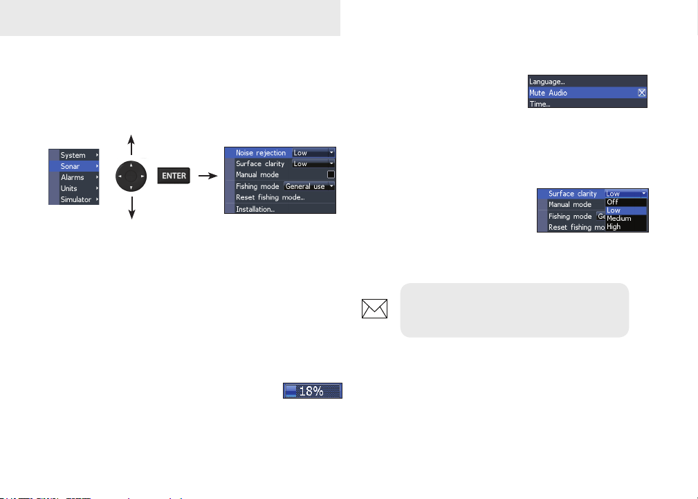
Accessing menu items
The keypad and ENTER key are used to select
menu items and open submenus. Use the keypad
to highlight the desired item and press ENTER.
Working with menus
There are several menu types used to make
adjustments to options and settings, including
scrollbars, on/o features and dropdown menus.
Scrollbars
Select the scrollbar and press the keypad left (decrease) or right (increase).
On/Off features
Select an on/o menu item
and press ENTER to turn it
on/o.
Dropdown menus
After accessing the dropdown
menu, press the keypad up/
down to select the desired
item and press ENTER.
NOTE: Press the MENU key to Exit
menus.
4
Page 7
Basic Operation
Dialogs
Dialogs are used for user input or for presenting information to the user.
Depending on the type of information or entry, dierent methods are used to conrm, cancel or
close the dialog.
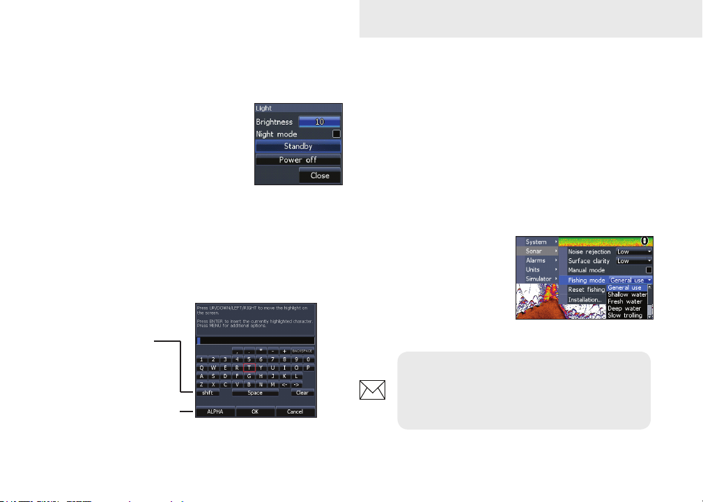
Entering text
Some functions, like naming a waypoint, route or
trail, will require you to input text.
Switches letters
to uppercase/
lowercase
Switches
keyboard between
Alpha and
QWERTY layout
To input text:
1. Use the keypad to select the desired
character and press ENTER.
2. Repeat Step 1 for each character.
3. When entry is completed, highlight OK
and press ENTER.
Fishing Mode
Fishing modes enhance
the performance of your
unit by providing preset
packages of sonar settings geared to specic
shing conditions.
NOTE: Use Fresh Water mode when
shing in less than 100 feet of water;
otherwise your unit may not track bottom
properly.
5
Page 8
Basic Operation
Fishing Mode Options
General
Use
Shallow
Water
Fresh
Water
Deep
Water
Slow
Trolling
Fast
Trolling
Clear
Water
Brackish
Water
Bottom brown/white background; 50% ping
speed
Bottom brown/white background
Bottom brown/white background; 50% ping
speed
Deep Blue; 50% ping speed; 50kHz is primary
transducer frequency
Bottom brown/white background; 50% ping
speed
Bottom brown/white background; slightly lower
chart speed
Bottom brown/white background; 50% ping
speed
Bottom brown/blue background; higher ASP;
slightly lower chart speed
Cursor
The keypad moves the cursor on the display and
allows you to review Sonar history. Press MENU
and select Exit cursor mode to clear the cursor.
Advanced Mode
Enables advanced features
and settings.
The following features are enabled when Advanced
mode is turned on:
• Colorline (manual control)
• Surface Clarity (manual control)
• Ping Rate (manual control)
• Units (Enables distance, speed, depth
and temperature options)
6
Page 9

Standby mode
Lowers power consumption by turning o sonar
and the display.
Press the PWR/LIGHT key to access the Backlight menu. Select
Standby and press ENTER.
Press any key to resume normal operation.
NOTE: Leaving your unit in Standby mode
when your boat is not is use will run down
your battery.
Restore defaults
Resets unit options and settings to defaults.
Basic Operation
7
Page 10

Pages
Overlay Data
Location and depth
Surface Clutter
Sonar Page
Fish arches
Frequency
Colorline
Range Scale
Amplitude Scope
Cursor
Depth
Displays the water column moving from right to
left on your unit’s screen. On the right side of the
screen, the Amplitude Scope bar previews echoes
about to appear on the display.
Split Frequency page
Split Frequency
Displays both transducer frequencies at the same
time. 83 kHz has a wider cone angle for greater water coverage, while 200 kHz has the highest sensitivity and best target discrimination in shallow water. (Does not apply to the Mark 5X.)
8
Page 11

Split Zoom
Pages
Overlay Data
Displays selected overlay data on the sonar page.
Overlay data
Show
Enables/disables the display of overlay data, allowing you to remove overlay data from the screen
without deleting the selected overlay data conguration.
Split Zoom
Allows you to zoom in for a closer look without losing your view of the water column.
Congure
Used to select overlay data to be displayed on the
screen.
9
Page 12

Pages
To select overlay data:
1. From the sonar page, press MENU.
2. Select Overlay data and press ENTER.
3. Select Congure and press ENTER.
4. Press Menu and select Add. Press
ENTER.
5. Select the desired data from the Con-
gure Items to show screen. Press ENTER.
6. Press MENU and select Return to
overlays.
7. Press MENU, select Done Conguring
and press ENTER.
Customizing Overlay Data
Access the Overlay Data conguration menu to
make adjustments to the size and/or location of
overlay data on the display.
Press Menu from the Congure Item Locations and
Sizes screen to access the menu.
10
Page 13

Sonar
Using your Sonar
Trackback
You can review your recent sonar history by moving the cursor to the left until the screen starts to
move in reverse.
Cursor depth
Move the blue sonar history bar all the way to the
right to resume normal sonar scrolling.
Press MENU and select Exit cursor mode to remove the cursor from the screen.
Sonar Menu
The sonar menu has options
and settings that aect the
appearance of the display.
Blue sonar history bar
11
Page 14

Sonar
Press MENU from any sonar page to access the Sonar menu.
Sonar Menu
(Advanced Mode)
Adjust (Advanced Mode only)
Used to make adjustments to
Sensitivity, Colorline and Grayline.
Sensitivity set
to 65 percent.
Sensitivity set
to 85 percent.
Sensitivity
Controls the level of detail shown on the display.
Too much detail will clutter the screen. If Sensitivity
is set too low, desired echoes may not be displayed.
Colorline/Grayscale
Separates strong sonar echoes from weak sonar
echoes. That makes it easier for you to distinguish
sh or structure from the bottom. A hard return
will be shown as a wide, bright yellow area,
whereas a soft return will be a narrow reddishblue area.
12
Page 15

Sonar
Mark series units have a monochrome display,
so wide bands of gray indicate a hard sonar
return, while softer returns are shown as dark,
narrow areas.
Auto Sensitivity
Keeps sensitivity at a level that works well under
most conditions, reducing the needs for adjustments. Auto Sensitivity is turned on by default.
NOTE: You can make minor (+/-4%)
changes to sensitivity with Auto Sensitivity
turned on. You will have to turn it o to
make signicant adjustments.
Depth Range
Selects the deepest range shown on
the display. Range settings display the
section of the water column from the
water surface to the selected depth
range. If you select too shallow a depth range the
unit will not be able to lock onto the bottom.
Custom Range — Upper and Lower Limits
(Advanced Mode only)
Used to select the upper limit and lower limit of
a section of the water column. That allows you to
view a section of the water column that does not
include the water surface. Upper and lower limits
must be at least 6.5 ft (2m) apart.
Custom range menu
NOTE: When using a custom range,
you may not receive any digital depth
readings, or you may receive incorrect
depth information.
13
Page 16

Sonar
Frequency
Controls the transducer frequency used by the
unit. This unit supports two frequencies: 200kHz
and 83kHz.
200 kHz has the highest sensitivity and best target discrimination in shallow water. 83 kHz oers
a wider cone angle for more water coverage. The
Mark 5X only supports the 200kHz transducer frequency.
Ping Speed (Advanced Mode only)
Controls the rate the transducer uses to send sonar
waves into the water. Ping speed adjustments can
help reduce interference from other transducers.
Frequency menu
When using shing modes, ping speed settings are
optimized for the selected shing conditions, so in
most cases, adjustments are not necessary.
Sonar Options
Accesses sonar display settings and conguration
options.
Split Zoom and Split Flasher
Switches the sonar display from full screen sonar to
a split screen view.
Split FlasherSplit Zoom
14
Page 17

Sonar
Color
Allow you to change the look of the display using
palettes with varying degrees of color/brightness.
Nightview
Iceview
Monochrome units support Grayscale, Reverse
Grayscale and Bottom Black.
Amplitude Scope
Displays the amplitude of realtime echoes before they appear
Amplitude
scope
on the display.
Fish ID
Displays sh echoes as sh symbols instead of sh arches. Fish ID
is not the most accurate method
of sh detection since structure
and suspended debris may be
shown as a sh symbol on the
display.
Ice Mode
Turns on a package of sonar settings optimized for
ice shing and also overlays battery meter data on
the screen.
Stop Sonar
Pauses the sonar chart, allowing you to get a closer
look at suspended targets.
Stop Sonar also can be used to prevent/stop interference between two units running on the same
boat at the same time.
15
Page 18

Sonar
Overlay Data
Allows you to select data (water temperature, depth, etc)
to be displayed on top of the
Sonar screen.
Overlay data setup is covered
in the Pages section.
Settings
Accesses the Sonar settings menu.
Overlay data
16
Page 19

Settings
Settings Menu
Accesses to installation and conguration settings
for your unit.
Settings
menu
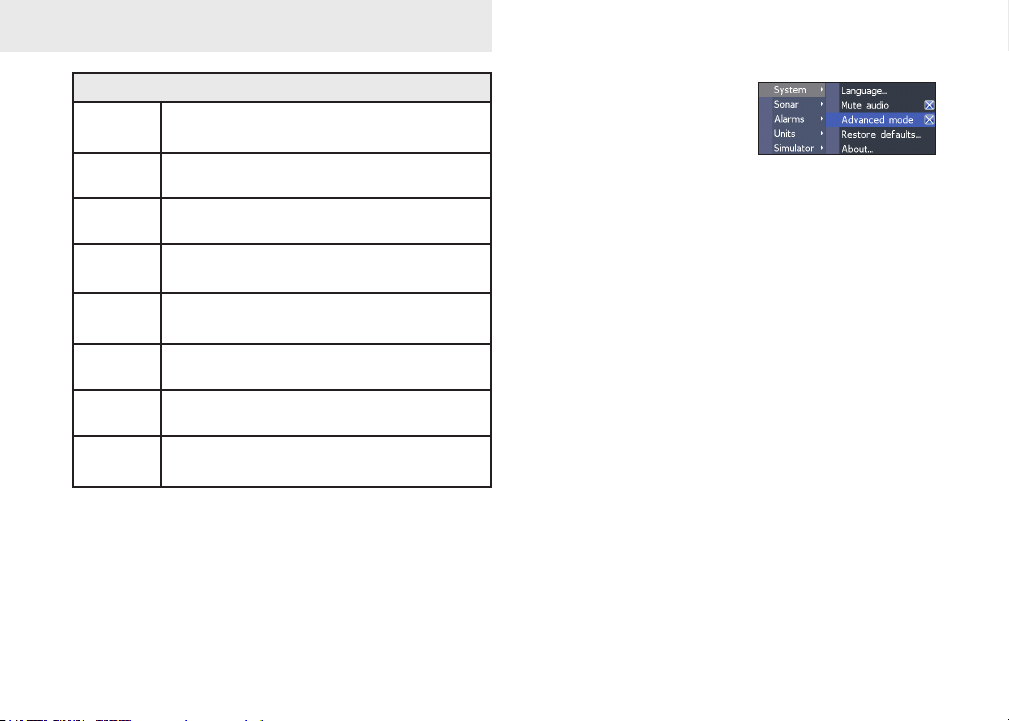
System
Adjusts unit settings like language, mute audio
and advanced mode.
Enables
advanced
features and
settings
System menu
Displays
software
information
17
Page 20

Settings
Set Language
Selects the language used on menus and text
boxes.
Mute Audio
Turns on/o unit audio, like key beeps, alarm
sounds, etc.
Advanced Mode
Enables features and settings only available with
unit in Advanced Mode.
Restore Defaults
Switches the unit back to default
settings.
About
Displays software information about this unit. Before attempting a software update, you can check
the version of software your unit is using by accessing the About screen.
Lowrance periodically updates unit software to
add features and improve functionality. To see the
latest available software version go to www.lowrance.com.
18
Page 21

Settings
Sonar
Used to make adjustments to Sonar options and
display settings like Noise Rejection, Surface and
Fishing Mode.
Sonar Settings Menu
Noise Rejection
Uses advanced signal processing to monitor the effects noise (boat pumps, water conditions, engine
ignition systems, etc.) has on your display, and then
lters out the undesired signals.
Surface Clarity
(Advanced Mode only)
Surface Clarity reduces
surface clutter by decreasing
the sensitivity of the receiver
near the surface.
Manual Mode
Restricts digital depth capability, so the unit will
only send sonar signals to the selected depth
range. That allows the display scroll smoothly if the
bottom depth is out of transducer range.
Surface Clutter
19
Page 22

Settings
WARNING: Manual mode should only
be used by advanced sonar users.
When the unit is in manual mode, you may not receive any depth readings, or you may recieve incorrect depth information.
Fishing Mode
Enhances the performance of your unit by
providing preset packages of
sonar settings geared to specic
shing conditions. For more
information about shing modes,
refer to the Basic Operation
section.
Reset Fishing Mode
Resets selected shing mode to default settings.
That is useful when you want to clear settings adjustments made while using a shing mode.
Installation
Provides access to Keel Oset and Temp Calibration
settings.
Installation menu
Keel Offset
All transducers measure water depth from the
transducer to the bottom. As a result, water depth
readings do not account for the distance from the
transducer to the keel or from the transducer to the
water surface.
Transducer
Keel Offset (-3.5 feet)
Keel
20
Page 23

Settings
Before setting keel oset, measure the distance
from the transducer to the lowest part of the keel.
If, for example, the keel is 3.5 feet below the transducer, it will be input as –3.5 feet.
Temperature calibration
Calibrates data from the transducer temperature
sensor with data from a known temperature source
to ensure the accuracy of temperature information.
Reset water distance
Reset Water Distance to zero.
Alarms
Enables alarms and selects alarm thresholds. Arrival, O Course and Anchor alarms are only available
in Advanced mode.
Alarms
Shallow
Fish
sounds alarm when vessel enters water
shallower than the selected shallow threshold
sounds alarm when a sh symbol (Fish ID)
appears on the sonar screen
Units
Allows you to select the unit of measure used by
the unit. Unit options vary depending on whether
the unit is in basic or advanced mode.
Basic Mode
Advanced Mode
Simulator
Simulates on-the-water sonar activity.
21
Page 24

Index
A
About 18
Advanced Mode 6
Alarms 21
Fish 21
Shallow 21
Amplitude Scope 15
Auto Sensitivity 13
C
Color 15
Colorline 12
Cursor 6
Custom Range 13
D
Depth Range 13
Dialogs 5
Dropdown menus 4
F
Fish alarm 21
Fish ID 15
Fishing Mode 5
Frequency 13
I
Ice Mode 15
Installation menu 20
K
Keel Oset 20
L
Language 18
M
Manual Mode 19
Mute Audio 18
N
Noise Rejection 19
O
On/O features 4
Overlay Data , 9
Congure 9
Customizing 10
Show 9
P
Ping Speed 14
R
Range 13
Reset Fishing Mode 20
Reset water distance 21
Restore defaults 7
S
Scrollbars 4
Sensitivity 12
Settings Menu 17
Setup wizard 3
Shallow alarm 21
Simulator 21
Software update 18
Sonar
22
Adjust 12
Sonar Installation 20
Sonar Menu 11
Sonar Options 14
Sonar Page 8
Sonar settings 19
Split Flasher 14
Split Frequency 8
Split Zoom 9, 14
Standby mode 7
Stop Sonar 15
Surface Clarity 19
System settings 17
T
Temperature calibration
21
Text entry 5
Trackback 11
U
Units 21
Upper and Lower Limits
13
Page 25

Specications
Elite 5x, Mark 5x & Mark 5x Pro
General
Case size
Display
Backlight
Transmit
power
Power
requirement
Voltage input 10 to 17V
Current drain Typical: .25A
Fuse type 3 amp automotive (not supplied)
5.4” H (134mm) x 6.8” W (174mm); 6” H
(152mm) with bracket
Mark: (5” diagonal) High-contrast lm
Supertwist LCD; 16-level grayscale denition;
480x480 monochrome
Elite: (5” diagonal) Enhanced Solar MAX™
480x480 color
Mark: White LED
Elite: Cold cathode uorewscent lamp (10
levels)
Power
Mark 5x: 1600W PTP 200W RMS
Mark 5x Pro: 2400W PTP; 300 RMS
Elite 5x: 4000 PTP; 500W RMS
12V
Sonar
Max depth
Transducer
frequency
Max speed 70mph
Transducer Skimmer with built in temp sensor
Transducer
cable
Mark 5x: 800ft (244m)
Mark 5x Pro/Elite 5x: 1000ft (305m)
Mark 5x: 200kHz
Mark 5x Pro/Elite 5x: 83/200kHz
20 feet (6m)
Page 26

Specications
Elite 4x
General
Case size
Display
Backlight
Transmit
power
Power
requirement
Voltage input 10 to 17V
Current drain at 13.5V (200mA)
Fuse type 3 amp automotive (not supplied)
5.6” H (144mm) x 3.7” W (94.3mm); 6.4” H (164mm)
with bracket
(3.5” diagonal) 320x240 (256 color) TFT LCD
White LED (10 levels)
Power
2100W PTP; 262W RMS
12V
Sonar
Max depth 1000ft (305m)
Transducer
frequency
Max speed 70mph
Transducer Skimmer with built in temp sensor
Transducer
cable
83/200kHz
20 feet (6m)
Page 27

How to Obtain Service… …in the USA:
Contact the Factory Customer Service Department. Call toll-free:
800-324-1356
8 a.m. to 5 p.m. Central Standard Time, M-F
Navico may nd it necessary to change or end shipping policies, regulations and special oers at any time. They reserve the right to
do so without notice.
…in Canada:
Contact the Factory Customer Service Department. Call toll-free:
800-661-3983
905-629-1614 (not toll-free)
8 a.m. to 5 p.m. Eastern Standard Time, M-F
…outside Canada and the USA:
Contact the dealer in the country where you purchased your unit. To locate a dealer near you, see the instructions in
paragraph number 1 below.
Accessory Ordering Information
LEI Extras is the accessory source for sonar and GPS products manufactured by Lowrance Electronics. To order
Lowrance accessories, please contact:
1) Your local marine dealer or consumer electronics store. To locate a Lowrance dealer, visit the web site, www.lowrance.com, and look for the Dealer Locator; or, consult your telephone directory for listings.
2) U.S. customers visit our web site www.lei-extras.com.
3) Canadian customers: Lowrance Canada, 919 Matheson Blvd. E. Mississauga, Ontario L4W2R7 or fax 905-629-3118.
Call toll free in Canada, 800-661-3983, or dial 905 629-1614 (not toll free), 8 a.m. to 5 p.m. Eastern Standard Time, M-F.
Page 28

www.lowrance.com
*988-10157-001*
Visit our website:
© Copyright 2011
All Rights Reserved
Navico Holding AS
 Loading...