

Page 1
Handheld Mapping GPS Receiver
AirMap 500
Operation Instructions
Page 2

AirMap
Jeppesen
Navionics
DURACELL
RAYOVAC
eXitSource Database, copyright 2001-2003 Zenrin Co.
Ltd. Exit Authority and eXitSource are trademarks of
Zenrin Co. Ltd.
Copyright © 2003 Lowrance Electronics, Inc.
All rights reserved.
, Lowrance Avionics and Lowrance are all registered
trademarks of Lowrance Electronics, Inc.
is a registered trademark of Jeppesen Sanderson, Inc.
is a registered trademark of Navionics, Inc.
is a registered trademark of Duracell, Inc.
is a registered trademark of Rayovac Corporation.
Points of Interest Data in this unit are by infoUSA,
copyright 2001-2003, All Rights Reserved. infoUSA is a
trademark of infoUSA, Inc.
Lowrance Electronics may find it necessary to change or end our
policies, regulations and special offers at any time. We reserve the right
to do so without notice. All features and specifications subject to change
without notice. All screens in this manual are simulated.
For free owner's manuals and other information,
visit our web site:
www.lowrance.com
Lowrance Electronics Inc.
12000 E. Skelly Dr.
Tulsa, OK USA 74128-2486
Printed in USA.
Page 3

Table of Contents
Sec. 1: Read Me First! ............................................................... 1
Capabilities and Specifications .................................................... 3
Introduction to GPS and WAAS................................................... 7
How to Use this Manual: Typographical Conventions................ 9
Sec. 2: Installation & Accessories ........................................ 11
Power........................................................................................... 11
MMC or Sd Memory Card Installation...................................... 13
Aquabag Waterproof Travel Pouch Installation ....................... 14
External Active Antenna............................................................ 15
R-A-M
Sec. 3: Aviation Operation..................................................... 17
Keypad......................................................................................... 17
Power/Lights (Turn Unit On and Off) ....................................... 18
Main Menu .................................................................................. 18
Pages ........................................................................................... 19
Aviation GPS Quick Reference ............................................ 31
Find your Current Position ........................................................ 32
Moving around the Map: Zoom & Cursor Arrow Keys.............. 32
Selecting any Map Item with the Cursor .................................. 33
Searching..................................................................................... 33
Find Nearest Airport (Shortcut) ................................................ 35
Navigating to Nearest Airport with the Airmap....................... 35
Navigate Back to a Waypoint..................................................... 36
Navigate to Cursor Position on Map.......................................... 36
Navigate to a Point of Interest................................................... 37
Go "Direct to" (Using the Direct to Button)............................... 38
Airspace Status ........................................................................... 38
Airport Information .................................................................... 39
Transfer Custom Maps and GPS Data Files ............................. 40
Switch to Land Mode .................................................................. 42
Aviation Utilities ........................................................................ 42
Bracket Mounting System ............................................ 16
Satellite Status Page .............................................................. 19
Position Page........................................................................... 21
HSI Navigation Page .............................................................. 22
Navigating with OBS Hold................................................. 25
Map Page................................................................................. 26
Airport Orientation Page.................................................... 29
Runways .................................................................................. 39
Services.................................................................................... 40
Switch Back to Aviation Mode from Land Mode ................... 42
E6B Altitude/Airspeed Calculator.......................................... 42
E6B Wind Speed/Direction Calculator................................... 43
i
Page 4

Vertical Navigation Calculator .............................................. 44
Sec. 4: Land Operation ........................................................... 45
Keypad......................................................................................... 45
Power/Lights (Turn Unit On and Off) ....................................... 46
Main Menu .................................................................................. 46
Pages ........................................................................................... 46
Satellite Status Page .............................................................. 46
Position Page........................................................................... 47
Navigation Page...................................................................... 48
Map Page................................................................................. 49
Moving around the Map: Zoom & Cursor Arrow Keys.............. 50
Find Distance from Current Position to Another Location ...... 50
Find Distance from Point to Point ......................................... 50
Find your Current Position ........................................................ 51
Icons............................................................................................. 51
Create Icon on Map................................................................. 51
Create Icon at Current Position ............................................. 52
Delete an Icon ......................................................................... 52
Load GPS Data Files from an MMC .......................................... 52
Navigate ...................................................................................... 53
Navigate Back to Man Overboard Waypoint......................... 53
Cancel Navigation................................................................... 54
Navigate a Route..................................................................... 54
Navigate to Cursor Position on Map...................................... 54
Navigate to an Icon................................................................. 54
Navigate to Point of Interest (POI) ........................................ 54
Navigate to a Waypoint .......................................................... 54
Navigate a Trail ...................................................................... 55
Routes.......................................................................................... 56
Create and Save a Route ........................................................56
Delete a Route ......................................................................... 60
Save GPS Data Files to an MMC............................................... 60
Searching..................................................................................... 60
Switch to Aviation Mode............................................................. 62
Switch Back to Land Mode from Aviation Mode ................... 62
Trails ........................................................................................... 62
Create and Save a Trail.......................................................... 63
Delete a Trail .......................................................................... 63
Edit a Trail Name ................................................................... 63
Transferring GPS Data Files ..................................................... 63
Transferring and Loading Custom Maps .................................. 63
Utilities........................................................................................ 64
Alarm Clock............................................................................. 64
ii
Page 5

Sun/Moon Rise & Set Calculator............................................ 64
Trip Calculator........................................................................ 64
Trip Down Timer..................................................................... 64
Trip Up Timer ......................................................................... 64
Waypoints.................................................................................... 64
Create a Waypoint .................................................................. 64
Create a Man Overboard Waypoint ....................................... 65
Selecting a Waypoint .............................................................. 65
Delete a Waypoint................................................................... 65
Edit a Waypoint (Name, Symbol, Position, Altitude)............ 65
Sec. 5: System & GPS Setup Options................................... 67
Alarms ......................................................................................... 67
Aviation Alarms .......................................................................... 68
Auto Satellite Search.................................................................. 69
Check MMC Files and Storage Space........................................ 69
Com Port Configuration ............................................................. 70
Coordinate System Selection...................................................... 70
Map Fix.................................................................................... 72
Customize Page Displays ........................................................... 73
GPS Simulator ............................................................................ 74
Map Auto Zoom........................................................................... 74
Map Data..................................................................................... 75
Show Map Data....................................................................... 75
Pop-Up Map Info ..................................................................... 75
Map Boundaries ...................................................................... 75
Fill Land Gray......................................................................... 76
Map Overlays (Range Rings; Lat/Long Grid) ........................ 76
Map Datum Selection ................................................................. 76
Map Detail Category Selection................................................... 77
Map Orientation ......................................................................... 77
Navionics
Charts....................................................................... 78
Pop-Up Help................................................................................ 83
Power Saving .............................................................................. 83
Reset Options .............................................................................. 85
Require DGPS ............................................................................. 86
Screen Contrast and Brightness ................................................ 86
Set Local Time ............................................................................ 87
Software Version Information.................................................... 88
Sounds and Alarm Sound Styles................................................ 89
Track Smoothing......................................................................... 90
Trail Options ............................................................................... 90
Flash Trails on Screen Option................................................ 91
Update Trail Option................................................................ 91
iii
Page 6

Update Trail Criteria (Auto, Time, Distance) ....................... 91
Trail Update Rate (Time, Distance)....................................... 92
New Trail................................................................................. 92
Units of Measure......................................................................... 93
Set Language .............................................................................. 94
Sec. 6: Searching...................................................................... 95
Aviation Mode Searches ............................................................. 95
Find an Airspace (Using Cursor) ........................................... 95
Find Airports (Aviation Mode only) ....................................... 96
Find Vors (Aviation Mode only).............................................. 97
Find Ndbs (Aviation Mode only)............................................. 98
Find Intersections (Aviation Mode only).............................. 100
Land Mode Searches................................................................. 101
Find Addresses...................................................................... 101
Find any Item Selected by Map Cursor ............................... 103
Find Interstate Highway Exits ............................................ 104
Find Map Places.................................................................... 105
Find Streets or (Street) Intersections .................................. 107
Find Waypoints ..................................................................... 108
Sec. 7: Supplemental Material............................................ 111
Index......................................................................................... 117
A CAREFUL NAVIGATOR NEVER RELIES ON ONLY ONE METHOD
TO OBTAIN POSITION INFORMATION.
When showing navigation data to a position (waypoint), a GPS unit will show
the shortest, most direct path to the waypoint. It provides navigation data to the
waypoint regardless of obstructions. Therefore, the prudent navigator will not
only take advantage of all available navigation tools when traveling to a waypoint, but will also visually check to make sure a clear, safe path to the waypoint
is always available.
When a GPS unit is used in a vehicle, the vehicle operator is solely responsible for operating the vehicle in a safe manner. Vehicle operators
must maintain full surveillance of all pertinent driving, boating or flying conditions at all times. An accident or collision resulting in damage
to property, personal injury or death could occur if the operator of a
GPS-equipped vehicle fails to pay full attention to travel conditions and
vehicle operation while the vehicle is in motion.
WARNING!
CAUTION
WARNING!
iv
Page 7

Section 1: Read Me First!
How this manual can get you flying, fast!
Welcome to the exciting world of GPS! We know you're anxious to take
off and begin navigating, but we have a favor to ask. Before you grab the
batteries and head for the plane, please give us a moment or two to show
you how to skip around our manual for the information you need. (Tips
start on page 2.) We want to help you get the best performance from this
versatile little GPS unit — in the air, on the ground and on the sea!
Before we go any further, we want to thank you for buying an AirMap
500. Whether you're a first time GPS user or a professional navigator,
you'll find that the AirMap 500 includes a complete set of powerful aeronautical mapping and navigation features, yet is easy to use. How easy?
Well, if you've already figured out how to load the card and batteries yourself, and you just can't wait any longer, turn to the Quick
Reference on page 31 and head outside with your AirMap! You can
be practicing touch-and-goes at a nearby airport in only 12 steps.
Not in that big of a hurry? Good, because we really recommend you
practice a bit before taking your AirMap aloft. The AirMap 500 is a true
pocket-sized GPS+WAAS receiver, but its slim silhouette is crammed
with lots of extra features and value. You don't need to learn them all
right away, but a little practice on the ground will help you become familiar with AirMap's capabilities — and make you a safer pilot. Flying,
of course, is why you bought an AirMap, but it's like having three different GPS receivers in one. Here are the other two reasons why.
Need business or pleasure travel directions or phone numbers after
landing? You don't need another GPS — when you leave the cockpit,
just slip your AirMap into pocket or purse and take advantage of the
fully-functional Land Navigation Mode. With your own custom-built
MapCreate 6 map, your AirMap can use a massive searchable Point of
Interest database of businesses and attractions to lead you to your final
destination. (Land Mode Operation is described in Section 4; Searching
is covered in Section 6.)
And AirMap performance doesn't stop at the water's edge. If your destination is a boating or fishing adventure, your AirMap will help you
safely navigate the Great Lakes and coastal U.S. waters with our
70,000 item database of marine navigation aids, wrecks and obstructions. (This also requires a MapCreate map; functions are discussed in
Section 4. The MapCreate manual has an Easy Mode Quick Reference
of its own; it'll help you make a map in just 6 steps.)
1
Page 8

Whether your AirMap 500 is the only GPS in the cockpit or backing up
an in-panel display, you're using the most versatile and most affordable
hand-held GPS receiver in the aviation market today.
Our goal for this book is to get you in the air (or out on the road) fast,
with a minimum of fuss. Like you, we'd rather spend more time flying,
and less time reading the manual!
So, we designed our book so that you don't have to read the whole thing
from front to back for the information you want. At the start (or end) of
each segment, we'll tell you what content is coming up next. If it's a
concept you're already familiar with, we'll show you how and where to
skip ahead for the next important topic.
You may be the button-pushing type who just likes to play with the
GPS first, before peeking inside the manual. That’s fine, because AirMap menus have a pop-up Help feature that will answer many of your
questions. If this is your learning style, turn to the installation instructions in Section 2, then step outdoors with your unit. When you come to
a menu command you want to learn more about, jut turn to the Table of
Contents or the Index and look it up.
The manual is organized into six sections. If you’re new to GPS, prefer
a tutorial approach to learning or just want to explore more of the awesome features in your AirMap, we suggest you skim some of these sections more closely.
This first section is an introduction to AirMap, GPS and WAAS. It tells
you the basics you need to know before you can make AirMap look
around and tell you where you are.
Section 2, Installation, will help you get the batteries and MultiMedia
Card (MMC) correctly installed in your AirMap. (The card contains the
Jeppesen
bases.) We'll also show you how to install the RAM
Americas and Lowrance Obstructions aeronautical data-
mounting bracket
on a yoke and the RAA-3 remote active antenna in an aircraft window
or on top of the instrument panel.
Section 3 is really the heart of our book, Aviation Mode Operation. It
will introduce you to the basic airborne GPS functions. This section includes the one-page Aviation Mode Quick Reference we mentioned earlier. The rest of Section 3 contains short, easy-to-scan lessons that follow one another in chronological order. They're all you'll need to know
to get in the air quickly.
Aviation Mode instructions are only 28 pages long, and these lessons
will meet the navigation needs of many pilots. But, after you've learned
2
Page 9

the basics (or if you already have some GPS experience), you may want
to try out some of AirMap's many advanced features. That brings us to
Section Four, Land Mode Operation, which also includes its own onepage quick reference. After we introduce the Land Mode menus and
submenus, the rest of the section contains AirMap's more advanced
command functions.
Your AirMap is ready to use right out of the box, but you can fine tune
and customize its operation with dozens of options. We describe how to
use them in Section 5, System Setup and GPS Setup Options. This section covers both Aviation Mode and Land Mode options.
Finally, in Section 6, we go into more detail on one of AirMap's most
remarkable capabilities — Searching. We'll introduce a couple of search
examples in both the Aviation and Land mode sections, but there are so
many map and aeronautical items you can search for, we had to give
this function its own section in the manual! For example, we mentioned
telephone numbers earlier. Your AirMap can function as a virtual Yellow Pages, and we’ll show you how in Section 6.
Now, if you're into the fine details, glance over the next segment on
specifications to see just how much GPS power you hold in your hand.
It's important to us (and our power users), but, if you don't care how
many waypoints AirMap can store or how long the batteries last, skip
ahead to important information on how AirMap works, on page 5.
Capabilities and Specifications
Display:............................ 3" (7.3 cm) diagonal high contrast Film Su-
perTwist.
Resolution:...................... 240 pixel x 180 pixel resolution; 43,200 total
pixels.
Backlighting:.................. White LED screen backlighting for night and
low-light viewing.
Input power:......................3 volts DC (two 1.5v AA batteries); operates up
to 12 hours on batteries when using one-second
position updates (longer update rates and optional power saving settings further extend
battery life, but will reduce GPS accuracy).
Cigarette lighter power adapter included.
Case size:......................... 5.6" H x 2.5" W x 0.9" D (142 x 65 x 25 mm);
water resistant to IPX-2 standards.
Weight:............................. 7.68 ounces (219 grams) with batteries.
3
Page 10

Receiver: ......................... Internal, 12 parallel channel GPS+WAAS; ad-
vanced active remote external antenna included.
Recording: ...................... Removable MMC or SD memory cards for
recording GPS trip details, displaying custom maps, upgrading operating system software and transferring trip data to personal
computer without a slow serial connection.
USB card reader included with unit.
MMC slots: ...................... One, inside battery compartment. Accepts
non-proprietary MMC or SD memory cards.
Aeronautical map: ........ Jeppesen
Americas database with airports,
VORs, NDBs, intersections and airspaces
(including Class D). Lowrance Obstructions
database displays ground obstructions in
AGL or MSL heights.
Background map:.......... Built-in custom, detailed Lowrance map.
Contains: low-detail maps of the whole world
(containing cities, major lakes, major rivers,
political boundaries); and medium-detail
maps of the United States (containing all incorporated cities; Interstate, U.S. and state
highways; Interstate highway exits and exit
services information; large- and mediumsized lakes and streams.)
Custom mapping: .......... Accepts custom, higher-detail MapCreate 6
mapping on memory cards, with searchable
Points-of Interest database of hotels, restaurants, shopping, services and more. Navion-
ics
charts (XL charts or HotMaps) on
MMC cards optional.
Mapping memory: ......... Up to 256 MB on one MMC (MultiMedia
Card) or SD (Secure Digital Card.)
Position updates: .......... Every one second.
Position points: ............. 1,000 waypoints; 1,000 event marker icons.
Graphic symbols for
waypoints or event
marker icons: ................. 42.
Routes:............................. 100; up to 100 waypoints per route.
Plot Trails: ...................... 99 savable; up to 9,999 points per trail.
4
Page 11

Nearest Airport: ............ Quickly locates an airfield closest to your
current position. (Aviation Mode only.)
Man Overboard:............. MOB feature precisely marks man overboard
location with special icon, then automatically
displays navigation data to that position.
(Land Mode only.)
Com Port: ........................ One serial communications port, NMEA 0183
version 2.0 compatible. Allows exchange of
position data with another device, such as an
autopilot or personal computer. Optional
combination serial/power cable available.
Zoom range:.................... 39 ranges; 0.02 to 4,000 miles.
NOTE:
The above memory capacities refer only to AirMap's on-board memory. The amount of GPS data you can record and save for recall later
is only limited by the number of MMC cards you carry with you.
How AirMap Works
You'll navigate faster and easier if you understand how AirMap scans
the sky to tell you where you are on the earth — and, where you're going. (But if you already have a working understanding of GPS receivers
and the GPS navigation system, skip on ahead to Section 2, Installation
& Accessories on page 11. If you're new to GPS, read on, and you can
later impress your friends with your new-found knowledge.)
First, think of your AirMap as a small but powerful computer. (But
don't worry — we made AirMap so easy to use, you don't need to be a
computer expert to find your way!) The unit includes a keypad and a
screen with menus so you can tell AirMap what to do. The screen also
lets AirMap show your location on a moving map, as well as point the
way to your destination.
This pocket-sized computer also contains an antenna and specialized
scanning receiver, something like your car radio. But instead of your
favorite dance tunes or VOR signals, this receiver tunes in to a couple
of dozen GPS satellites circling the earth. (WAAS satellites, too, but
more about them later.)
AirMap listens to signals from as many satellites as it can "see" above
the horizon, eliminates the weakest signals, then computes its location
in relation to those satellites. Once the AirMap figures its latitude and
longitude, it plots that position on the map shown on the screen. While
the screen is updated once a second the internal calculations are done
several times a second.
5
Page 12

The performance doesn't stop there. Stored in the permanent memory
of each AirMap is a basic background map of the entire world. (For just
what's in the map, see the preceding segment on specifications.) We
lock it in here at the factory — you can't change or erase this map.
The background map, along with the Jeppesen and Lowrance aeronautical
databases, are all you need for aerial navigation. (Your unit reads these
databases automatically from the MMC card included in the package.)
The background map is also suitable for many land and marine navigation chores, but for maximum surface accuracy and much more detail,
you need a custom map from MapCreate 6. Some AirMap features —
such as searching for businesses and addresses — won't work without a
custom MapCreate Map. There is so much detail in our background
map (and even more in MapCreate) that we'll compare their contents
and differences in Section 3, Aviation Mode Operation.
Another portion of AirMap's onboard memory is devoted to recording GPS
navigation information, which includes waypoints, event marker icons,
trails and routes. This lets you plan a route for a flight or look back the
way you came. Think of this data storage like the hard drive memory in a
computer. You can save several different GPS data files, erase 'em and record new ones, over and over and over again. Like any computer file, these
GPS Data Files (file format *.usr) can be shared between AirMaps, other
Lowrance GPS or sonar/GPS units, even personal computers.
AirMap has one more thing in common with a personal computer. Just
as computers have a floppy disk drive for storing and exchanging files,
AirMap has a slot for an MMC (MultiMedia Card) or SD card (Secure
Digital Card) flash memory card. These solid-state memory devices are
about the size of a postage stamp, but can hold data ranging from 8 MB
to 256 MB in size. (Compare that to a floppy disk's 1.44 MB capacity!)
AirMap uses all that MMC space for two key purposes.
First, you can backup your onboard GPS Data Files by copying them to
the MMC. Since the MMC is removable (like a floppy disk or a video
tape), you can store these GPS Data Files on a personal computer
equipped with an MMC card reader. (Or store them on a pocketful of
MMCs, if you don't have a computer handy.) Our MapCreate mapping
software can save, edit or create its own GPS Data Files, which can be
copied to the MMC and then loaded from the MMC into AirMap's memory. (NOTE: No matter where they come from, GPS Data Files must be
loaded from the MMC into memory before AirMap can use them.)
As we mentioned earlier, the other key use for MMCs is storage of the
aeronautical databases and high-detail maps from MapCreate. These
6
Page 13

Custom Map Files (file format *.lcm) can also be shared between AirMaps, other Lowrance GPS or sonar/GPS units and personal computers.
You make your own Custom Map Files with our MapCreate software,
but you don't have to. We also sell ready-to-use FreedomMaps. These
custom maps are pre-loaded on MMCs. (No computer work required!).
Introduction to GPS and WAAS
Well, now you know the basics of how AirMap does its work. You might
be ready to jump ahead to Section 2, Installation & Accessories, on page
11, so you can install the batteries. Or you might want to see how our
text formatting makes the manual tutorials easy to skim. If that's the
case, move on to "How to Use This Manual" on page 9. But, if you want
to understand the current state of satellite navigation, look over this
segment describing how GPS and its new companion WAAS work together to get you where you're going.
First of all, why are pilots so excited about GPS navigation? GPS is
more accurate than other navaids, such as VOR and NDB. GPS is free
of environmental limitations that affect other navigation systems and
it's available worldwide. GPS receivers like your AirMap are highly affordable, easy to use and not confined to your cockpit! GPS frees a pilot
to accurately navigate to or from virtually any map place on earth —
navigation is no longer limited to the aeronautical navaid network.
With a mapping GPS, a pilot always knows exactly where he is. A GPS
receiver makes it easier for a pilot to apply wind correction angles and
fly true headings, as well as determine true ground speed.
The Global Positioning System (GPS) was launched July 17, 1995 by
the United States Department of Defense. It was designed as a 24hour-a-day, 365-days-a-year, all weather global navigation system for
the armed forces of the U.S. and its allies. Civilian use was also available at first, but it was less accurate because the military scrambled
the signal somewhat, using a process called Selective Availability (SA).
GPS proved so useful for civilian navigation that the federal government discontinued SA on May 2, 2000, after the military developed
other methods to deny GPS service to enemy forces. Reliable accuracy
for civilian users jumped from 100 meters (330 feet) under SA to the
present level of 10 to 20 meters (about 30 to 60 feet).
Twenty-four satellites orbit 10,900 nautical miles above the Earth,
passing overhead twice daily. A series of ground stations (with precisely
surveyed locations) controls the satellites and monitors their exact locations in the sky. Each satellite broadcasts a low-power signal that identifies the satellite and its position above the earth. Three of these satellites
7
Page 14
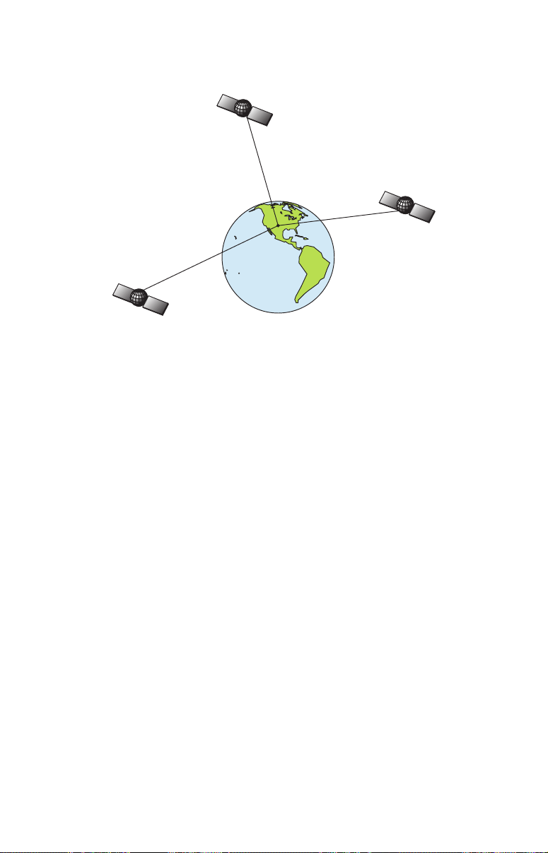
are spares, unused until needed. The rest virtually guarantee that at
least four satellites are in view nearly anywhere on Earth at all times.
A minimum of three satellites are required to determine a 2D fix.
The system requires signal reception from three satellites in order to
determine a position. This is called a 2D fix. It takes four satellites to
determine both position and elevation (your height above sea level —
also called altitude). This is called a 3D fix.
Remember, the unit must have a clear view of the satellites in order to
receive their signals. Unlike radio or television signals, GPS works at
very high frequencies. These signals can be easily blocked by trees,
buildings, an automobile roof, a wing, even your body.
Like most GPS receivers, AirMap doesn’t have a compass or any other
navigation aid built inside. It relies solely on the signals from the satellites to calculate a position. Speed, direction of travel, and distance
are all calculated from position information. Therefore, in order for
AirMap to determine direction of travel, you must be moving and the
faster, the better. This is not to say that it won’t work at walking or
boat trolling speeds — it will. There will simply be more "wandering" of
the data shown on the display.
GPS is plenty accurate for route navigation, but the U.S. Federal Aviation Administration has special needs for aircraft traffic control that go
beyond basic GPS. The FAA has a plan under way to boost GPS performance even further with its Wide Area Augmentation System, or
WAAS. This GPS add-on will include a time control element that will
help airliners fly closer together while avoiding collisions. In addition to
carefully spacing airplanes along travel corridors, WAAS will eventually make instrument landings and takeoffs more accurate as it replaces existing aviation navigation systems.
8
Page 15

WAAS signals make your GPS navigation even more accurate. Your
AirMap automatically receives both GPS and WAAS signals. However,
WAAS has some limits you should know about.
First, the U.S. government has not completed construction of the WAAS
system, so it is not yet fully operational. The ground stations are in
place, but only a few of the needed WAAS satellites have been launched.
WAAS can boost the accuracy of land and marine GPS navigation, but the
system is designed for aircraft. The satellites are in a fixed orbit above the
Equator, so they appear very low in the sky to someone on the ground in
North America. Aircraft and vessels on open water can get consistently
good WAAS reception, but terrain, foliage or even large man-made structures frequently block the WAAS signal from ground receivers.
You'll find that using your GPS+WAAS receiver is both easy and
amazingly accurate. It’s easily the most accurate method of electronic
navigation available to the general public today. Remember, however,
that this receiver is only a tool. As this manual goes to press, the FAA
has not yet certified any hand-held GPS+WAAS receivers for use as the
sole navigation aid for VFR pilots. Always have another method of
navigation available, such as a sectional chart and your aircraft's magnetic and gyro compasses, or a conventional nav/com radio.
Also remember that this unit will always show navigation information
in the shortest line from your present position to an airport, VOR or
other waypoint, regardless of obstacles and terrain! It only calculates
position, it can’t know what’s between you and your destination, for
example. It’s up to you to safely navigate around obstacles and rising
terrain, no matter how you’re using this product.
How to use this manual: typographical conventions
Many instructions are listed as numbered steps. The keypad and arrow
"keystrokes" appear as boldface type. So, if you're in a real hurry (or
just need a reminder), you can skim the instructions and pick out what
menu command to use by finding the boldface command text. The paragraphs below explain how to interpret the text formatting for those
commands and other instructions:
Arrow Keys
The arrow keys control the movement of dotted cross-hair lines on your
mapping screen called the cursor. The arrow keys also help you move
around the AirMap menus so you can execute different commands.
They are represented by symbols like these, which denote the down arrow key, the up arrow, the left arrow and the right arrow: ↓ ↑ ← →.
9
Page 16

Keyboard
The other keys perform a variety of functions. When the text refers to a
key to press, the key is shown in bold, sans serif type. For example, the
"Enter/Save" key is shown as
ENT and the "Menu" key is shown as MENU.
Menu Commands
A menu command or a menu option will appear in small capital letters,
in a bold sans serif type like this:
SYSTEM SETUP. These indicate that you
are to select this command or option from a menu or take an action of
some kind with the menu item. Text that you may need to enter or file
names you need to select are show in italic type, such as trail name.
Instructions = Menu Sequences
Most functions you perform with AirMap are described as a sequence of
keystrokes and selecting menu commands. We've written them in a
condensed manner for quick and easy reading.
For example, instructions for deleting all icons from memory would look
like this:
1. Press
2. Press ← to
3. Press
MENU|↓ to DELETE MY ICONS|ENT|ENT.
YES|ENT.
EXIT.
Translated into complete English, step 1 means: "Press the Menu key.
Next, press the down arrow key to scroll down the menu and select
(highlight) the Delete My Icons menu command. Finally, press the Enter key twice."
Step 2 means: "Press the left arrow key to select Yes, then press Enter."
Step 3 means: "Press the Exit key to clear the menu and return to the
Map Page."
Important Keyboard Shortcut Tip:
There are often three ways to move around an AirMap menu. For
simplicity, we've written our instructions using the Enter key (
to complete a move from one menu to the next. However, many
commands have shortcuts that will help your fingers fly across the
keys. Almost every page menu command lets you press ← or → in-
stead of
(
MAP DATA…) or an arrow (GPS SETUP ►). Our menus also "wrap
ENT. This is always true for commands with an ellipses
around;" that is, they form a circular loop. This means when you
open a menu and need to reach the bottom command, you can get
there by pressing ↑ one time instead of holding or repeatedly
pressing ↓. A cockpit can be a busy place; practice with these shortcuts and you can run AirMap commands faster, with less finger
movement from key to key.
ENT)
10
Page 17

Section 2:
Installation & Accessories
Power
The AirMap operates from AA batteries or on 3 volts DC using an optional external power cable with a cigarette lighter adapter. If the
power cable is used, the AirMap automatically switches to it if the external power is greater than the battery voltage. If the external power
fails, the unit automatically switches to the batteries.
NOTE:
Some pilots like to keep fresh batteries in their units, even when using the external power. If the power fails, the unit will automatically
switch to the batteries, thus keeping the unit on without interruption.
Warning!
With earlier Lowrance Aviation units, some pilots liked to
remove the cigarette lighter plug from the adapter cable
and splice the exposed wires directly to their dash consoles. However, the AirMap 500 cigarette lighter adapter
contains in the plug a voltage regulator to convert 12
volts down to about 3. Without this regulator, connecting
your unit to a 12-volt power source will destroy the unit –
and this damage will not be covered by your warranty.
Flash memory and an internal lithium battery will keep your stored
data safe and accessible for the life of the product.
Batteries
The unit requires two, 1.5 volt AA batteries. We recommend that you
use alkaline batteries for the best trade-off between battery life and
cost. We recommend DURACELL
If you're looking for an extended-life battery, the Duracell
tery has performed well in our tests.
You can also use rechargeable AA alkaline batteries, such as those
made by RAYOVAC
batteries. We do not recommend nickel cadmium (NiCd) rechargeable
batteries because you will get poor battery life.
Rechargeable alkaline batteries will not last as long as standard alkaline batteries. NiMH batteries are rechargeable and should also give
you suitable battery life.
, or rechargeable AA nickel metal hydride (NiMH)
brand, but other brands will work.
11
ULTRA bat-
Page 18
Do not mix different battery types. Mixing battery types may cause leakage. (For example, don’t use both alkaline and NiMH batteries at the
same time, and don't use standard alkalines with rechargeable alkalines.)
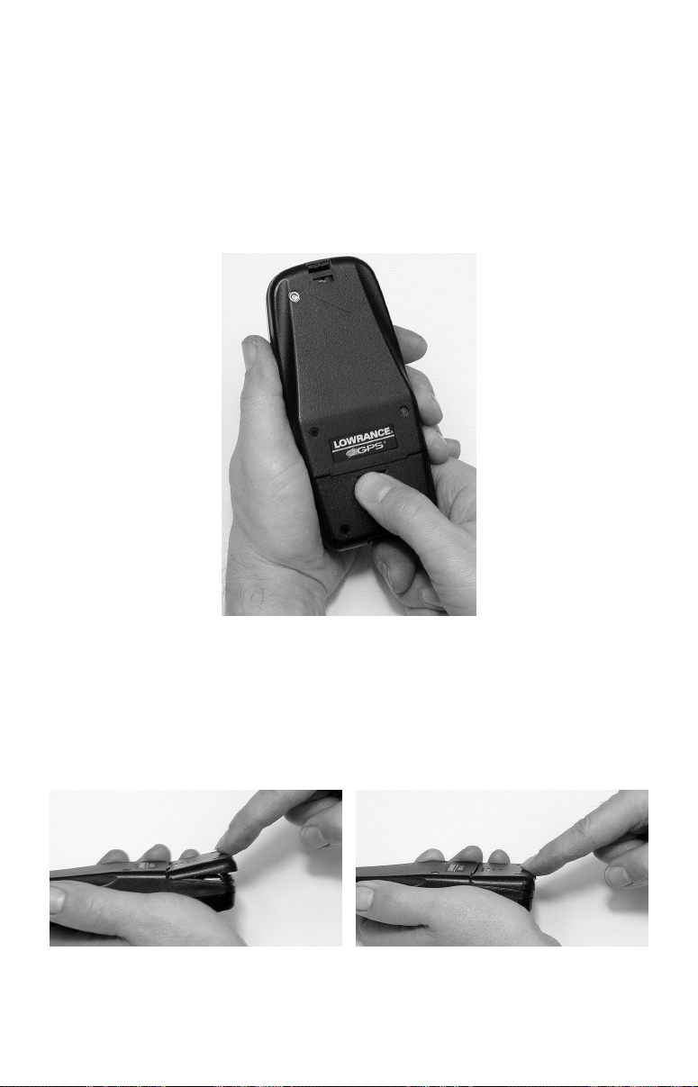
Battery Installation
Turn the unit over so that the back is facing you. Place your thumb on
the large arrowhead on the battery compartment cover. Press in and
down, toward the bottom of the unit (in the direction indicated by the
arrow). The battery cover will snap off.
Remove AirMap battery cover.
Install the batteries according to the decal in the battery compartment,
which shows the correct polarity. Point the positive pole of the upper battery to the left; point the positive pole of the bottom battery to the right.
Replace the battery compartment cover. Align the cover latch tab with
the slot inside the case. With a finger, press the bottom of the cover in
and then up, toward the top of the unit
Replace battery compartment cover. Align
tab with slot, left. Press in cover bottom, right
12
Page 19

Cigarette Lighter Power Adapter
To use external DC power: Plug the power cable's cigarette lighter
adapter into a cigarette lighter receptacle. Next, slide the other connector over the power contacts on the bottom of the AirMap case.
Attach external power cable to AirMap.
MMC or SD Memory Card Installation
Your AirMap uses a MultiMedia Card to store information, such as custom maps, waypoints and other GPS data. The unit can also use Secure
Digital Cards (SD cards) to store information.
NOTE:
Throughout this manual, we will use the term MMC, but just remember that your unit can use an MMC or SD card to store data.
Both of these solid-state flash memory devices are about the size of a
postage stamp. An SD card is slightly thicker than an MMC. As this
manual went to press, MMCs were available in storage capacities of 8
MB, 16 MB, 32 MB and 64 MB. SD cards were available in capacities of
8 MB, 16 MB, 32 MB, 64 MB, 128 MB, 256 MB and up. We have tested
SD cards up to 256 MB.
Additional MMC cards are available from LEI Extras; see ordering information inside the back cover of this manual. MMCs and SD cards
are also available at many consumer electronics stores.
The MMC slot is located in the battery compartment, behind the batteries on the right side of the unit. The battery compartment decal
points out the slot, which is also marked by small white letters on the
circuit board.
To remove an MMC
1. Remove battery compartment cover.
2. Remove batteries, if present.
13
Page 20

3. Hold unit upright in left hand. Use a thumbnail or fingernail to grab
the groove in the bottom of the MMC.
4. Drag the MMC from the slot into the battery compartment.
5. Hold AirMap face up and give it a shake to dump the MMC into your
hand or onto a work surface.
To add an MMC or SD Card
1. Remove battery compartment cover.
2. Remove batteries, if present.
3. Hold unit upside down in left hand. Grasp the bottom corner of the
MMC with your other hand. The MMC label should be toward you.
4. Use the white lines and text on the circuit board as a guide and drop
the MMC into the slot.
5. Gently shake the unit or use your finger to nudge the MMC into vertical alignment. Then, gently push the card into the slot with your finger.
6. Replace the batteries and battery cover.
Aquabag Waterproof Travel Pouch Installation
The waterproof travel pouch keeps your GPS dry when the going gets
wet. An adjustable neck strap on the pouch keeps your unit within
reach. The pouch is made of a transparent material that is rugged, yet
easy to see through. The pouch is flexible enough for you to operate the
AirMap's keys with the unit inside. To use it, open the closure flap and
unroll the anti-moisture baffle to open the bag. Slip the unit inside. Roll
up the baffle and close the outer flap.
Insert AirMap into bag upside down, left. That makes it easier to read
when wearing the unit around your neck, right.
14
Page 21

External Active Antenna
A GPS antenna requires a clear view of the sky for optimum operation.
Inside the cockpit, your AirMap can sometimes maintain satellite lock
while sitting on the seat beside you, but we don't recommend this for
optimum performance.
Since the "view" is restricted to what can be seen through the window,
this operating mode will reduce position accuracy and will increase the
chance of losing satellite lock. Inside a plane, the unit operates best
with an external antenna mounted on the windshield or dash.
Attach AirMap antenna to windshield bracket with two screws.
You may achieve good results by simply placing the external antenna
on the top of the dash, at the base of the windshield. Many pilots like to
attach the antenna to the top of their instrument panel glare shields.
Depending on the surface, a strip of adhesive Velcro
or a piece of the
rubber non-skid shelf liner material available in recreational vehicle
supply stores will help hold the antenna in place.
We recommend attaching the antenna to your windshield or other window. For this reason, the remote active antenna packaged with your
AirMap includes a suction-cup mount. Be sure to mount the antenna in
a location where it will not obstruct your view.
15
Page 22

Press suction cup plate firmly against a window with unobstructed view.
Wherever you mount the antenna, make sure it is in a location with an
unobstructed view of the sky. If you're sticking it to a window, moisten
the suction cups on the mounting plate and press firmly against the
window. Route the cable so that it won't interfere with flying. Then,
simply plug the connector into the unit's antenna socket, located on the
back, in the upper left corner of the case. The AM500 will automatically
switch to use the RAA-3 remote antenna when plugged in.
R-A-M Bracket Mounting System
A R-A-M mounting bracket is shipped with your AirMap. The mounting
arm and cradle can swivel on a ball for easy viewing in any type of vehicle.
Attach the mounting bracket to the stem of the yoke. Then, tighten the
knob at the bracket's base to keep the bracket from sliding around on
the yoke stem. Next, angle the arm so that the unit will be held in front
of the yoke. When you are satisfied with the bracket position, tighten
all the knobs to keep the bracket from shifting.
Find a good position for the R-A-M mounting bracket. Then, slide the
AirMap into the bracket, inserting the bottom of the unit first.
16
Page 23
Section 3:
2
Aviation Operation
This section addresses AirMap's main aviation GPS functions. The
principles are the same in both operating modes, so this discussion also
serves as a good introduction to Land Mode work.
Before you turn on AirMap and find where you are, it's a good idea to
learn about the different keys, the five Page screens and how they all
work together. BUT, if you just can't wait to get outside, grab the batteries and turn to the one-page Quick Reference on page 31.
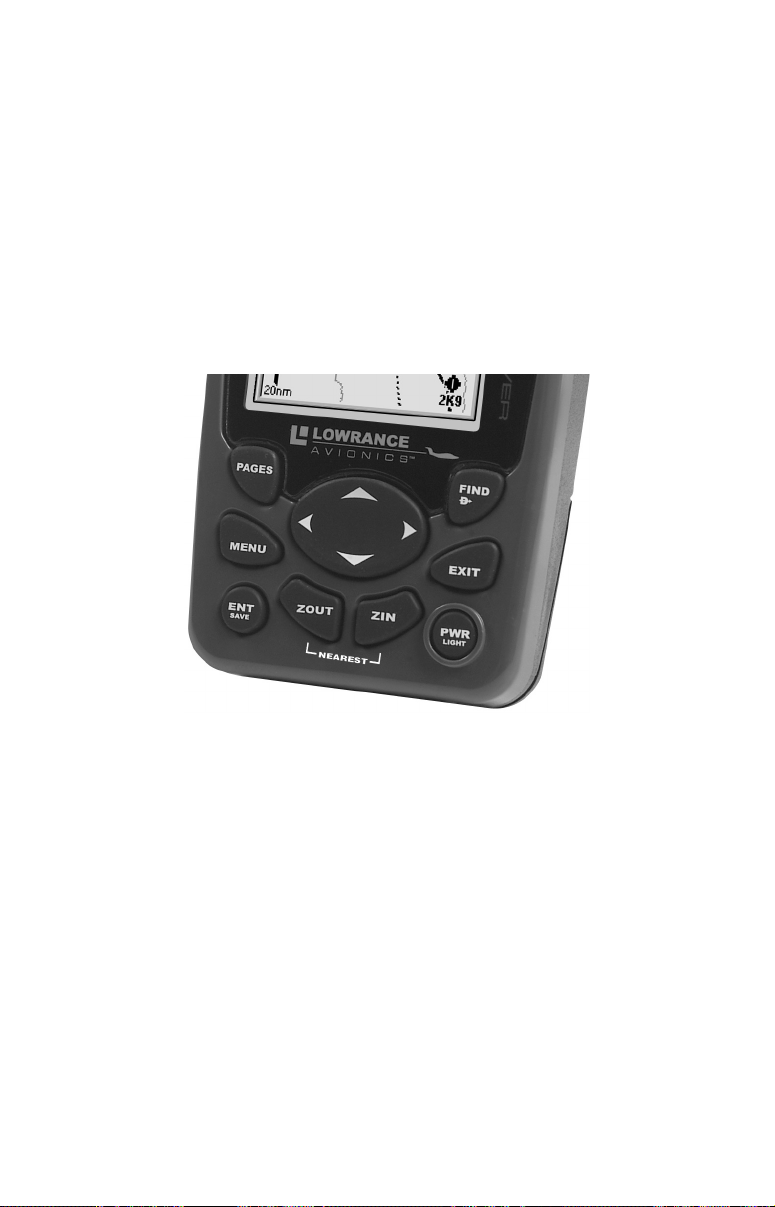
Keypad
7
3
5
1. PWR/LIGHT (Power & Light) – The PWR key turns the unit on and
off and activates the backlight.
2. PAGES – Pressing this key switches the unit between the five different page screens in Aviation Mode. (Satellite, Position, HSI navigation, Map and Airport Orientation.) Each page represents one of the
unit's major modes of operation.
3. MENU – Press this key to show the menus, which allow you to select
or adjust a feature from a list.
4. ARROW KEYS – These keys are used to navigate through the
menus, make menu selections, move the chart cursor and enter data.
5. ENT/SAVE (Enter & Save) – This key allows you to save data, to
accept values or to execute menu commands. Also use it to quickly create waypoints or icons.
8
4
9
AirMap 500 keypad.
17
6
1
Page 24
6. EXIT – The Exit key lets you return to the previous screen, clear
data or erase a menu.
7. FIND
menus. It also allows you to go Direct To items shown in search lists.
8. ZOUT – (Zoom Out) – This key lets you zoom the screen out to see a
larger geographic are on the map. Less detail is seen as you zoom out.
9. ZIN – (Zoom In) – This key lets you zoom the screen in to see greater
detail in a smaller geographic area on the map.
(Direct To) – The Find key launches the AirMap search
Power/lights on and off
To turn on the unit, press PWR. To turn on the backlight, press PWR
again. Pressing PWR once again will turn off the backlight. (Press EXIT
to clear any message or alarm displays.)
Turn off the unit by pressing and holding the
PWR key for 3 seconds.
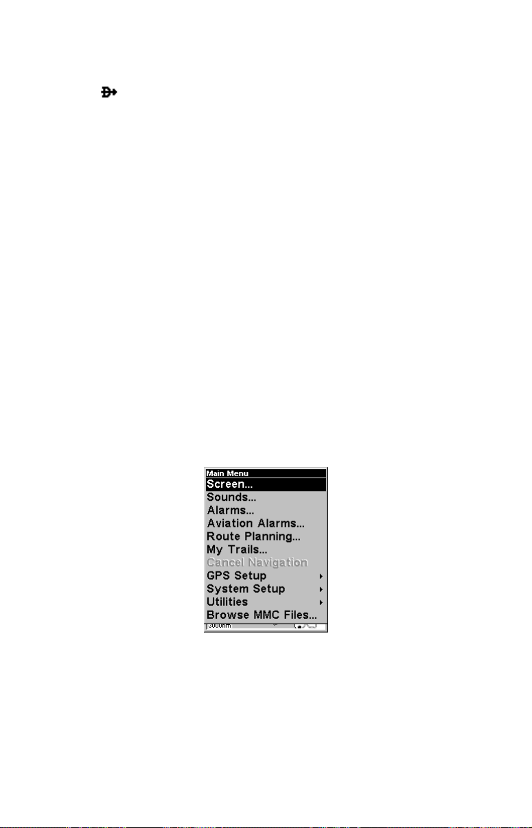
Main Menu
Aviation Mode has a single Main Menu, which contains some function
commands and some setup option commands. The tutorials in this section
will deal only with primary functions, the basic commands that make AirMap do something. These lessons are designed for use with the unit's options set at their factory defaults. But, if you want to learn more about the
various option settings, see Sec. 5, System Setup and GPS Setup Options.
To access the Main Menu from any Page: press
the menu screen and return to the page display, press
Main Menu, Aviation Mode.
The Main Menu commands and their functions are:
Screen command: changes the contrast or brightness of the display
screen.
MENU|MENU. To clear
EXIT.
Sounds command: enables or disables the sounds for key strokes and
alarms and sets the alarm style.
18
Page 25

Alarms command: turns arrival, off course and anchor GPS alarms on
or off and changes alarm thresholds.
Aviation Alarms command: turns distance, time, near and inside airspace alarms on or off and changes alarm thresholds.
Route Planning command: used to plan, view or navigate a route.
My Trails command: shows, hides, creates and deletes plot trails. Also
used to navigate or backtrack a trail.
Cancel Navigation command: turns off the various navigation commands. Used to stop navigating after you have reached your destination navaid, waypoint, Point of Interest or map cursor location; or after
you reach the end of a route or trail.
GPS Setup command: sets various GPS receiver options and runs the
GPS Simulator.
System Setup command: sets general configuration options.
Utilities command: controls several aeronautical calculators and other
time-related utilities. These include: E6B flight computer functions (true
air speed, wind speed, etc.); sun/moon rise calculator; trip status and statistics, alarm clock, up timer and down timer.
Browse MMC Files command: this allows you to view the installed
MMC card and the files it contains.
Pages
Aviation Mode has five Page displays that represent the five major operating modes. They are the Satellite Status Page, the Position Page,
the HSI Navigation Page, the Map Page and the Airport Orientation
Page. They are accessed by pressing the
repeatedly scrolls among the five screens in an endless circular loop.
Each Page has a submenu screen associated with it. You access a Page
Submenu by pressing the
played. (Pressing the
MENU key one time while the page is dis-
MENU key twice takes you to the Main Menu.)
Satellite Status Page
This Page, shown in the following image, provides detailed information
on the status of AirMap's satellite lock-on and position acquisition. To
get to the Satellite Status Page: press
you want appears.
No matter what page you are on, a flashing current position indicator/question mark symbol and flashing GPS data displays indicate that
satellite lock has been lost and there is no position confirmed. This page
shows you the quality and accuracy of the current satellite lock-on and
position calculation.
PAGES key. Pressing PAGES
PAGES repeatedly until the page
19
Page 26
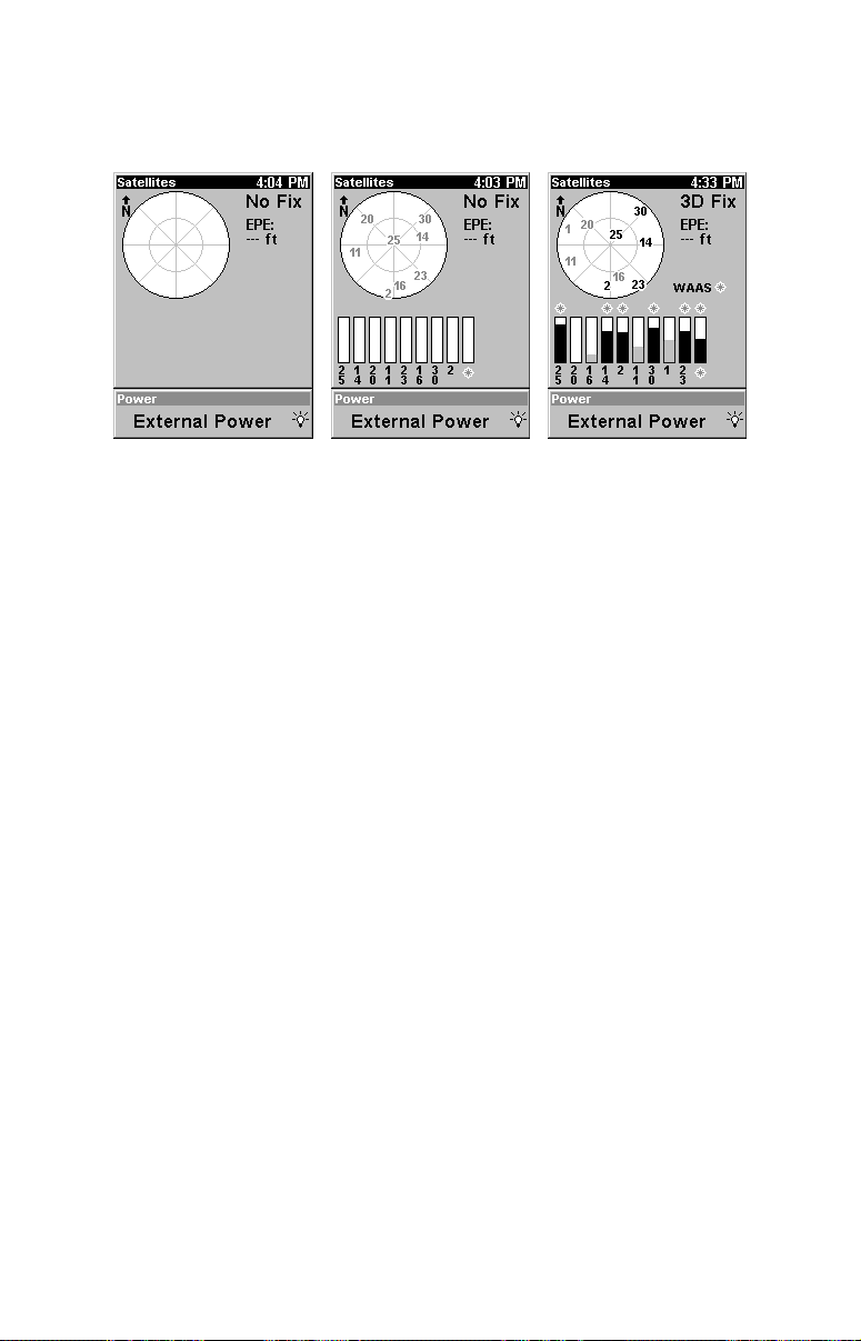
WARNING:
Do not begin navigating with this unit until the numbers
have stopped flashing!
Satellite Page. Left view indicates unit has not locked on to any satellites
and does not have a fix on its position. Center view shows satellites being
scanned. Right view shows satellite-lock on with a 3D position acquired
(latitude, longitude and altitude) and WAAS corrections. The bottom of the
screen shows a battery power indicator with "E" for empty and "F" for full.
The light bulb indicates the backlight is on.
This screen shows a graphical view of the satellites that are in view.
Each satellite is shown on the circular chart relative to your position.
The point in the center of the chart is directly overhead. The small inner ring represents 45° above the horizon and the large ring represents
the horizon. North is at the top of the screen. You can use this to see
which satellites are obstructed by obstacles in your immediate area if
you hold the unit facing north.
The GPS receiver is tracking satellites that are in bold type. The receiver hasn't locked onto a satellite if the number is grayed out, therefore it isn't being used to solve the position.
Beneath the circular graph are the bar graphs, one for each satellite in
view. Since the unit has twelve channels, it can dedicate one channel
per visible satellite. The taller the bar on the graph, the better the unit
is receiving the signals from the satellite.
The EPE, "Estimated Position Error" (horizontal position error) shown
in the upper right corner of the screen is the expected error from a
benchmark location. In other words, if the EPE shows 50 feet, then the
position shown by the unit is estimated to be within 50 feet of the actual location. This also gives you an indicator of the fix quality the unit
currently has. The smaller the position error number, the better (and
more accurate) the fix is. If the position error flashes dashes, then the
unit hasn't locked onto the satellites, and the number shown isn't valid.
20
Page 27
The Satellite Status Page has its own menu, which is used for setting
various options. (Options and setup are discussed in Sec. 5.) To access
the Satellite Status Page Menu, from the Status Page, press
MENU.
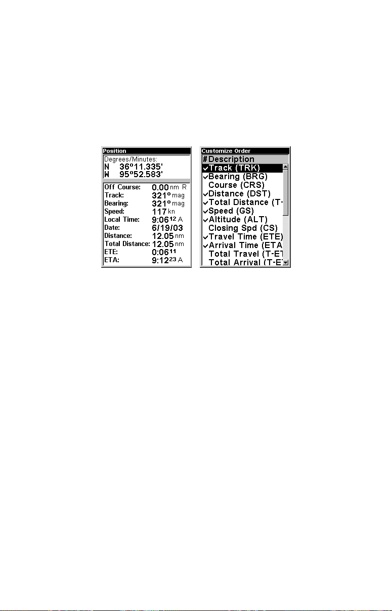
Position Page
This page provides detailed textual information on your present position and
the status of your trip. For example, it can display information such as your
current latitude, longitude, travel time to destination and more. To get to the
Position Page: press
PAGE repeatedly until the page you want appears.
Position Page, left, Position Page Customize Menu, right.
The Position Page can be fully customized. The lower window can display
ten of 22 types of navigation information. For customization instructions
see the Customize Page Displays topic in Sec. 5, System and GPS Setup
Options. Some of the popular information displays include:
Altitude is height above sea level, not ground level. Speed (ground
speed) is the velocity you are making over the ground. Closing Speed
is also known as velocity made good. It's the speed that you're making
toward a destination.
Distance shows how far it is to the next waypoint you're navigating
toward. Total Distance tells how far to a final destination when navi-
gating a route or trail. If your route has multiple legs, this option will
total them for you.
Travel Time (ETE) is the time it will take to reach your destination at
your present closing speed. Arrival Time (ETA) is the local time that
it will be when you arrive at the destination, based upon your present
closing speed and track. Total Travel time tells how long it will take to
reach a final destination when navigating a route or trail.
Track is the heading, or the current direction you are actually traveling.
Bearing is the direction of a line-of-sight from your present position to a
destination. No matter what direction you are steering, the Bearing
21
Page 28
shows the compass direction straight to the destination from your loca-
aircraft
tion at the moment. Off Course tells you how far you are to the left or
right of the intended direction or line of travel toward a destination.
Most of the unit's displays show Off Course as "Cross Track" or "XTK."
The Position Page has its own menu, which is used for setting various
options. (Options and setup are discussed in Sec. 5.) To access the Position Page Menu, from the Position Page, press
MENU.
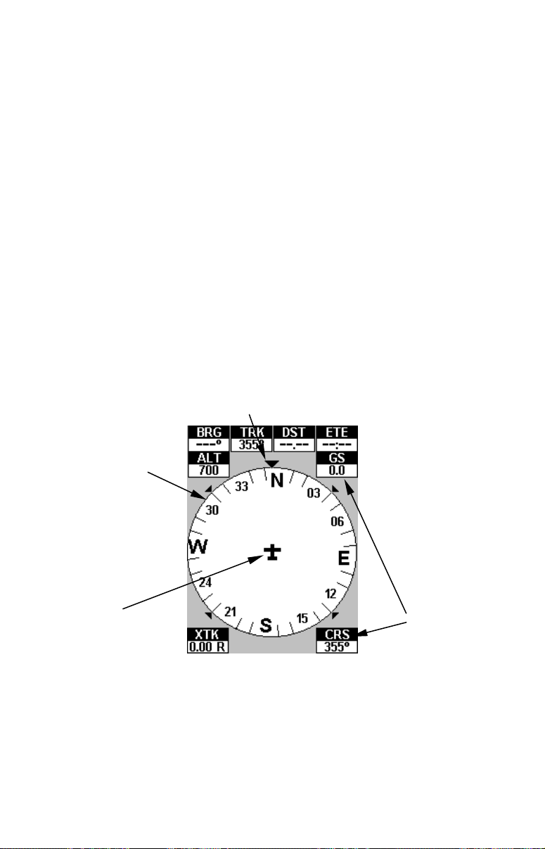
HSI Navigation Page
The HSI (Horizontal Situation Indicator) Navigation Page has a compass
rose. It shows your direction of travel and the direction to a recalled waypoint or other destination, such as an airport or VOR. It can also show your
intended course and whether or not you are on course or off course. To get
to the HSI Page: press
PAGE repeatedly until the page you want appears.
The navigation screen looks like the one in the following image when
you're not navigating to a waypoint or other destination. No graphic course
information is displayed. Your position is shown by an airplane symbol in
the center of the screen. The arrow pointing down at the top of the compass
rose indicates the current track (direction of travel) over the ground.
Track or compass heading indicator, showing direction of travel
Compass rose
Present
position
HSI Navigation Page, traveling north. Page looks like this when AirMap is
not navigating to a waypoint, following a route, or backtracking a trail.
Navigation
information
displays
When navigating to a waypoint or following a route, the HSI screen
looks like the one shown in the next image. Navigation information
such as bearing, track and course can be shown in text displays.
22
Page 29
Tip:
aircraft
arrow
Cross track error
Course arrow
You can fully customize the upper text displays, and there are 26
types of information to select from. For customization instructions
see the Customize Page Displays topic in Sec. 5, System and GPS
Setup Options.
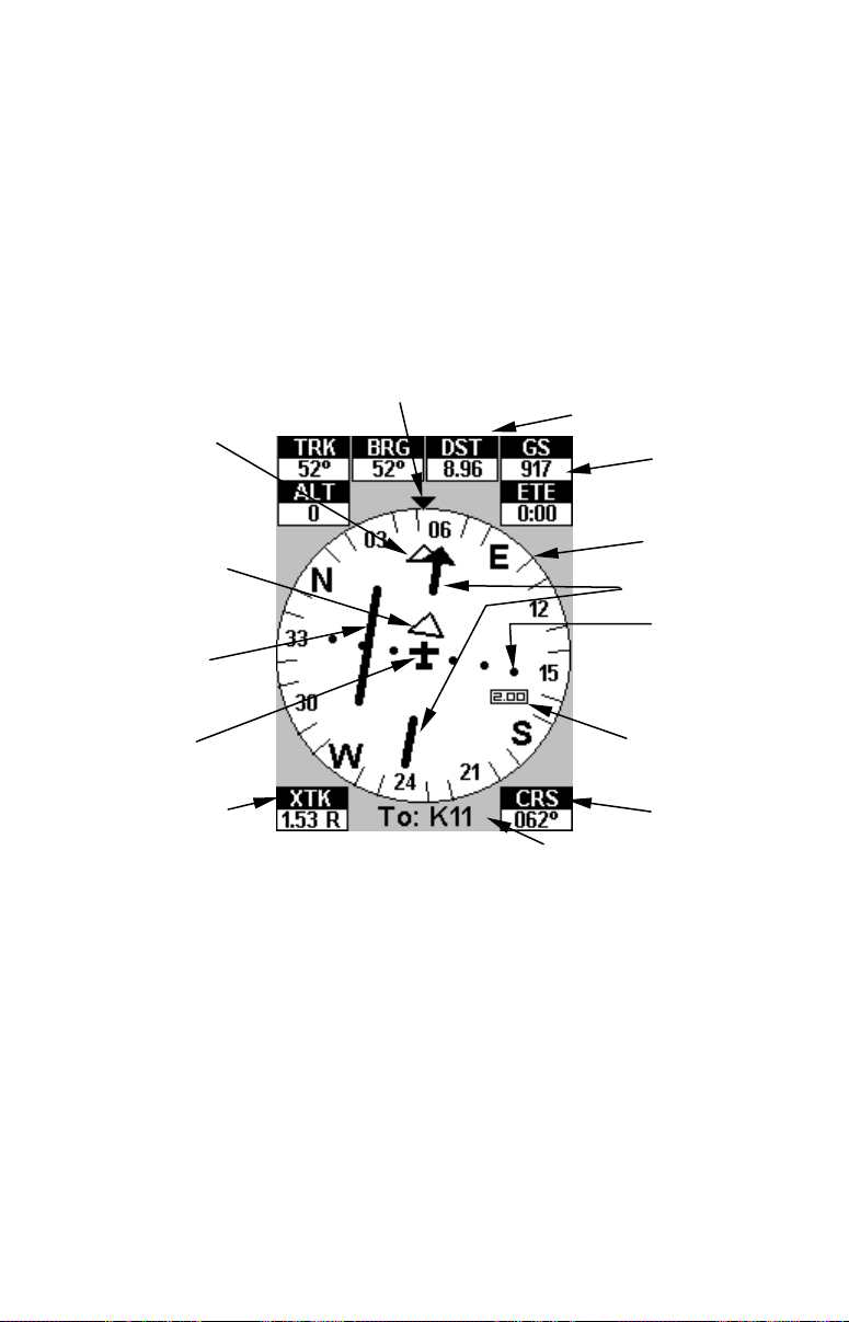
The heart of this page is the Course Arrow with its Course Deviation
Indicator (CDI) needle. It gives you a quick, easy to read visual indicator of the relationship between your current direction (track) and desired direction (course). Pilots familiar with "fly to the needle" VOR instruments or large in-panel GPS screens will quickly feel comfortable
with this HSI feature.
Track or compass heading indicator, showing direction of travel
Bearing arrow
(pointing to
destination)
Distance to waypoint
Ground speed
Navigating
TO waypoint
Course Deviation
Indicator needle
(CDI)
Present
position
Destination name
HSI Navigation Page, flying TO K11 on a course of 62º. The pilot needs
to turn left to "center the needle" and get on course. The plane is cur-
rently 1.53 nautical miles to the right of the course. The cross track
error range is set at 2.00 nautical miles. The flight is 8.96 nautical miles
from the target waypoint.
Compass rose
Cross track
error scale
Cross track
error range
Course
The course line is an imaginary line drawn from your position when
you started navigating to the destination waypoint. It's shown on the
HSI screen as a segmented course arrow. The cross track error is the
distance you are off-course to the side of the desired course line. The
current cross track error is shown in a text box (XTK), and graphically
by the CDI needle, which is the middle segment of the course arrow.
Dots on either side of the course arrow show the current cross track
error scale, which is a graphic depiction of the cross track error range.
23
Page 30
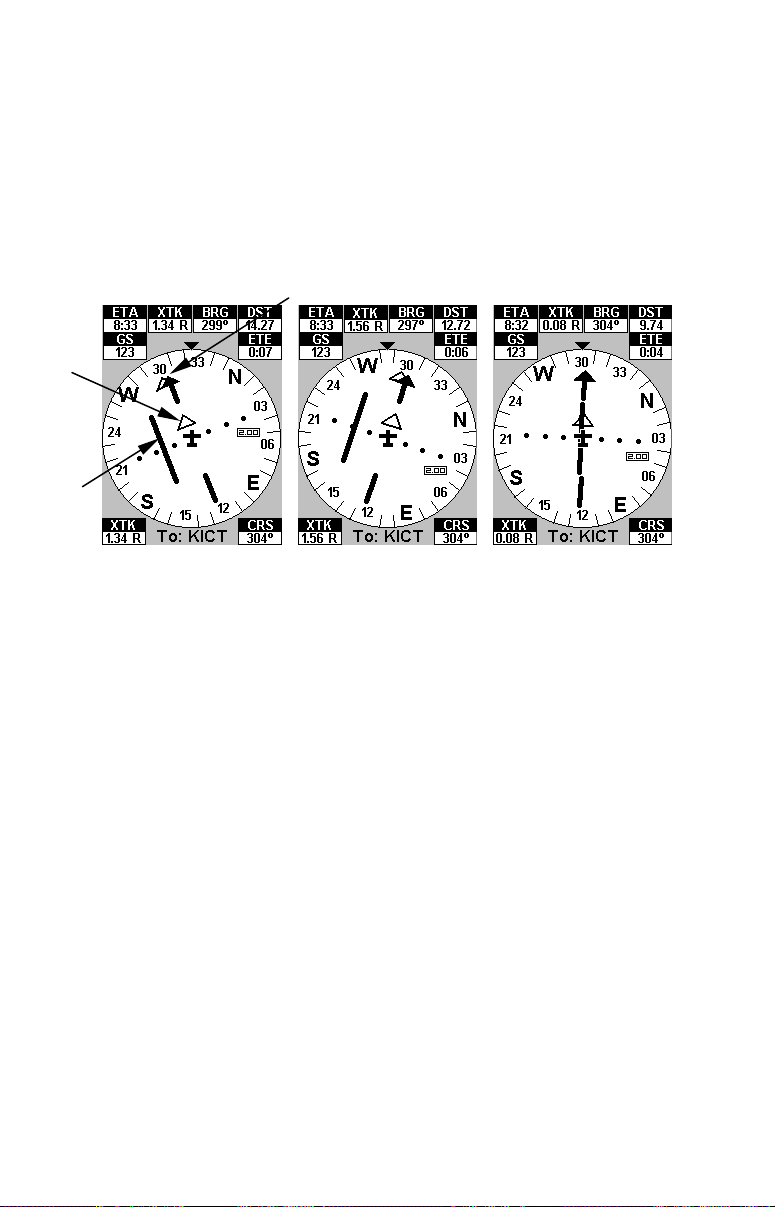
The default for the cross track error range is 2.0 nautical miles, which
arrow
needle
arrow
is shown in a floating text box under the scale. If you veer 2 nautical
miles to the left or right of the course, the off course alarm will appear.
If you are off course to the right, the range box floats to the right of the
course line. If you are off to the left, the range box appears to the left of
the course arrow. You can use the
ZIN or ZOUT keys to change the cross
track error range.
Course
Fig. 1
TO
CDI
Fig. 2 Fig. 3
Following a course by "chasing the needle." Fig. 1, plane has veered off
course to the right by 1.34 nautical miles, away from the needle. Fig. 2,
pilot turns on heading of 297º, steering left toward CDI needle to intersect intended course. Fig. 3, pilot has intercepted his route and is
virtually on course.
The most important graphic element, however, is the CDI needle. The
CDI and the cross track error scale instantly show you the distance to
the course line, as well as the direction to steer to get back on course. In
the example above, fig. 1 shows the pilot off course to the right, so the
CDI needle appears to the left of the plane symbol. Fig. 3 shows the pilot back on course, so the CDI needle appears to line up with the course
arrow. If you steer toward the CDI needle line, you'll always be heading
in the correct direction to get back on course.
NOTE:
The examples above all show navigation to a waypoint, the most common method of GPS navigation. To show navigation from a waypoint,
see the instructions on the OBS Hold feature later in this section.
The HSI Navigation Page has its own menu, which is used for some
advanced functions and for setting various options. (Options and setup
are discussed in Sec. 5.) To access the HSI Page Menu: from the HSI
Page, press
MENU.
24
Page 31

Navigating with OBS Hold
AirMap contains an OBS Hold feature to help you navigate along a radial
from a location. You must first turn on navigation to a location before you
can access OBS Hold. While running a route or navigating to a waypoint,
you launch OBS Hold from the HSI Page; just press the right or left arrow
to initiate it.
NOTE:
You must be navigating to some destination to begin using OBS
Hold. Usually this will be a VOR, or some other Aviation Waypoint
in the Jeppesen database. See the entry Searching later in this section if you need help finding and setting up navigation to a waypoint.
In the example below, Air Traffic Control contacts the pilot flying south
across Oklahoma and warns him of a dangerous storm ahead. To avoid it,
they instruct him to fly out on a radial of 235° from the nearby VOR "ADH."
To use OBS Hold:
1. From the HSI Page, while navigating to something, press ← or →.
2. A window will pop up asking you if you want to activate OBS Hold.
Press ←|
ENT. Use ← or → to change the OBS Hold radial until it
reaches the angle you need. Press ← to decrease the angle, press → to
increase it.
OBS Hold
data box
Left, pilot navigating to VOR. Center, HSI Page with OBS Hold menu.
Right, HSI Page with OBS Hold activated. Note data box in the
bottom right corner showing OBS direction instead of Course. This
image shows the pilot has passed the VOR and is flying from it.
The navigation data will now begin showing directions along the OBS radial instead of toward your original destination. The white arrow behind
the airplane icon indicates you are navigating FROM a waypoint. Remember that you can change the radial of OBS Hold using the right and
left arrow keys. Press ← to decrease the angle, press → to increase it.
25
Page 32

Use the Clear OBS Hold command to resume navigation. The HSI
Navigation displays will point to your original destination again. At
right, you can see the pilot's diversion in his trail on the map page.
You can turn off OBS Hold at any time using the HSI Page menu. Press
MENU|↓ to CLEAR OBS HOLD|ENT. The navigation data will once again
direct you to your destination, or the next waypoint in the route you're
navigating. Beginning navigation to a new destination will automatically
clear OBS Hold, as well.
Map Page
The map screens (including the Airport Orientation Page) show your
course and track from a "bird's-eye" view. By default, this unit shows
the Map Page map with north always at the top of the screen. (This can
be changed using options described in the topic Map Orientation, in
Sec. 5.) If you're navigating to a waypoint, the map also shows your
starting location, present position, course line and destination.
NOTE:
When our text says "navigating to a waypoint," we really mean navigation to any selected item, whether it is a waypoint you made, a
map feature or an item (like a VOR) from the Jeppesen database.
Using the map is as simple as pressing the
PAGES key. A screen similar to
those in the following images appears. The aircraft in the center of the
screen is your present position. It points in the direction you're traveling. A
solid line extending from the plane's tail is your plot trail, or path you've
taken. (Remember, a flashing question mark on you plane symbol or
flashing text displays means AirMap has not yet calculated a position.)
The map zoom range is the distance across the screen. This number
shows in the lower left corner of the screen. In the first example below
left, the range is 4,000 nautical miles from the left edge of the map to
the right edge of the map.
26
Page 33

Far left, Map Page opening screen. Center, zoomed to 100 nautical miles
and right, zoomed to 6 nautical miles. (Note that the four data boxes ap-
pearing in the bottom of these images are on by default. They have been
turned off in most of the following images for the sake of clarity.)
The Zoom In and Zoom Out keys zoom the map to enlarge or reduce its coverage area and the amount of mapping detail shown. There are 39 available
map zoom ranges, from 0.02 nautical miles to 4,000 nautical miles.
AirMap's high resolution screen makes it possible to display aeronautical
chart features that look like the "real thing." If you're familiar with sectional
charts, you will instantly recognize items such as obstacles, VORs, special
airspaces, paved and unpaved airports and more. As you zoom in closer,
you'll see Class B airports appear at a fairly wide zoom. Zoom in closer and
Class C and D airports appear, as well as restricted airspaces. At closer
zooms still you can even see Class C airspace borders around airports.
If you're using only the factory-loaded background map, the maximum
zoom range for showing additional land map detail is 6 nautical miles. You
can continue to zoom in closer, but the map will simply be enlarged without
revealing more map content (except for a few major city streets.) Load your
own high-detail custom map made with MapCreate, and you can zoom in to
0.02 nautical miles with massive amounts of accurate map detail.
Map Pages with high-detail map of an urban area loaded on the MMC.
At left, arterial streets appear at the 4 nautical mile zoom range. At 1
nautical mile, minor streets appear, along with square dots representing Points of Interest. Right, at the 0.4 nautical mile zoom, you can see
an interstate highway with an exit, major and minor streets as well as
Point of Interest icons for two hotels and two restaurants.
27
Page 34

Background map vs. MapCreate map content
The background map includes: low-detail maps of the whole world (containing cities, major lakes, major rivers, political boundaries); and medium-detail maps of the United States.
The medium-detail U.S. maps contain: all incorporated cities; county
boundaries; some major city streets; Interstate, U.S. and state highways;
Interstate highway exits and exit services information; large- and medium-sized lakes and streams; and more than 60,000 navigation aids and
10,000 wrecks and obstructions in U.S. coastal and Great Lakes waters.
MapCreate custom maps include massive amounts of information not
found in the background map. MapCreate contains: the searchable
Points of Interest database, all the minor roads and streets, all the
landmark features (such as summits, schools, radio towers, etc.); more
rivers, streams, smaller lakes and ponds and their names.
What's more important is the large scale map detail that allows your
GPS unit to show a higher level of position accuracy. For example, the
background map would show you the general outline and approximate
shape of a coastline or water body, but the higher detail in MapCreate
shows the shoreline completely and accurately (finer detail). Many
smaller islands would not be included in the background map, but are,
of course, in MapCreate.
Cursor lineInterstate Major Street
POI
Markers
School POI
Zoom
Range
When the map is zoomed out far enough, most POIs appear as square dots.
As you zoom in closer, the symbols become readable icons. In the 0.2 nau-
tical mile zoom example at right, the cursor has selected the Cupps Café
POI, which triggers a pop-up box with the POI name. This pop-up box
works on POIs at any zoom range.
POI
Pop-up
Restaurant
POI
Position,
distance and
bearing data
28
Page 35

Tip:
In some urban areas, businesses are so close to one another that
their POI icons crowd each other on the screen. In the preceding
figure, you can see a packed string of POIs all along the west half of
11th. You can reduce screen clutter and make streets and other
map features easier to see by simply turning off the display of POIs
you're not watching for. (To see how, check the text on Map Detail
Category Selection, in Sec. 5. It shows how to use the Map Categories Drawn menu to turn individual POI displays off and on.) Even
though their display is turned off, you can still search for POIs and
their icons will pop-up when your unit finds them for you.
NOTE:
On the Map Page, the screen shows an indicator of what AirMap's
microprocessor is doing behind the scenes. In the lower right corner
of the screen, an MMC icon will flash when the AirMap is reading information from the MMC.
1. To get to Map Page: Map page is the default when AirMap is turned
on. To switch from another page to the Map Page, press
edly until the page you want appears.
PAGE repeat-
2. To get to Map Page Menu: press
MENU.
Map Menu.
Map Page Menu
The map menu has many options. It allows you to get information on
the airspace you're in with the Airspace Status command. You can also
find distances, change the orientation of your map, view map data, and
other helpful map functions. Read more about these functions in Sec. 5,
System Setup and GPS Setup Options.
Airport Orientation Page
The Airport Orientation Page is a special version of the Map Page. This
page only appears when you are navigating to an airport that has run-
29
Page 36

way position information listed in our database. Then, when you press
PAGE from the Map Page, it will switch to a split map, showing your
current position in the top map, and a zoomed view of the destination
airport in the bottom map. Both maps are always in "Track Up" mode.
There are several unique features built into the Airport Orientation
Page. You will notice in the following image that we have added four
customizable information displays on the left side of your position map.
The default options are intended to help in navigating to a landing.
In fact, everything about this page is intended to help you navigate to a
landing. The top position map is locked so that it will always show your
location relative to the destination airport. It is permanently in auto zoom,
so it will zoom in or out to keep you and the airport both on the screen.
The bottom airport map is not locked. You can scroll the cursor to look for
obstructions or known landmarks on the map. You can zoom it in or out to
get better detail or wider perspective. And, like the Map Page, pressing
EXIT will snap the map back to its starting point – but now it returns to
center on the airport, so you can always easily check your approach.
The Airport Orientation Page, showing an approach to
Tulsa International Airport.
We've done everything we could with AirMap to make it a powerful
navigation tool, but also to keep it simple to use. Sometimes describing
all of the options AirMap contains can make it sound hard to use, but
it's really not!
The following page contains a 12-step quick reference for the most basic
aviation GPS operations. If for some reason you don't want to carry the
manual with you as you practice with the AirMap, you might consider
photocopying this quick reference page and tucking it into your pocket
or flight bag.
30
Page 37

Aviation GPS Quick Reference
Start outdoors, with a clear view of open sky. Imagine you're flying to a
nearby airport to practice landings. (If you're practicing on foot or by car,
substitute a restaurant for an airport. Pick one a few blocks away. While
learning, navigation in too small an area constantly triggers alarms.
1. Insert the MMC and batteries. Mount AirMap on the yoke. Connect to
electric power and the active antenna. (See install details on page 11.)
2. Turn on the AirMap: press and release
each of the two warning and copyright message screens.
3. Opening screen– displays map of North America at the 4,000 nautical
mile zoom range. Rotate through four main Page screens (Map Page, Satellite Status Page, Position Page and HSI Navigation Page) by repeatedly
pressing
PAGES key. Switch pages to display Satellite Status Page.
4. Wait while unit locates satellites and calculates current position. Process
is visible on Satellite Page. This takes an average of 1 minute or less with
sky unobstructed by terrain or structures. When the unit acquires position,
a tone sounds and a position acquired message appears.
5. With position acquired, press
PAGES key to display Map Page, which
shows a bird's eye view of the earth. You can move around the map by:
Zoom in closer to see greater detail: press
Zoom out to see more area, less detail: press
Scroll map north, south, east or west using arrow keys ↑ ↓ → ← .
To stop scrolling and return to current position on map, press
6. At the airport, set a waypoint (Wpt 001) at your current position so
you can navigate back here: press
"001" appears.
7. Zoom/scroll map to find a nearby airport to go to. Use arrow keys to
center cursor cross-hair over the airport symbol or wherever you want
to enter the pattern.
8. Navigate to airport: press
MENU|↓ to GO TO CURSOR|ENT|EXIT, and take
off. Follow dotted course line on Map Page or Course Arrow on HSI Navigation Page. (Remember to "steer to the needle.")
9. At airport, Arrival Alarm goes off; to clear it, press
and land. Cancel navigation: press
TION
|ENT|← to YES|ENT.
10. Return to Wpt 1 by Navigate To Waypoint: press
WAYPOINTS|ENT|ENT. Use ↑ or ↓ to select Wpt 001, press ENT|ENT; follow
navigation displays.
11. Back home, Arrival Alarm goes off; press
press
MENU|MENU|↓ to CANCEL NAVIGATION|ENT|← to YES|ENT.
12. To turn off AirMap, press and hold
31
PWR key. Press EXIT to clear
ZIN (zoom in key.)
ZOUT (zoom out key.)
EXIT key.
ENT|ENT. Waypoint symbol and
EXIT. Enter pattern
MENU|MENU|↓ to CANCEL NAVIGA-
FIND|↓ to MY
EXIT. Cancel navigation:
PWR key for three seconds.
Page 38

Find Your Current Position
Finding your current position is as simple as turning AirMap on. Under
clear sky conditions, the unit automatically searches for satellites and
calculates its position in approximately one minute or less.
NOTE:
"Clear sky" means open sky, unobstructed by terrain, dense foliage
or structures. Clouds do not restrict GPS signal reception.
If for some reason satellite acquisition takes longer, you may be inside
a structure or vehicle or in terrain that is blocking signal reception. To
correct this, be sure you are positioned so that the unit has as clear a
view of the sky as possible, then turn the unit off and back on again.
Moving Around the Map: Zoom & Cursor Arrow Keys
The map is presented from a bird's eye view perspective. The current
zoom range shows in the lower left corner of the screen.
1. Press the
ZIN key (zoom in) to move in closer and see greater detail in
a smaller geographic area.
2. Press the
ZOUT key (zoom out) to move farther away and see less map
detail, but a larger geographic area.
When you are walking or riding in a vehicle, the map will automatically
move as you move. This keeps your current location roughly centered
on the screen.
You can manually pan or scroll the map northward, southward, eastward or westward by using the arrow keys, which launches the crosshair map cursor. This allows you to look at map places other than your
current position. To clear the cursor, press
back to the current position or the last known position.
Selected airport
EXIT, which jumps the map
Cursor line
Cursor line
Distance
measured
by cursor
The selected airport to the northwest is 3.66 nautical miles away.
Tip:
Use the cursor to determine the distance from your current position
(or last known position, when working indoors) to any map object or
location. Simply use the arrow keys to position the cursor over the
32
Page 39

object or place. The distance, measured in a straight line, appears in
the data box at the bottom of the map. Press
EXIT to clear the cursor.
Selecting Any Map Item With the Cursor
1. Use the zoom keys and the arrow keys to move around the map and
find the item you wish to select.
2. Use the arrow keys and center the cursor cross-hair on the desired object. On most items, a pop-up box will give the name of the selected item.
You will also notice a black ring surrounds the item as it becomes selected. Once that happens, if you press
with an extra option at the top of the list:
FIND the Find Menu will pop up
SELECTED ITEM. Press ENT to see
the Information screen for the selected item.
Searching
Now that you've seen how AirMap can find where you are, let's search
for something somewhere else. Searching is one of the most powerful
features in the Lowrance GPS product line.
In this example, we'll look for the nearest VOR. For more information
on different types of searches, refer to Sec. 6, Searching.
NOTE:
This example requires the Jeppesen database included with your AirMap.
After AirMap has acquired a position:
1. Press
FIND|↓ to FIND VORS|ENT.
2. You could search the VOR category by any of these four criteria (by
Nearest, by Name, by Identifier or by City), but in this example we will
just search for nearest. When the Find By menu pops up, press
ENT.
3. AirMap says it is calculating, then a list of VORs appears, with the
closest at the top of the list, and the farthest at the bottom of the list.
The nearest is highlighted.
Find VORs Menu, left; Search Criteria menu, center; and
list of the nearest VORs, right.
33
Page 40

4. If you wish, you could scroll ↑ or ↓ here to select another VOR, but
for now we will just accept the nearest one. Press
ENT.
5. The waypoint information screen appears. If you wanted to navigate
there, you press
just want to see it on the map, so press → to
ENT, since the GO TO command is highlighted. But we
FIND ON MAP|ENT.
Waypoint information screen on VOR nearest this position. Screen
shows name, identifier, city, radio frequency, latitude/longitude and its
compass bearing. It also shows both distance to the VOR and your "Ra-
dial From" – information ready at your fingertips when Air Traffic Con-
trol wants a position report! The figure at left shows Go To command;
right figure shows Find On Map command.
6. AirMap's map appears, with the cross-hair cursor highlighting the
VOR's symbol. A pop-up name box identifies the VOR. A data box at the
bottom of the screen continues to display the location's latitude and
longitude, distance and bearing.
Map screen showing Finding Waypoint,
the result of a VOR search.
7. To clear the search and return to the last page displayed, press
EXIT|EXIT|EXIT. (Before you completely exited out of the Search menus,
you could have gone looking for another place.)
NOTE:
Search works from mapping data loaded in AirMap. Aviation Navigation searches also use information from a Jeppesen database, and
34
Page 41

General Navigation searches use POI information available with a
MapCreate custom map. If you do not have a high-detailed Jeppesen map (or a custom map containing POI data) for the area you
are searching loaded on the MMC, you may not find anything.
Find Nearest Airport (shortcut)
One of flying's most terrifying events is having to make an emergency
landing. This situation can be deadly at any time. It's particularly dangerous when you're flying over unfamiliar territory, with no idea where
you can safely stop. Of course, the first thing to do is remain calm and
follow all standard emergency procedures. Naturally, no instrument by
itself can get you through an emergency situation, but we have done
our best to provide you with the tools you need as a pilot.
One of these emergency tools in the AirMap is a Find Nearest Airport
feature that automatically locates, selects, and shows navigation data
to the airport nearest the location where the feature was activated. To
activate Find Nearest Airport, press the
ZOUT and ZIN keys at the same
time. A Find By Nearest screen appears, showing a list of the closest
airports. Use ↑ or ↓ to select the best airport for your situation. Then
you can press
press
to begin navigating to the selected location.
ENT to get detailed information about the airport, or
Navigating to Nearest Airport with the AirMap
Find your way to the selected airport with the HSI Navigation Page or
Map Page. Any time navigation is activated, the HSI Navigation Page
shows the compass rose with its bearing arrow pointing toward the desired
destination position, and the destination name shown below. The Map
Page displays a dotted line from your start point to the desired airport, and
the Airport Orientation Page shows your position in the top map, and the
position and orientation of the selected airport in the bottom map.
Tip:
You don't need to have an emergency to use the Find Nearest Airport feature. You can also use it to maintain positional awareness
by finding the nearest landing strip at any time.
To cancel navigation to Nearest Airport, press
NAVIGATION|ENT|← to YES|ENT. AirMap stops showing navigation in-
formation.
Setting a Waypoint
A waypoint is simply an electronic "address," based on the latitude and
longitude of a position on the earth. Both the Aviation and the Land
mode allow you to save waypoints to mark specific locations you'd like to
35
MENU|MENU|↓ to CANCEL
Page 42

return to (or maybe send a friend to, or even specifically avoid). To save a
waypoint: 1. Press and release
pears, with the
QUICK SAVE method selected. To place a waypoint at your
current cursor position, press
ENT. 2. The CREATE WAYPOINT menu ap-
ENT. The waypoint icon appears on the
map, and a pop-up box tells you the waypoint's name (in this case, "001."
Pop-up box
Create a waypoint. The pop-up box with waypoint name is shown at left.
At right, you can see Waypoint 001, with the default waypoint symbol.
This example shows a waypoint set at the cursor location. If the cursor
was not active, the point would be placed at the current position.
Navigate Back to a Waypoint
To navigate to a waypoint that you've created:
1. Press
the list the waypoint you want to navigate to, then press
FIND|↓ to MY WAYPOINTS|ENT|ENT. Press ↑ or ↓ to select from
ENT. Use the
navigation arrows on the Map Page or the compass rose on the HSI
Navigation Page to make your way to the selected waypoint.
To cancel navigation, press
to
YES|ENT. AirMap stops showing navigation information.
MENU|MENU|↓ to CANCEL NAVIGATION|ENT|←
Navigate to Cursor Position on Map
The Go To Cursor command navigates to the current cursor position
on the map.
To navigate to a particular location on the map, find location, then select
the location with cursor. Use the Go To Cursor command to lead you there:
1. Use the cursor (controlled by the arrow keys) with the zoom in and
zoom out keys to maneuver around the map until you find a location
you want to go to.
2. Center the cursor over the location to select it. If you have selected a
location that contains navigation information, the icon you're pointing
at will be highlighted, indicating it's selected. See the example below.
36
Page 43

Navigate to cursor. In this example, the cursor has selected
the town of Oologah, Oklahoma.
3. Press MENU|↓ to GO TO CURSOR|ENT and AirMap will begin navigating to the cursor location.
The Map Page will display a dotted line from your current position to
the cursor position. The HSI Navigation Page displays a compass rose
showing navigation information to your destination. See examples in
the following images.
The 15- nautical mile zoom figure at left clearly shows the dotted
course line connecting your current position to your destination. The
40- nautical mile zoom, center, shows both current position and desti-
nation on screen. The HSI Navigation Page, right, will also show navi-
gation information.
To stop navigating to the cursor, use the Cancel Navigation command:
press
MENU|MENU|↓ to CANCEL NAVIGATION|ENT|← to YES|ENT. AirMap
stops showing navigation information.
Navigate to a Point of Interest
AirMap can navigate to any Point of Interest (POI) you can look up
with the
FIND key. (For help with FIND's searching capabilities, see the
entry on Searching earlier in this section, or turn to Sec. 6, Searching,
for detailed instructions.)
37
Page 44

After you have looked up an item with the find command, use the ← to
make sure the
then press
To cancel navigation, press
to
YES|ENT. AirMap stops showing navigation information.
GO TO command is highlighted at the bottom of the screen,
ENT. AirMap begins showing navigation information to the item.
MENU|MENU|↓ to CANCEL NAVIGATION|ENT|←
Go "Direct To" (Using the Direct To Button)
You will notice a symbol on your
this:
. In addition to launching searches, the Find/Direct To button
FIND button that looks something like
also serves several other purposes, depending on when it is used.
For instance, you can use the Direct To shortcut in searches. Let's say
you've done a search for nearest VOR, and a long list of VORs appears. You
scroll through the list and select the one you want to navigate to. Instead of
pressing
ENT (which would bring up an information screen), if you press
it will automatically begin navigating to the selected item in the list.
You can also use Direct To when navigating a route, to force AirMap to
navigate toward a particular waypoint in the route. To do this (from the
Map Page), press
MENU|MENU|↓ to ROUTE PLANNING|ENT|↓ to route|ENT.
Now press ↓ to select the waypoint you want from the list, and then hit
. The AirMap will automatically begin navigating to the selected
waypoint, and on arrival will continue navigating the route from there.
Airspace Status
The AirMap can show you information about any airspace contained in
its database. While you are in motion, you can press
the
AIRSPACE STATUS command. (You can also press ENT whenever an
MENU|ENT to run
Aviation Alarm goes off to see this screen for the airspace that triggered the alarm.) A screen like the one in the following image appears,
showing you information about any controlled airspaces that you are
currently approaching.
Airspace Status page, showing information about
DFW International Airport.
Press ← or → to cycle through the various information pages. Press
EXIT to clear the Airspace Status page and return to the previous page.
38
Page 45

Airport Information
We've already mentioned the waypoint information screen – this screen
pops up whenever you view the details of a selected item from the map,
or when you select an item from a search list. Different information
appears on the information screen depending on what kind of map object you have selected. Earlier, we had an example of a VOR information screen, complete with radio frequency and Morse identifier.
In the AirMap, airports have information screens packed with useful information. They include much of the same information as a VOR information
screen. In addition, airport information screens contain a line drawing
showing the general layout of the airport's runways. Also, note that the radio frequencies listed at the bottom make a much longer list. You can press ↓
at the information screen to scroll down and see all of these frequencies.
When you first open the airport information screen, you'll see "Go To"
highlighted at the bottom. You already know how to use
ON MAP, but airports have two more options: RUNWAYS and SERVICES.
GO TO AND FIND
Airport information screen. Runways selected center, and Services at right.
Runways
The Runways screen shows you everything AirMap knows about the
runways at the selected airport. Display boxes contain the runway surface type, its length, its width and the light available.
Runways screen at left, with Extend option select. Center, map shows
the fan-shaped Runway Extension north of the airport. At right, you can
see where the runway extension begins at the very end of runway 18L.
39
Page 46

At the runways screen you can press ← or → to cycle through the airport's runways. In the previous image, you can see we've selected 18L,
so all of the information shown refers to that particular runway.
The previous images show not only the information available on this
screen, but also the Runway Extension feature. To turn on a runway extension, use ← or → to select the desired runway, then make sure the
box at the bottom of the screen says "Extend" next to the runway name.
(As long as we have sufficient information about it in our database, AirMap can display a runway extension for any runway.) Press
ENT and the
runways screen will go away, returning you to the airport information
screen. Now you can press
EXIT to see the runway extension on the map.
Runway extensions are meant to serve as visual references to help you
orient the plane as you approach an airport for a landing. The extension appears as a fan-shape, with its tip pointing directly to the foot of
the runway you're approaching. This allows you to navigate toward the
wider end of the fan, so once you turn down the extension you can easily judge how far you've got to touch-down.
To turn off an airport extension, press
Services
MENU|↓ to CLEAR RUNWAY EXT.
The Services screen shows you all of the published services available at
the selected airport. You can press ↑ or ↓ to scroll through the listed
items, in case the list runs past the bottom of the screen.
Airport Services screen for KTUL (Tulsa International).
Transfer Custom Maps and GPS Data Files
Custom maps work only from the MMC card or SDC card. When a
card containing a Custom Map File is loaded into the unit, AirMap
automatically loads the map into memory when the unit is turned on.
Instructions for copying Custom Map Files to an MMC are contained in
the instruction manual for your MMC card reader and MapCreate 6
software. For instructions on inserting an MMC into AirMap, see Sec. 2,
Installation/Accessories.
40
Page 47

GPS Data files, containing waypoints, routes, trails and event marker
icons, must be copied from an MMC to AirMap's internal memory before AirMap can read them. Here's how:
1. Press
MENU|↓ to TRANSFER MY DATA|ENT and the screen in the follow-
ing image appears.
The Transfer My Data submenu asks if you want to save data to the
MMC or load data from the MMC into AirMap's memory.
2. The Transfer My Data menu includes a message which tells you if an
MMC is present or not. If no MMC is present, you must first insert a
card into AirMap in order to activate the Load or Save commands.
To transfer data from AirMap to the MMC: press
To transfer data from the MMC to AirMap: press → to
ENT (for SAVE.)
LOAD|ENT.
3. Saving: To accept the default name "Data" for the GPS Data File,
press ↓ to
below), press
SAVE|ENT. If you wish to rename the file (as in the example
ENT to activate the selection box. Press ↑ or ↓ to change
the first character, then press → to the next character and repeat until
the name is correct. Then, press
ENT|↓ to SAVE|ENT.
From left to right, these figures show the menu sequence for naming
and saving a GPS Data File from an MMC into AirMap's memory.
The unit will display first a progress then a completion message when the
data transfer is finished. To return to the Page view, press
EXIT|EXIT.
41
Page 48

4. Loading: There may be more than one GPS Data File (*.USR) on the
card. To select a file, press
to highlight the file, then press
↓ to
LOAD|ENT. The unit will display a completion message when the
data transfer is finished. To return to the Page view, press
ENT to activate the selection box, use ↓ or ↑
ENT to accept the selection. Next, press
EXIT|EXIT.
From left to right, these figures show the menu sequence for loading a
GPS Data File from an MMC into AirMap's memory.
Switch to Land Mode
To leave Aviation Mode and switch to Land Mode:
1. Press
MENU|MENU|↓ to SYSTEM SETUP|↓ to DISABLE AIRMAP|ENT.
2. Unit asks, "Are you sure you want to turn on land navigation mode?"
3. Press ←|
ENT and the unit switches to Land Mode.
Switch Back to Aviation Mode from Land Mode
To leave Land Mode and switch back to Aviation Mode:
1. Press
MENU|MENU|↓ to SYSTEM SETUP|↓ to ENABLE AIRMAP|ENT.
2. Unit asks, "Are you sure you want to turn on aviation mode?"
3. Press ←|
ENT and the unit switches to Aviation Mode.
Aviation Utilities
To help you with flight planning, this unit has four aviation utilities
built into it that let you calculate density altitude, true airspeed, wind
speed and direction, plus vertical navigation.
NOTE:
AirMap also includes a set of five general-purpose utilities. These
are discussed in Sec. 4, Utilities.
E6B Altitude/Airspeed Calculator
The Altitude/Airspeed Calculator lets you calculate density altitude or
true airspeed. The screen in the following image appears.
For each item in the top portion of the screen, press the enter key, use ↑ and
↓ to enter the field value, and then press
to enter indicated altitude (
mercury, outside air temperature (
ALTITUDE), barometric pressure (BARO) in inches of
TEMP), and calibrated airspeed (CAS).
EXIT when you're done. You’ll need
42
Page 49

In the example shown, the indicated altitude is 5000 feet, barometric
pressure is 30.02”, outside air temperature is 59° Fahrenheit, and the
calibrated airspeed is 129 knots. This gives us a pressure altitude of
4908 feet, a density altitude of 5740 feet, and a true airspeed of 140.4
knots. Obviously, you don’t need airspeed to calculate density altitude,
this was done for illustration purposes.
E6B Altitude/Airspeed Calculator
To get to the altitude/airspeed calculator menu: while in Aviation Mode,
press
MENU|MENU|↓ to UTILITIES|ENT|↓ to E6B ALT/AIRSPEED|ENT.
E6B Wind Speed/Direction Calculator
To determine the wind speed and direction, first find true airspeed using the Altitude/Airspeed Calculator. Once you have that, open the
Wind Speed/Direction Calculator.
A screen similar to the one in the following image appears. The current
true airspeed is automatically used, and you only need to enter your
heading. Use the arrow keys to change the heading in the box at the top
of the screen.
In the example shown, the heading is 39° magnetic. This gives us a
wind speed of 11.4 knots on a bearing of 42° magnetic, for an 11.4 knot
headwind.
E6B Wind Speed/Direction Calculator
To get to the wind speed/direction calculator menu: while in Aviation
Mode, press
MENU|MENU|↓ to UTILITIES|ENT|↓ to E6B W IND SPEED/DIR|ENT.
43
Page 50

Vertical Navigation Calculator
With the Vertical Navigation Calculator, the AirMap 500 can help you decide when to let down for an approach to an airport. In the following example, we're travelling to the Wichita Mid-Continent airport in Wichita, Kansas. It’s identifier is shown at the bottom of the screen – KICT. We are
travelling at 4500 feet, and need to be at the pattern altitude (about 2300
feet) by 5 nautical miles from the airport using a 450 fpm descent.
After determining the above information, use ↑ or ↓ to highlight each
field, then press
When you’re finished, highlight
press
ENT. A screen similar to the one below appears.
ENT. In each box, use the arrow keys to enter the data.
ON next to the "Vertical Nav" label and
The solution to our vertical navigation problem shows at the top of the
screen. Our current altitude is 4500 feet and at our current airspeed,
we should begin our descent in 51 minutes and 18 seconds. If we maintain a 450 fpm descent starting in about 51 minutes, then we should
reach pattern altitude 5 nautical miles before we reach the airport.
You can watch the clock count down your approach. If you increase
your speed, the clock will decrease more quickly. If you slow down, it
will take longer. Either way, when you reach the point at which you
should begin your descent, the box at the top of the screen changes.
Now in place of the timer, it indicates that you should be descending.
Above that, it shows the altitude you should be at.
Vertical Navigation Calculator
To get to the vertical navigation calculator menu: while in Aviation
Mode, press
MENU|MENU|↓ to UTILITIES|ENT|↓ to VERTICAL NAV |ENT.
44
Page 51

Keypad
2
Section 4:
Land Operation
7
3
5
1. PWR/LIGHT (Power & Light) – The PWR key turns the unit on and
off and activates the backlight.
2. PAGES – Pressing this key switches the unit between the five different
page screens in Land Mode. (Satellite, Position, Navigation, Map and
Split Map.) Each page represents one of the unit's major operation modes.
3. MENU – Press this key to show the menus, which allow you to select
or adjust a feature from a list.
4. ARROW KEYS – These keys are used to navigate through the
menus, make menu selections, move the chart cursor and enter data.
5. ENT/SAVE (Enter & Save) – This key allows you to save data, accept values or execute menu commands. Also use it to quickly create
waypoints or icons.
6. EXIT – The Exit key lets you return to the previous screen, clear
data or erase a menu.
7. FIND – The Find key launches the AirMap search menus and some
navigation functions.
8. ZOUT – (Zoom Out) – This key lets you zoom the screen out to see a
larger geographic are on the map. Less detail is seen as you zoom out.
9. ZIN – (Zoom In) – This key lets you zoom the screen in to see greater
detail in a smaller geographic area on the map.
8
4
9
AirMap keypad.
45
6
1
Page 52

Power/lights on and off
To turn on the unit, press PWR. To turn on the backlight, press PWR
again. Pressing PWR once again will turn off the backlight.
Turn off the unit by pressing and holding the
PWR key for 3 seconds.
Main Menu
Land Mode has a single Main Menu, which contains some function
commands and some setup option commands. The instructions in this
section will deal only with functions, the basic commands that make
AirMap do something. AirMap will work fine for these instructions
right out of the box with the factory default settings. But, if you want to
learn about the various options, see Sec. 5, System Setup and GPS
Setup Options.
To access the Main Menu from any Page: press
the menu screen and return to the page display, press
Main Menu, Land Mode.
MENU|MENU. To clear
EXIT.
Pages
Land Mode has four Page displays that represent the four major operating modes. They are the Satellite Status Page, the Position Page, the
Navigation Page and the Map Page. They are accessed by pressing the
PAGES key. Pressing PAGES repeatedly scrolls among the four screens
in an endless circular loop.
Each Page has a submenu screen associated with it. You access a Page
Submenu by pressing the
played. (Pressing the
Satellite Status Page
This page provides detailed information on the status of AirMap's satellite lock-on and position acquisition. No matter what page you are on,
a flashing current position indicator/question mark symbol and flashing
MENU key one time while the page is dis-
MENU key twice takes you to the Main Menu.)
46
Page 53

GPS data displays indicate that satellite lock has been lost and there is
no position confirmed. This page shows you the quality and accuracy of
the current satellite lock-on and position calculation.
WARNING:
Do not begin navigating with this unit until the numbers have
stopped flashing!
NOTE:
Refer to Sec. 3, Aviation Operation, for further explanation and
more illustrations of the Satellite Page.
1. To get to the Satellite Status Page: press
PAGE repeatedly until the
page you want appears.
2. To get to Satellite Status Menu: press
MENU.
Satellite Status Page, left, Satellite Status Menu, right.
Status Menu
The Satellite Status Menu allows you to set your own GPS options such
as power saving, track smoothing, and whether you want the GPS engine to stop searching (a power-saving function for use indoors).
Position Page
This text page provides detailed information on the position of AirMap's
cursor. From this page you can determine your latitude, longitude, altitude, travel time, speed, and other useful information about your position and trip.
1. To get to Position Page: press
PAGE repeatedly until the page you
want appears.
2. To get to Position Page Sub Menu: press
47
MENU.
Page 54

Position Page, left, Position Menu, right.
Position Menu
The Position Menu allows you to set your own coordinate system,
change your map datum or even set your local time.
Navigation Page
This screen has a compass rose that not only shows your direction of
travel, but also the direction to a recalled waypoint. The navigation screen
looks like the one in the following image when you’re navigating to a
waypoint. Your position is shown by an arrow in the center of the screen.
Your trail history, or path you’ve taken is depicted by the line extending
from the arrow. The large arrow pointing down at the top of the compass
rose indicates the current track (direction of travel) you are taking.
NOTE:
Refer to Sec. 3, Aviation Operation, for further explanation and
more illustrations of the Navigation Page.
1. To get to Navigation Page: press
PAGE repeatedly until the page you
want appears.
2. To get to Navigation Page Sub Menu: press
Navigation Page, left, Navigation Menu, right.
48
MENU.
Page 55

Navigation Menu
The Navigation Menu allows you to cancel navigation, set up alarms,
and plan or edit your route.
Map Page
The map screens show your course and track from a “bird’s-eye” view.
By default, this unit shows the map with north always at the top of the
screen. (This can be changed. See the topic Map Orientation, in Sec. 5.)
If you’re navigating to a waypoint, the map shows your starting location, present position, course line and destination. You don’t have to
navigate to a waypoint, however, to use the map.
The Zoom In and Zoom Out keys zoom the map to enlarge or reduce its coverage area and the amount of mapping detail shown. There are 39 available
map zoom ranges, from 0.02 nautical miles to 4,000 nautical miles.
NOTE:
Refer to Sec. 3, Aviation Operation, for further explanation and
more illustrations of the Map Page.
1. To get to Map Page: Map page is the default when AirMap is turned
on. To switch from another page to the Map Page, press
PAGE repeat-
edly until the page you want appears.
2. To get to Map Page Menu: press
MENU.
NOTE:
On the Map Page, the screen shows an indicator of what AirMap's
microprocessor is doing behind the scenes, similar to the floppy drive
light on a PC. In the lower right corner of the screen, a special icon
will appear and disappear from time to time. When this icon appears, AirMap is reading information from the MMC.
Map Page, left, Map Menu, right.
Map Menu
The map menu has many options. The map menu allows you to find
distances, change the orientation of your map, view map data, and
other helpful map functions.
49
Page 56

Moving Around the Map: Zoom & Cursor Arrow Keys
The map is presented from a bird's-eye view perspective. The current
zoom range shows in the lower left corner of the screen. If the zoom
range says "4 mi," the map shows an area 4 nautical miles wide from
the left edge of the screen to the right edge of the screen.
1. Press the
ZIN key (zoom in) to move in closer and see greater detail in
a smaller geographic area.
2. Press the
ZOUT key (zoom out) to move farther away and see less map
detail, but a larger geographic area.
You can pan or scroll the map northward, southward, eastward or
westward by using the arrow keys, which launches the cross-hair map
cursor. To clear the cursor, press
EXIT, which jumps the map back to
the current position or the last known position.
Find Distance From Current
Position To Another Location
1. While on the Map page press: MENU|↓ to FIND DISTANCE|ENT.
2. Center your cursor over the position you want to find the distance to.
A rubber band line appears, connecting your current position to the
cursor's location. The distance along that line will appear in the lower
left-hand corner of the screen.
3. Press
EXIT to return to regular operation.
The distance to Dallas from the starting point is 214.0 nautical miles.
Find Distance From Point to Point
You can also measure distance between two other points on the map.
1. While on the Map page press:
MENU|↓ to FIND DISTANCE|ENT.
2. Center your cursor over the first position. (A rubber band line appears, connecting your current position to the cursor's location.) Press
ENT to set the first point, and the rubber band line disappears.
50
Page 57

3. Move the cursor to the second position. The rubber band line reappears, connecting the first point you set to the cursor. The distance
along that line will appear in the lower left-hand corner of the screen.
4. Press
EXIT to clear the command and return to the page screen.
Find Your Current Position
Finding your current position is as simple as turning AirMap on. Under
clear sky conditions, the unit automatically searches for satellites and
calculates its position in approximately one minute or less.
NOTE:
"Clear sky" means open sky, unobstructed by terrain, dense foliage
or structures. Clouds do not restrict GPS signal reception.
If for some reason satellite acquisition takes longer, you may be inside
a structure or vehicle or in terrain that is blocking signal reception. To
correct this, be sure you are positioned so that the unit has as clear a
view of the sky as possible, then turn the unit off and back on again.
If you have the cursor activated, any information the unit gives you will
be based on the cursor position, not your own. If you want to find where
you are, just press
EXIT until the cursor goes away and the map snaps
back to center on your position.
Icons
Icons are graphic symbols used to mark some location, personal point of
interest or event. They can be placed on the map screen, saved and recalled later for navigation purposes. These are sometimes referred to as
event marker icons. AirMap has 42 different symbols you can pick from
when creating an icon.
Icons are similar to waypoints, but they do not store as much information (like names) as waypoints do. You can't use a menu to navigate to
icons as you can with waypoints.( But, you can use the map cursor and
navigate to any icon on the map.)
You can create an icon at the cursor position on the map, or at your
current position while you are navigating.
Create Icon on Map
1. Use the arrow keys to move the cursor to the place where you want
to make an icon.
2. Press and hold
release the
ENT key.
3. Press ← or ↑ or → or ↓ to select your icon symbol, then press
ENT until the screen shows a "Save Icon" menu, then
ENT.
The icon appears on the map.
51
Page 58

Save icon menu, left, Select symbol menu, right.
Create Icon at Current Position
1. While you are traveling, press and hold ENT until the screen shows a
"Save Icon" menu, then release the
ENT key.
3. Press ← or ↑ or → or ↓ to select your icon symbol, then press
ENT.
The icon appears on the map.
Delete an Icon
You can delete all the icons at one time, you can delete all icons represented by a particular symbol, or you can use the cursor to delete a selected icon from the map.
1. Press
2. Press ↓ to
press ENT
MENU|↓ to DELETE MY ICONS|ENT.
DELETE ALL ICONS, DELETE BY SYMBOL, or DELETE FROM MAP and
.
Delete icons menu.
Load GPS Data Files from an MMC
GPS Data files, containing waypoints, routes, trails and event marker
icons, must be copied from an MMC to AirMap's internal memory before AirMap can read them. Here's how:
52
Page 59

1. Press
MENU|MENU|↓ to SYSTEM SETUP|ENT|↓ to TRANSFER MY DATA|ENT
and the screen below appears.
The Transfer My Data submenu asks if you want to save data to the
MMC or load data from the MMC into AirMap's memory.
2. The Transfer My Data menu includes a message which tells you if an
MMC is present or not. If no MMC is present, you must first insert a
card into AirMap in order to activate the Load or Save commands.
To load data from the MMC to AirMap: press → to
LOAD|ENT.
3. Loading: There may be more than one GPS Data File (*.USR) on the
card. To select a file, press
to highlight the file, then press
↓ to
LOAD|ENT. The unit will display a completion message when the
ENT to activate the selection box, use ↓ or ↑
ENT to accept the selection. Next, press
data transfer is finished. To return to the Page view, press
EXIT|EXIT|EXIT.
Navigate
Navigation is one of the most powerful reasons for owning an AirMap,
and has already been addressed in Sec. 3. Land navigation is just as
useful, though. Just like the air navigation options, you can get accurate information about where you want to go, how to get there, how
long it will take, and other useful trip information.
Navigate Back to Man Overboard Waypoint
In Land Mode, this unit has a man overboard feature that shows navigation data to the location where the feature was activated. (This feature replaces Aviation Mode's "Find Nearest Airport" shortcut.) To activate it, press the
the time these keys are pressed is used as the man overboard position.
The unit automatically begins navigating to the MOB waypoint.
ZOUT and ZIN keys at the same time. Your position at
53
Page 60

Cancel Navigation
Press
MENU|MENU|↓ to CANCEL NAVIGATION|ENT|← to YES|ENT.
Navigate a Route
1. From the
press
MENU|MENU|↓ to ROUTE PLANNING|ENT.
NAVIGATION PAGE, press MENU|ENT or from the MAP PAGE,
2. Press ↓ to select route name|
ENT|ENT.
3. Upon arrival at your destination, cancel navigation:
press
MENU|MENU|↓ to CANCEL NAVIGATION|ENT|← to YES|ENT.
Navigate to Cursor Position on Map
1. Use arrow keys to center cursor cross-hair over the map object or location.
2. To navigate to the selected location: press
MENU|ENT|EXIT. Follow steer-
ing arrow on Map Page or compass bearing arrow on Navigation Page.
Navigate to an Icon
Use the Navigate to Cursor command above, and use the cursor to select the icon.
Navigate to Point of Interest (POI)
For POIs that are in view on the map, you can easily use the Navigate
to Cursor command above; just use the cursor to select the POI. The
other method involves searching for POIs with the Find command. (see
Sec. 6, Searching, for detailed instructions on POI searches.)
Whenever you locate a POI, the Point of Interest information screen
appears (with phone number, position, etc.) and the
GO TO command is
automatically highlighted in the command box. To navigate to that
POI, press
ENT and AirMap begins displaying navigation information to
that location.
Navigate to a Waypoint
You can select any waypoint visible on the Map Page with the cursor,
then use the Navigate to Cursor command. However, you can avoid
scrolling the map to pick your waypoint if you use the Find commands:
1. Press
look by name (and scroll through the entire waypoint list), press ↓|
FIND|ENT. To look up the nearest waypoint, press ENT, or to
ENT.
For this example, look by name.
2. If your waypoint list is a long one, you can spell out the waypoint name
in the
FIND BY NAME box to search for it. (Press ↑ or ↓ to change the first
character, then press → to move the cursor to the next character and repeat until the name is correct, then press
ENT to jump to the list below.)
54
Page 61

3. If the list is short, you can jump directly to the
pressing
waypoint information screen appears with the
ENT. Use ↑ or ↓ to select the waypoint name, press ENT and the
GO TO command selected.
FIND IN LIST box by
4. To begin navigating to the waypoint, press
ENT.
Navigate a Trail
NOTE:
Trails are described in more detail later in this section, under the
heading "Trails." If you are unfamiliar with plot trails, consider
skipping ahead and reading the introduction to them before reading
about trail navigation.
There are two methods for following your back trail. The simplest requires no menu commands at all, but provides no navigation information
during the trip, such as the time to your destination. The other requires
only three key strokes and provides a full range of navigation data. Try
both methods and see which you prefer. When hiking at walking speed,
we often just use visual back trailing because it is better at following each
little turn on a foot path. At faster speeds, whether cruising at 120 kts or
zipping down the highway, the Navigate Trail command is handy.
Visual Back Trailing
1. On the Map Page, zoom (ZIN or ZOUT) so your flashing trail is visible.
2. Begin moving and watch the Map Page (or Navigation Page, if you
prefer). Simply walk or steer so that your current position arrow traces
along the trail you have just made.
Navigate a Back Trail
1. Press MENU|MENU|↓ to MY TRAILS|ENT and a screen similar to the
one in the following image appears.
Trails Menu.
2. Press ↓ then use ↓ or ↑ to select a trail to navigate.
3. With the trail name highlighted, press
ENT|↓ to NAVIGATE|ENT.
55
Page 62

4. Wait while AirMap creates a route from the trail. When the progress
message disappears, the unit displays a trail information screen, with
the
NAVIGATE command highlighted in the top command box.
Tip: Back Track a Trail
Simply running the Navigate command will lead you along the trail
from its starting point to its ending point — forward order. You can
also back track a trail, or follow it in reverse order (from its ending
point to its starting point.) You must first select the Reverse command to reverse the trail point order before you start navigating:
press → to
REVERSE|ENT|← to NAVIGATE.
5. To follow the trail, press
ENT. The unit begins showing navigation
data along the trail. Follow the steering arrow on the Map Page or the
compass bearing arrow on the Navigation Page.
NOTE:
If you are at or near the start of the trail, the arrival alarm will go
off as soon as navigation begins because of your proximity to the
trail's first point. Just press
EXIT to clear the alarm.
6. Upon arrival at your destination, cancel navigation:
press
MENU|MENU|↓ to CANCEL NAVIGATION|ENT|← to YES|ENT.
Backtrack a Trail
See the "tip" paragraph in the previous entry, Navigate a Trail.
Routes
A route is a series of waypoints, linked together in an ordered sequence,
that's used to mark a course of travel. You can visualize a route as a
string of beads: The beads represent waypoints and the string represents the course of travel connecting waypoint to waypoint.
The course from one waypoint to the next is a leg; routes are composed
of one or more legs. The legs of all GPS routes are based on straight
lines between waypoints.
A route provides the automatic capability to navigate through several
waypoints without having to reprogram the unit after arriving at each
waypoint. Once programmed into the GPS unit, a route provides the
option of navigating forward through the route waypoints or in reverse
order (you can even begin navigating in the middle of a route!)
Create and Save a Route
You have the option of creating a route in the unit, or on your computer
if you have purchased our MapCreate 6 software.
56
Page 63

PC-created Routes
When you're making routes exclusively for use in Land Mode, MapCreate is the easiest method for preparing them, simply because your PC's
larger screen, keyboard and mouse are easier to manipulate than the
pocket-sized AirMap.
To load a MapCreate route into AirMap, follow instructions in MapCreate's manual for creating a route and saving it as part of a GPS Data File
(file format *.usr). Copy the GPS Data File to an MMC and insert the
MMC in AirMap. (See Sec. 2 for instructions on installing MMCs. To load
the GPS Data File into AirMap memory, see the entry on Transferring
GPS Data Files between AirMap and a Computer in this section.)
Routes Created in AirMap
If you plan on flying the route – or if you just want to make it quickly
without using a computer – you can create a route in the unit. You do
this by selecting existing waypoints from your waypoint list or the
Aviation Waypoints, or by making new route waypoints on the map
with cursor arrows and the Enter key.
Route Planning on Main Menu is shown left. Center, New Route command
on the Routes Menu. Right, Edit Route Menu with no waypoints in the
waypoint list.
Adding Aviation Waypoints is the most effective way to build a route for a
flight plan. To begin, press
Make sure
ENT again.
NEW ROUTE is selected at the top of the Routes Menu, and press
MENU|MENU|↓ to ROUTE PLANNING|ENT.
To begin making your route, press ↓ to highlight the first empty space
in the waypoint list. Pressing
lowing image. Select
ADD AVIATION WAYPOINT and press ENT.
ENT will bring up the menu in the fol-
57
Page 64

Process for adding an Aviation Waypoint to a route. At left, Find By
menu appears after selecting Add Aviation Waypoint. Center, select the
desired waypoint from the list (notice the symbols at the left showing
the type of waypoint). At right, Waypoint Information screen with "Add
to Route" option selected.
Keep adding routes in this way until you have plotted your whole route.
Of course, you don't have to use just one method. You could add a handful of Aviation Waypoints but in between place some waypoints from
the map, if you want to detour over a particular landmark. Or even include personal waypoints in your route, if you'd like to fly over a
friend's house. Since you add one waypoint at a time, you can choose
the best way to enter each one.
For another example, we'll go through the process of creating a Land
Mode route using only the map option.
1. From the
press
MENU|MENU|↓ to ROUTE PLANNING|ENT.
2. Press
NAVIGATION PAGE, press MENU|ENT or from the MAP PAGE,
ENT|↓ to (ROUTE END)|ENT|↓ to ADD FROM MAP|ENT. The Map
Page appears with the cursor showing.
3. Use the Zoom keys and arrow keys to move the map and cursor until
the cursor is centered on the spot where you want your route to begin.
(If you are starting at your current position or the current cursor position, you are already at the starting spot.)
4. Set the first route waypoint: press
ENT. In this example we moved to
the intersection of 11th Street and 145th E. Ave. to start our route to a
public hunting area next to a river.
58
Page 65

1. 2. 3.
Route creation sequence, from left: Fig. 1. Set route waypoint (1) at 11th
St. & 145th Ave. Fig. 2. Zoom in; move cursor north to set point (2) at 145th
& Admiral. Fig. 3. With point (2) set, move cursor east to mark interstate
on-ramp with waypoint (3). In figures 2 and 3, notice the rubber band line
extending from the previously set waypoint to the cursor. This line will
become the course for the route.
4.
5. 6.
Route creation sequence, continued: Fig. 4. Point (3) set at on-ramp turn.
Fig. 5. Waypoint (4) set at highway exit to frontage road leading to river.
Waypoint (5) ends the route at a tree stand in the hunting area.
Fig. 6. Press EXIT to save the route and you return to this screen.
5. Move the cursor to the next point in the route, a spot where you need
to turn or change direction, and press
ENT to set the next waypoint.
6. Repeat step five until the route reaches your destination.
7. To save your route, press
EXIT. AirMap reverts to the Route screen,
with the route automatically named "Route 1" and stored in AirMap's
internal memory.
8. You can edit the name if you wish. Press ↑ to select the screen's
command box, then press → to
EDIT NAME|ENT. Press ↑ or ↓ to change
the first character, then press → to move the cursor to the next character and repeat until the name is correct, then press
ENT.
59
Page 66

9. You can execute other route commands, such as
NAVIGATE. With the
command box active, just press → to highlight a different command,
then press
ENT.
10. If you are finished with the route for now, you can r etu rn to the
last page displayed by pressing
EXIT|EXIT|EXIT.
Delete a Route
1. From the
NAVIGATION PAGE, press MENU|ENT or from the MAP PAGE
press MENU|MENU|↓ to ROUTE PLANNING|ENT.
2. Press ↓ to the route list|press ↓ or ↑ to select route name|
3. Press ← to
DELETE|ENT|← to YES|ENT.
ENT.
Save GPS Data Files to an MMC
1. Press MENU|MENU|↓ to SYSTEM SETUP|ENT|↓ to TRANSFER MY
DATA|ENT.
2. The Transfer My Data menu includes a message which tells you if an
MMC is present. If no MMC is present, you must first insert a card into
AirMap in order to activate the Save command.
3. To save data from AirMap to the MMC: press
ENT (for SAVE.)
4. To accept the default name "Data" for the GPS Data File, press ↓ to
SAVE|ENT. (If you wish to rename the file, press ENT to activate the se-
lection box. Press ↑ or ↓ to change the first character, then press → to
the next character and repeat until the name is correct. Then, press
ENT|↓ to SAVE|ENT.)
The unit will display first a progress then a completion message when
the data transfer is finished. To return to the Page view, press
EXIT|EXIT|EXIT.
Searching
In this example, we'll look for the nearest hotel or motel. For more in-
formation on different types of searches, refer to Sec. 6, Searching.
NOTE:
This example requires the Point of Interest (POI) database included
with MapCreate 6. Always use a custom map if you want to be able
to search for Points of Interest.
After AirMap has acquired a position:
1. Press
FIND|↓ to MAP PLACES|ENT|↓ to POI-LODGING.
2. You could search the entire lodging category, but in this example we
will narrow our search. Press → to
HOTELS/MOTELS|ENT|ENT.
60
Page 67

3. AirMap says it is calculating, then a list of hotels and motels appears, with the closest at the top of the list, and the farthest at the bottom of the list. The nearest is highlighted.
Find Map Places Menu, left; Category Selection menu, center;
and list of the nearest motels, right.
4. If you wish, you could scroll ↑ or ↓ here to select another motel or
hotel, but for now we will just accept the nearest one. Press
ENT.
5. The POI information screen appears. (This is what makes AirMap
handy as a business phone directory!) If you wanted to navigate there,
you could press Enter, since the Go To command is highlighted. But we
just want to see it on the map, so press → to
FIND ON MAP|ENT.
POI information screen on hotel nearest this position.
Screen shows name, street address, phone number, latitude/longitude,
distance to the hotel and its compass bearing. Figure at left shows Go To
command; right figure shows Find On Map command.
6. AirMap's map appears, with the cross-hair cursor highlighting the
hotel's POI symbol. A pop-up name box identifies the POI. A data box
at the bottom of the screen continues to display the location's latitude
and longitude, distance and bearing.
61
Page 68

Map screen showing Finding Waypoint, the result of a lodging search.
7. To clear the search and return to the last page displayed, press
EXIT|EXIT|EXIT. Press EXIT one more time if you want to clear the cur-
sor and let the map return to the current or last known position. (Before you completely exited out of the Search menus, you could have
gone looking for another place.)
Switch to Aviation Mode
To leave Land Mode and switch to Aviation Mode:
1. Press
MENU|MENU|↓ to SYSTEM SETUP|↓ to ENABLE AIRMAP|ENT.
2. Unit asks, "Are you sure you want to turn on aviation mode?"
3. Press ←|
ENT and the unit switches to Aviation Mode.
Switch Back to Land Mode from Aviation Mode
To leave Aviation Mode and switch back to Land Mode:
1. Press
MENU|MENU|↓ to SYSTEM SETUP|↓ to DISABLE AIRMAP|ENT.
2. Unit asks, "Are you sure you want to turn on land navigation mode?"
3. Press ←|
ENT and the unit switches to Land Mode.
Trails
A trail, or plot trail, is a string of position points plotted by AirMap as
you travel. It's a travel history, a record of the path you have taken.
Trails are useful for repeating a journey along the same track. They are
particularly handy when you are trying to retrace your trip and go back
the way you came.
AirMap lets you save up to 10 trails in its memory. Since you can copy
these trails to MMCs in the form of GPS Data Files (*.usr format), the
only true limit on the number of trails you can record is the number of
MMCs you can carry in your pockets.
(For various trail options, see the Trail Options entry in Sec. 5.)
62
Page 69

Create and Save a Trail
AirMap is set at the factory to automatically create and record a trail
while the unit is turned on. It will continue recording the trail until the
length reaches the maximum trail point setting (default is 2,000, but
the unit can record trails 9,999 points long). When the point limit is
reached, AirMap begins recording the trail over itself.
To preserve a trail from point A to point B, you must :"turn off" the trail
by making it inactive before heading to point C or even back to point A.
When a trail is set inactive, AirMap automatically creates and begins
recording a new trail.
Delete a Trail
To erase or delete a trail: Press
trail name|
Edit a Trail Name
To edit a trail name: press
name|
to the next character and repeat until the name is correct. Press
EXIT|EXIT|EXIT|EXIT to return to the previous page display.
ENT|↓ to DELETE TRAIL|ENT|← to YES|ENT.
ENT|ENT. Press ↑ or ↓ to change the first character, then press →
MENU|MENU|↓ to MY TRAILS|ENT|↓ to
MENU|MENU|↓ to MY TRAILS|ENT|↓ to trail
Transferring GPS Data Files
Between AirMap and a Computer
To copy GPS Data Files from AirMap's memory to an MMC, see the
entry in this section on Save GPS Data Files to an MMC.
To copy GPS Data Files from an MMC into AirMap's memory, see the
entry in this section on Load GPS Data Files From an MMC.
To copy GPS Data Files from an MMC to your computer, see the instruction manual that came with your MapCreate 6 mapping software
or your MMC card reader.
Transferring and Loading Custom Maps
From Computer to AirMap
Custom maps work only from the MMC card or SDC card. When a
card containing a Custom Map File is loaded into the unit, AirMap
automatically loads the map into memory when the unit is turned on.
The AirMap Express and Atlantis models are sold with a high-detail
custom map already loaded on the unit's MMC.
Instructions for copying Custom Map Files to an MMC are contained in
the instruction manual for your MMC card reader and MapCreate 6
software. For instructions on inserting an MMC into AirMap, see Sec.
2, Installation/Accessories.
63
Page 70

Utilities
Utilities are useful tools for traveling or for outdoor activities.
NOTE:
AirMap also includes a set of four Aviation-only utilities. These are
discussed in Sec. 3, Aviation Utilities.
Alarm Clock
To get to the alarm clock menu: press
to
ALARM CLOCK|ENT.
Sun/Moon Rise & Set Calculator
To get to the Sun/Moon menu: press
TIES
|ENT|ENT.
Trip Calculator
To get to the Calculator menu: press
to
TRIP CALCULATOR|ENT.
Trip Down Timer
To get to the Down Timer menu: press
|ENT|↓ to DOWN TIMER|ENT.
TIES
Trip UP Timer
To get to the Up Timer menu: press
to
UP TIMER|ENT.
MENU|MENU|↓ to UTILITIES|ENT|↓
MENU|MENU|↓ to UTILI-
MENU|MENU|↓ to UTILITIES|ENT|↓
MENU|MENU|↓ to UTILI-
MENU|MENU|↓ to UTILITIES|ENT|↓
Waypoints
A waypoint is simply an electronic "address," based on the latitude and
longitude of a position on the earth. A waypoint represents a location,
spot, or destination that can be stored in memory, then be recalled and
used later on for navigation purposes. Simply think of it as an electronic address. You can create a waypoint at the cursor position on the
map, or at your current position while you are navigating.
Create a Waypoint
These techniques use the Quick Save method, the fastest and easiest
way to create a waypoint.
Create Waypoint on Map
1. Use the arrow keys to move the cursor to the place where you want
to make a waypoint.
2. Press
name with a sequential number, such as "waypoint 001." The waypoint
symbol and number appear on the map.
ENT|ENT. The waypoint is saved and automatically given a
64
Page 71

Create Waypoint at Current Position
While you are traveling, press ENT|ENT. The waypoint is saved and
automatically given a name with a sequential number, such as "waypoint 002." The waypoint symbol and number appear on the map.
Create a Man Overboard Waypoint
This unit has a man overboard feature that shows navigation data to
the location where the feature was activated. To activate it, press the
ZOUT and ZIN keys at the same time. Your position at the time these
keys are pressed is used as the man overboard position. The unit automatically begins navigating to the MOB waypoint. For further details,
see the subject Navigating Back to a Man Overboard Waypoint earlier
in this section.
Selecting a Waypoint
To select a waypoint on the map (for navigating to, for editing, etc.,) use
the arrow keys and center the cursor over the waypoint. A highlighted
halo will appear around the waypoint.
Delete a Waypoint
To delete a waypoint: press
point name|
vious page, press
ENT|→ to DELETE|ENT|← to YES|ENT. To return to the pre-
EXIT|EXIT.
FIND|ENT|↓ to NAME|ENT|ENT|↓ to way-
Edit a Waypoint
Waypoint Name
To edit waypoint name: press FIND|ENT|↓ to NAME|ENT|ENT|↓ to waypoint name|
previous page, press
Waypoint Symbol
ENT|→ to EDIT NAME|ENT|← to YES|ENT. To return to the
EXIT|EXIT.
To edit waypoint symbol: 1. press FIND|ENT|↓ to NAME|ENT|ENT|↓ to
waypoint name|
desired symbol and press
EXIT|EXIT|EXIT.
Waypoint Position
ENT|→ to EDIT SYMBOL|ENT. 2. Use arrow keys to select
ENT. To return to the previous page, press
To edit waypoint position: 1. press FIND|ENT|↓ to NAME|ENT|ENT|↓ to
waypoint name|
2. Latitude: press
ENT|→ to EDIT POSITION|ENT.
ENT, then press ↑ or ↓ to change the first character,
then press → to the next character and repeat until the latitude is correct. Press
3. Longitude: press ↓|
EXIT.
ENT, then press ↑ or ↓ to change the first charac-
ter, then press → to the next character and repeat until the latitude is
correct. Press
EXIT.
65
Page 72

4. When latitude and longitude are correct, return to the previous page:
press
EXIT|EXIT|EXIT|EXIT.
Waypoint Altitude
To edit waypoint altitude: 1. press FIND|ENT|↓ to NAME|ENT|ENT|↓ to
waypoint name|
ENT|→ to EDIT ALTITUDE|ENT.
2. Press
ENT, then press ↑ or ↓ to change the first character, then press
→ to the next character and repeat until the altitude is correct. Press
EXIT.
3. To return to the previous page: press
EXIT|EXIT|EXIT.
66
Page 73

Section 5:
System & GPS Setup Options
Alarms
This unit has several GPS alarms. The factory default setting has all
the alarms turned on.
You can set an arrival alarm to flash a warning message and sound a
tone when you cross a preset distance from a waypoint. For example, if
you have the arrival alarm set to 0.1 mile, then the alarm will flash a
message when you come within 0.1 mile of the recalled waypoint.
The off course alarm warns you when your track drifts too far to the
right or left of the course line to the waypoint. For example, if the
alarm is set to 0.1 mile, then the alarm flashes a message if you drift
0.1 of a mile or more to the right or left of the line to the waypoint.
The anchor alarm is triggered when you drift outside of a preset radius.
Again, using the 0.1 mile as an example, if you're anchored and your
boat moves more than 0.1 of a mile, the alarm will flash a message and
sound a tone.
You can use the Alarm Menu to adjust distance settings or to turn
alarms off or on.
NOTE:
The AirMap also includes several Aviation Alarms, which are only
available when the unit is in Air Mode. For detailed descriptions of
the Aviation Alarms, see the following entry.
Alarms command, left; Alarm menu, right.
To change alarm settings:
1. Press
2. Scroll ↓ or ↑ to select the desired category, then press
MENU|MENU|↓ to ALARMS|ENT.
67
ENT.
Page 74

3. Press ↑ or ↓ to change the first character, then press → to the next
character and repeat until the distance is correct.
4. To return to the last page displayed, press
EXIT|EXIT.
IMPORTANT ALARM NOTES:
Anchor Alarm – The anchor alarm may be triggered even when
you're sitting still. This typically happens when using small (less
than 0.05 mile) anchor alarm ranges.
Arrival Alarm - If you set the arrival alarm's distance to a small
number and you run a route (see the Navigate Routes segment),
this unit may not show navigation data to the next waypoint, once
you arrive at the first one, since you may not be able to come close
enough to the first waypoint to trip the arrival alarm.
Aviation Alarms
This unit has three airspace alarms that are triggered by any airspace
that it’s capable of showing. The alarms are three-dimensional in nature;
that is, they are triggered by both horizontal distance and altitude.
The Time Alarm is a "look-ahead" alarm that (based on your current
speed and track) sounds an alarm 10 minutes before you reach an airspace. The Near Alarm sounds when you are within one nautical mile
of an airspace. Finally, the Inside Alarm sounds to let you know you
have entered an airspace.
All of these alarms can be turned on or off using the Aviation Alarms
menu. The limits that trigger them are adjustable from this menu as well.
Aviation Alarms menu, left; a Time Alarm showing arrival at
DFW International Airport in 10 minutes, right.
To change any of these settings while in Aviation Mode:
1. Press
MENU|MENU|↓ to AVIATION ALARMS|ENT.
68
Page 75

2. Scroll ↓ or ↑ to select the desired category, then press
ENT.
3. In number boxes, press ↑ or ↓ to change the first character, then press
→ to the next character and repeat until the distance or time is correct.
4. To return to the last page displayed, press
EXIT|EXIT.
Auto Satellite Search
To lock onto the satellites, the GPS receiver needs to know its current
position, UTC time and date. (Elevation (altitude) is also used in the
equation, but it's rarely required to determine a position.) It needs this
data so that it can calculate which satellites should be in view. It then
searches for only those satellites.
When your GPS receiver is turned on for the first time, it doesn't know
what your position or elevation (altitude) is. The unit begins searching
for the satellites using data that it acquired the last time it was turned
on. This was probably at the factory. Since it's almost certain that
you're not at our factory, it's probably looking for the wrong satellites.
If it doesn't find the satellites it's looking for after a short time, it
switches to Auto Search. The receiver looks for any satellite in the sky.
Due to advanced technology, the auto search time has shrunk significantly from the early days of GPS.
Once the unit locks onto the satellites, it should take less than a minute to
find your position the next time it's turned on, provided you haven't moved
more than approximately 100 miles from the last location it was used.
Satellite Status Menu.
You can force the unit to immediately kick into auto search mode.
Here's how:
1. Press
2. Press
PAGES until you are on the "Satellites" screen.
MENU|↓ to GPS AUTO SEARCH|ENT then ← to YES|ENT.
Check MMC Files and Storage Space
To check MMC Files:
69
Page 76

1. Press
MENU|MENU|↓ to BROWSE MMC FILES|ENT.
Main Menu, left, MMC File Browser, center & right.
Com Port Configuration
AirMap has one NMEA 0183 version 2.0 compatible communication
ports, or com port for short. The Com Port Menu, which is accessed from
the System Setup Menu, allows you to configure the communications
port to send data to another electronic device, such as an autopilot.
Menus for changing Com Port settings.
For connectors and wiring information for another device, consult the
factory; phone numbers are in the back of this manual. To set Com Port
Configuration:
1. Press
2. Press ↓ to
MENU|MENU|↓ to SYSTEM SETUP|ENT.
COM PORT|ENT.
Coordinate System Selection
The Coordinate System Menu lets you select the coordinate system to
use when displaying and entering position coordinates.
70
Page 77

Menus for changing coordinate system used to display positions.
To get to Coordinate System Selection:
1. Press
MENU|MENU|↓ to GPS SETUP|ENT.
2. Press ↓ to
COORD SYSTEM|ENT.
This unit can show a position in degrees (36.14952°); degrees, minutes
and thousandths of a minute (36° 28.700'); or degrees, minutes, seconds
and tenths of a second (36° 28' 40.9"). It can also show position in: UTM
(Universal Transverse Mercator) projection; MGRS (Standard); MGRS
(Standard + 10); Map Fix; Loran TD; British, Irish, Finnish, German,
New Zealand, Swedish, Swiss, Taiwan and Military grids.
UTM's are marked on USGS topographic charts. This system divides
the Earth into 60 zones, each 6 degrees wide in longitude.
British, Irish, Finnish, German, New Zealand, Swedish, Swiss and
Taiwan grid systems are the national coordinate system used only in
their respective countries. In order to use these grid systems, you must
be in the respective country. This unit will pick the matching datum for
you when you select the grid. See the entry on Map Datum Selection for
more information.
The military grid reference system (MGRS) uses two grid lettering
schemes, which are referred to as standard and alternate MGRS on this
unit. Your position and datum in use determines which one to use. If
you use standard, and your position is off significantly, then try the alternate.
NOTE: When the position format is changed, it affects the way all positions are shown on all screens. This includes waypoints.
To select a coordinate system:
To change the coordinate system, press
ENT while COORDINATE SYSTEM is
highlighted. Press the ↑ or ↓ arrow keys to highlight the desired format. Press
ENT to select it. Press EXIT to erase the menus.
71
Page 78

To setup Loran TD:
NOTE:
If the Loran TD conversion is chosen, you must enter the local Loran chain identification for the master and slaves. Do this by selecting "Setup Loran TD" at the bottom of the "Coordinate System"
menu and select the ID. Press
Configure Loran TD menu.
EXIT to erase this menu.
Map Fix
Map Fix is used with charts or maps. This system asks for a reference
position in latitude/longitude, which you take from a marked location
on the map. It then shows the present position as distance on the map
from that reference point.
For example, if it shows a distance of UP 4.00" and LEFT 0.50", you
then measure up four inches and to the left a half-inch from the reference point on the map to find your location.
To configure a map fix:
To use this format, you need to follow these steps in order. First, take
your map of the area and determine a reference latitude/longitude.
(Note: in order for this system to work, the latitude/longitude lines must
be parallel with the edge of the map. USGS maps are parallel, others
may not be. Also, this works better with smaller scale maps.) The reference position can be anywhere on the map, but the closer it is to your
location, the smaller the numbers will be that you'll have to deal with.
Once you've decided on a reference position, you can save it as a waypoint.
See the waypoint section for information on saving a waypoint. Save the
reference position as a waypoint. Exit from the waypoint screens.
Now press
|ENT|↓ to SETUP MAP FIX|ENT. The following left screen appears, and
TEM
MAP SCALE is highlighted. Press ENT and enter the map's scale. This is
MENU|MENU|↓ to GPS SETUP|ENT|↓ to COORDINATE SYS-
generally at the bottom of the paper map. It's shown as a ratio, for ex-
72
Page 79

ample 1:24000. Press
EXIT and the unit returns to the Configure Map
Fix screen.
Configure a map fix so AirMap can find your position on a printed
chart, sectional or topographical map.
Press ↓ to SELECT ORIGIN|ENT|ENT (MY WAYPOINTS) if you saved the reference point as a waypoint. Select the waypoint that you saved the reference point under and press
tion screen with the command
unit returns to the Configure Map Fix menu. Finally, press
erase this menu. Now press ↑ to
the list and press
ENT. All position information now shows as a distance
ENT. The unit displays a waypoint informa-
SET AS ORIGIN selected; press ENT and the
EXIT to
COORD SYSTEM|ENT, select MAP FIX from
from the reference point you chose.
Customize Page Displays
The Position, Navigation, and Map pages all have customizable options.
These options decide which information is viewable on each page.
Customize Position Page
While on the Position Page press
↑ to select a display option. With the option highlighted, press
MENU|↓ to CUSTOMIZE|ENT. Press ↓ or
ENT to
check it (turn on) and uncheck it (turn off.) After all options are set,
press
EXIT to return to the page display.
Customize Navigation Page
While on the Navigation Page press
or ↑ to select a display option. With the option highlighted, press
MENU|↓ to CUSTOMIZE|ENT. Press ↓
ENT to
check it (turn on) and uncheck it (turn off.) After all options are set,
press
EXIT to return to the page display.
Customize Map Page
While on the Map Page press
select a display option. With the option highlighted, press
MENU|↓ to CUSTOMIZE|ENT. Press ↓ or ↑ to
ENT to check
it (turn on) and uncheck it (turn off.) After all options are set, press
EXIT to return to the page display.
73
Page 80

GPS Simulator
The GPS simulator lets you use the unit as if you were outdoors navigating somewhere. You can set the starting location in latitude/longitude (Starting Position) or from a stored waypoint location
(Select Starting Waypoint). You can steer your position on the map by
using the arrow keys (Steer With Arrows) or by setting the track and
speed in the boxes provided on simulator screen.
To get to the GPS Simulator:
1. Press
MENU|MENU|↓ to GPS SETUP|ENT.
2. Press ↓ to
GPS SIMULATOR|ENT.
Make the desired settings, then turn the simulator on by highlighting
the
SIMULATOR ON box and pressing the ENT key. Press EXIT to erase this
menu. A message appears periodically, warning you that the simulator is
on. Repeat the above steps or turn the unit off to turn the simulator off.
GPS Setup Menu, left, GPS Simulator Menu, right.
Map Auto Zoom
This receiver has an auto zoom feature that eliminates much of the button pushing that other brands of GPS receivers force you to make. It
works in conjunction with the navigation features.
First, start navigation to a waypoint. (See the waypoint section for
more information on navigating to a waypoint.) Then, with the auto
zoom mode on, the unit zooms out until the entire course shows, from
the present position to the destination waypoint. As you travel toward
the destination, the unit automatically begins zooming in — one zoom
range at a time — always keeping the destination on the screen.
To turn this feature on, from the
ZOOM|ENT. Repeat these steps to turn it off.
MAP PAGE, press MENU|↓ to AUTO
74
Page 81

Map Data
This menu lets you turn the map off, if desired, which turns the map
screen into a GPS plotter; turn off or on the pop-up map info boxes;
draw the map boundaries or boxes around the areas of detail; or fill
land areas with gray. You can also turn on or off Map Overlays, which
display latitude and longitude grid lines or range rings on the map.
This menu lets you select Navionics Maps; for instructions, see the
Navionics Charts entry in this section.
To get to Map Data:
1. From the Map Page, press
Map Menu, left, Map Data Menu, right.
Show Map Data
Press
MENU|↓ to MAP DATA|ENT. Press ENT to adjust the level of detail
using
EARTH MAP DETAIL. After the option is set, press EXIT to return to
the page display.
NOTE:
In Aviation Mode, turning
map information from the map display, but the aviation map remains. You can also select other degrees of detail, from Low to
High. This is a good way to quickly control clutter if you need to focus on just the air map.
MENU|↓ to MAP DATA|ENT.
EARTH MAP DETAIL to Off will clear all land
Pop-up Map Info
Press
MENU|↓ to MAP DATA|ENT. Press ↓ to POPUP MAP INFO. With the op-
tion highlighted, press
off). After the option is set, press
ENT to check it (turn on) and uncheck it (turn
EXIT to return to the page display.
Map Boundaries
Press
option highlighted, press
off). After the option is set, press
MENU|↓ to MAP DATA|ENT. Press ↓ to MAP BOUNDARIES. With the
ENT to check it (turn on) and uncheck it (turn
EXIT to return to the page display.
75
Page 82

Fill Land Gray
Press
MENU|↓ to MAP DATA|ENT. Press ↓ to FILL LAND GRAY. With the op-
tion highlighted, press
off). After the option is set, press
ENT to check it (turn on) and uncheck it (turn
EXIT to return to the page display.
Map Overlays (Range Rings; Lat/Long Grid)
The map screen can be customized with rings that are 1/2 and 1/4 of the
zoom range and/or grids that divide the plotter into equal segments of
latitude and longitude.
To set range rings: Press
RINGS. With the option highlighted, press ENT to check it (turn on) and
uncheck it (turn off). After the option is set, press
MENU|↓ to MAP DATA|ENT. Press ↓ to RANGE
EXIT to return to the
page display.
To set Lat/Lon Grid: Press
LAT/LON GRID. With the option highlighted, press ENT to check it (turn
on) and uncheck it (turn off). After the option is set, press
MENU|↓ to MAP DATA|ENT. Press ↓ to
EXIT to re-
turn to the page display.
Map Datum Selection
Maps and charts are based on a survey of the area that's covered by the
map or chart. These surveys are called "Datums." Maps that are created using different datums will show the same latitude/longitude in
slightly different locations.
All datums are named. The GPS system is based on the WGS-84 datum, which covers the entire world. Other datums may also cover the
entire world, or just a small portion of it. By default, your position
shows using the WGS-84 datum. However, it can show your position
using one of 191 different datums.
To change the datum:
1. Press
2. Scroll ↓ or ↑ to select the desired datum, then press
MENU|MENU|↓ to GPS SETUP|ENT|↓ to MAP DATUM|ENT.
ENT.
3. To return to the last page displayed, press
EXIT|EXIT.
A list of the datums used by this unit is in the back of this manual.
76
Page 83

GPS Setup Menu, left, Map Datum Menu, right.
Map Detail Category Selection
This menu determines which of the mapping features are shown on the
screen. This includes, waypoints, trails, icons, cities, highways, etc. You
can selectively turn on or off any of these items, customizing the map to
your needs.
To get to Map Categories:
1. Press
2. Press ↑ or ↓ to select a category or subcategory. Press
off (no check) or on (checked). You can also press ← or → to select sub-
categories, so you could turn off all Rural and Minor Roads to reduce
clutter, but leave on Major City Roads for landmarks.
3. To return to the last page displayed, press
MENU|↓ to MAP CATEGORIES DRAWN|ENT.
ENT to turn it
EXIT|EXIT.
Map Menu, left, Map Categories Menu, right.
Map Orientation
From the MAP PAGE, press MENU|↓ to MAP ORIENTATION|ENT. Press ↓ or ↑
to select an orientation option. With the option highlighted, press
to check it (turn on) and uncheck it (turn off). After the option is set,
press
EXIT|EXIT to return to the page display.
77
ENT
Page 84

Map Menu, left, Map Orientation window with
the North Up map orientation option selected.
By default, this receiver shows the map with north always at the top of
the screen. This is the way most maps and charts are printed on paper.
This is fine if you're always traveling due north. What you see to your
left corresponds to the left side of the map, to your right is shown on
the right side of the map, and so on. However, if you travel any other
direction, the map doesn't line up with your view of the world.
To correct this problem, a track-up mode rotates the map as you turn.
Thus, what you see on the left side of the screen should always be to
your left, and so on. Another option is course-up mode, which keeps the
map at the same orientation as the initial bearing to the waypoint.
When either the track-up or course-up mode is on, an "N" shows on the
map screen to help you see which direction is north .
To select the desired mode, first press the
ORIENTATION, then select the desired mode. Press the EXIT key to erase
MENU key, then select MAP
this menu.
Navionics Charts
Your AirMap can display Navionics electronic charts on MMCs. They
work just like a MapCreate custom map on an MMC.
To display a Navionics chart:
1. Install the Navionics MMC in the memory card compartment and
turn on the unit. (For full card install instructions, see Sec. 2.)
WARNING:
You should never format the MMC containing your
Navionics chart. Formatting the MMC will permanently
erase the chart from the card.
2. From the Map Page, press
CHOICE|ENT. Use ↑ or ↓ to select the Map Name, then press
ENT|EXIT|EXIT.
MENU|↓ to MAP DATA|ENT|↓ to MAP
78
Page 85

icons
These figures show menu sequence (from left to right) for selecting a
Navionics chart for the South Chesapeake Bay area.
3. To turn off a Navionics chart, From the Map Page, press MENU|↓ to
MAP DATA|ENT|↓ to MAP CHOICE|ENT. Use ↑ or ↓ to select LOWRANCE, then
press
ENT|EXIT|EXIT.
Port Information
Navionics charts contain Port Services information, represented by anchor
icons on the map display. An example is displayed in the following figure.
To view Port Services information:
1. Use the arrow keys to move the cursor over a Port Services icon.
When selected, a pop-up name box appears.
2. Press
FIND|ENT to display the Port Services Information screen.
The Port Services information screen has two windows. The top window
lists the various service categories. The lower window lists the detailed
services available in each basic category.
Cursor lines
Pop-up
name box
Navionics chart showing Port Services icon selected by cursor.
Port Services
3. To scroll through the Service Categories window: press ENT then use
↑ or ↓ to see the types of services available. As you highlight a different
category, the list in the lower window changes. To return to the Map
Page, press
EXIT|EXIT.
79
Page 86

4. The Repair Services category includes a long list of items in the De-
mode
tailed Services window. To scroll through the Detailed Services window:
from
SERVICE CATEGORIES, press ↓ to DETAILED SERVICES|ENT, then use ↑ or
↓ to read the list of available services. To return to the Map Page, press
EXIT|EXIT. To return to the top service category window, press ENT|↑.
Port Services information screens.
Tidal Current Information
Navionics charts contain Tidal Current information,
represented at large zoom ranges by a box icon with
the letter "C." The icon stands for a Tidal Current
Station location. An example is displayed at right.
When you zoom in to a sufficiently small zoom range, the icon itself becomes an animated arrow showing tidal current velocity and direction
for the selected tidal station at the present time. At larger zoom ranges,
you can select the boxed "C" icon and it becomes an animated arrow
with a pop-up name box. An example is displayed in the following figure.
To view Tidal Current information:
1. Use the arrow keys to move the cursor over a Tidal Current Station
icon. When selected, a pop-up name box appears.
Tidal Current
Station icon
in animated
Pop-up
name box
Cursor lines
Navionics chart showing Tidal Current Station icon selected by cur-
sor. In this example, the current is flowing to the west at 0.2 kn.
80
Page 87

2. Press FIND|ENT to display the Tidal Current Information screen.
Current Information screen.
The Tidal Current Information screen displays daily tidal current data
for this station on this date at the present time. The graph at the top of
the screen is an approximate view of the flood and ebb pattern for the
day, from midnight (MN), to noon (NN) to midnight (MN). The velocity
scale at the top left side of the graph changes dynamically based upon
the maximum velocity of the current for that day.
Slack water, the period of little or no current, is represented by the
Slack Water Line (SWL). The flood appears above the SWL and the ebb
appears below the SWL.
You can look up tidal current data for other dates by changing the
month, day and year selection boxes. To select another date:
1. Use → and ← to highlight month, day or year, then press
2. Use ↑ and ↓ to select the desired month, day or year, then press
To clear the information screen, press
EXIT.
ENT.
ENT.
Tide Information
Navionics charts contain Tidal Information, represented at large zoom ranges by a box icon with the
letter "T." The icon stands for a Tidal Station location.
An example is displayed at right.
When you zoom in to a sufficiently small zoom range, the icon itself becomes an animated gauge showing a rising or falling tidal height for the
selected station at the present time. At larger zoom ranges, you can se-
lect the boxed "T" icon and it becomes an animated gauge with a pop-up
name box. An example is displayed in the following figure.
To view tide information:
1. Select a Tide Station icon: use the arrow keys to move the cursor over
an icon. When it is selected, a pop-up name box appears.
81
Page 88

2. After selecting the Tide Station icon, press
FIND|ENT to display the
Tide Information screen.
Cursor line
Pop-up
name box
Navionics chart showing Tide Station icon selected by cursor.
In the example above, the tide is at 1.5 feet and rising,
as shown by the up arrow at the top of the icon.
Tide Station
icon
Tide Information screen.
The Tide Information screen displays daily tidal data for this station on
this date at the present time. The graph at the top of the screen is an
approximate view of the tidal range pattern for the day, from midnight
(MN), to noon (NN) to midnight (MN). The dotted line across the graph
is the Mean Lower Low Water line (MLLW).
The height scale on the top right side of the graph changes, based upon
the maximum range of the tide for that day. The MLLW line also ad-
justs its position as the height scale changes.
You can look up tidal data for other dates by changing the month, day
and year selection boxes. To select another date:
1. Use → and ← to highlight month, day or year, then press
2. Use ↑ and ↓ to select the desired month, day or year, then press
To clear the information screen, press
EXIT.
ENT.
ENT.
82
Page 89

Pop-up Help
Help is available for virtually all of the menu labels on this unit. By
highlighting a menu item and leaving it highlighted for a few seconds, a
"pop-up" message appears that describes the function of the menu item.
This feature is on by default.
To set up Popup Help: Press
to
POPUP HELP. With the option highlighted, press ENT to check it (turn
on) and uncheck it (turn off). After the option is set, press
MENU|MENU|↓ to SYSTEM SETUP|ENT|↓
EXIT|EXIT to
return to the page display.
This example shows the Pop-up Help message for the Route Planning
command, located on the Main Menu.
Power Saving
AirMap contains a battery capacity indicator, and will also flash low
battery warning messages when battery power declines to a certain
level. When plugged into the DC cigarette lighter adapter, the power
indicator displays the "External Power" message.
Battery capacity shown in the Power box at bottom of Satellite Page.
Figure at left shows full power with fresh batteries. At right, batteries
show approximately 25 percent of their power is left.
The power save feature conserves battery power by changing the position
update rate. We recommend you test the power save feature in known surroundings and determine its capabilities before venturing into unknown
83
Page 90

territory. Experiment with modest settings, such as 1 second update
(300ms) or 1 second update (200ms) and see if accuracy is adequate for you.
WARNING:
Full power settings will always give you the best, most accurate
performance with AirMap. Power save functions can extend battery
life, but aggressive power saving settings can reduce GPS accuracy,
particularly in demanding situations when signal availability is
less than ideal. It is up to you to decide if position accuracy or battery consumption is the most important consideration for a particular navigation situation.
In potentially risky navigation situations, we suggest you consider the
standard operating procedure of professional cave explorers, who never
enter an undeveloped cave with fewer than three sources of light (a
main light and two backups.) Even if you do carry a couple of spare sets
of batteries, remember: a prudent navigator never depends on only one
source of navigation information. A good map and compass are important companions for you and your AirMap.
To access the Power saving feature:
1. Press
MENU|MENU|↓ to GPS SETUP|ENT|↓ to POWER SAVING|ENT.
2. Press → or ← to move the slider bar. The left end of the scale is
minimum power saving (full battery power); the right end of the scale is
maximum power saving (minimum battery power.)
3. To return to the last page displayed, press
EXIT|EXIT.
Power Saving command, left; and Power Save menu, right.
Stop GPS Engine
There is another function that will help preserve battery life when
practicing with the unit indoors. Most of the time, the unit will not be
able to find a satellite (unless you are practicing by a large window!)
After a few moments of unfruitful scanning, AirMap will ask you if it
should stop searching for satellites or continue searching. When this
84
Page 91

message appears, the
off the GPS engine and save power, press
STOP SEARCHING command is highlighted. To turn
ENT.
Use Indoors
If you don't want to wait for AirMap to prompt you to switch to the inside setting, you can manually switch to indoor operation:
1. Press
2. To return to the last page displayed, press
MENU|MENU|↓ to GPS SETUP|ENT|↓ to USE INDOORS|ENT.
EXIT|EXIT.
3. You can return to this command and press
ENT again to turn the fea-
ture off, or just turn the unit off and back on again. AirMap will automatically resume searching for satellites.
Use Indoors selection box on GPS Setup Menu. With the box selected
as in this figure, the GPS engine is turned off to save power.
Reset Options
To reset all features to their factory defaults:
1. Press
to
NOTE:
MENU|MENU|↓ to SYSTEM SETUP|ENT|↓ to RESET OPTIONS|ENT|←
YES|ENT.
Reset Options does not erase any waypoints, routes, icons or plot trails.
Reset Options command, left, and the Reset Options Menu, right.
85
Page 92

Require DGPS
You can force AirMap to require DGPS for reporting a valid position.
(The default setting, off, uses DGPS automatically, but doesn't require
it to yield a position.) Here's how to turn it on and off.
1. Press
2. To return to the last page displayed, press
3. You can return to this command and press
MENU|MENU|↓ to GPS SETUP|ENT|↓ to REQUIRE DGPS|ENT.
EXIT|EXIT.
ENT again to turn the fea-
ture off.
Require DGPS command on the GPS Setup Menu.
Screen Contrast and Brightness
To access these screen commands, you first press MENU|MENU|ENT.
Once in the Screen menu:
To adjust the display's contrast:
1. The
bar. The left end of the scale is minimum contrast; the right end is
maximum contrast. Adjust the screen so that you see white, black & 2
shades of gray at the top of the screen.
CONTRAST slider bar is already selected. Press → or ← to move the
Screen Command, left, and Contrast bar, right.
To adjust the display's brightness:
1. Press ↓ to
BRIGHTNESS. Press → or ← to move the bar. The left end of
the scale is minimum backlight brightness; the right end is maximum
backlight brightness.
86
Page 93

Screen Command, left, and Contrast bar, right.
To adjust the screen's display mode:
1. Press ↓ to
DISPLAY MODE|ENT|press ↑ or ↓ to select mode|EXIT.
Display Mode menu.
To adjust the display's back light delay options:
1. Press ↓ to
LIGHT DELAY|ENT|press ↑ or ↓ to select mode|EXIT.
2. To leave the screen settings and return to the last page displayed,
press
EXIT|EXIT.
Light Delay menu. Setting shown is "continuous." The backlight time
will automatically change to "continuous" when the unit is attached to
an external power source.
Set Local Time
The local time and date are saved when a waypoint is created. Begin by
pressing
MENU|MENU|↓ to SYSTEM SETUP|ENT|↓ to SET LOCAL TIME|ENT.
87
Page 94

Set Local Time Command: left, Main Menu; center System Setup menu.
At right, the Time Settings menu.
Once in the Time Settings menu:
To set Local Time: Press ENT. Press ↑ or ↓ to change the first charac-
ter, then press → to move the cursor to the next character. Repeat until
the time is correct, then press
To set the Month: Press ↓ to
month, then press
ENT.
To set the Day: Press ↓ to
then press
ENT.
To set the Year: Press ↓ to
then press
ENT.
ENT.
MONTH|ENT. Press ↑ or ↓ to select the
DAY|ENT. Press ↑ or ↓ to select the day,
YEAR|ENT. Press ↑ or ↓ to select the year,
Adjusting the time, left, Adjusting the month, right.
The last field in this menu is CONFIG DST. This feature allows your unit
to automatically adjust with the time change caused by Daylight Saving Time (you should only have to set it once). You may select which set
of rules matches DST in your region, or simply accept the default.
Once you have each field set the way you want, press
EXIT repeatedly
until you return to the previous page.
Software Version Information
From time to time, Lowrance updates the operating system software in
some of its products. These software upgrades are usually offered to
88
Page 95

customers as free downloads from our web site, www.lowrance.com.
These upgrades make the unit perform better or introduce a new feature or function. You can find out what software version is running in
your AirMap by using the Software Info command.
System Setup menu with Software Info command selected, left.
At right, the Software Info screen.
1. Press MENU|MENU|↓ to SYSTEM SETUP|ENT|↓ to SOFTWARE INFO|ENT.
2. Read the information displayed on the screen.
3. To return to the previous page, press
EXIT|EXIT.
Sounds and Alarm Sound Styles
Sounds triggered by key strokes and alarms can be adjusted.
To access the Sounds menu, press
At left, Main Menu with Sounds command selected.
At right, the Sounds menu.
Once in the Sounds menu:
To set Key Sounds: With the option highlighted, press ENT to check it
(turn on) and uncheck it (turn off). After the option is set, press
EXIT|EXIT to return to the page display.
To set Alarm Sounds: Press ↓ to
lighted, press
the option is set, press
ENT to check it (turn on) and uncheck it (turn off). After
EXIT|EXIT to return to the page display.
MENU|MENU|↓ to SOUNDS|ENT.
ALARM SOUNDS. With the option high-
89
Page 96

To set Alarm Style: Press ↓ to ALARM STYLE|ENT. Press ↑ or ↓ to change
the style, then press
ENT. After the option is set, press EXIT|EXIT to re-
turn to the page display.
Track Smoothing
This is a factory setting that should always be left on. When stopped or
traveling at slow speeds (such as walking or trolling), Track Smoothing
prevents wandering of trails, the steering arrow, compass rose and a
map in track-up mode.
Track Smoothing option, turned on.
Trail Options
There are several options you can use with trails. Some affect all trails,
other options can be applied to a particular trail. You can change the
way trails are updated, you can display or hide trails, make them flash
on the screen or not flash, create a new trail, delete a trail, etc.
General Trail Options
To access the Trails Menu:
1. Press
MENU|MENU|↓ to MY TRAILS|ENT|ENT.
Main Menu, left, Trails Menu, center, Trail Options, right.
Delete All Trails
To remove all of the trails from memory: from the Trails Menu, press →
to
DELETE ALL|ENT|← to YES|ENT.
90
Page 97

Flash Trails on Screen Option
Press ↓ to
FLASH TRAILS. With the option highlighted, press ENT to check
it (turn on) and uncheck it (turn off).
Trail Options menu: Flash Trails.
Update Trail Option
This menu lets you change the way the trail updates occur.
Trail Options menu.
WARNING:
If you uncheck the Update Trail option, automatic trail creation and
recording will be turned off, and you must turn it back on to record
trails. The default setting is on.
Press ↓ or ↑ to
UPDATE TRAILS. With the option highlighted, press ENT to
check it (turn on) and uncheck it (turn off).
Update Trail Criteria (Auto, Time, Distance)
The options are automatic, time, or distance. When it's in the default
automatic mode, the unit doesn't update the plot trail while you're
traveling in a straight line. Once you deviate from a straight line, the
unit "drops" a plot point (trail waypoint) onto the trail. This conserves
plot trail points. If a plot trail uses all of the available points allotted to
it, the beginning points are taken away and placed at the end of the trail.
91
Page 98

Trail Options menu.
Press ↓ to UPDATE CRITERIA|ENT|press ↓ or ↑ to select criteria type|ENT.
Trail Update Rate (Time, Distance)
You can update a trail by time, with a range from 1 second to 9999 seconds; the default is 3 seconds. You can update by distance, with a range
from 0.01 miles/nm/km to 9.99 miles/nm/km; the default is 0.10 miles.
With Update Criteria selected, press ↓ to either the rate or distance
data entry boxes and press
ENT. Press ↑ or ↓ to change the first charac-
ter, then press → to the next character and repeat until the entry is
correct. Press
EXIT|EXIT to return to the Trail Options Menu.
Trail Options menu.
Specific Trail Options
New Trail
To manually start a new trail or delete a trail: From the Trail Options
Menu, press → to
NEW TRAIL|ENT. The trail menu appears as seen below:
92
Page 99

Trail menu.
The name, maximum number of points in the trail, activity, and visibility are all changed on this screen. The Active setting determines
whether or not AirMap is recording new points for a particular trail.
Press ↓ or ↑ to highlight the section you wish to change, then press
ENT. Press EXIT to erase this menu.
Units of Measure
This menu (shown below) sets the speed and distance (statute, nautical
miles, meters), depth (feet, fathoms, or meters), temperature (degrees
Fahrenheit or Celsius) and heading (true or magnetic) units. To change
the units, you first press
System Setup menu, left, Units of Measure Menu, right.
MENU|MENU|↓ to SYSTEM SETUP|ENT|ENT.
To set Speed/Distance Unit of Measure: Press ENT. Press ↑ or ↓ to
change the Speed/Distance, then press
press
EXIT|EXIT to return to the page display.
To set Heading: Press ↓ to
heading, then press
ENT. After the option is set, press EXIT|EXIT to re-
HEADING|ENT. Press ↑ or ↓ to change the
ENT. After the option is set,
turn to the page display.
93
Page 100

To set Time Format: Press ↓ to
change the time format, then press
EXIT|EXIT to return to the page display.
TIME FORMAT|ENT. Press ↑ or ↓ to
ENT. After the option is set, press
To set Date Format: Press ↓ to
change the date format, then press
EXIT|EXIT to return to the page display.
DATE FORMAT|ENT. Press ↑ or ↓ to
ENT. After the option is set, press
Obstruction Mode determines how AirMap displays the height of obstructions on the Map Page. If you change it to AGL (Above Ground
Level), then the Map Page will show an obstruction's height above the
surrounding terrain. If you set it on MSL (Mean Sea Level), the Map
Page will show the obstruction's altitude above sea level. Note that this
setting affects only the height of obstructions displayed on the Map Page.
To set Obstruction Mode: Press ↓ to
to change the mode, then press
EXIT|EXIT to return to the page display.
OBSTRUCTION MODE|ENT. Press ↑ or ↓
ENT. After the option is set, press
Set Language
This unit's menus are available in 10 languages: English, French, German, Spanish, Italian, Danish, Swedish, Russian, Dutch and Finnish.
To select a different language:
1. Press
2. Press ↓ to
3. Use ↓ or ↑ to select a different language and press
now appear in the language you selected.
MENU|MENU|↓ to SYSTEM SETUP|ENT.
SET LANGUAGE…|ENT.
ENT. All menus
94
 Loading...