

Page 1

GlobalMap 2000
INSTALLATION AND
OPERATION INSTRUCTIONS
TM
Page 2

Copyright © 1997, 1998 Lowrance Electronics, Inc.
All rights reserved.
GlobalMap 2000™ is a trademark of Lowrance Electronics
Lowrance® is a registered trademark of Lowrance Electronics
WARNING!
USE THIS UNIT ONLY AS AN AID T O NA VIGA TION. A CAREFUL NA VIGATOR NEVER RELIES ON ONLY ONE METHOD TO OBTAIN POSITION INFORMA TION.
Never use this product while operating a vehicle.
CAUTION
When showing navigation data to a position (wa ypoint), this unit will show
the shortest, most direct path to the waypoint. It pro vides navigation data
to the waypoint regardless of obstructions. Therefore , the prudent navigator will not only take advantage of all a vailable na vigation tools when travelling to a waypoint, but will also visually check to make certain a clear,
safe path to the wa ypoint is alw ays available.
The operating and storage temperature for y our unit is from -4 degrees to
+167 degrees Fahrenheit (-20 to +75 deg rees Celsius). Extended storage
temperatures higher or lower than specified will cause the liquid crystal
display to fail. Neither this type of failure nor its consequences are covered by the warranty. F or more inf ormation, consult the factory customer
service department.
All features and specifications subject to change without notice.
Lowrance Electronics may find it necessary to change or end our poli-
cies, regulations, and special off ers at any time. W e reserve the right to do
so without notice.
All screens in this manual are simulated.
Page 3

INTRODUCTION ......................................................................................................... 2
INSTALLATION .......................................................................................................... 2
BRACKET MOUNT ............................................................................................. 2
IN-DASH MOUNT ............................................................................................... 3
POWER CONNECTIONS ................................................................................... 4
DATA INPUT AND OUTPUT CONNECTIONS .................................................. 4
LOWRANCE ACCESSORY CONNECTIONS............................................ 6
NMEA 0183 CONNECTIONS ..................................................................... 10
CONNECTING A LMS-350/A TO THE GLOBALMAP 2000 ...................... 13
DGPS BEACON RECEIVER ...................................................................... 14
LOWRANCE GPS MODULE INSTALLATION ........................................... 15
SAM-1 SONAR ACCESS MODULE........................................................... 18
LOWRANCE IMS AND MAPLINK™........................................................... 18
KEYBOARD......................................................................................................... 19
INTERFACE TEST.............................................................................................. 21
GPS OPERATION....................................................................................................... 22
GETTING STARTED - INITIALIZATION ............................................................ 22
LOWRANCE GPS MODULE INITIALIZATION .......................................... 22
DGPS SETUP ..................................................................................... 25
GPS/DGPS STATUS SCREEN.......................................................... 27
MAPPING/NAVIGATION/STEERING DISPLAYS .............................................. 28
MAP SCREEN ............................................................................................ 29
MAPPING OPTIONS .......................................................................................... 32
NORTH-UP/COURSE-UP ........................................................................... 32
MAP NAMES............................................................................................... 33
AREA FILL .................................................................................................. 33
CARTRIDGE SWITCH................................................................................ 34
C-MAP SETUP............................................................................................ 35
CURSOR ..................................................................................................... 35
PLOTTER TRAIL ........................................................................................ 36
EVENT MARKER........................................................................................ 38
NAVIGATION SCREEN .............................................................................. 40
STEERING SCREEN.................................................................................. 41
C.D.I. RANGE ..................................................................................... 42
CUSTOMIZE SCREENS ............................................................................ 43
WAYPOINT NAVIGATION ................................................................................. 45
HOW TO SAVE A WAYPOINT................................................................... 45
QUICK SAVE METHOD ..................................................................... 45
VIEW AND SAVE METHOD............................................................... 45
EDITING A WAYPOINT.............................................................................. 46
WAYPOINT SYMBOLS .............................................................................. 47
GOTO A WAYPOINT .................................................................................. 48
CANCEL NAVIGATION .............................................................................. 48
ERASE A WAYPOINT ................................................................................ 49
ROUTES ............................................................................................................ 49
CREATING A ROUTE................................................................................. 50
NAME A ROUTE................................................................................. 50
WAYPOINT SELECTION ................................................................... 51
REMOVE A WAYPOINT..................................................................... 54
EDIT WAYPOINT................................................................................ 54
ERASE A ROUTE ....................................................................................... 55
FOLLOWING A ROUTE ............................................................................. 55
GPS ALARMS ..................................................................................................... 57
UNITS OF MEASURE......................................................................................... 59
CONTRAST, VOLUME, AND LIGHT ADJUSTMENT ........................................ 60
MAN OVERBOARD ............................................................................................ 60
1
GPS TABLE OF CONTENTS
Page 4

DATUMS ............................................................................................................ 62
PCF (Position Correction Factor)................................................................ 64
POSITION FILTER.............................................................................................. 65
GPS SIMULATOR............................................................................................... 65
PRESET ............................................................................................................ 66
SONAR OPERATION ................................................................................................. 67
INTRODUCTION
The GlobalMap 2000 is a high quality, wide screen mapping unit with
performance that is second to none in its class. Using menu features and
“soft-key” operation, it’s easy to use and sets new standards in mapping
versatility and performance. The built-in reference map (background map)
includes almost the whole world. Over 70% of the map’s detail is in the 48
contiguous states, Hawaii, and southern Canada. This unit also has the
ability to read highly detailed maps of inland areas available on Lowrance
IMS SmartMap™ cartridges or C-MAP™ mapping cartridges which cover
most coastal areas around the world. (Both cartridges require the optional
Lowrance Maplink™ cartridge reader.)
Position information can come from any Loran-C or GPS receiver via the
industry-standard NMEA interface or directly from a Lowrance GPS
module. DGPS capability is also included.
Installing a SAM (Sonar Access Module) and Lowrance transducer, the
GlobalMap 2000 turns into a dual purpose unit, including a full-featured
sonar with chart displays and digital bottom depth indicators. The sonar
can be used by itself or in the “split-screen” mode with both sonar and
mapping information shown side-by-side.
MOUNTING - Bracket Mount
Install it in any convenient location, provided there is clearance behind the
unit when it is tilted for the best viewing angle. Holes in the bracket base
allow wood screw or through-bolt mounting. You may need to place a piece
of plywood on the back of thin fiberglass panels to secure the mounting
hardware. Make certain there is enough room behind the unit to attach the
power and interface cables.
FRONT
SLOT
PLUGS
2
Page 5
The smallest hole that will pass the power plug is one inch. After the hole
is drilled, pass the other cables up through the hole first, then pass the
power cable down through it.
After the cables have been routed, fill the hole with a good marine sealing
compound. Offset the bracket to cover the hole. Route the cables through
the slot in the back of the bracket. There are two “knockout” plugs in the
rear of the bracket that can be removed to route cables, if necessary.
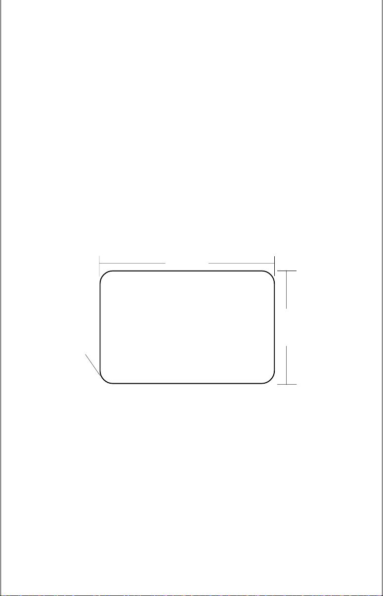
MOUNTING - In-Dash Mount
The mapping unit can be installed in the dash with the supplied hardware
if the dash is 1/2" thick or less. Measure the dash thickness in the area you
need to mount the unit, since dash thickness can vary. If it’s thicker than
1/2", you’ll need the FM-2 in-dash mounting bracket accessory. Make
certain there is clearance behind the dash for the unit and there is enough
room to tighten the bolts on both sides.
7.625"
DASH CUTOUT
.400" radius
(4 places)
5.375"
Once you’ve determined the location for the unit, cut the hole according to
the drawing shown above. Measure carefully before cutting! After cutting
the dash, slide the supplied gasket around the unit and place the unit in the
hole.
Supplied with this unit are rubber pads, bolts, washers, and cam clamps
to attach it to the dash. Peel the adhesive backing off the rubber pads and
place one on each side of the unit in the location where the cam clamp will
touch the back side of the dash. Using the hardware supplied with the unit,
attach the unit to the dash. Looking at the back of the unit, make certain that
the cam clamp on the left side of the unit is pointing down and the cam
3
Page 6
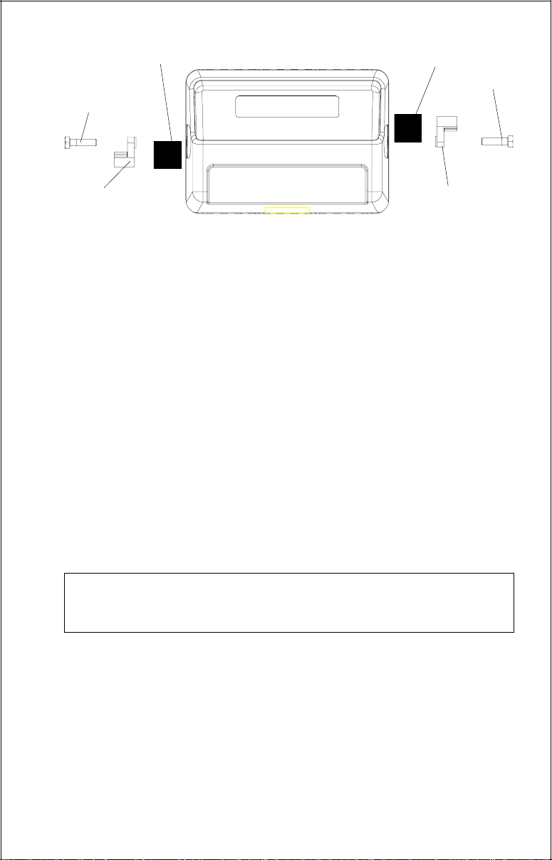
BOLT
RUBBER PAD
RUBBER PAD
BOLT
LOWRANCE
CAM CLAMP
(TURNED DOWN)
CAM CLAMP
(TURNED UP)
clamp on the right side of the unit is pointing up before you start tightening
the bolts.
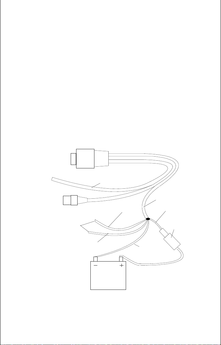
POWER CONNECTIONS
This product works from a twelve-volt battery system. For the best results,
attach the power cable directly to the battery. You can attach the power
cable to an accessory or power buss, however you may have problems
with electrical interference. Therefore, it’s safer to go ahead and attach the
power cable directly to the battery. If the cable is too short, splice 18 gauge
wire onto it. A silver label identifies the power supply portion of the cable.
It has four wires; red, black, green, and white. Red is the positive lead,
black is negative or ground. Make certain to attach the in-line fuse holder
to the red lead as close to the power source as possible. For example, if
you have to extend the power cable to the battery or power buss, attach
one end of the fuse holder directly to the battery or power buss. This will
protect both the unit and the power cable in the event of a short. It requires
a 3-amp fuse.
IMPORTANT!
Do not use this product without a 3-amp fuse wired into the power cable!
Failure to use a 3-amp fuse will void your warranty.
DATA INPUT AND OUTPUT CONNECTIONS
This mapping unit requires navigation data to show position information.
This can come from either a Lowrance GPS module, Lowrance GPS
receiver, or another manufacturer’s navigation receiver that can send the
data in NMEA 0183 version 1.5 or 2.0 format. If you use the Lowrance GPS
module, the NMEA input is not used. If you use any other navigation
receiver for position information, then the NMEA input will have to be used.
It can also accept sonar information from any SAM sonar access module,
which also doesn’t require the NMEA input.
4
Page 7
The wiring connections for the NMEA 0183 version 1.5 are different than
the ones used for the NMEA 0183 version 2.0. If you are using version 1.5,
then use the shielded green and red wires on the mapping unit’s NMEA
cable. If you are using version 2.0, then you’ll be using all four shielded
wires on the NMEA cable.
If you’re using a Lowrance GPS module, simply plug its cable directly into
the in-line connector on the mapping unit’s cable. This sends navigation
data directly to the mapping unit without using any NMEA input. You can,
if desired, use either NMEA output to drive another device while using the
Lowrance GPS module as an input. This mapping unit also has the
provision for a DGPS beacon receiver for use with the Lowrance GPS
module.
TO "P" CONNECTOR
ON GLOBALMAP 2000
TO
NMEA 0180
and 0183
INTERFACE
(FOUR
SHIELDED
WIRES)
NMEA
CABLE
TO
LOWRANCE
GPS MODULE
TO
DGPS
BEACON
RECEIVER
GREEN
WIRE
12 VOLT
BATTERY
WHITE
GlobalMap 2000 POWER CONNECTIONS
5
WIRE
POWER CABLE
RED
WIRE
3 amp
FUSE
BLACK
WIRE
Page 8

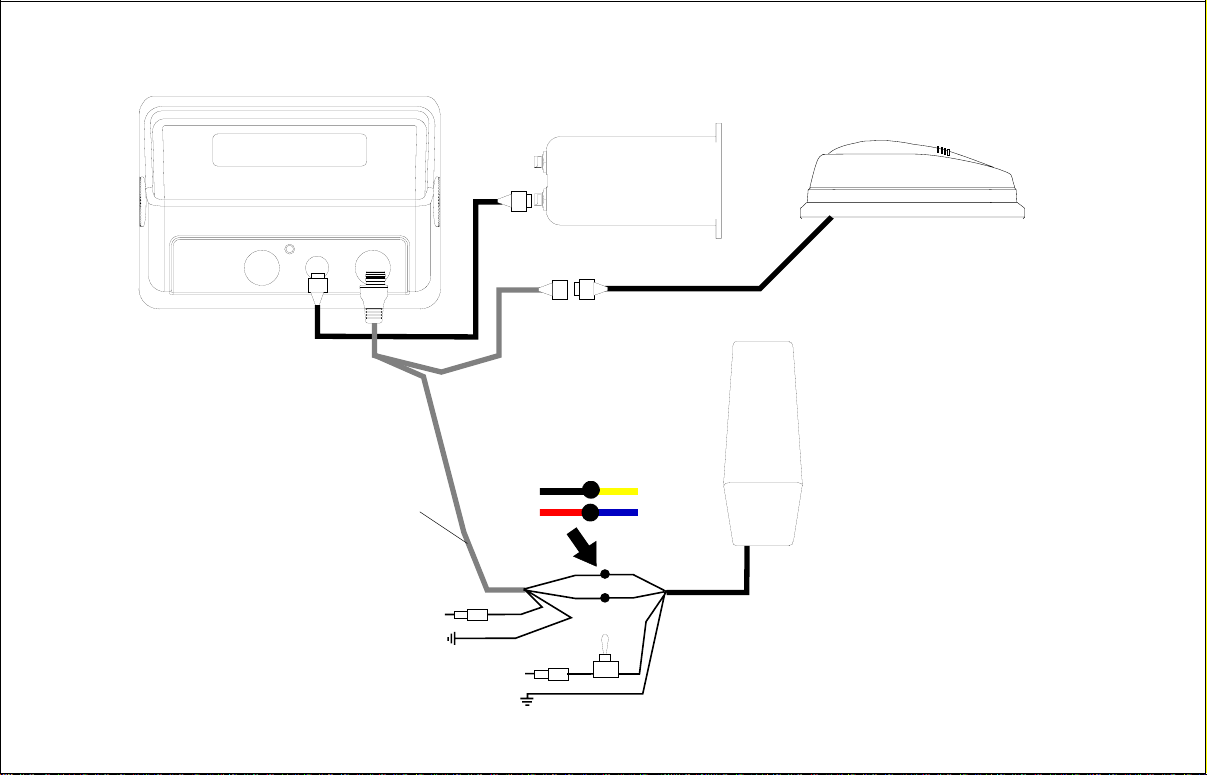
Lowrance Accessory Wiring Diagrams
Since there are many different combinations of accessories that are used
with the GlobalMap 2000, the drawings on the next four pages can help
with the installation. (Note: The black connector on the GlobalMap 2000 is
covered by a black plastic cap. Carefully pry this cap off to gain access to
the connector.)
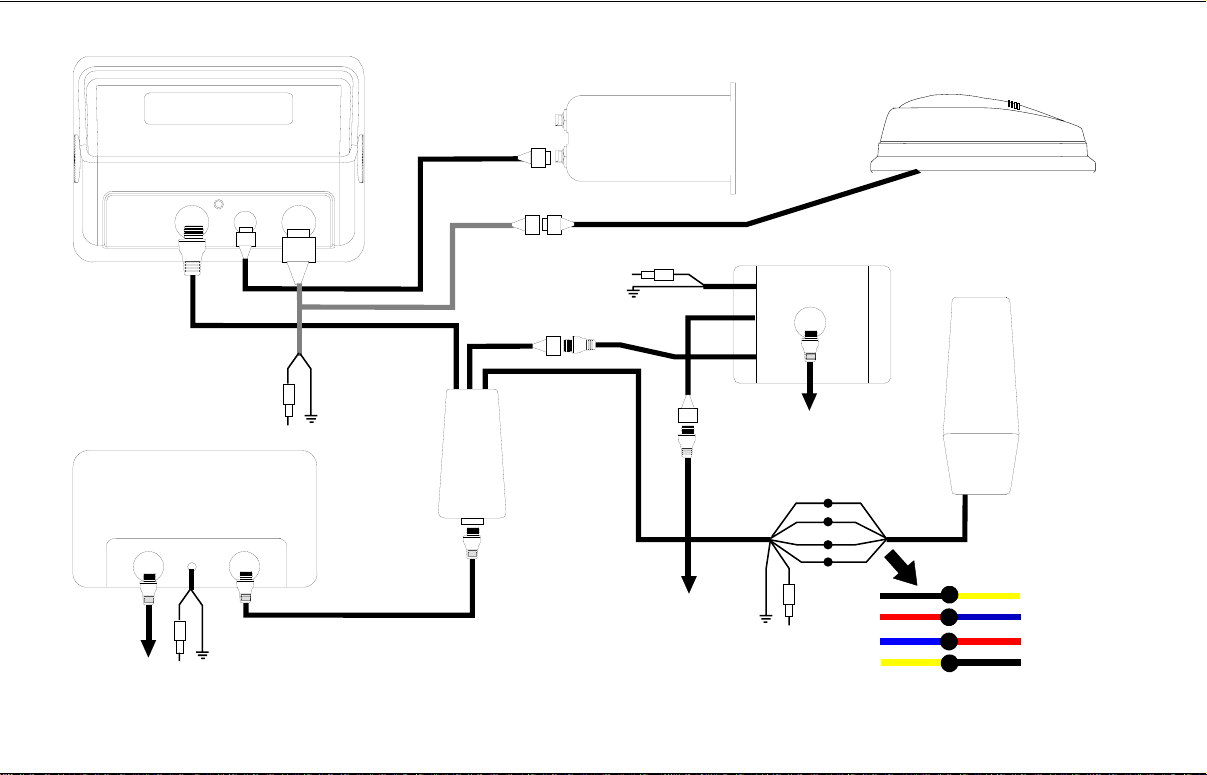
The diagram on page 7 shows the GlobalMap 2000 connected to a
Lowrance GPS receiver and DGPS receiver, and both 192 kHz and 50 kHz
(SAM) sonar modules. In order to use both a DGPS receiver and a SAM
module, (or two SAM modules) you must use the optional DGPS Dual
Frequency Interface. When this adapter is used, power to all Lowrance
accessories is switched through the GlobalMap 2000, so accessory
switches aren’t necessary. Any other manufacturer’s accessory will need
to be connected directly to 12-volt power, through it’s own fuse.
Note: Do not connect the power wires from any beacon receiver other than
a Lowrance DGPS receiver to the DGPS Dual Frequency Interface! All
receivers tested by Lowrance draw more current than the Lowrance
receiver, which will exceed the interface’s current capability. You can
connect any manufacturer’s beacon receiver to the data wires (white and
green) without problem. Also, a SAM-50HPD cannot be connected directly
to a GlobalMap 2000.
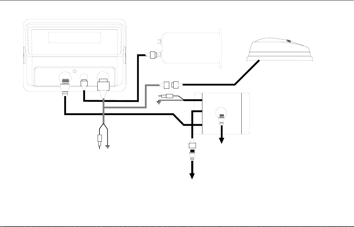
Page 8 shows a GlobalMap 2000 with a Lowrance GPS module, DGPS
receiver, and a MapLink. The diagram on page 9 shows a SAM-ST,
MapLink, and GPS module.
DGPS DUAL FREQUENCY INTERFACE WIRING
TO DGPS DUAL
FREQUENCY
INTERFACE
WHITE (TO DGPS RECEIVE)
GREEN (TO DGPS TRANSMIT)
BLUE (SWITCHED +12 VOLTS)
BROWN (GROUND)
RED (TO +12 VOLTS)
BLACK (GROUND)
6
Page 9
LOWRANCE
MAPLINK
LOWRANCE
GPS MODULE
GLOBALMAP
2000
7
TO 50 KHZ
TRANSDUCER
12 VDC
SAM-50HPD
TO 12 VDC
TO
TO 12 VDC
DGPS DUAL
FREQUENCY
INTERFACE
TO
SPEED/TEMP
SENSOR
SAM-ST
TO 192 KHZ
TRANSDUCER
WHITE
GREEN
TO
12 VDC
BLUE
BROWN
LOWRANCE
DGPS
BEACON
RECEIVER
WHITE
GREEN
RED
BLACK
Page 10
LOWRANCE
GLOBALMAP
2000
MAPLINK
LOWRANCE
GPS MODULE
8
DGPS
BEACON
RECEIVER
POWER CABLE
TO
12 VDC
WHITE
GREEN
RED
BLACK
WHITE
GREEN
RED
BLACK
TO
12 VDC
Page 11
LOWRANCE
MAPLINK
LOWRANCE
GPS MODULE
9
GLOBALMAP
2000
TO
12 VDC
TO 12 VDC
SAM-ST
TO 192 KHZ
TRANSDUCER
TO
SPEED/TEMP
SENSOR
Page 12

NMEA 0183, VERSION 1.5 WIRING CONNECTIONS
The shielded red and green wires are for a NMEA 0183, version 1.5
interface. The GlobalMap 2000 sends data to other electronic navigation
devices through the green wire and receives NMEA data through the red
wire. If the red and green wires are not used, tape their ends so that they
cannot short.
To connect a device to the mapping unit’s NMEA 0183 version 1.5 input
(send data to the GlobalMap 2000), attach a twisted pair cable from the
device’s NMEA output to the red shielded wire on the NMEA cable and the
black wire (ground) on the POWER cable. (See page 12 for wiring
diagrams.)
To connect a device to the NMEA 0183 version 1.5 output (GlobalMap
2000 sends data to another device), attach a twisted pair cable from the
other device’s NMEA 0183 input to the green wire on the NMEA cable and
the black wire on the POWER cable. See the other instrument’s manual for
more wiring instructions.
NMEA VERSION 2.0 WIRING CONNECTION
Use the four shielded red, black, white and green wires on the NMEA cable
for a NMEA 0183, version 2.0 interface. This is a shielded, balanced line
interface. Do not use the shield on these wires! Trim the shield back, away
from the splice when you attach wires from another device to the mapping
unit. The GlobalMap 2000 sends data (transmits) to another electronic
navigation device through the shielded white and green wires and receives
NMEA data through the shielded red and black wires. If the any of these
wires are not used, tape their ends so that they cannot short.
To send version 2.0 data to the GlobalMap 2000, connect the other
device’s NMEA 0183 version 2.0 output to the mapping unit’s NMEA 0183
version 2.0’s input (GlobalMap receives data) by attaching a twisted pair
cable from the other device’s NMEA output to the shielded red and black
wires on the mapping unit’s NMEA cable.
In order for the GlobalMap 2000 to send data to another device, connect
the other device’s NMEA 0183 version 2.0 input to the mapping unit’s
NMEA 0183 version 2.0’s output (GlobalMap sends data) by attaching a
twisted pair cable from the other device’s NMEA input to the shielded white
and green wires on the mapping unit’s NMEA cable.
For the GlobalMap 2000 to both send and receive NMEA 0183, version 2.0
data , see the wiring diagram at the bottom of page 13.
10
Page 13
NMEA 0183, VERSION 1.5 WIRING CONNECTIONS
GLOBALMAP 2000
NMEA CABLE
BLACK WIRE
GLOBALMAP 2000
POWER CABLE
GLOBALMAP 2000
NMEA CABLE
OTHER DEVICE'S NMEA 0183,
VERSION 1.5 OUTPUT CABLE
RED WIRE
12 VOLT
BATTERY
GLOBALMAP 2000 RECEIVING
NMEA 0183 VERSION 1.5 DATA
FROM ANOTHER DEVICE
OTHER DEVICE'S NMEA 0183,
VERSION 1.5 INPUT CABLE
GREEN WIRE
BLACK WIRE
GLOBALMAP 2000
POWER CABLE
12 VOLT
BATTERY
GLOBALMAP 2000 SENDING
NMEA 0183 VERSION 1.5 DATA
TO ANOTHER DEVICE
11
Page 14
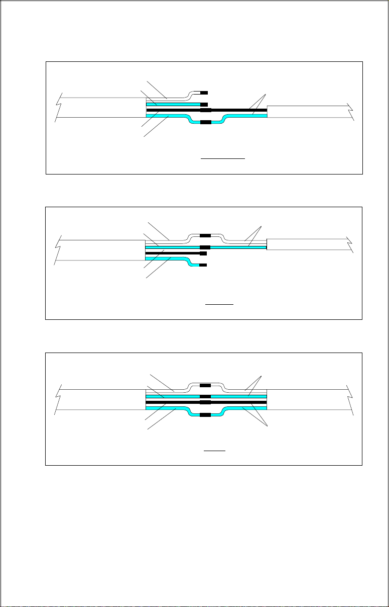
NMEA 0183, VERSION 2.0 WIRING CONNECTIONS
WHITE (+)
GREEN (-)
GLOBALMAP 2000
NMEA CABLE
BLACK (+)
RED (-)
TRANSMIT WIRES
GLOBALMAP 2000 RECEIVE NMEA 0183
VERSION 2.0 ONLY
OTHER DEVICE'S
NMEA OUTPUT
WHITE (+)
GREEN (-)
GLOBALMAP 2000
NMEA CABLE
BLACK (+)
RED (-)
RECEIVE WIRES
OTHER DEVICE'S
NMEA INPUT
GLOBALMAP 2000 SEND NMEA 0183
VERSION 2.0 DATA ONLY
WHITE (+)
GREEN (-)
GLOBALMAP 2000
NMEA CABLE
BLACK (+)
RED (-)
RECEIVE WIRES
OTHER DEVICE
TRANSMIT WIRES
GLOBALMAP 2000 SEND AND RECEIVE NMEA 0183
VERSION 2.0 DATA
Remember, under no circumstances should the shields on the GlobalMap’s
wires be connected to the ground on the other device. See the other
instrument’s manual for more wiring instructions.
NOTE: When using the shielded wires (NMEA 0183 version 2.0), do not
connect the shielded black wire on the NMEA cable to the battery’s ground.
12
Page 15
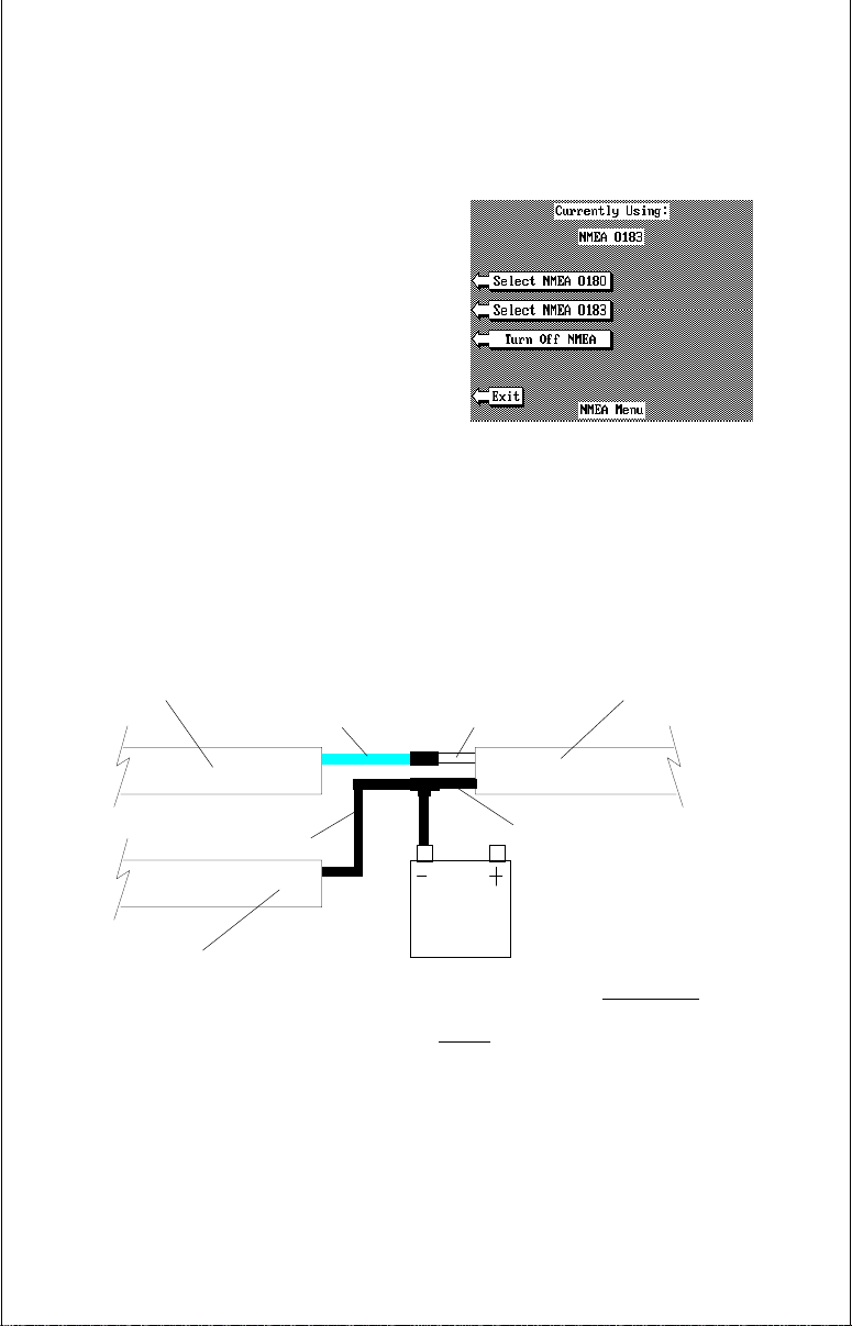
Connecting a LMS-350/350A to the GlobalMap 2000
To connect a Lowrance LMS-350 or LMS-350A with a GPS module to the
GlobalMap 2000, first follow the wiring diagram at the bottom of this page.
After all wiring is completed, plug the two units in and turn them on. On the
LMS-350, then press the GPS key, then
the MENU key. Now press the key next to
the “Change GPS Settings” label. Press
the key next to the “Select NMEA” label.
The screen shown at right appears. Now
press the key next to the “Select NMEA
0183” label. Finally, press the key next to
the “Exit” label. The LMS-350 will send
position information to the GlobalMap
2000 as soon as the GPS module locks
on to the satellites. The GlobalMap 2000
LMS-350 MENU
doesn’t need any setup.
GLOBALMAP 2000
NMEA CABLE
BLACK WIRE
GLOBALMAP 2000
POWER CABLE
RED WIRE
LMS-350
POWER CABLE
WHITE WIRE
BLACK WIRE
12 VOLT
BATTERY
GLOBALMAP 2000 RECEIVING
NMEA 0183 VERSION 1.5 DATA
FROM THE LMS-350
13
Page 16
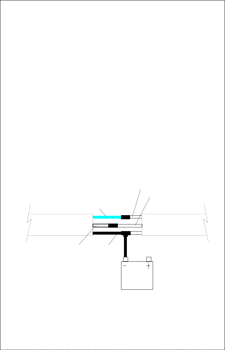
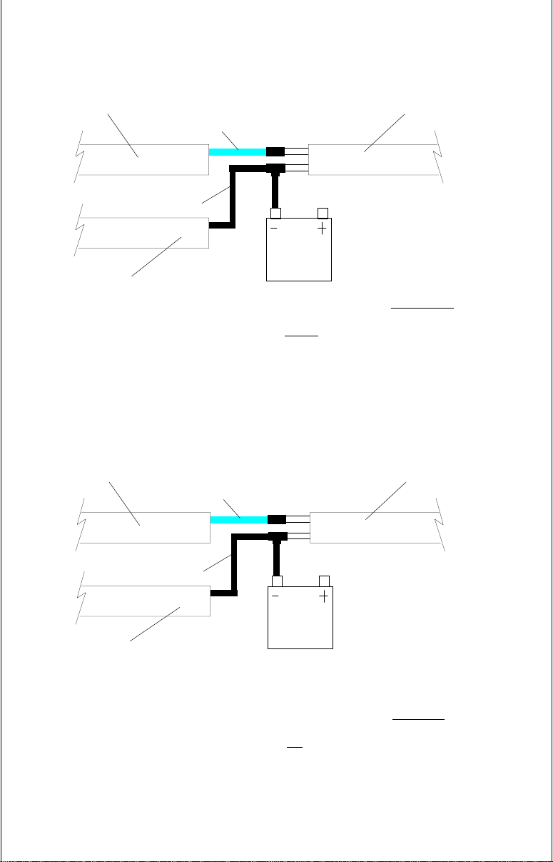
DGPS BEACON RECEIVER CONNECTIONS
If a Lowrance GPS module is connected to the GlobalMap 2000, any brand
of differential (DGPS) beacon receiver can also be connected, giving you
higher accuracy positions in the area covered by the beacon receivers.
The unshielded green and white wires on the POWER cable are used for
the differential (DGPS) beacon receiver. (Note: You can also use the
diagram on pages 7 or 8 if you’re using a Lowrance DGPS receiver.)
To connect the beacon receiver, attach a twisted pair cable from the
beacon receiver’s output to the green and black wires (unshielded) on the
mapping unit’s POWER cable as shown below. Solder the ground
conductor of the twisted pair to the black wire on the power cable. If needed,
also attach a twisted pair cable from the beacon receiver’s input to the
white and black wires on the mapping unit’s POWER cable. (Not all beacon
receivers require an input.)
After the beacon receiver is connected, see the “GPS/DGPS Setup”
section for information on setting the communication parameters for the
DGPS receiver.
DGPS RECEIVER OUTPUT
DGPS RECEIVER INPUT
(IF NEEDED)
GREEN WIRE
GLOBALMAP 2000
POWER CABLE
WHITE WIRE
BLACK
WIRE
12 VOLT
BATTERY
DGPS RECEIVER'S
NMEA 0183 CABLE
GLOBALMAP 2000 DGPS RECEIVER CONNECTIONS
14
Page 17
The LOWRANCE LGC-1 GPS MODULE
9
This GPS receiver is small, rugged, and fast. The five channel design lets
it track all satellites in view and acquire up to five satellites at one time. It
sends position information once every second. By incorporating Rockwell’s
GPS receiver technology with Lowrance’s state-of-the-art design and
manufacturing capabilities, Lowrance brings to the consumer one of the
most advanced line of GPS marine navigation systems available in the
world.
LGC-1 GPS MODULE INSTALLATION
The GPS module can be installed on a flat surface or (with the supplied
adapter) on a pole. Mount the module in an area that guarantees a clear
view of the sky at all times. In order for the module to receive the signals
from the satellites, it must not be obstructed. An ideal location is on a cabin
roof, or deck. The gunnels also make a good location. Attaching the pole
mounting adapter let you install the module on a one inch mast. However,
for lightning protection, the antenna shouldn’t be the highest part of the
boat.
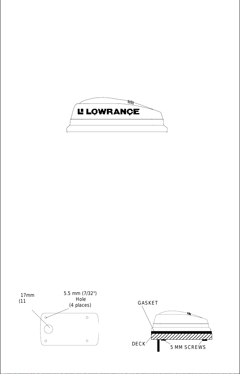
Surface Mounting - With Access
If you have access underneath the mounting surface, use the gasket
supplied with the GPS module as a template. Drill four 5.5 mm (7/32") holes
and one 17 mm (11/16") hole for the module’s cable. Attach the cable to
the module and pass it down through the hole in the gasket and the
mounting surface. Use 5 mm screws, flat washers, and lock washers to
fasten the GPS module to the mounting surface. Route the cable to the
GlobalMap 2000.
17mm
(11/16")
Hole
5.5 mm (7/32")
Hole
(4 places)
15
GASKET
DECK
23456789012345678
5 MM SCREWS
Page 18
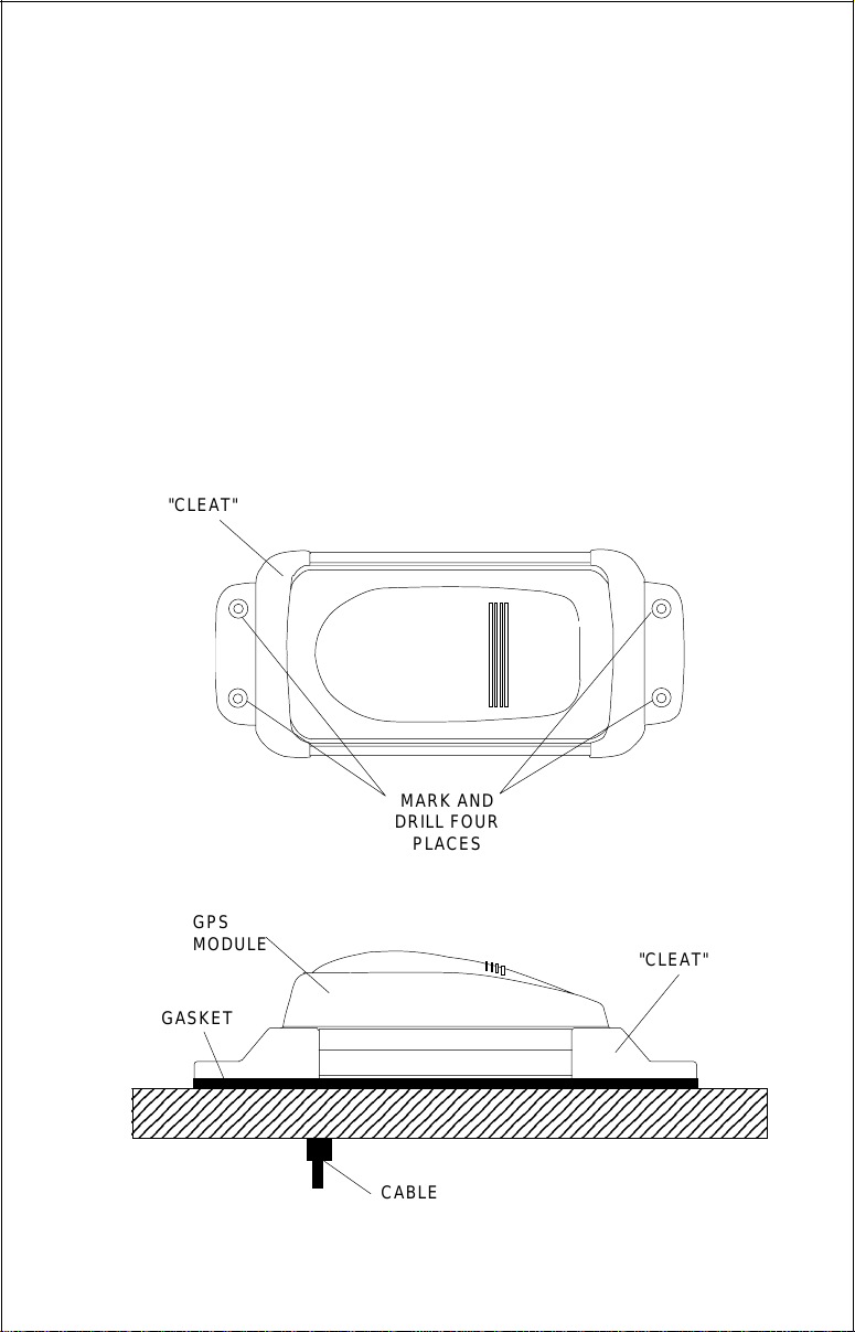
Surface Mounting - Without Access
3
3
3
If you don’t have access to the back side of the mounting surface, use the
“cleats” supplied with the GlobalMap 2000. (Note: This is assuming you
can “snake” the module’s cable to a location that is accessible. A hole will
still need to be drilled in the mounting surface for the cable.) Using the
gasket as a template, mark and drill the 17 mm (11/16") hole for the cable.
Attach the cable to the module and drop the other end of the cable through
the gasket and down the hole. Place the module on the gasket. Slide the
“cleats” onto each end of the module and (using the cleats as templates)
mark four holes for 5 mm (#10) mounting screws. Drill the holes, then
replace the cleats on the module and fasten them to the mounting surface
with 5 mm (#10) screws. Route the cable to the GlobalMap 2000.
"CLEAT"
MARK AND
DRILL FOUR
PLACES
GPS
MODULE
"CLEAT"
GASKET
23456789012345678901234567890121234567890123456789012
23456789012345678901234567890121234567890123456789012
23456789012345678901234567890121234567890123456789012
CABLE
16
Page 19
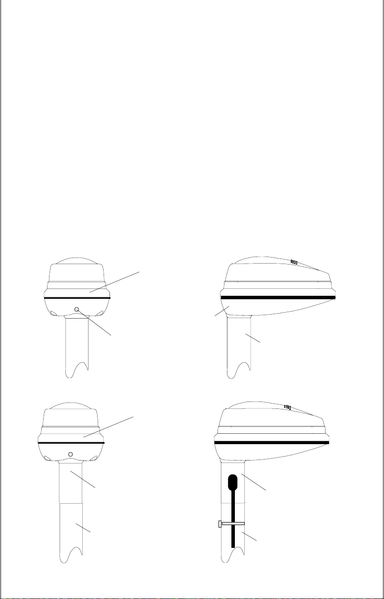
Pole Mount
First, thread the pole mounting adapter onto the mounting pole or ratchet
base. Align the pole mounting adapter so the module will face the bow of
the boat. Install and tighten the set screw into the pole mounting adapter
and tighten it securely. This should prevent the GPS module from
unscrewing from the pole. Place the gasket onto the pole mounting
adapter. Now attach the cable to the GPS module and pass the cable
through the gasket, pole mounting adapter, and pole. Set the GPS module
on top of the pole mounting adapter and align the four threaded holes in the
module with the holes in the pole mounting adapter. Using the four
stainless steel 5 mm screws and lock washers supplied with the LGC-1,
attach the pole mounting adapter to the GPS module. This completes the
assembly. If the pole or mast you’re using isn’t hollow or if the hole in the
middle of the pole is too small for the connectors, use the cable mounting
adapter supplied with your unit. Thread the cable mounting adapter into the
GPS pole mounting adapter. Then thread the pole into the cable mounting
adapter. Route the cable down the outside of the pole.
GPS
MODULE
POLE
MOUNTING
SET
SCREW
ADAPTER
POLE
CABLE
MOUNTING
ADAPTER
POLE
GPS
MODULE
CABLE
MOUNTING
ADAPTER
POLE
17
Page 20

SAM SONAR ACCESS MODULE
In order for the GlobalMap 2000 to show sonar data, a sonar access
module (SAM) and transducer must be installed. Follow the installation
instructions included with the sonar access module. Route the cable from
the sonar module to the black connector on the GlobalMap 2000. (Note:
The black sonar connector on the GlobalMap 2000 is covered by a black
plastic cap. Carefully pry this cap off to gain access to the connector.)
Follow the installation instructions included with the transducer and mount
it on the boat. Route its cable to the sonar module and plug it into the black
connector. The sonar module is now ready for use.
LOWRANCE INLAND MAPPING SYSTEM
Until recently, people using inland lakes and rivers were left out of the
electronic mapping market. Lowrance has addressed this market with our
“IMS SmartMap™” series of mapping cartridges that use the MapLink™
to connect to the GlobalMap 2000. All of the contiguous 48 states are
covered by these cartridges, allowing exceptional detail of lakes and rivers.
Also, cities, towns, highways, and roads are shown on these maps. To
order these cartridges, contact your local dealer or LEI Extras at 1-800324-0045 (USA only).
MAPLINK™
The GlobalMap 2000 has an internal “background” map that covers almost
the whole world. It shows southern Canada, all of the continental United
States, and Mexico at a higher resolution than other countries. This map
is sufficient for most users, however, Lowrance has an optional cartridge
reader called the Maplink™ that accepts IMS SmartMap™ and C-MAP
cartridges. The SmartMap™ cartridges were created by Lowrance and
have highly detailed maps of the continental United States. The C-MAP
cartridges have small coastal area maps built into them that allows you to
“zoom” in and see much more detail than is available on the built-in map.
The Maplink also has the C-MAP background map built into it, so you have
the option of using it or the Lowrance background map at any time, even
if a C-MAP cartridge isn’t plugged into the Maplink.
To install the Maplink, follow the instructions included with it. It can be
mounted on top of the dash, under the dash, or in the dash for a clean,
professional look. Once it’s installed, route the cable included with the
Maplink to the small connector on the back of the GlobalMap 2000. If the
supplied cable is too short, an extension cable, model MLXT-12 is
available that is 12 feet long. After connecting the cable, the Maplink is
ready for use. The Maplink receives its power through the connecting
cable, simplifying the installation.
18
Page 21
Notice!
You can attach up to seven Maplinks to the GlobalMap 2000. This lets
you use different maps without having to unplug one and replace it with
another when you move out of the first map’s area. This also allows the
mounting of the Maplinks under the dash, out of sight.
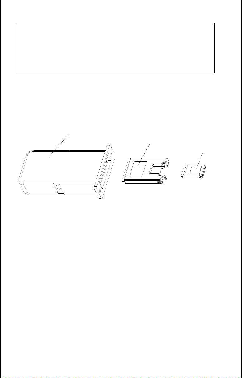
The Maplink accepts the large C-Map cartridges without adapters. Lowrance IMS SmartMap cartridges and Lowrance supplied C-Map cartridges
require an adapter that comes with the Maplink as shown below.
MAPLINK
CARTRIDGE
ADAPTER
SMARTMAP
CARTRIDGE
If you’re not using the Maplink or Lowrance Inland Mapping Modules,
connect the small gray terminator plug supplied with the GlobalMap 2000
into the small connector on the back of the unit. This will protect the
connector on the back of the unit from the elements.
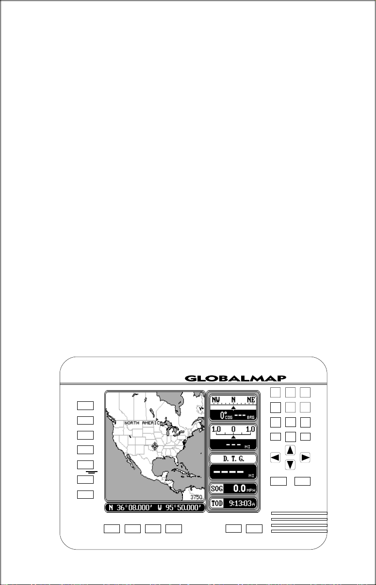
KEYBOARD
The keyboard has keys arranged in a vertical column on the left, plus a
horizontal row at the bottom. A ten-key pad and arrow keys on the right side
of the screen let you enter and change data on the screen. The menu key
in the bottom left corner of the keyboard activates the first menu page. The
keys along the bottom of the screen are used to switch between maps and
the digital navigation, steering, and position screens. The Event Marker
key lets you place icons on the display, while the Man Overboard key is
used for emergencies.
MAP - Press this key to show the Mapping Screen.
NAV - This key shows the digital navigation screen.
19
Page 22
STEER - Press this key to show the Steering Screen.
SONAR - This key switches the unit to the sonar displays.
ZOOM IN - Expand the map to see more detail by pressing this key.
ZOOM OUT - To see a wider area of the map, press this key.
CENTER - Centers the map around your present position.
CURSOR - Pressing this key activates the moveable cursor lines.
WAYPT/ROUTE - This key lets you save or recall a waypoint or route.
WAYPOINT QUICK SAVE - Pressing this key instantly saves your
position.
EVENT MARKER - To mark a location on the plotter screen, use this key.
MAN OVERBOARD - Pressing this key instantly saves your present
position and switches the unit into a mode that shows navigation data to
the last saved position.
ARROW KEYS - These keys are used to make menu selections and to
move the cursor lines on the screen.
LOWRANCE
ZOOM IN
ZOOM OUT
CENTER
CURSOR
WAYPT/ROUTE
WAYPT
MENU
MAP NAV STEER SONAR
20
20002000
2000
20002000
123
456
789
0
OVERBOARD
ENT
MAN
CLR
EVENT
MARKER
ON
OFF
LIGHT
Page 23
CLR - This key clears menus and erases entries from the screen.
ENT - This key is used to enter numbers and make selections.
ON - The ON key turns the GlobalMap 2000 on. Pressing this key after
turning the unit on also turns the display and keyboard’s lights on.
OFF - Press and HOLD the OFF key to turn the mapping unit off.
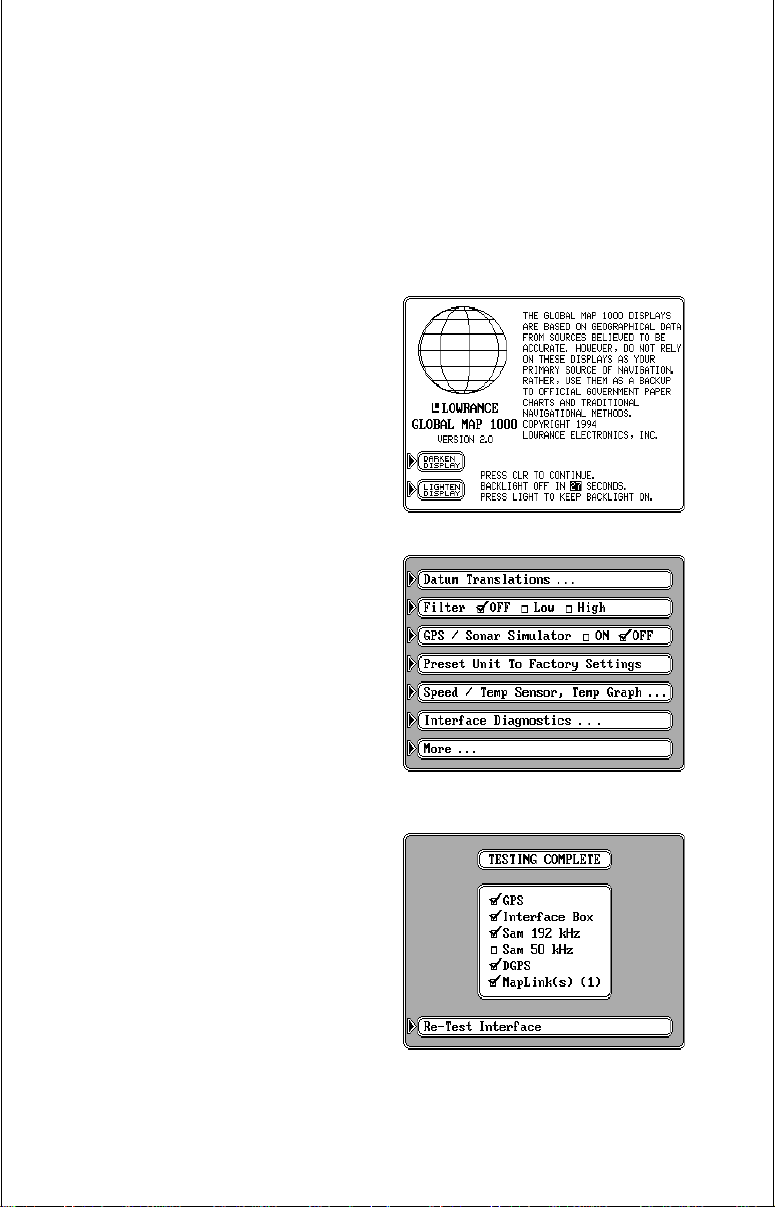
Interface Test
You can test the mapping unit and it’s
accessories after they’re installed to
make certain all of the cables are connected properly.
To do this, make certain all of the accessories are connected to the mapping
unit. Then press the ON key. The screen
at right appears. Press the CLR key to
erase this screen. Now press the MENU
key three times. Each time you press
the MENU key, a new list of menu items
appear on the screen. You should be
viewing the screen shown at right. Press
the key next to the “Interface Diagnostics” label. The screen shown below
appears.
A list of the possible Lowrance accessories is on this screen. A check mark
appears next to the item if it is communicating with the mapping unit. To run
this test again, press the key next to the
“Re-Test Interface” label at the bottom
of the screen.
Press the CLR key to erase this screen.
21
Page 24

GETTING STARTED - INITIALIZATION AND I/O
Once all power and data connections have been made, the next step is to
turn the GlobalMap 2000 on. A message appears on the screen. Press the
CLR key to erase this message. If a Lowrance GPS module is connected,
then the mapping unit sends a “cold-start” message to the module. The
module will then start looking for the satellites. It can take up several
minutes for the module to determine your position. To speed up this
process, you can initialize the module by sending it your present position,
time, altitude, and date. See below for details on initializing the GPS
module.
If you have another manufacturers GPS or Loran-C receiver connected to
the GlobalMap 2000 through the NMEA cable, the mapping unit will show
the present position as soon as the receiver sends it. If you’re certain the
navigation receiver is sending position data, but the present position
display continues to flash for over 15 seconds, (signifying that it isn’t
receiving data) then check all wiring connections.
SAM modules start working at the same time the mapping unit is turned on.
The mapping unit also automatically sends both versions of NMEA 0183
data at power-on.
Initialization - GPS Module
Note: Read this section only if you have a GPS module connected to the
GlobalMap 2000. If you are using the NMEA 0183 input for position
information, skip this part.
In order for the GPS module to send position information, it must first find
the satellites. If you simply turn the unit on and wait, the unit will find them
by itself in 15 minutes or less. This is called “Cold Start.” If you let it find the
satellites, the time display will probably be wrong, since it will be showing
UTC time or the time at Greenwich, England. However, all other navigation
displays, including the position display will be correct. (You can set the time
to your local time.) To speed up the satellite acquisition process, you can
initialize the GPS module or “tell it where it is” the first time it’s turned on.
This initialization process is usually done only once and requires the
following data:
1. Your present position in latitude/longitude.
2. Your elevation above sea level (altitude).
3. Today’s date and time.
22
Page 25
The unit usually only takes a few minutes or less to find the satellites once
it’s been initialized by the user.
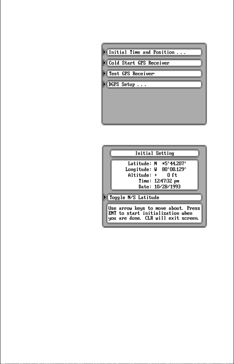
To initialize the GPS module,
first press the MENU key. Now
press the key next to the “GPS
/ DGPS Setup” label. The screen
at right appears. Finally, press
the key next to the “Initial Time
and Position” label. The screen
shown below appears.
This is the GPS module initialization screen. The settings now
in use are shown at the top of
the display. The first number in
the latitude display should be
flashing. If you’re using the unit
for the first time, these settings
are probably wrong for your position and time. To change any
of the numbers on this display,
simply press the arrow keys to
move to the desired number
that you wish to change. For
example, to change the latitude
to 41°18.023', first press the 4
key while the “3” in the latitude is
flashing. This changes the “3” to
a “4”. It also moves one digit to
the right, making the number “5” start flashing. Now press the 1 key.
Continue until all of the numbers in the latitude have changed. If you need
to change the latitude from north to south, press the key next to the “Toggle
N/S latitude” label in the middle of the screen. When you’re finished with
the latitude, press the down arrow key once. This moves you to the
longitude field. An asterisk (*) flashes in front of the “8” in the longitude. If
your longitude is less than 100 degrees, simply press the right arrow key
to move to the “9”, then enter your present longitude the same way you
entered the latitude. If your longitude is over 100 degrees, simply enter your
present longitude. The label at the middle of the screen now shows “ Toggle
E/W Longitude”. Press the key next to this label to change the longitude
from west to east, if necessary.
23
Page 26
Continue entering your altitude, present time and date the same way you
entered your present position. If you make a mistake entering a number,
use the arrow keys to move back to the number that you wish to change,
then enter the correct number.
When all of the numbers on the screen are correct, press the “ENT” key.
This sends the values you entered to the GPS module which should
shorten the time required for it to find the satellites and return your present
position. If you don’t move a long distance (over 100 miles) with the unit
turned off, then you probably won’t need to do the initialization again, since
it stores all of the last known position settings in memory each time it’s
turned off. An internal clock keeps track of the time, even when the unit is
turned off, so that it will be correct the next time it’s used.
Once the GPS module finds the satellites and displays the correct latitude/
longitude for your position, then the GlobalMap 2000 is ready for use.
COLD START
When the GlobalMap 2000 is turned on for the first time “out of the box”,
it automatically sends a “cold start” message to the Lowrance GPS
module. You can also send a cold start message to the receiver. If the unit
can’t lock on to the satellites using the data you’ve given it, or if it has trouble
finding the satellites, perhaps it is using the wrong data. This can happen
if you’ve entered the wrong data by accident. For example, given it east
longitude instead of west. Or if you’ve moved a long distance with the unit
turned off.
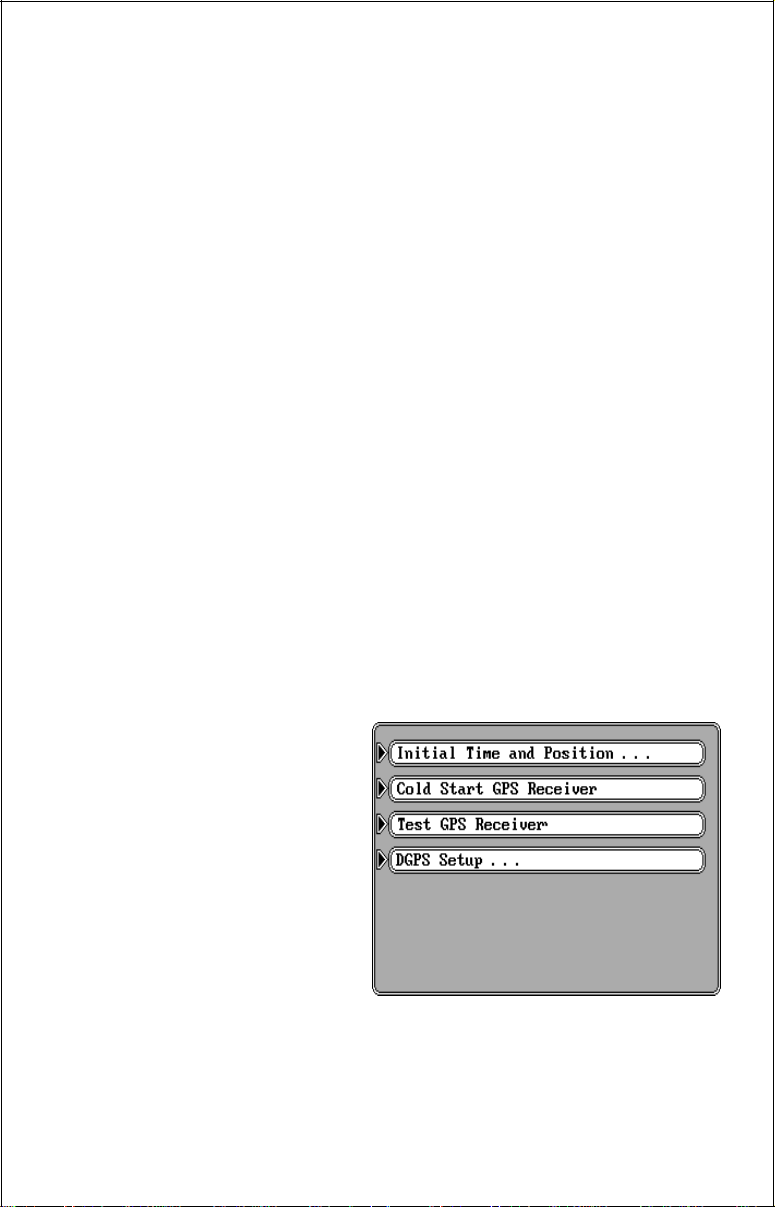
To send a cold start message to
the receiver, first press the
MENU key. Now press the key
next to the “GPS/DGPS Setup”
label. The screen at right appears. Finally, press the key
next to the “Cold Start GPS
Receiver” label. The unit will
begin a cold start technique to
find the available satellites. It
should lock on to them in less
than 15 minutes. Remember,
when it does, your local time
and possibly date display will probably be wrong. Use the method shown
above to set the time and date. Once this is done, an internal clock will keep
the correct time, even when the unit is turned off. The GPS system updates
this clock when the unit is locked on to the satellites.
24
Page 27
GPS RECEIVER TEST
If you have a GPS module connected to the GlobalMap 2000, a test can
be performed on the receiver inside the module. This tests many parameters of the receiver, letting you know if there is a malfunction. If the GPS
module fails any of the tests on the shown on the screen, then contact the
Lowrance Factory Customer Service Department.
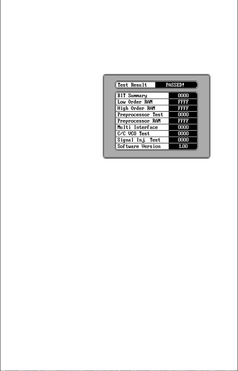
To activate the receiver test,
first press the MENU key, then
press the key next to the “GPS/
DGPS Setup” label. Now press
the key next to the “Test GPS
Receiver” label. The screen
shown at right appears. “Testing” appears in the box at the
top of the screen while the test
is in progress. This will take
several seconds. When the test
is over, “PASSED” appears at
the top of the screen if the module passed the test and “FAILED” if there’s a problem. The boxes on the
screen show the results of each test. These results are coded and will show
either “FFFF” or “0000”. The version of the software used in the GPS
module appears at the bottom of the screen.
To exit this screen, press the CLR key.
DGPS SETUP
Some areas have installed or are planning to install differential transmitters
that send correction data to a special receiver. The U.S. Coast Guard has
installed many differential transmitters along coastal waters, navigable
rivers, and the Great Lakes. When a DGPS receiver is connected to the
GlobalMap 2000 along with a Lowrance GPS module, highly accurate
positions can be plotted. If you have a differential (DGPS) beacon receiver
connected, you’ll need to make some settings on the GlobalMap 2000. To
do this, first press the MENU key, then press the key next to the “GPS/
DGPS Setup” menu. Now press the key next to the “DGPS Setup” label.
The screen shown at the top of the next page appears. Turn the DGPS
input on by pressing the key next to the “DGPS” label. Next, select the type
of DGPS receiver that’s connected to the mapping unit by pressing the key
next to the “DGPS Type: label. A list of DGPS receivers appears. Select
your receiver by pressing the key adjacent to it’s label. See your DGPS
receiver’s owner’s manual if your receiver isn’t listed. You may be able to
use one of the receivers on the list or use RTCM104.
25
Page 28
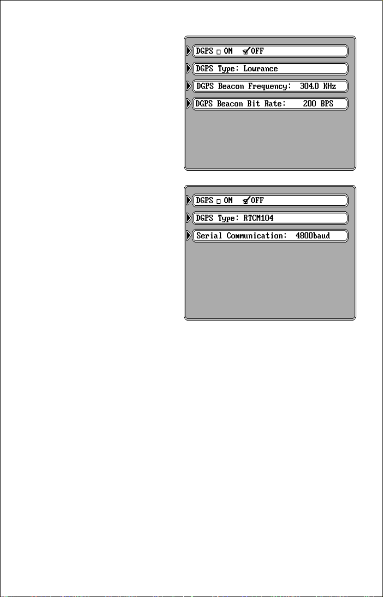
RTCM 104
The GlobalMap 2000 can “talk”
to the beacon receiver using
RTCM104, a standard communications language. With this
protocol, all you need to do is
set the baud rate to the same as
the one used by your beacon
receiver. The unit’s default is
4800 baud. If your unit uses a
different baud rate, press the
key next to the “Serial Communication” label. A new screen
appears with different baud rate
labels. Press the key next to the
desired label, then press the
CLR key. If the beacon receiver
is connected and turned on, differential correction data should
now be received by the mapping unit. Press the CLR key to
exit this screen.
Lowrance, Starlink, and
Magnavox Beacon Receivers
The Lowrance, Starlink and Magnavox beacon receivers must have the
frequency and bit rates set.
Most DGPS transmitters have different frequencies and bit rates. The
GlobalMap 2000 needs to know the frequency of the transmitter and its bit
rate that you will be using with the Lowrance, Starlink, or Magnavox beacon
receivers. To enter the DGPS transmitter’s frequency, first select the
desired receiver. Now press the key next to the DGPS Beacon Frequency
label. Using the numbered keys, enter the frequency of the transmitter.
Press the ENT key when you’re finished. Next, press the key next to the
“DGPS Beacon Bit Rate:” label. Enter the bit rate, again using the
numbered keys. Press the ENT key when you’re finished. If you have a
Starlink beacon receiver, you may not have to enter the frequency or the
bit rate. Simply press the key next to the “Automatic Mode” label and the
Starlink receiver will tell the GlobalMap 2000 the transmitter frequency and
bit rate, automatically.
When you’re finished with this screen, press the CLR key. The GlobalMap
26
Page 29

should start using the data from the differential beacon receiver. See the
“DGPS Beacon Receiver Status” section for more information.
GPS/DGPS INFORMATION SCREENS
Note: These screens will have only partial or no data if the GlobalMap 2000
is receiving its data from another navigation receiver through the NMEA
0183 input. You must have a Lowrance GPS module connected to the
mapping unit in order to fully use the satellite information screen.
This screen shows technical data about each satellite in view. This
includes data from the GPS model which shows the location of each
satellite in the sky, it’s identification number and more. To see this display,
press the MENU key, then press the key adjacent to the “ Status Screen”
label. The screen shown below appears.
The GPS receiver’s status
shows in the upper left corner
of the screen. This tells you if
the unit is in the 2D mode (position only), 3D mode (position
and altitude), or if DGPS is
operational. Your present position, altitude, time, and date
show beneath the status.
Beneath the date display is the
fix status. The fix quality has a
range from 0-9. 9 is the best, 0
the worst. As the fix number decreases, the position’s “jitter” increases.
Jitter is the small position changes your present position symbol makes
when you’re not moving. This movement is normal and happens in all
electronic navigation equipment.
The satellites that are in view of the receiver show at the bottom of the
screen. The Lowrance GPS module will track all of the satellites in view.
Using a multiple channel GPS receiver, it will use up to four satellites to
calculate position. The other channels track the remaining satellites. Every
satellite in the constellation has a number assigned to it, called the PRN.
The PRN is the first row. TRK stands for “track.” If the GPS module is
tracking the satellite, then a “T” is placed in this column. If it’s searching for
the satellite, then a “S” appears. ELV is the elevation (height) of the satellite
above the horizon from your position. AZM is the azimuth or direction of the
satellite from your position. For example, if the azimuth of a satellite is 180
degrees, then it is due south. SNR is the signal-to-noise ratio. This tells you
27
Page 30

how strong the satellite’s signal is. The higher the SNR number, the better.
To exit this screen, press the MAP, NAV, STEER, or SONAR keys.
DGPS BEACON RECEIVER STATUS
With both a Lowrance GPS module and a DGPS beacon receiver connected to the GlobalMap 2000, then DGPS receiver status shows on the
status screen. Again, to view this screen, press the MENU key, the press
the key next to the “Status label. A screen similar to the one below appears.
The status of the DGPS receiver shows at the screen’s
top right side. If the mapping
unit is receiving good data from
the DGPS receiver, the word
“Operational” appears at the
top of this screen. Next are
shown the station identification (ID), station frequency
(Freq), station data transmission rate (Rate), signal-to-noise
ratio (SNR), signal strength
(Sig), and age status (AGE).
At the very bottom of the screen are the DGPS statistics (DGPS). An “OK”
in this field means that the DGPS corrections for that satellite are good. A
blank in this field means that there is no corrections for that satellite.
To exit this screen, press the MAP, NAV, STEER, or SONAR keys.
MAP OPERATION
MAPPING/NAVIGATION/STEERING/SONAR DISPLAYS
This mapping unit has mapping, navigation, steering indicator, satellite
information and sonar screens. These displays were designed to show the
most important data. However, you can change all of them (except the
satellite information) to some extent through the “Customize Display”
feature on the second GPS menu screen. To change these screens, see
the “Customize” section in this manual.
Each of the following screens is available by pressing a key at the bottom
of the unit. A detailed description of each screen follows.
28
Page 31

IMPORTANT!
If the data shown in digital numbers on any screen on this unit is flashing,
then it means that data is invalid. Do not rely on data that is flashing! For
example, if the present position display is flashing, then the unit has lost
the position data from the GPS module or NMEA 0183 data input. The
position that is flashing is the last known position, not your present
position! Do not navigate with this unit until you have found the reason
the unit has lost the position data!
MAP SCREEN
The Map screen automatically appears the first time the GlobalMap 2000
is turned on and after a preset. You can also view this screen at any time
by pressing the MAP key. A
screen similar to the one at right
appears. Your present position
appears as a circle with a cross
on the screen. The latitude/longitude of your present position
shows at the bottom of the
screen. Each time you switch to
this screen, it centers your
present position and the map
on the display. To zoom in for a
closer look, press the ZOOM IN
key in the upper left corner. To
zoom out and see a wider area around your present position, press the
ZOOM OUT key. The range, or approximate distance from one side of the
screen to the other is shown in the lower right corner of the map. Each time
you press the ZOOM IN or ZOOM OUT key, the range changes, typically
showing you more detail when you’re zoomed in or a wider area when
you’ve zoomed out.
As you travel, the circle showing your present position moves
on the screen, too. The line
extending from the circle shows
the path you’ve taken.
Pressing the MAP key once
while the map is displayed
causes the whole display to be
used by the map as shown at
right. The digital boxes disap-
29
Page 32

pear. Press the MAP key again
to view a “split-screen” map
and sonar display as shown
below. Pressing the MAP key
again returns the unit to the
original mapping display.
Boxes on the right side of the
screen shown at the bottom of
this page show your course over
ground (COG), or direction
you’re heading, boat speed
(SOG), present time (TOD or
Time Of Day), and navigation
information if you recall a waypoint. (The screen at right shows
navigation data to a recalled
waypoint.) All of the boxes on
the right side of the screen can
be replaced with others. In this
manner you can customize the
screen to your needs. See the
Customization section for a detailed description of the boxes
not shown on this screen.
The box in the upper right corner of the screen is a combination navigation
display. A compass shows your current
course over ground at the top of the box.
This is the direction you’re travelling.
Your course over ground (COG) is also
shown in digital numbers in the bottom
left corner of this box. The course over
ground in this example is 210 degrees.
When a waypoint is recalled (see the waypoint navigation section), the
direction to the waypoint, or bearing, is shown in the bottom right corner of
this box (BRG).
The arrow that points up always shows in the middle of this box. This arrow
points to the bearing of the recalled waypoint on the compass. In this
example, the bearing is 197 degrees. If you steer the boat so that the arrow
that points up is always in line with your course over ground, then you’ll
always steer the shortest, most direct route to the waypoint.
30
Page 33

If you move to the left or right of the optimum course to the waypoint,
another arrow appears on the display with the letters “WYPT”. This arrow
points in the direction you should steer the boat to get back on course. In
the example shown above, you need to steer the boat to the left to get back
on course.
The box shown beneath the compass
box is a course deviation indicator, or
C.D.I. This box has a pointer that moves
to the left or right, depending if you are
left or right of the optimum course line.
The pointer represents the course line.
For example, if you are one-half of a mile
to the left of the desired course, the
pointer will move to the right, and an arrow pointing to the right appears with
the word “STEER” next to it. This means you need to steer to the right to
get back on the correct course. The distance from your present position to
the course line appears at the bottom of this box. This is called “cross track
error”. In this example, the cross track error is 0.05 miles.
Beneath the C.D.I. indicator are the distance to go (DTG), speed over
ground (SOG), and time of day (TOD) boxes.
CENTER MAP
To center the map around your present position (or the cursor), placing it
in the middle of the screen, simply press the CENTER key.
C-MAP DATA OPTION
Buoys and other navigational aids have additional information available
when using a C-MAP cartridge. To view this data, move the cursor on top
of the desired symbol, as shown below left. Now press the ENT key. The
screen shown below right appears. An information box shows on the
screen, giving information about the selected symbol. To erase this
message box, press the CLR key.
31
Page 34

MAPPING OPTIONS
The map screen has a number of choices available that let you optimize
this screen for your own particular boating or navigation situations. To
change the mapping display, first press the MENU key, then press the key
next to the “Mapping Setup...” label. The screen shown below appears.
North Up - Course Up - Center
This mapping unit can display the map in the conventional “north-up”
presentation when it’s first turned on or after a preset. This means north is
always at the top of the screen. If you’re using the Lowrance background
map built into the GlobalMap 2000 or a Lowrance IMS SmartMap™
cartridge, you can change to
the “course-up” orientation. In
this mode, the map rotates as
you change directions. It always keeps your trail moving
straight towards the top of the
screen, no matter what your
actual heading is. The “Center”
mode keeps your present position at the center of the screen
and moves the map around it.
Note: The GlobalMap 2000 won’t operate in the course up or center modes
when the C-MAP background map is in use.
For example, in the traditional
“north-up” mode as shown at
right, no matter which way you
turn, north is always at the top
of the display. If you’re travelling due south, a turn to the left
(east) will look like a turn to the
right on the display. However,
with a “north-up” display as
shown at the top of the next
page, your course line is always straight up, and the map
rotates around your present position. Although this may look confusing at
first, it actually makes reading the map easier. For example, no matter
which direction you’re travelling, features on the map should match your
view outside: an inlet on your left will be shown on the left on the map, an
island on your right will show on the right on the map, etc.
32
Page 35

The “Center” mode (shown below right) keeps your present
position in the center of the mapping display. The map is always
in the “north-up” mode and
scrolls around your present position as you travel. This mode
is similar to the north-up mode,
it just moves the map instead of
your present position. Using this
method always makes it easy
to find your position on the map.
To change from the north-up to
the course-up or center modes,
simply press the MENU key,
then press the key next to the
“Mapping Setup...” label. Now
press the key next to the “North
Up Course Up Center” label
until the check mark is on the
desired box. Press the CLR
key to return to the map screen.
To switch back to the north-up
view, simply repeat the above
steps.
Map Names
Major cities, highways, rivers, lakes, states, and more are shown on the
Lowrance background map and Lowrance cartridges. (C-MAP cartridges
and background map also show the names of many of these landmarks,
but can’t be turned off.) When the mapping unit is first turned on or after it’s
preset, these names are shown on the map. To turn the names off, press
the MENU key, then press the key next to the “Mapping Setup...” label. Now
press the key next to the “Map Names” label. This moves the check mark
from the “ON” to the “OFF” box. Press the CLR key to return to the map
screen.
Area Fill
This unit can fill land masses or water with a gray background. Water is
filled with gray when the unit is first turned on or after a preset. To fill the
land with gray and leave the water white, press the MENU key, then press
the key next to the “Mapping Setup” label. Now press the key next to the
33
Page 36

“Area Fill” label to move the check mark from “Water” to “Land”. Now press
the CLR key. The unit returns to the map screen with the land filled with
gray.
Cartridge Switch
The mapping unit can use either Lowrance IMS or C-MAP™ cartridges. If
you wish to use the C-MAP cartridge, you’ll need to purchase the Lowrance
Maplink cartridge reader. The mapping unit has a Lowrance map of the
world built into it. This is called the “background” map. C-MAP uses their
own background map which is built into the Maplink cartridge reader.
Information from a C-MAP cartridge can’t be displayed while the Lowrance
background map is showing and vice-versa. You must use the C-MAP
background with a C-MAP cartridge and the Lowrance background map
with the Lowrance inland modules. The default setting is the Lowrance
background map and modules.
To switch between the Lowrance and C-MAP maps, press
the MENU key, then press the
key next to the “Mapping
Setup...” label. Now press the
key next to the “Cartridge OFF
Lowrance C-MAP” label. A
message appears: “Press the
ENT key to proceed or press
the CLR key to quit”. If you
pressed the ENT key, the CMAP background map should
now be displayed. If you have a
LOWRANCE BACKGROUND MAP
C-MAP cartridge plugged into
the Maplink, a box will appear
on the map in the area covered
by the cartridge. This area lets
you “zoom-in” much closer than
the standard background map,
typically allowing much more
detail to be shown.
(Note: It is normal for zooming
in or out with C-MAP to be
much slower than with the Lowrance maps.)
C-MAP™ BACKGROUND MAP
34
Page 37

To switch back to the Lowrance map, repeat the previous steps. Switching
to the “Off” box in this menu switches all maps off, turning the display into
a plotter-only mode.
C-MAP Setup
There are several options available to you if you’re using the CMAP system. C-MAP gives you
the capability to turn off or on
the map boundaries, navigation aids, coastal features, restricted areas, and depth lines.
To change any of these features, press the MENU key,
then press the key next to the
“Mapping Setup...” label. Now
press the key next to the “CMAP Setup...” label. The screen
shown at right appears. Simply press the key next to the label of the feature
you wish to change. When you’re finished, press the CLR key to return to
the map screen or press the key next to the “More” label to return to the
mapping setup menu.
CURSOR
The GlobalMap 2000 has moveable cursor lines that let you pinpoint
locations on the map, create waypoints, routes, and more.
There are two ways to activate the cursor lines. The first is to press the
CURSOR key. The second is to simply press any arrow key while the map
is displayed. Either way, you’ll see a screen similar to the one above. When
first turned on, the cursor lines intersect your present position on the
screen. The latitude/longitude box at the bottom of the screen changes
from your present position to
the position of the cursor lines
on the screen at the same time.
The distance and bearing from
the cursor lines to your present
position show next to the position at the bottom of the screen.
To move the cursor lines anywhere on the screen, simply
press the arrow keys. You can
press two keys at the same
35
Page 38

time to move the cursor lines diagonally. In the screen shown on the
previous page, the cursor lines are 1.08 miles and 149 degrees from the
present position.
Note: The cursor is not available when the map is in the “course up” mode.
If you press the CENTER key while the cursor lines are displayed, the unit
will center the map at the position of the cursor lines - not the present
position.
If you want the GlobalMap 2000
to show navigation information
to the cursor lines, first move
the cursor lines to the desired
location, then press the
WAYPT/ROUTE key. Now
press the key next to the “Navigate to Cursor Position” label.
The GlobalMap returns to the
mapping screen with navigation data showing in the digital
boxes. A dotted line appears
on the map from your present position to the cursor, showing the shortest,
most direct line to the cursor position. A box with the letter “S” appears at
the location you were in when you pressed the “Navigate to Cursor
Position” label. The cursor position is marked by a small box and the letters
“XX” which remain on the screen, even if you turn the cursor lines off. For
more information, see the waypoint navigation section.
To turn the cursor lines off, simply press the CURSOR key.
PLOTTER TRAIL
Your present position marker
leaves a line or “trail” behind as
it moves across the map, according to the boat’s movement.
This makes it easy to see the
path you’ve taken. There are
Plotter
Trail
two ways to customize the trail
plotter. First press the MENU
key. Now press the key next to
the “Trail Plotter” label. The
screen shown at the top of the
next page appears. There are
36
Page 39

seven menu selections on this
screen, all of which relate to the
trail plotter. After you’ve made
a selection on this screen, press
the CLR key to exit.
Clear Trail
The first item at the top of the
screen is “Clear Trail.” This
erases the plot trail from the
screen. This is only temporary,
the GlobalMap 2000 will continue to draw your trail from the
location it was in when the key next to the “Clear Trail” label was pressed.
If you wish to change the plot trail from a solid line to a dotted one, then
press the key next to the “Trail Type” label until the check mark is on the
desired box.
Trail Recording and Display
To stop the GlobalMap 2000 from drawing the plot trail, press the key next
to the “Trail Recording” label. The GlobalMap 2000 not only will stop
drawing the plot trail, but also will not keep track of it in memory. However,
it will show your trail on the map up to the point that you turned it off. If you
wish to temporarily stop the plot trail, but wish to resume its display at a later
time, showing the path you’ve taken, then press the key next to the “Trail
Display” label. This turns the plot trail off, but it’s still kept in memory. If you
turn the trail display on again, it will show your entire plot trail (if there’s
enough memory.) There’s a maximum of 2000 dots available to plot a trail.
Plot Trail - Distance Interval
There’s a certain amount of memory reserved for the plot trail. If the unit
runs out of memory, then it will continue to draw the plot trail, but for every
dot it places at the end of the trail, it will erase one at the beginning. When
the unit is turned on for the first time, the unit’s plot trail settings are
optimized for the typical user. The trail is recorded by the distance
travelled, which is preset to draw one dot every 0.001 mile. In other words,
every time you move .001 mile, the unit places a dot on the trail behind your
present position. The distance can be changed from 0.001 to 10 miles by
pressing the key next to the “Distance Interval” menu. The number at the
far right of that label shows the distance interval currently in use. Once you
press the key next to that label, a new menu appears. Press the key next
to the desired distance interval. The unit returns to the Trail Plotter menu.
37
Page 40

Plot Trail - Time Interval
If you wish to update the plot trail based on time instead of distance, press
the key next to the “Record by” label to move the check mark from “Dist.”
(distance) to “Time”. The default time update is one second. A dot on the
trail is placed once every second, regardless of distance travelled. This
update time is changeable from one second to 30 minutes by pressing the
key next to the “Time Interval” label. The time shown in this label shows the
interval currently selected. Once you press the key next to that label, a new
menu appears with time selections. Press the key next to the desired time.
The unit returns to the Trail Plotter menu.
Plot Trail - Both Distance and Time
The unit can also update the plot trail using both distance and time. For
example, if the time interval is one second and the distance is one-tenth
mile, It will place a dot on the trail every second and every tenth-mile
travelled.
Plot Trail - Trail Type
The plot trail shown on the display can be changed from a solid line to a
dotted line using the “Trail Type” selection on the “Trail Plotter” menu.
Simply press the key next to the “Trail Type” to change the trail from a solid
line to a dotted line. Press the same key to return to the solid line.
EVENT MARKER
The GlobalMap 2000 can place
event markers or “icons” on the
plotter to mark fishing spots,
shallow water, or other special
locations. There are five different icons to choose from. You
can place up to 1000 event
markers, total. You can erase a
single icon or all that you can
see on the screen at one time.
To place an icon, first press the
EVENT MARKER key. The screen shown above appears.
Now select one of the five markers shown on the left side of the screen by
pressing the key next to the desired marker. As soon as you press the key,
the unit places the marker at your present position. This marker always
stays in this location. It’s saved in memory so it will always show on the
display, even if the unit is turned off and on again.
38
Page 41

Note: When you place an event marker, first make certain the event
markers are on. When the mapping unit is first turned on or after a preset,
the markers are automatically turned on. However, if you turn the them off
(using the “Event Markers On/Off” label on the first “Mapping Setup” menu
screen), then the markers won’t show when you place them. The unit
places the marker each time you press the key next to the desired marker’s
label, however it won’t show until you turn the event markers on.
Using the Event Marker with the Cursor
Normally, when you select a marker, it’s placed on the map at your present
position. However, you can place an marker anywhere on the map using
the cursor. To do this, first press
one of the arrow keys. This
makes the map’s cursor lines
appear on the display. Now
move the lines to the desired
position on the display by pressing the arrow keys. When it’s at
the desired location, press the
EVENT MARKER key, then
select an event marker. The
unit places the marker at the
intersection of the cursor lines.
Pressing the EVENT MARKER
key twice puts the last used
marker at your present position or at the cursor position if it’s displayed. To
erase the cursor lines, press the CURSOR key.
Erasing Event Markers
You can erase event markers one at a time or all of the markers that you
can see on the screen with one key press.
Note: You can’t erase event
markers from the display when
it’s in the “course-up” mode.
To erase one event marker,
press the EVENT MARKER
key, then move the cursor to
the icon that you wish to erase
as shown at right. Now press
the key next to the “DEL AT
CURSOR” label. This erases
the event marker from the
39
Page 42

screen. The event marker labels automatically clear from the screen.
Press the CURSOR key to erase the cursor lines.
To erase all of the event markers from the screen, first move
the cursor to the area that has
the event markers that you wish
to erase. Of course, if the event
markers are in the area of your
present position, then you don’t
need to use the cursor. If necessary, zoom in or zoom out
until all of the event markers
that you want to erase are
shown on the display. Remember, using this function will erase
all of the event markers that are visible on the screen, so if there are event
markers showing that you don’t
want to erase, use the cursor or
zoom function to move them off
the screen. Once you have the
desired event markers showing that you wish to erase, press
the EVENT MARKER key, then
press the key next to the “DEL
ALL IN VIEW” label. A message appears, warning you that
this will erase all of the event
markers that are in view. If you
want to erase them, press the
ENT key. If not, press the CLR
key. If you pressed the ENT key, the unit erases all of the event markers
from the screen.
NAVIGATION SCREEN
The navigation screen shows all data in digital numbers. You can view this
screen at any time by pressing the NAV key. The navigation display shows
your present position in large numbers at the top of the screen and Speed
Over Ground (SOG), Course Over Ground (COG), Distance To Go (DTG)
to waypoint, Bearing to waypoint, and velocity made good (VMG) beneath
the present position.
Your present position shows at the top of the screen in latitude/longitude
coordinates. This is shown in degrees, minutes, and thousandths of a
40
Page 43

minute. For example, on this page, the present position is 25 degrees,
44.324 minutes latitude and 80 degrees, 08.119 minutes longitude.
Please note that you must recall a waypoint to use the Bearing, Distance To Go, and Velocity Made Good displays. See
the Waypoint Navigation section for information on recalling
a waypoint.
For example, a waypoint was
recalled on the map screen at
right. The navigation screen at
the top of the page shows all of
the navigation data from our
present position on the map.
Pressing the NAV key at the
bottom of the unit while the navigation screen is displayed
changes all of the boxes shown
at the bottom of the display. Of
course, all of these displays can
be changed or rearranged by the user in virtually any combination. See the
Customize Screens section for more information.
STEERING SCREEN
The steering screen shows a
pictorial view of your boat and
course travelled. This is called
a Course Deviation Indicator or
C.D.I. It also shows Distance
To Go (DTG), Course Over
Ground (COG), Speed Over
Ground (SOG), Bearing to
Waypoint (Bearing), Cross
Track Error (XTE), and Velocity
Made Good (VMG). All of the
41
Page 44

digital boxes on this screen are
customizable. Press the
STEER key to view this screen.
Your present position is shown
by the arrow. The arrow shows
the direction the boat is heading relative to the waypoint. In
theory, if you steer the boat with
the arrow always pointing towards the waypoint, then you
will arrive at the waypoint. The
solid line extending from the arrow is your track or path you’ve taken. To
travel directly to a waypoint, try to keep the arrow on the center line. The
waypoint is depicted by a circle at the top of the CDI display. As you
approach the waypoint, the arrow and the box will move closer together.
If you travel past the waypoint, the waypoint’s box will move to the bottom
of the display. Using the digital displays at the bottom of the screen with the
graphical display at the top let you accurately steer the boat to a waypoint.
The numbers immediately below the C.D.I. are the C.D.I. range in miles.
This gives you an idea of how far off course you are. For example, if the
arrow is halfway between the course line and the outside left line and the
C.D.I. range is 0.5 miles, then your cross track error is to the left 0.25 miles.
The C.D.I. range can be changed from .1 miles to 10 miles.
Compare the map screen
shown at the bottom of the previous page with the steering
screen at the top of that page.
The picture of the steer screen
and the map screen were taken
at the same time. You can see
the cross track error, track, distance to waypoint, and the direction you need to steer to the
waypoint easily.
C.D.I. Range
To change the C.D.I. range, press the MENU key, then press the key next
to the “More” label. Finally, press the key next to the “Steering Range” label.
The screen shown at the top of the next page appears. Now press the key
next to the desired distance. The unit returns to the steering display with
the new C.D.I. range.
42
Page 45

A faster way to change the
C.D.I. range is to simply press
the ZOOM IN o ZOOM OUT
keys while the steer screen is
displayed. Each time you press
one of these keys, the C.D.I.
range increases or decreases,
depending on which key you
press.
To clear the plot trail on the
steering screen, simply press
the CLR key.
Pressing the STEER key at the bottom of the unit while the steering screen
is displayed changes all of the boxes shown at the top of the display. Again,
all of these displays can be changed or rearranged in virtually any
combination.
CUSTOMIZE SCREENS
The digital displays on the mapping, navigation, and steering screens, plus
the displays on the sonar screen can be changed as desired. To show how
this is done, we’ll use the Navigation screen as an example.
To customize the Navigation screen, first make certain it is showing by
pressing the NAV key. Next, press the MENU key two times. Now press
the key next to the “Customize Display” label. The unit returns to the
Navigation Screen with an arrow pointing to the top left hand corner box as
shown below. In this case, the arrow is pointing to the D.T.G. box. The
arrow identifies the box as “ready for change.” To move the arrow to a
different box, simply press the arrow keys until it’s pointing to the desired
box. In this example, the distance to go (DTG) is changing
to the estimated time of arrival
(ETA) display. With the arrow
pointing to the “DTG” box, press
the ENT key. The screen shown
at the top of the next page
appears. Using the arrow keys,
move the arrow to the “E.T.A.”
box. (If the digital box you want
is not on this screen, press the
MENU key until you see it.
43
Page 46

There are four pages of different digital boxes to choose from.
Pressing the MENU key
changes to the next page.)
Once the arrow is pointing to
the desired box, press the ENT
key. This returns the unit to the
screen you’re changing (in this
example, it’s the navigation
screen), and places the new
box on the screen as shown
above right. Compare the navigation screen on the previous
page with the one below right.
To change another box, simply
repeat the above steps. When
you’re finished customizing the
screen, simply press the CLR
screen. This erases the arrow
from the display and locks in
your changes. These changes
are held in memory and are
saved even if power is turned
off.
Since the Navigation and Steering screens have two different
sets of digital boxes available,
you can customize each set
with different digital boxes, then
switch between the screens by
simply pressing the appropriate key. For example, customize the navigation screen with
one set of digital boxes as
shown above. While the navigation screen is showing, press
the NAV key. This shows a
different set of digital boxes
which can also be customized.
NAVIGATION SCREEN
44
NAVIGATION SCREEN
Page 47

WAYPOINT NAVIGATION
HOW TO SAVE A WAYPOINT
Waypoints are locations on the earth’s surface that you wish to go or return
to. Waypoints are useful for marking shipwrecks, hot fishing spots, buoys,
and other fishing or navigation locations. Storing waypoints makes it easy
to return to any point in the world by simply pressing a few buttons. The
GlobalMap 2000 can store up to 250 waypoints. You can store your
present position or the cursor position as a waypoint or enter latitude/
longitude positions as waypoints.
(Quick Save Feature)
You can save your present position as a waypoint with only one key press.
This “Quick Save” feature lets you easily save the position of a wreck or
other locations.
To save your present position
as waypoint, simply press the
WAYPT QUICKSAVE key. The
first available waypoint number
is stored with the present position. The unit displays the waypoint on the map and stores the
position in the waypoint list. The
number shown on the map is
the number assigned to it on
the waypoint list. See below for
more information on storing
waypoints.
Waypoint Save - View and Save Method
The “Quick Save” feature doesn’t let you select the waypoint number. You
have to use the next available number when using that method, plus you
can only save your present position. The View and Save method gives you
far more options. (Note: You can store a position under a waypoint number
that already has a position assigned to it using this method.) To save a
location as a waypoint, first press the WAYPT/ROUTE key. A new menu
appears. Now press the key next to the “Waypoints” label. The screen
shown at the top of the next page appears.
The list of waypoints shows on the right side of the screen. The first
waypoint number in the list appears at the top of the page. It’s highlighted
by a black box. This is the number that the position will be stored under.
To switch to a different number, simply press the down arrow key. If the
45
Page 48

waypoint says “Empty”, then
you can store a position there.
A row of menu labels appear on
the left side of the screen. Pressing a key next to these labels let
you save your present position,
the cursor position, select a
waypoint destination, edit the
waypoint elements, and erase
a waypoint from the list. The
steps required to save a waypoint, either your present position, cursor position, or any other position are the same.
To save a waypoint, first move the black box to the waypoint number you
wish to save the location in by using the up or down cursor keys. Now
simply press the key next to the “Save Present” label to save your present
position. To save the position at the cursor cross marks, press the key next
to the “Save Cursor”. If you wish to enter a location other than these, press
the key next to the “Edit Waypt” label. You can also change anything on an
existing saved waypoint by using the “Edit Waypt” label.
Editing a Waypoint
After you’ve pressed the key
next to the “Save Present”,
“Save Cursor”, or “Edit Waypt”
labels, a new screen appears
as shown at right. The position
at the time you pressed the
“Save Present” or “Save Cursor” label is shown in the box in
the middle of the screen. (No
position shows if you pressed
the “Edit Waypt” key on an
empty waypoint.) The waypoint
number you are currently editing shows at the top of the screen. A question
mark flashes in the “Name” field. If you wish to name this waypoint, enter
the letters of the name using the keys on the left side of the screen. For
example, to enter the name “REEF”, first press the CURSOR key until the
letter “R” appears. Now press the right arrow key once to move to the next
location. Press the ZOOM IN key until the “E” appears. Continue in this
manner until the waypoint name is completed as shown at the top of the
next page. Press the ENT key when you’re finished.
46
Page 49

Waypoint Symbols
If you want a symbol placed on
the map, press the down arrow
key to the “Symbol” location on
the waypoint screen. The letters on the left side of the screen
disappear and symbols appear
in the labels. (See below) Press
the key next to the desired symbol to assign it to the waypoint
number shown at the top of the
screen. There are 28 different
symbols available.
Enter Latitude/Longitude
If there is no latitude/longitude
position showing, or if you wish
to change the position shown
on the waypoint screen, press
the down arrow key until the
first number starts flashing in
the latitude field. Now enter the
desired latitude. If you need to
change the latitude from north
to south, press the key next to
the “S” label. After you’ve made
the desired changes to the latitude, press the down arrow key
to move to the longitude. Now
enter the new longitude. Press
the key next to the “E” or “W” if
you need to change the longitude from west to east or viceversa. Anytime you make a mistake entering a number, simply
press the left or right arrow keys
to move to the number you wish
to change, then enter the correct one.
Once everything on this screen is correct, press the ENT key. The unit
returns to the mapping screen as shown at the top of the next page. If the
waypoint location is within the area shown on the map, a box appears on
the map with the waypoint’s number beneath it. If a symbol was assigned
47
Page 50

to the waypoint, the symbol will
show on the screen instead of
the box.
Navigate to a Waypoint
To show navigation data to a
waypoint location, first press
the WAYPT/ROUTE key, then
press the key next to the “Waypoints” label. The screen shown
below appears. Select the waypoint by pressing the up or down
arrow keys until the desired
waypoint is highlighted by the
black box. The waypoint’s position, distance from your
present position, and bearing
from your position to the waypoint show at the bottom of the
screen. Now simply press the
key next to the “Go To Waypt”
label. The GlobalMap 2000 returns to the mapping screen. It
draws a “S” with a box around it
showing your position when you
recalled the waypoint. (See the
screen below.) A dotted line extends from this box to the recalled waypoint.
This line is the shortest path to the waypoint. If you steer the boat along this
line, you’ll travel directly to the recalled waypoint. Navigation data also
appears in all digital displays which show your course over ground (COG),
speed over ground (SOG), distance to waypoint (DTG) and much more.
Switch to the navigation or steering screens for more navigation information.
Cancel Navigation
To stop the GlobalMap 2000
from showing navigation data
to a waypoint, first press the
WAYPT/ROUTE key, then
press the key next to the “Cancel Navigation” label. The unit
returns to the last-used map,
navigation, or steering screen.
48
Page 51

Erase a Waypoint
To delete a waypoint from the
waypoint list, first press the
WAYPT/ROUTE key, then
press the key next to the “Waypoints” label. The screen shown
at right appears. Now move the
black box to the waypoint that
you wish to erase using the
arrow keys. Now simply press
the key next to the “Erase
Waypt” label. A message appears on the screen that warns you that this waypoint will be permanently
erased. If you still wish to erase this waypoint, press the ENT key. The
waypoint location will return to “Empty”. Press the CLR key to return to the
map, steer, or navigation screen.
WAYPOINT DISPLAY
There are a number of options
available when showing the
waypoint location on the map.
You can show all waypoints or
turn them off, show only the
symbols, names, or number,
or any combination of these.
To change the waypoint display, first press the MENU key,
then press the key next to the
“Mapping Setup” label. Now
press the key next to the
“More...” label. The screen shown at the bottom of the previous page
appears. Press the key next to the desired option, then press the CLR key
to exit this screen.
The defaults for this screen are: all waypoints on, waypoint symbols on,
waypoint names off, and waypoint numbers on.
ROUTES
A route gives you the ability to navigate to several waypoints without having
to reprogram the unit after arriving at each one. A route consists of two or
more waypoints. When you travel on a route, the GlobalMap 2000 shows
navigation information to the first waypoint in the route. When you reach
the first waypoint, (signalled by the Arrival Alarm), the unit automatically
49
Page 52

sequences to the next waypoint. Navigation information is shown to this
waypoint and the process repeats. When you reach the last waypoint in a
route, the arrival alarm sounds until you turn it off.
There are four steps required to create and follow a route. First, you must
create and name the route. Next, select the waypoints used in the route.
Then determine the starting waypoint. Next, tell the unit to follow the route.
Finally, the unit will ask you if you wish to run the route forward or backward.
After these steps are completed, the mapping unit will start showing
navigation data to the first waypoint on the route.
You can create a route from the list of waypoints or directly from the map.
CREATING A ROUTE
Name a Route
To create a route, first press the WAYPT/ROUTE key . Next, press the key
next to the “Routes” label. The screen shown below appears.
This menu lets you create a
route, edit an existing route,
run a route, erase it, and set the
auto-sequencing and arrival
radius. To create the route,
press the key next to the “Create Route” label. The screen
shown at right appears. This is
the “name route” menu. Press
a key next to the label that has
the desired letter repeatedly
until the first letter in the route
name appears. Now press the
right arrow key once. Select
the next letter in the route name,
then press the right arrow key
again. Continue in this manner
until the route name has been
entered. (Note: To enter a
space, press the key next to
the “Z ,.’” label. The space is
the character after the “Z”.)
When the name appears as
you wish, press the ENT key.
The screen at the top of the
next page appears.
50
Page 53

Waypoint Selection
You’re now ready to place the
waypoints into the route, using
any of three different methods.
You can place waypoints using
the cursor on the map, from the
list of waypoints, or enter the
latitude/longitude of each waypoint from the keyboard.
IMPORTANT!
You must select waypoints in the order they are to be used in the route. In
other words, suppose you want a route that consists of waypoint numbers
1, 3, and 5. However, you wish to travel to 3 first, then 1, and finally 5. In
this case, you must select waypoint 3, 1, and 5 in that order when making
the route.
Add From Map
To create a route using the cursor on the map, press the key
next to the “Add From Map”
label. A screen similar to the
one at right appears.
To save the first waypoint location in the route, simply press
the arrow keys to move the
cursor to the desired location.
The latitude/longitude of the
cursor shows at the bottom of
the screen. When the cursor is
at the desired location, press
the ENT key. This saves the
cursor position as a waypoint.
A box appears on the screen
with the waypoint’s number beneath it. Now move the cursor
to the next location on the route.
As you move the cursor, a line
stretches from the first waypoint to the cursor position.
When the cursor is at the desired location, press the ENT
51
Page 54

key again. A dashed line extends from the first waypoint to
the second, showing the first
leg of the route. Continue moving the cursor and saving waypoints until all of the waypoints
in the route have been selected.
Press the CLR key when you’re
finished. A screen similar to the
one at right appears.
The waypoints used in this route
appear on the right side of the
screen. In this example route,
we saved five waypoints, so
there are five “legs” on the route.
Question marks appear for the
name on all of the waypoints,
since you can’t name the waypoints while entering them from
the map. If you wish to change
anything about the waypoint,
i.e. name, position, or icon, see
the “Edit Waypoint” section. The
waypoint’s number appears on
the far right side of the screen.
This is it’s number in the waypoint list. All of the waypoints that are saved
are added to the waypoint list, no matter how you save them. If the route
shown on the list is the way you want it, simply press the ENT key to save
it. The unit returns to the route menu with your new route at the top of the
list as shown above.
Add From Table
To create a route from the list of
waypoints, first name the route
as shown previously. You
should see the screen at right
after naming the route. Now
press the key next to the “Add
From Table” label. The screen
shown at the top of the next
page appears.
52
Page 55

All of the waypoints (including
their number, name, and symbol) can be viewed on the left
side of the screen. The first
nine are shown. To see more
waypoints, simply press the
down arrow key. The position
of the highlighted waypoint is
shown at the bottom of the
screen. Bearing and distance
from your present position to
the waypoint are shown next to
the waypoint’s latitude/longitude.
The route name is shown at the
top right-hand side of the display. Beneath it is the list of
waypoints used in the route. Of
course, if you just created the
route, the list will be empty.
To add a waypoint to the route,
press the down arrow key until
the black box surrounds the
first waypoint that you wish to
add to the list, then press the
ENT key. The waypoint shows
at the top of the list under the route name on the right side of the screen.
When all of the waypoints have been added to the route, press the CLR
key. This returns you to the edit route menu as shown above. If the route
shown on this screen is the way you want it, press the ENT key to save it.
The unit returns to the route menu with your route shown on the list.
Add From Keys
You can enter each waypoint in the route directly from the keyboard. In
other words, you enter the latitude/longitude of each waypoint in the route.
This method also lets you choose the waypoint name, number, and
symbol.
To add waypoints to a route from the keyboard, first name a route as shown
earlier. Next, press the key adjacent to the “Add From Keys” label. The
screen shown at the top of the next page appears. Use the arrow keys to
move between fields. Enter the waypoint name, symbol, and position, then
53
Page 56

press the ENT key to save the
waypoint and return to the route
edit screen.
Remove Waypoint
To erase a waypoint from the
list of waypoints used in a route,
first recall the route by pressing
the WAYPT/ROUTE key, then
pressing the key next to the
“Routes” label. Use the arrow
keys to highlight the route you
want to change. Now press the
key next to the “Edit Route”
label. The screen shown at right
appears.
Move the black box to the waypoint you want to erase. Now
press the key next to the “Remove Waypt” label. The waypoint is removed from the list.
Press the ENT key to save your
changes.
Edit Waypoint
After a waypoint has been added to a route, any of the elements of that
waypoint can be changed. To do this, first press the arrow keys to move
the black box to the waypoint that you wish to change. Next, press the key
adjacent to the “Edit Waypt” label on the “Edit Route” menu shown above.
The “Edit Waypt” screen is identical to both the waypoint entry and the “Add
from Keys” screens. It lets you change the waypoint’s name, symbol, and
location. After making the desired changes, press the ENT key to save
them. The unit returns to the “Edit Route” screen shown above.
Note: If an asterisk * appears next to a waypoint in the list of waypoints used
in a route, then that waypoint has changed since it was added to a route.
For example, if you use waypoint number one in a route and later change
the waypoint’s location, then the GlobalMap 2000 will place an asterisk
next to the waypoint’s number in the route list. This alerts you to any change
made to any waypoint used in a route, including name, symbol, and
position.
54
Page 57

Erase Route
To erase a route from the list,
first press the WAYPT/ROUTE
key, then press the key next to
the “Routes” label. Use the arrow keys to highlight the route
you want to remove from the
list as shown at right. Now press
the key next to the “Erase
Route” label. A warning message appears, telling you this
route will be permanently
erased from memory. Press the
ENT key to erase the route, the
CLR key to cancel. A new message appears, asking if you want to erase
the waypoints used in the route from the waypoint list. If you press the ENT
key, all of the waypoints used in this route will be erased from the waypoint
list. If you want to keep the waypoints, simply press the CLR key. The route
is erased from the list after the ENT or CLR key is pressed.
FOLLOW A ROUTE
To follow a route, first press the WAYPT/ROUTE key, then press the key
next to the “Routes” label. The screen shown above appears. Now move
the black box to the desired route using the arrow keys, then press the key
next to the “Run Route” label. The screen shown below appears.
The list of waypoints used in the route shows on the right side of the screen.
The black box surrounds the first waypoint in the list. This means the first
waypoint on the list will be the first waypoint used in the route. If you want
to travel to a different waypoint in the route first, move the black box to the
desired waypoint using the arrow keys. Now press the key next to the “Run
Forward” or “Run Reverse” labels. To run forward through the route means
you travel to the first waypoint in
the list first, then all of the others. To run backward through
the route means you start at the
last waypoint in the list and move
backward through the list of
waypoints. For example, suppose you have three waypoints
in a route and they’re numbered
3, 6, and 2. If you travel forward
through the route, the unit will
show navigation data to way-
55
Page 58

point number 3 first, then 6, and finally 2. If you travel backward through the
route, the unit will start with waypoint number 2 first, then 6, and end with
waypoint number 3. No matter if you travel forward or reverse through the
route, when you reach the last waypoint in the route, the arrival alarm
sounds until you turn it off.
After you decide which direction to run the route, a new
menu appears as shown at
right. This is the auto-sequencing menu. With auto-sequencing turned on (the default), the
unit shows navigation data to
the first waypoint in the route
until you come within 0.10 mile
of the waypoint. This distance
is the sequencing radius. As
soon as this happens, the unit
sounds a tone, letting you know that you are within 0.10 mile of the
waypoint’s location. It then automatically switches to the next waypoint in
the route, showing navigation to the second waypoint location. This
process repeats until the route is completed. When you arrive at the last
waypoint in the route, a tone sounds continuously until you turn it off.
If you turn auto-sequencing off,
the unit won’t automatically
switch to the next waypoint after arriving at a waypoint. Instead, once you arrive at a
waypoint, you’ll need to press
the WAYPT/ROUTE key, then
press the key next to the “Advance Route to Next Waypoint”
label as shown on the screen
at right.
To change the sequencing radius, (distance from the waypoint that will
signal the sequence tone and change to the next waypoint in a route) press
the key next to the “Sequencing Radius” label. Now enter the desired
radius using the numbered keys. Press the ENT key when you’re finished
or the CLR key to exit without changing the radius.
The auto-sequencing menu can also be found by first pressing the
56
Page 59

WAYPT/ROUTE key, then the key next to the “Routes” label. Finally, press
the key next to the “Setup...” label. The auto-sequencing menu shown at
the top of the previous page appears.
NAVIGATION ALARMS
The GlobalMap 2000 has four alarms. One is an arrival alarm that sounds
when you come within a preset distance to a waypoint. Another is a cross
track error alarm that sounds when you move off course more than the
alarm’s setting. The anchor alarm sounds when you move outside a preset
radius. The last alarm is called the perpendicular alarm. This alarm sounds
when you cross an imaginary line perpendicular to your course that passes
through the waypoint. All of these alarms are set identically except the
perpendicular alarm which has no adjustment.
To adjust an alarm, first press
the MENU key. Now press the
key next to the “Navigation
Alarms” label. The screen
shown at right appears. This
screen is divided into two parts.
The top half lets you turn an
alarm on or off. The bottom half
lets you adjust the arrival, cross
track error, and anchor radius
alarms. The default for all
alarms is “off.” To turn an alarm
on, simply press the key next to the alarm’s label. This moves the check
mark from the “off” box to the “on” box. After you’ve turned the alarm on,
simply press the CLR key to exit this screen.
Adjusting an Alarm
If you need to adjust the alarm’s settings, simply press the key next to the
alarm’s label at the bottom of the screen, then enter the change using the
numbered keys. For example, to change the arrival radius from 0.10 to 0.25
mile, first press the key next to the “Arrival Radius” label. Now enter the
following numbers: 0 2 0. Press the ENT key when you’re finished. The
arrival radius will read 0.20 mi. You can press the left or right arrow keys
to move between the numbers or the CLR key to exit without making a
change while editing the alarm setting. Press the CLR key to exit this
screen.
ARRIVAL ALARM
The arrival alarm sounds a tone when your position is within the alarm’s
radius of a waypoint. For example, the alarm sounds if you come within .1
57
Page 60

mile of a recalled waypoint if
the arrival alarm’s setting is .1
mile. We’ve drawn the imaginary arrival alarm radius on the
screen at right. As you can see,
the present position symbol
hasn’t reached the circle. When
it does, the arrival alarm will
sound. The alarm is adjustable
from .010 to 9.99 miles.
XTE ALARM
The XTE (cross track error)
alarm sounds a tone when your
cross track error is greater than
the alarm’s setting. As shown
on the map at right, the boat’s
cross track error is 3/4 mile. If
the XTE alarm is set to 1 mile,
the alarm sounds, (shown by
an imaginary line on the screen
at right) letting you know how
far off course your present position is. This alarm is adjustable from .010 to 9.99 miles.
ARRIVAL ALARM
CROSS TRACK ALARM
ANCHOR ALARM
The anchor alarm sounds a tone
when the present position
moves outside a preset radius.
For example, if you set the anchor alarm to .1 nautical mile
(600 feet), then the alarm will
sound if you move more than
600 feet from the location where
you set the alarm. It’s adjustable from 0.01 to 9.9 miles. On
the map at the bottom of the
previous page, the anchor
alarm is set to .5 miles. If the boat moves outside the .5 mile circle, the
anchor alarm sounds a tone.
58
Page 61

PERPENDICULAR ALARM
The perpendicular alarm
sounds when your course is
even with a waypoint and is
starting to pass it. The perpendicular alarm has no adjustment. It doesn’t care how far
from a recalled waypoint you
are; it sounds only when you’re
passing the recalled waypoint.
For example, on the map above,
the waypoint is perpendicular
to the present position’s course. In this example, as soon as the present
position crosses the imaginary dashed line, the perpendicular alarm will
be “tripped” and sound an alarm.
UNITS OF MEASURE
The units of measure are adjustable. This includes time, distance, altitude, direction, speed,
depth, and temperature. To
change any of the settings, first
press the MENU key two times.
Now press the key next to the
“Units of Measure” label. The
screen shown at right appears.
Simply press the key next to
the label that you wish to change
until the check mark in that label moves to the desired setting. Press the CLR key to exit this screen and return to a mapping or
navigation screen.
Time can be shown on the screen as 12 hour (A.M. - P.M..), 24 hour (2:00
P.M..= 1400 hours), or UTC time. Normally, the unit shows your local time
in 12 hour format, but you can also display UTC time (which is the time at
Greenwich, England). Distance can be shown in nautical miles (NM),
statute miles (MI), or kilometers (KM). Altitude can show in either feet or
meters.
Direction (True and Magnetic Position)
True north is the top of the world. It’s where all lines of longitude converge.
Magnetic north is the location our compasses point. It lies several hundred
miles to the south of true north, at a location in Canada.
59
Page 62

The GlobalMap 2000 can display navigation information in magnetic or
true. When it’s turned on for the first time true is used. Press the key next
to the “Direction” label to switch it to magnetic.
Speed can show in knots (KN), statute miles per hour (M.P.H.), or
kilometers per hour (K.P.H.). The default setting for speed is statute miles
per hour. Water depth readings shown on the C-MAP charts and on the
sonar can be shown in feet (FT), fathoms (FA), or meters (M). Water
temperature readings can show in degrees Fahrenheit (°F) or degrees
Celsius (°C).
CONTRAST , VOLUME, and LIGHT ADJUST
The display contrast, speaker volume, and light brightness are adjustable
from the same menu screen. To adjust any or all of these features, press
the MENU key two times, then
press the key next to the “Contrast, Volume, and Brightness”
label. The screen shown at right
appears. Three vertical bar
graphs appear on this screen.
When you first enter this screen,
the contrast is ready for adjustment. To change another feature on this screen, simply press
the left or right arrow key to
highlight the desired feature.
Then press the up or down
arrow keys to increase or decrease the level. When you have everything
on this page adjusted as desired, press the CLR key to exit.
Note: To turn the lights on, simply press the ON key again after turning the
unit on. To turn the lights off, press the ON key again.
MAN OVERBOARD
One of boating’s most terrifying events is having a friend or family member
fall overboard. This situation can be deadly on any body of water, fresh or
salt. It’s particularly dangerous at night or if you’re out of sight of land. Of
course, the first thing to do is remain calm and try all standard safety
measures to try and rescue the person. If you lose sight of the person, you
can use the GlobalMap 2000 to help start a search pattern.
Once you’re back at the helm after initial rescue efforts have failed, press
the MAN OVERBOARD key. A message appears: “Now Navigating to Man
60
Page 63

Overboard Location”. A screen
similar to the one at right appears. Your position at the time
you pressed the Man Overboard key is shown by a box
with the letters “MOB” inside.
All digital navigation displays
including Distance (DTG), Bearing (BRG), Course (COG),
Speed Over Ground (SOG),
and Time To Go (TTG) show
data that let you navigate back
to the man overboard position.
Man Overboard Information
Once you’ve saved a Man Overboard position, the unit shows navigation
data to that position until you reset the Man Overboard function, turn the
unit off, or use the Cancel Navigation feature.
To reset the Man Overboard or
view more information about it,
press the WAYPT/ROUTE key.
Now press the key next to the
“Man Overboard Information”
label. The screen shown at right
appears.
Your position, time, and date
when the Man Overboard key
was pressed shows at the top
of the screen. If you wish to
save your present position instead of the one shown at the top of the screen, press the key next to the
“Save New Man Overboard” label. If you’re not currently navigating to the
Man Overboard position and wish to do so, press the key next to the
“Navigate to Man Overboard Location” label. The GlobalMap 2000 will
instantly show navigation data to the position shown at the top of this
screen.
Once the Man Overboard key is pressed, your present position is saved
in memory. Pressing the key again won’t save your position again, instead
a warning message will appear. This prevents the inadvertent loss of the
current Man Overboard position by someone accidentally pressing the
Man Overboard key. To reset the Man Overboard function which “arms’ the
61
Page 64

key, press the key next to the “Reset Man Overboard” label on the menu
shown above.
The GlobalMap 2000 doesn’t save the Man Overboard position in the
waypoint table. However, it does save the position on the Man Overboard
Information screen.
To add the position shown at the top of Man Overboard Information menu
to the waypoint table, simply press the key next to the “Covert Man
Overboard to Waypoint” label. The unit assigns that position to the first
available waypoint number in the waypoint table. This waypoint can be
edited the same as any other waypoint on the list, including the name,
symbol, and position.
Remember, repeated pressing of the Man Overboard key does not
repeatedly save your present position! The unit only saves the position the
first time the Man Overboard key is pressed. To save a new Man
Overboard position, you must first reset Man Overboard by pressing the
key next to the “Reset Man Overboard” label on the Man Overboard
Information menu.
You can navigate to a waypoint using the Waypoint Recall feature at any
time, however this stops the GlobalMap 2000 from navigating to the Man
Overboard position.
Remember, saving the victim is the primary goal. Try all options to rescue
the person immediately after the accident happens. Training and education are also good accident preventative. The Coast Guard has excellent
safety courses. Instruct all members on board your boat on safety
procedures before leaving the dock. Make certain all on board know what
to do before any emergency occurs.
DATUMS
The GPS navigation system relies on complex mathematical calculations
to determine your position based on satellite data and other factors. One
factor is the Earth’s shape. Since the Earth is not a true sphere, variations
in the calculations have to be made to accommodate deviations. To make
matters more complex, not everyone uses the same data to determine
what the deviations are. The size and shape of the ellipsoids that are used
to approximate the earth’s surface are improved often. This can lead to
errors if your navigation device uses one ellipsoid, while your chart uses
a different one. The term used for these ellipsoids is “Datum.”
62
Page 65

To reduce the error factor between datum, this unit gives you the capability
to select the datum used by the unit when displaying the map. You can
select a new datum from a list or enter a correction offset based on latitude/
longitude.
To change the datum, first press the MENU key three times. Now press the
key next to the “Datum Translations” label. The screen shown below
appears.
There are two boxes on the left
side of the screen. One reads
“Source Datum”, the other is
“Display Datum.” Before changing the Datum, you need to know
which datum the navigation receiver supplying position data
to the GlobalMap 2000 is using.
For example, all Lowrance GPS
receivers (including the LGC-1
GPS module) use WGS 84; all
Lowrance Loran-C receivers
use WGS 72.
The display datum box shows the datum currently displayed on the
mapping screen by the GlobalMap 2000. If the display datum is different
from the source datum, the GlobalMap 2000 “translates” the source datum
to the displayed one. This lets you display a map using any datum on the
list on the right side of the screen.
To change either the source or displayed datum, first press the key on the
right side of the screen next to the desired box that you wish to change.
Then press the up or down arrow keys to move highlight the datum you
wish to use. For example, to change the source datum from WGS 84 to
WGS 72, simply press the key next to the “Source Datum” label, then press
the down arrow key until “WGS 72” is highlighted. When the source box
shows the correct datum, press the ENT key. This saves the datum
displayed in the source box.
Once you have the desired datums showing in both the source and the
display boxes, press the CLR key. This unit returns to the mapping screen,
using the datums you specified.
The default for both the source and display datums is WGS 84.
63
Page 66

PCF (Position Correction Factor)
Another method used to reduce the error factor between datum is called
PCF, or Position Correction Factor. This unit gives you the capability to
move or “offset” the position shown on the display to match the one on the
chart. The unit will add this offset or PCF to all position displays at all times.
Remember, the position error on any radio navigation system is very
dynamic and the PCF offset should never be used in an attempt to cancel
the error. In general terms this feature should only be used if your map
indicates what the possible error is. This feature should always be reset to
zero (0) when finished with that chart.
For example, suppose you are stopped at a location that is accurately
marked on a chart. Your unit shows a longitude position that is .010
degrees less than the one on the chart. Using the Position Correction
Factor (PCF) Offset feature, you make the unit read the same as the chart.
If you move, the unit will continuously add the change to all position
displays. This makes it more closely match the datum used by the chart.
For this reason, you should be careful when entering the PCF offset. This
offset is saved in memory. It doesn’t change when the unit is turned off.
However, a Preset does erase the PCF factor.
To set the PCF factor, first press
the MENU key three times, then
press the key next to the “Datum Translations” label. Finally,
press the key next to the “PCF”
label at the bottom of the display. The screen shown at
right appears.
Now enter the correction for
your location. Remember, this
is the difference between the
location shown on the present
position display and the position shown on the chart. In this example, we
have entered 0 degrees, .012 minutes north latitude and 0 degrees, .068
minutes east longitude as the PCF offset. That is the difference between
the present position shown on the unit and our position shown by the chart.
In other words, our position shown on the unit is 0.012 minutes south and
0.068 minutes west of the position shown on the chart.
After you’ve entered the desired offset, press the key next to the “PCF
Mode ON OFF” label. This turns the PCF correction factor that you entered
64
Page 67

on. To leave this screen, press the CLR key. This also puts your changes
into effect.
To turn these changes off, return to this screen and press the key next to
the “PCF Mode ON OFF” label. Remember, presetting the unit also erases
any PCF offset, thereby turning it off.
POSITION FILTER
No matter what kind of radio
navigation input you’re using
with this mapping unit, “jitter” or
small position changes will
show on the display even when
you’re not moving. For example, if the GPS module or
antenna is mounted high above
the deck, position changes will
occur as the boat rolls in the
waves. The position filter will
average the jitter, showing a
smoother position and navigation display. (The jitter affects not only the position, but all other displays
including course over ground and speed over ground.) There are three
settings: off, low, and high. When the unit is first turned on or is preset, the
filter is turned off. To set the filter, press the MENU key three times. The
screen shown above appears. Now press the key next to the “Filter” label
until the check mark is on the desired setting. Press the CLR key to exit this
screen and put your change into effect.
SIMULATOR
The GlobalMap 2000 has a GPS and sonar simulator feature that shows
your present position travelling a preset course from Miami, Florida. All
navigation and sonar features of the unit operate, also. A recurring
message appears alerting you that the simulator mode is enabled. DON’T
USE THIS UNIT FOR NAVIGATION WHEN THE SIMULATOR IS OPERATING!
To turn the simulator on, press the MENU key three times. Now press the
key next to the “GPS / Sonar Simulator” label. The screen clears and the
simulator begins operation. To turn the simulator off, either repeat the
above steps or turn the unit off.
65
Page 68

PRESET
The preset feature returns all of
the GlobalMap’s settings to their
original factory settings for both
GPS and sonar. This resets the
units of measure, speaker volume, display contrast, and
more. However, this doesn’t
erase any event markers, waypoints or routes.
To preset the unit, press the
MENU key three times. The
screen shown above appears. Now press the key next to the “Preset Unit
to Factory Settings” label. A message appears, warning you that this will
preset the unit. Press the ENT to preset the unit or the CLR key to exit
without presetting. If you press the ENT key, the menu screen disappears
and the unit returns to the mapping screen. All features return to their
factory settings.
SPEED / TEMPERATURE/LOG SELECTION AND CALIBRATION
When a sonar module with speed and temperature capabilities (such as
the SAM-ST) is connected to the GlobalMap 2000, speed through water,
water temperature, and a distance log can be viewed. To display the water
speed, temperature, log, or temperature graph, you must use the “Customize Display” menu. See the “Customize Screens” section for more
information on customizing your display.
You can also calibrate the
speed sensor that’s connected
to the sonar module, reset the
distance log to zero, and set
the temperature graph’s range.
To do this, press the MENU
key, then press the key next to
the “More” label until the screen
shown above appears. Now
press the key next to the “Speed
/ Temp Sensor, Temp Graph”
label. The screen at right appears.
To calibrate the speed sensor (Speed) press the arrow key next to the (+)
to increase the speed displayed in the “Speed” window or press the key
next to the (-) to decrease it.
66
Page 69

(Note: This only works on the speed sensor connected to the sonar
module. You cannot calibrate the speed from the GPS module or NMEA
which is displayed in the “SOG” window.
To reset the distance log to zero, simply press the key next to the “Reset
Dist. Log” label. The current distance log is shown to the right of this menu.
(Note: The distance log gets its information from the sonar module’s speed
sensor only.)
The water temperature graph shown at the bottom of this page has a ten
degree range as its default. For example, in the screen shown above, the
temperature graph range is from 70 to 80 degrees, a ten degree range. You
can change this range to 2 or 4 degrees by pressing the key next to the
“Graph Range”.
MAP BOUNDARIES
When you are using a Lowrance IMS SmartMap™ or CMAP map cartridge, the
GlobalMap 2000 automatically
displays the map’s boundaries
as shown at right. To turn this
feature off, press the MENU
key, then press the key next to
the “Mapping Setup” label. Now
press the key next to the “More”
MAP CARTRIDGE
BOUNDARY
label. The screen shown below
appears. Now press the key
next to the “Map Boundaries”
label. Press the CLR key to
erase this menu. Repeat these
steps to turn the boundaries
on.
67
Page 70

GLOBALMAP 2000™
SONAR OPERATION
Notes:
1. Sonar operation requires the installation of an optional SAM Sonar
Access Module.
2. The sonar module’s frequency now shows at the bottom of the sonar
screen. (50 kHz or 192 kHz) This was a late change, so the illustrations
in this manual do not show the frequency on the sonar screens.
SONAR TABLE OF CONTENTS
SONAR OPERATION ................................................................................................. 69
SONAR KEY ....................................................................................................... 69
AUTOMATIC ....................................................................................................... 70
SENSITIVITY ...................................................................................................... 70
RANGE ............................................................................................................ 71
UPPER AND LOWER LIMITS .................................................................... 72
ZOOM ............................................................................................................ 73
AUTOMATIC ............................................................................................... 73
MANUAL ..................................................................................................... 74
ZOOM BAR ................................................................................................. 75
CHART STOP ..................................................................................................... 75
FISH I.D. ............................................................................................................ 75
FISHTRACK™ .................................................................................................... 76
FASTRACK™...................................................................................................... 77
GRAYLINE
CHART SPEED ................................................................................................... 78
SONAR ALARMS................................................................................................ 78
ASP ............................................................................................................ 81
SURFACE CLARITY CONTROL (SCC) ............................................................. 81
DIGITAL SONAR................................................................................................. 82
KEEL OFFSET .................................................................................................... 82
SONAR PRESET ................................................................................................ 83
®
..................................................................................................................................................................................
77
68
Page 71

SONAR OPERATION - General
To view the sonar data, press the SONAR key at the bottom of the unit. A
screen similar to the one below appears. This is a full-screen sonar display.
The sonar data scrolls from right
to left. The unit is in the automatic mode, shown at the top
of the screen by the word
“AUTO”. The automatic feature
keeps the bottom displayed at
all times, changing the range
and sensitivity levels as required. The digital depth display is in the upper left corner of
the screen. This shows a continuous display of the current
bottom depth.
On the right side of the screen, scale numbers show the relative depth of
targets and the current depth range. In this example, the range is 0 - 60 feet.
Grayline shows the relative target strength, including the bottom. A wide
gray line indicates a hard bottom, whereas a narrow gray line designates
a soft bottom.
Try using the sonar in the automatic mode at first. As you become familiar
with the information shown on the screen, try adjusting some of the
features such as zoom, upper and lower limits, sensitivity, and more. You’ll
soon find the sonar features of the GlobalMap 2000 outshine most of the
competition’s most expensive units.
Note: This unit stores all changes in memory. You can, if necessary, preset
the sonar. This is a menu feature that resets the sonar to the factory
defaults. See the “Sonar Preset” section for more information.
SONAR KEY
The Sonar key switches the unit from mapping to sonar or a split-screen
sonar/navigation unit. Pressing the SONAR key for the first time shows the
full-screen sonar. Press it again and the split screen zoom display appears.
All echoes on the left side of the screen are the same as the ones on the
bottom half of the right side, enlarged to twice their normal size. Press the
SONAR key again and the screen changes to a sonar display on the left
side of the screen and navigation data boxes on the right. Press the
SONAR key one more time to return to the full-screen sonar display.
69
Page 72

The SONAR key allows quick changes between sonar screens, each of
which can be customized to your needs.
AUTOMATIC
The automatic feature is enabled when the unit is first turned on. This
feature adjusts the sensitivity and range so the bottom signal shows in the
bottom half of the display at all times. The word “AUTO” appears at the top
of the screen when the automatic feature is on.
Note: You can adjust the sensitivity, and to a lesser extent, the range at any
time simply by pressing the arrow keys. The left and right arrow keys
control the sensitivity while the up and down arrow keys control the range.
When automatic is on, however, the amount of adjustment is limited.
To turn automatic off, press the
MENU key, then press the key
next to the “Sonar Controls ...”
label. Now press the key adjacent to the “Auto Man.” label.
This moves the check mark
from the “Auto” box to the “Man”
box. Now press the CLR key.
The menus disappear and the
full screen sonar shows. The
letters “MAN” at the top of the
screen signifies that the unit is
in the manual mode. You can now make any changes or adjustments to the
sonar as desired.
Repeat the above steps to turn automatic on.
SENSITIVITY
The sensitivity level controls the unit’s ability to detect echoes. Low
sensitivity excludes much of the bottom information, fish signals, and other
target information. High sensitivity levels let you see this detail, but it can
also clutter the screen with many undesired signals. Typically, the best
sensitivity level shows a good, solid bottom signal with Grayline and some
surface clutter. The unit adjusts the sensitivity when the automatic mode
is on, keeping a solid bottom signal displayed, however this may not be the
best level for all situations.
You can change the sensitivity level at any time by simply pressing the left
or right arrow keys. When either key is pressed, a small menu appears in
the bottom left corner of the display. This menu shows the sensitivity level
70
Page 73

currently in use. Continue
pressing the arrow keys until
you reach the desired level. If
the unit is in the automatic mode,
the sensitivity level can’t be increased or decreased past a
certain point.
An easy way to adjust the sensitivity in the manual mode is to
first change the range to a depth
that’s at least twice as deep as
the current range. For example,
if the range is 0 - 60 feet, change it to 0 - 120 feet. Now increase the
sensitivity by pressing the up arrow key until a second bottom signal
appears on the screen at twice the depth of the actual depth. This signal
is the “second echo” and is caused by the sound wave travelling from the
transducer, striking the bottom, reflecting off the water’s surface, and
repeating the cycle. Once you see the second echo appear, change the
range back to the original scale. The sensitivity level should be close to
ideal. If there’s too much noise on the screen (random echoes), or if you
still can’t see enough detail, bump the sensitivity up or down a step.
Another way to adjust the sensitivity level is through the
menus. Press the MENU key,
then press the key adjacent to
the “Sonar Controls ...” menu.
A screen similar to the one at
right appears. Now press the
right or left arrow keys to increase or decrease the sensitivity level. The bar graph in the
upper left corner of the screen
shows the level currently in use.
When you’re finished with the adjustment, press the CLR key to erase the
menus.
RANGE
The range can only be varied a little when the automatic mode is on. The
unit adjusts the range to keep the bottom signal in the lower half of the
display at all times. You can change the range to virtually any number
between 5 and 5000 feet when the unit is in the manual mode.
71
Page 74

To change the range, simply press the up arrow key to decrease it or the
down arrow key to increase it. If the unit is in automatic, it may change the
range immediately to keep the bottom on the screen.
Another way to adjust the range
is through the menus. Press
the MENU key, then press the
key adjacent to the “Sonar Controls ...” menu. A screen similar
to the one at right appears.
Now press the up or down arrow keys to decrease or increase the range. When you’re
finished with the adjustment,
press the CLR key to erase the
menus.
The available ranges available with the arrow keys are: 0 - 5, 10, 20, 30,
40, 60, 100, 150, 200, 300, 500, 800, 1000, 1500, 2000, 3000, and 5000
feet; 0 - 3, 5, 10, 12, 15, 20, 30, 40, 60, 100, 150, 200, 300, 400, 600, 1000,
and 1500 meters; 0 - 1.2, 2, 5, 7, 10, 15, 20, 30, 40, 60, 80, 100, 150, 200,
300, 500, and 800 fathoms.
UPPER AND LOWER LIMITS
When the manual mode is on, the range’s upper and lower limits can be
changed in one foot increments provided there is at least ten feet between
them. For example, an upper limit of 31 feet and a lower limit of 41 feet has
a ten foot range. This feature gives you unparalleled control, allowing you
to see virtually any segment of the underwater world. Using the upper and
lower limits makes zooming in on structure, fish, and other targets easy.
To use the upper and lower
limits, first make certain the unit
is in the manual mode. Now
press the MENU key, then
press the key next to the “Sonar Controls ...” label. Finally,
press the key next to the “More
...” label at the bottom of the
menu. A screen similar to the
one at right appears.
72
Page 75

To change the upper limit, press
the key adjacent to the “Upper
Limit” label. A screen similar to
the one at right appears. Using
the numbered keys, enter the
desired upper limit, then press
the ENT key. In this example,
we entered 25 feet. The
GlobalMap 2000 returns to the
sonar menu using the new
range as shown below.
Changing the lower limit is identical to the upper limit, except
you press the key next to the
“Lower Limit” label. Simply enter the desired lower limit and
press the ENT key.
When you’re finished with the
upper and lower limits, press
the CLR key to erase the sonar
menus.
ZOOM
Enlarging or “zooming” the picture is a common method used to show small
detail and fish signals. Although changing the upper and lower limits gives
you precise control over the range, the zoom feature is faster. The zoom
feature works differently in automatic versus manual.
Automatic
For a fast 2 times view of the
current display, simply press
the SONAR key. This splits the
screen into left and right sides.
The right side shows the current information in a normal
view. The left side shows all of
the echoes from the lower half
of the right side at the same
time. The left side is actually
showing the right side’s echoes - but twice as large.
73
Page 76

For a full screen zoom view,
simply press the SONAR key
until the full screen zoom appears. Since the unit is in the
automatic mode, the
GlobalMap 2000 keeps the
bottom signal on the screen at
all times, automatically adjusting the range.
Manual
If you’re in the manual mode, pressing the SONAR key gives you a 2X
zoom, identical to the one described above. However, the unit won’t track
the bottom since it’s in the manual mode. The bottom signal may drop off
the bottom of the screen, or
rise above the top. To adjust
the zoom while in the manual
mode, first press the MENU
key, the press the key adjacent
to the “Sonar Controls ...” label.
Now press the key next to the
“More...” label. A screen similar to the one above appears.
Now press the key next to the
“Adjust Zoom” label. The screen
shown below appears. Note the
zoom bar at the far right side of
the screen. All echoes appearing between the top and bottom of this bar are shown on the left side of the
screen. If you wish to change this, use the up and down arrow keys to move
the zoom bar to the desired location. When you’re finished, press the CLR
key.
An easy way to change the
zoom range is to simply press
the ZOOM IN or ZOOM OUT
keys. These keys work on the
sonar screen the same way as
they do on the mapping
screens.
74
Page 77

ZOOM BAR
After pressing the CLR key in
the above procedure, the zoom
bar disappears. If you wish to
leave the zoom bar on the display at all times, press the
MENU key, then press the key
next to the “Sonar Controls”
label. Now press the key next
to the “More” label until the
“Zoom Bar” label appears.
Press the key next to that label.
Now press the CLR key. The
unit returns to the sonar screen with the zoom bar displayed at the far right
side of any screen with a zoom display. To turn the zoom bar off, repeat
the above steps.
CHART STOP
Occasionally, you’ll see something on the screen that you’ll
want to study. To stop the chart,
press the MENU key, then
press the key next to the “Sonar Controls” label. Finally,
press the key next to the “Run
Stop” label. This freezes the
screen until you press the same
key again. You can press the
CLR key while the chart is
stopped, seeing a full screen
sonar, if desired. The word “STOP” appears at the bottom of the screen
when the chart is stopped. To start the chart, repeat the above steps. This
moves the check mark in the menu from “Stop” to “Run” and the chart
resumes scrolling.
Fish I.D. / FishTrack
The Fish I.D. feature identifies targets that meet certain conditions as fish.
The microcomputer analyses all echoes and eliminates surface clutter,
thermoclines, and other undesirable signals. In most cases, remaining
targets are fish. The Fish I.D. feature displays symbols on the screen in
place of the actual fish echoes. There are three fish symbol sizes: small,
medium, and large. These are used to designate the relative size between
targets. In other words, it displays a small fish symbol when it thinks a target
is a small fish, a medium symbol on a larger target, and so on.
75
Page 78

The microcomputer is sophisticated, but it can be fooled. It
can’t distinguish between fish
and other suspended objects
such as trotlines, turtles, submerged floats, air bubbles, etc.
Individual tree limbs extending
outwards are very hard for the
unit to distinguish from fish. You
may see fish symbols on the
screen when there actually are
no fish. Practice with the unit in
both the Fish I.D. mode and
FISH ID ON
without to become more familiar with the Fish I.D. feature.
To turn the Fish I.D. feature on, press the MENU key, then press the key
next to the “Sonar Controls” label. Now press the key adjacent to the “Fish
I.D.” label. Finally, press the CLR key. The screen clears, drawing the
sonar information without the surface clutter. This doesn’t show when the
Fish I.D. feature is on. Only the bottom and structure attached to the bottom
along with fish symbols appear when the Fish I.D. feature is on.
If the unit is in the manual mode when you turn Fish I.D. on, the automatic
mode is also enabled. Fish I.D. doesn’t work in the manual mode.
FishTrack™
Numbers appear above the fish
symbols when the Fish I.D. feature is turned on. These numbers are the depth of the target
at that fish symbol’s location.
This depth feature is called
“FishTrack” and can be turned
off, if desired.
To turn the FishTrack feature
off or on, press the MENU key,
then press the key next to the
FISHTRACK ON
“Sonar Controls” label. Now
press the key next to the “More” label until the “FishTrack” label appears.
Press the key next to that label. The GlobalMap 2000 will stop placing
depth numbers on following fish symbols. Repeat the above steps to turn
FishTrack on.
76
Page 79

FASTRACK
The FasTrack feature converts
all echoes to short horizontal
lines on the right side of the
display. The graph continues
to operate normally. FasTrack
looks similar to a flasher, making it useful for fishing at anchor. Since the unit isn’t moving, fish signals are long lines
on a normal chart display.
FasTrack converts the graph
to a vertical bar graph that, with practice, makes a useful fishing accessory.
To turn FasTrack on, press the MENU key, then press the key next to the
“Sonar Controls” label. Now press the key adjacent to the “More” label until
the “FasTrack” menu appears. Press the key next to that label. Finally,
press the CLR key to erase the menus. To turn FasTrack off, repeat the
above steps.
GRAYLINE
®
An easy way to determine the relative strength of echoes is by using the
Grayline feature. This feature “paints” gray on targets that are stronger
than a preset value. This lets you see the difference between a hard and
soft bottom. For example, a soft or muddy bottom returns a weaker signal
which is show with a narrow or no gray line. A hard bottom returns a strong
signal which causes a wide gray line.
Grayline also helps determine the strength of target echoes. If you have
two targets of equal size, one with gray and the other without, then the
target with gray is the stronger signal. This helps distinguish weeds from
trees on the bottom, or fish from structure.
Grayline is adjustable. Since it
shows the difference between
strong and weak signals, adjusting the sensitivity may also
require a change in the Grayline
level. The level chosen by the
GlobalMap 2000 is usually adequate for most conditions.
Experiment with your unit to
find the Grayline setting that’s
best for you.
77
Page 80

To adjust the Grayline level,
press the MENU key, then
press the key next to the “Sonar Controls” label. Now press
the key adjacent to the “More”
label until the “Grayline” menu
appears as shown at right.
Press the key next to the right
arrow in the Grayline menu to
increase it. Press the key adjacent to the left arrow in the
menu to decrease the Grayline
level. The box in the menu has a bar graph and percentage indicator, letting
you view the amount of Grayline in use. You can also see the change on
the chart. When you have it at the desired setting, press the CLR key to
erase the menus.
CHART SPEED
You can adjust the rate that echoes move across the screen. This is called
“chart speed” and normally is set to maximum. If you wish to slow this down,
first press the MENU key, then press the key next to the “Sonar Controls”
label. Now press the key adjacent to the “More” label until the “Chart
Speed” menu appears as shown above. Press the key next to the right
arrow in the chart speed menu to increase it. Press the key adjacent to the
left arrow in the menu to decrease the speed. The box in the menu has a
bar graph and percentage indicator, letting you view the speed level. You
can also see the change on the chart. When you have it at the desired
setting, press the CLR key to erase the menus.
SONAR ALARMS
The GlobalMap 2000 has three different types of sonar alarms: Fish, Zone,
and Depth. The fish alarm sounds a tone whenever the Fish I.D. feature
places a fish symbol on the display. The zone alarm trips when an echo
appears between the top and bottom of the zone alarm’s bar. The depth
alarm actually consists of two different alarms; a shallow alarm and a deep
alarm. These alarms are triggered only by the bottom signal.
To set or adjust a sonar alarm, first press the MENU key, then press the
key next to the “Sonar Controls” label. Now press the key adjacent to the
“More” label until the “Sonar Alarms” menu appears. Press the key next to
that menu. The screen at the top of the next page appears.
78
Page 81

Depth Alarms
The depth alarms sound a tone
when the bottom signal goes
shallower than the shallow
alarm’s setting or deeper than
the deep alarm’s setting. For
example, if you set the shallow
alarm to ten feet, the alarm will
sound a tone if the bottom signal is less than ten feet. It will
continue to sound until you mute
it or when the bottom goes
deeper than ten feet. The deep alarm works just the opposite. It sounds a
warning tone if the bottom depth goes deeper than the alarm’s setting. Both
depth alarms work only off the digital bottom depth sonar. No other targets
will trip these alarms. The shallow and deep alarms can be used individually or together.
To turn either alarm on, simply press the key adjacent to the desired
alarm’s label. For example, to turn the shallow alarm on, simply press the
key next to the “Shallow Depth Alarm ON OFF” label. This moves the
check box from “OFF” to “ON” and turns the alarm on.
The default setting for the shallow alarm is 10 feet and 100 feet for the deep
alarm. If you need to change the shallow or deep alarm’s depth, first press
the key next to the desired alarm menu at the bottom of the sonar alarm
menu. In this example, we’ll change the shallow alarm to five feet, so we
press the key next to the “Shallow Depth Alarm: 10FT”. The number “1”
begins flashing. Press the “0” key to change the “1” to “0”. Now press the
right arrow key once to move to the last zero. It will start flashing. Now press
the “5” key. The display should now read 0005, or 5 feet. Finally, press the
ENT key. The menu shows “Shallow Depth Alarm: 5FT”. The alarm will
sound if the bottom signal goes
shallower than 5 feet. If you
make a mistake, or simply don’t
want to make a change in the
depth menu, simply press the
CLR key to exit without changing the alarm’s depth.
The deep depth alarm adjusts
in exactly the same manner.
79
Page 82

Zone Alarm
The zone alarm consists of a bar that appears on the right side of the
display during the adjustment. You can also turn the zone alarm bar on
continuously. Any echo that passes between the top and bottom of the
zone alarm’s bar trips the zone alarm, even if the zone alarm bar is not
displayed.
To adjust the zone alarm, press
the key adjacent to the “Adjust
Zone Alarm” label on the “Sonar Alarms” menu. A screen
similar to the one at right appears. This automatically turns
the zone alarm on. If you don’t
want to listen to the alarm while
you’re adjusting it, press the
key next to the “ON OFF” label.
This turns the zone alarm off.
Now press the key next to the
“Adj. Zone Upper” to move the
top of the bar or press the key next to the “Adj. Zone Lower” to move the
bottom of the zone alarm bar. Use the up and down arrow keys to move
the end of the bar to the desired depth. When you’re finished, press the
CLR key to exit this menu.
Zone Alarm Bar
If you wish to leave the zone alarm bar on the display at all times, press the
MENU key, then press the key adjacent to the “Sonar Controls” label. Now
press the key next to the “More” label until the “Zone Bar” menu appears.
Press the key adjacent to that label. The zone bar appears on the display.
To turn it off, repeat the above steps.
Fish Alarm
The fish alarm sounds a tone when the Fish I.D. feature places a fish
symbol on the display. A different tone sounds, depending on the fish
symbol’s size.
To turn the fish alarm on, first press the MENU key, then press the key next
to the “Sonar Controls” label. Now press the key adjacent to the “More”
label until the “Sonar Alarms” menu appears. Press the key next to that
menu. Now press the key adjacent to the “Fish Alarm” menu. Finally, press
the CLR key. The unit returns to the sonar screen with the fish alarm
enabled. Repeat the above steps to turn the fish alarm off.
80
Page 83

ASP and Surface Clarity Control
Noise, in electronic terms, is any undesired signal. Noise shows on the
display as random patterns of dots or lines. In severe cases, it can
completely cover the screen with black dots or lines, obscuring target and
bottom echoes. It’s caused by mechanical and electrical sources such as
bilge pumps, engine ignition systems and wiring, air bubbles passing over
the transducer’s face, even engine vibration.
This unit has an efficient noise rejection system called Advanced Signal
Processing or ASP. Noise signals are effectively reduced or eliminated
with this feature. ASP constantly evaluates the effects of boat speed, water
conditions, and interference, rejecting signals it recognizes as noise, and
letting target and bottom echoes pass.
Surface Clarity Control acts only on interference near the surface. This
feature reduces the “clutter” or random signals seen on and near the top
of the display. This noise is caused by many things including tiny plant and
animal life, wave action, and boat wakes.
When the unit is first turned on, or after it’s reset, both ASP and Surface
Clarity Control are automatically enabled. Both features are adjustable or
can be turned completely off, if desired.
To adjust ASP, press the MENU key, then press the key adjacent to the
“Sonar Controls” label. Now press the key next to the “More” label until the
ASP menu appears as shown at the top of the next page. You’ll notice it has
two levels: Low and High. To change the ASP level, simply press the key
next to the arrow on the ASP menu until the check mark lands on the
desired level. When you’re finished, press the CLR key.
To adjust the Surface Clarity
Control, press the MENU key,
then press the key adjacent to
the “Sonar Controls” label. Now
press the key next to the “More”
label until the Surface Clarity
menu appears as shown at the
top of the next page. Press the
key next to the right arrow in the
Surface Clarity menu to increase its level, press the key
adjacent to the left arrow to
81
Page 84

decrease it. The bar graph and
percentage number shows the
level of surface clarity in use.
Press the CLR key when you’re
finished.
DIGITAL SONAR
Each SAM actually has two
sonar units in one box. One
sonar is dedicated to the graph
display, the other is the digital
sonar display. The digital sonar
is responsible for the digital depth display and the automatic features. If the
digital bottom depth display in the upper left corner of the screen flashes,
this means the digital sonar has lost the bottom and is trying to reacquire
it. The number that it flashes is the last known water depth.
You can turn the digital sonar off, if desired. Although you will lose all
automatic functions and depth
alarms, the chart display will be
speeded up slightly.
To turn the digital sonar off,
press the MENU key, then
press the key adjacent to the
“Sonar Controls” label. Now
press the key next to the “More”
label until the Digital Sonar
menu appears as shown at
right. Press the key adjacent to
that label. The menu shown
below appears. Now press the key adjacent to the “Digital Sonar ON OFF”
label. To turn the digital sonar on again, repeat the above steps.
KEEL OFFSET
The keel offset feature lets you compensate for the transducer’s location
on the boat. Since this sonar unit measures water depth from the face of
the transducer to the bottom, there can be a significant difference between
the actual water depth and the depth displayed on the sonar unit. For
example, suppose you mount a bolt-thru-hull transducer on the bottom of
the hull. When you launch the boat you find that this location places the
transducer three feet below the water’s surface. Therefore, the depth
sounder always reads three feet
shallower
than the actual water depth. (In
other words, if the bottom is 50 feet deep, the depth sounder will read 47
82
Page 85

feet, if the transducer is
mounted three feet below the
surface.) The difference between the depth sounder’s
reading (47 feet) and the actual water depth (50 feet) is
called the keel offset. In this
example, to make the digital
sonar read the correct depth,
you would use a
positive
keel
offset of three feet.
Another time you may wish to change the keel offset is if you want to know
the bottom depth from the deepest part of the boat. For example, by
carefully measurement you find that the deepest par of the boat is four feet
below the transducer’s face. By setting a
negative
keel offset of four feet,
the sonar unit will show the bottom depth from the lowest part of the boat
to the bottom.
IMPORTANT!
The digital depth display is the only display that is affected by the keel offset
feature! The chart always shows the distance from the transducer’s face.
To adjust the keel offset, press the MENU key repeatedly until the Keel
Offset menu appears as shown above. Now press the key next to that
menu until the check mark is on the desired box. “+” is for a positive keel
offset, “-” for a negative one. When the check mark is on the desired box,
enter the keel offset using the numbered keys, then press the ENT key.
Press the CLR key to return to the sonar screen. Remember, the digital
sonar display shows the keel offset, not the chart. Also, the depth alarms
will use the keel offset, so remember this when setting a shallow or deep
alarm.
SONAR PRESET
To return only the sonar settings to their factory defaults, use the Sonar
Preset feature. The defaults are as follows:
Automatic: ....................................................................... On
Fish ID: ............................................................................Off
FishTrack: ....................................................................... On
Digital Sonar: ...................................................................On
Zoom: .............................................................................. Off
Alarms: All Alarms ...........................................................Off
Shallow Depth Alarm Setting:.................................... 10 Feet
Deep Depth Alarm Setting:........................................ 100 Feet
83
Page 86

Zone and Zoom Bars:......................................................Off
Keel Offset....................................................................... Off
FasTrack: ........................................................................ Off
Surface Clarity:................................................................18%
Grayline: ..........................................................................12%
Chart Speed: ................................................................... Maximum
ASP: ................................................................................ Low
Press the MENU key, then press the key adjacent to the “Sonar Controls”
label. Now press the key next to the “More” label until the “Sonar Preset”
menu appears as shown on the previous page. Finally, press the key
adjacent to that label. The screen will clear, then the full-screen sonar
appears and new echoes will begin scrolling across the screen.
NOTICE!
Please check the items in the box against this list. You should have all of the
items shown on this page. If you are missing any of the items, please call our
special toll-free number:
1-800-324-1353
A RECORDED MESSAGE will request the following information. Please have
it ready before you call.
1. Your name, shipping address, and telephone number.
2. The part that's missing.
3. The model, serial number, and DATE AND PLACE OF PURCHASE OF
YOUR UNIT.
4. The best time of day to call you if we have questions.
Provided that all of the requested information is recorded and approved by our
Customer Service Department, the missing item(s) will be shipped directly to
you free of charge.
GIMBAL KNOB
RUBBER WASHER
FUSE
HOLDER
FUSE
LOWRANCE
GIMBAL BRACKET
84
DISPLAY UNIT
GIMBAL KNOB
RUBBER WASHER
POWER CABLE
Page 87

LOWRANCE ELECTRONICS
FULL ONE-YEAR WARRANTY
“We", “our”, or “us” refers to LOWRANCE ELECTRONICS, INC., the manufacturer of this
product. “You” or “your” refers to the first person who purchases this product as a consumer
item for personal, family, or household use.
We warrant this product against defects or malfunctions in materials and workmanship, and
against failure to conform to this product’s written specifications, all for one year (1) from
the date of original purchase by you. WE MAKE NO OTHER EXPRESS WARRANTY OR
REPRESENTATION OF ANY KIND WHATSOEVER CONCERNING THIS PRODUCT.
Your remedies under this warranty will be available so long as you can show in a reasonable
manner that any defect or malfunction in materials or workmanship, or any non-conformity
with the product’s written specifications, occurred within one year from the date of your
original purchase, which must be substantiated by a dated sales receipt or sales slip. Any
such defect, malfunction, or non-conformity which occurs within one year from your original
purchase date will either be repaired without charge or be replaced with a new product
identical or reasonably equivalent to this product, at our option, within a reasonable time
after our receipt of the product. If such defect, malfunction, or non-conformity remains after
a reasonable number of attempts to repair by us, you may elect to obtain without charge a
replacement of the product or a refund for the product. THIS REPAIR, REPLACEMENT, OR
REFUND (AS JUST DESCRIBED) IS THE EXCLUSIVE REMEDY AVAILABLE TO YOU
AGAINST US FOR ANY DEFECT, MALFUNCTION, OR NON-CONFORMITY CONCERNING THE PRODUCT OR FOR ANY LOSS OR DAMAGE RESULTING FROM ANY OTHER
CAUSE WHATSOEVER. WE WILL NOT UNDER ANY CIRCUMSTANCES BE LIABLE
TO ANYONE FOR ANY SPECIAL, CONSEQUENTIAL, INCIDENTAL, OR OTHER INDIRECT DAMAGE OF ANY KIND.
Some states do not allow the exclusion or limitation of incidental or consequential damages,
so the above limitations or exclusions may not apply to you.
This warranty does NOT apply in the following circumstances: (1) when the product has
been serviced or repaired by anyone other than us, (2) when the product has been
connected, installed, combined, altered, adjusted, or handled in a manner other than
according to the instructions furnished with the product, (3) when any serial number has
been effaced, altered, or removed, or (4) when any defect, problem, loss, or damage has
resulted from any accident, misuse, negligence, or carelessness, or from any failure to
provide reasonable and necessary maintenance in accordance with the instructions of the
owner’s manual for the product.
We reserve the right to make changes or improvements in our products from time to time
without incurring the obligation to install such improvements or changes on equipment or
items previously manufactured.
This warranty gives you specific legal rights and you may also have other rights which may
vary from state to state.
REMINDER: You must retain the sales slip or sales receipt proving the date of your original
LOWRANCE ELECTRONICS
12000 E. SKELLY DRIVE TULSA, OK 74128
(800) 324-1356
85
Page 88

DAT ABASES LICENSE AGREEMENT
THIS IS A LEGAL AGREEMENT BETWEEN THE END-USER WHO FIRST PURCHASES THIS PR ODUCT AS A CONSUMER ITEM FOR PERSONAL, FAMIL Y,
OR HOUSEHOLD USE (“YOU”) AND LOWRANCE ELECTRONICS (“WE”,
“OUR”, OR “US”). USING THE PRODUCT ACCOMPANIED BY THIS LICENSE
AGREEMENT CONSTITUTES ACCEPTANCE OF THESE TERMS AND CONDITIONS.
1. This License Agreement applies to the one or more databases that you product may contain. We refer to these singly as a “Database” and together as the
“Databases.” Your product may thus include the “WBS Database” which contains worldwide background surface mapping data, the “SmartMap Database”
which contains inland mapping data, the “C-Map Database” which contains
cartographic data, or other Databases.
2. The Databases that your product may contain are licensed, not sold. W e grant
to you the nonexclusiv e, nonassignable right to use these Databases for supplemental navigation reference purposes, but only as long as you comply with
the terms and conditions of this License Agreement. We reserve the right to
terminate this license if you violate any aspect of this License Agreement. You
are responsible for using official government charts and pr udent navigation
for safe travel.
3. The Databases housed in your product are protected by the copyright notices
appearing on the product or its screen(s). You may NOT modify, adapt, translate, reverse engineer, decompile, disassemble, rent, lease, or resell any Database, and you may NOT create derivative works based upon any Database
or its contents.. Any unauthorized reproduction, use , or transfer of a Database
may be a crime and may subject you to damages and attorney fees.
4. This License Agreement will terminate immediately without prior notice from
us if you fail to comply with or violate any of the pro visions of this Agreement.
Upon termination, you will promptly return all products containing one or more
Databases to us.
5. Prices and programs are subject to change without notice.
6. This License Agreement shall be governed by the laws of the State of Oklahoma and comprises the complete and exclusive understanding between y ou
and us concerning the above subject matter.
86
Page 89

DAT ABASES LIMITED WARRANTY
“We”, “our”, or “us” refers to Lowrance Electronics Inc., the manufacturer of this product.
“You” or “your” ref ers to the first person who purchases the product as a consumer item for
personal, family, or household use. The Databases Limited Warranty applies to the one or
more databases that your product may contain. We refer to each of these as a “Database”
or together as the “Databases.” Your product may thus include the “WBS Database” which
contains worldwide background surface mapping data, the “SmartMap Database” which
contains inland mapping data, the “C-Map Database” which contains cartographic data, or
other Databases.
We warrant to you that we have accurately compiled, processed, and reproduced the
portions of the source material on which the Databases are based. Howev e r , we are under
no obligation to provide updates to the Databases, and the data contained in the Databases may be incomplete when compared to the source material. WE MAKE NO EXPRESS OR IMPLIED WARRANTY OF ANY KIND ABOUT THE ACCURACY OF THE
SOURCE MATERIAL ITSELF, INCLUDING BUT NOT LIMITED TO IMPLIED WARRANTIES OF MERCHANTABILITY OR FITNESS FOR A PARTICULAR PURPOSE.
If there is a defect in any Database, y our exclusive remedy shall be, at our option, either a
refund of the price you paid for the product containing the defectiv e Database or a replacement of such product. WE WILL NOT UNDER ANY CIRCUMSTANCES BE LIABLE TO
ANY ONE FOR ANY SPECIAL, CONSEQUENTIAL, INCIDENTAL, OR OTHER INDIRECT
DAMAGE OF ANY KIND.
Some states do not allow the exclusion or limitation of incidental or consequential damages, so the above limitations or exclusions may not apply to you.
This warranty does NOT apply in the following circumstances: (1) when the product has
been serviced or repaired by anyone other than us, (2) when the product has been connected, installed, combined, altered, adjusted, or handled in a manner other than according to the instructions furnished with the product, (3) when any serial number has been
effaced, altered, or removed, or (4) when any defect, problem, loss, or damage has resulted from any accident, misuse, negligence, or carelessness, or from any failure to provide reasonable and necessary maintenance in accordance with the instructions of the
owner’s manual for the product.
We reserve the right to make changes or improvements in our products from time to time
without incurring the obligation to install such improvements or changes on equipment or
items previously manufactured.
This warranty gives you specific legal rights and you ma y also ha ve other rights which ma y
vary from state to state.
Your remedies under this warranty will be available so long as you can show n a reasonable manner that the defect occurred within one (1) year fro the date of your original
purchase, and we must receive your warr anty claim no later than 30 days after such 1-y ear
period expires. Your claim must be substantiated by a dated sales receipt or sales slip.
87
Page 90

Lowrance's UPS Return Service
Lowrance Electronics and United Parcel Service (UPS) are proud to offer
all of our customers free shipping for all units sent to us for repair or service.
If you have to send this unit to the factory, and you are in the continental
United States, use the enclosed UPS shipping label for easy, free shipping
to our factory customer service department. There are six easy steps:
1.Call Lowrance at the toll-free number on the front of this flyer for a Return
Authorization (RA) number and instructions about what accessories to
return. Do not return a product to the factory without a Return
Authorization (RA) Number!
2.Pack your unit and any accessories in the original shipping container, if
possible. Be sure to include proof of purchase for warranty verifica-
tion!
3. Write a brief note detailing the problem you're having with the unit.
Please include your name, address, and daytime telephone number.
4. Please include payment for non-warranty repairs. Check, money order,
Visa, or MasterCard may be used.
5.Fill in your name, address, zip code, date, and RA number in the blanks
provided on the UPS form included with your unit.
6.Attach the label to the shipping box, tear off the tab for your receipt and
give the package to any UPS driver or take the package to any UPS
Customer Center. You will not be charged for this shipment.
That's it! Your unit will be shipped to Lowrance's customer service
department at no charge to you. Units under warranty will be returned to
you at no charge.
NOTE!
Lowrance will pay UPS surface shipping charges both to and from the
factory for this unit in the event it needs repair. Your unit is insured against
loss or shipping damage when you use the enclosed UPS label.
88
Page 91

KEEP THIS LABEL!
YOU WILL NEED IT IF YOU EVER NEED TO RETURN YOUR UNIT TO THE
This UPS shipping offer is good only in the continental United States (excludes Alaska and Hawaii).
Lowrance Electronics may find it necessary to change or end our shipping policies,
regulations, and special offers at any time. We reserve the right to do so without notice.
FACTORY FOR REPAIR.
Accessory Ordering Information
To order accessories such as power cables or transducers, please contact:
1) Your local marine dealer. Most quality dealers that handle marine
electronic equipment should be able to assist you with these items.
Consult your local telephone directory for listings.
2) LEI Extras, Inc. P.O. Box 129 Catoosa, OK 74015-0129
or call
800-324-0045
(USA orders only.)
89
Page 92

How to Obtain Service - U.S.A. Only
We back your investment in quality products with quick, expert ser vice
and genuine Lowrance® replacement parts. If you're in the United States
and you have questions, please contact the Factory Customer Service
Department using our toll-free number listed below. You must send the
unit to the factory for warranty service or repair. Please call the factory
before sending the unit. You will be asked for your unit's serial number.
Use the following toll-free number:
800-324-1356
U.S.A.only. Monday through Friday 8:00 A.M. - 8:00 P.M. Central time, except holidays.
Your unit is covered by a full one-y ear w arranty. (See page 85 inside this
manual for complete warranty details.) If your unit fails and the failure is
not covered b y the original warranty , Lowrance has a flat-r ate repair policy
that covers y our unit and accessories pack ed with the unit at the f actory.
There is a 180-day warranty on all non-w arranty repairs from the f actory,
which is similar to the original warranty , but is f or 180 days rather than one
year . For further details, please call us at the above number.
Lowrance also gives y ou free UPS shipping from anywhere in the continental United States both to and from the factory for all warranty repairs.
You can also use the enclosed UPS shipping label for non-warranty shipments. See page 88 for more information. Remember, non-warranty repairs are subject to Lowrance's published flat-rate charges and 180-day
warranty.
LITHO IN U.S.A. 988-0134-15
90
 Loading...