

Lowrance X59DF, X52 User Manual

www.lowrance.com
Pub. 988-0151-211
X52 and X59DF
Fish-Finding & Depth-Sounding Sonars
Installation and Operation
Instructions

Copyright © 2004 Lowrance Electronics, Inc.
All rights reserved.
Lowrance
®
is a registered trademark of Lowrance Electronics, Inc.
No part of this manual may be copied, reproduced, republished,
transmitted or distributed for any purpose, without prior written
consent of Lowrance. Any unauthorized commercial distribution
of this manual is strictly prohibited.
Lowrance Electronics may find it necessary to change or end our
policies, regulations, and special offers at any time. We reserve the
right to do so without notice. All features and specifications subject to
change without notice. All screens in this manual are simulated.
For free owner's manuals and the most current information on
this product, its operation and accessories,
visit our web site:
www.lowrance.com
Lowrance Electronics Inc.
12000 E. Skelly Dr.
Tulsa, OK USA 74128-2486
Printed in USA.

Table of Contents
Introduction ......................................................................................i
Capabilities and Specifications: X52 and X59DF.............................. 1
Installation & Accessories............................................................. 3
Preparations........................................................................................ 3
Transducer Installation...................................................................... 3
Recommended Tools and supplies.................................................. 4
Selecting a Transducer Location.................................................... 4
How low should you go?.................................................................. 5
Shoot-Thru-Hull vs. Transom Mounting ....................................... 6
Transom Transducer Assembly and Mounting ............................. 7
Trolling Motor Bracket Installation................................................. 13
Transducer Orientation and Fish Arches .................................... 14
Shoot-Thru-Hull Preparation....................................................... 15
Testing Determines Best Location............................................... 16
Shoot-Thru-Hull Installation ....................................................... 17
Speed/Temperature Sensors............................................................. 19
Optional Temperature Sensor...................................................... 19
Optional Speed Sensor Installation ............................................. 19
Power Connections............................................................................ 20
Powering a NMEA 2000 Buss (NMEA 2000 Power cable).......... 21
Powering Your Unit ...................................................................... 21
NMEA 2000 Cable Connections ....................................................... 24
NMEA 0183 Cable Connections ....................................................... 24
Mounting the Unit: Bracket, In-Dash or Portable .......................... 25
Other Accessories.............................................................................. 29
Basic Sonar Operation ................................................................. 31
KEYBOARD BASICS ....................................................................... 31
Memory.............................................................................................. 32
Menus ................................................................................................ 32
Main Menu .................................................................................... 32
Sonar Menu ................................................................................... 34
Pages ................................................................................................. 35
Basic Sonar Quick Reference ........................................................... 38
Sonar Operations .............................................................................. 39
Fish Symbols vs. Full Sonar Chart .............................................. 41
Other Free Training Aids ............................................................. 42
Advanced Sonar Options & Other Features............................ 43
ASP (Advanced Signal Processing)............................................... 43
Alarms ............................................................................................... 44
Depth Alarms ................................................................................ 44
Fish Alarm..................................................................................... 45
i

Backlight Level ................................................................................. 46
Calibrate Speed................................................................................. 46
Chart Speed....................................................................................... 46
Grayline
........................................................................................... 47
Contrast............................................................................................. 48
Depth Cursor..................................................................................... 49
Depth Range - Automatic ................................................................. 50
Depth Range - Manual ..................................................................... 50
Depth Range - Upper and Lower Limits ......................................... 51
To change the upper and lower limits:......................................... 51
To turn off upper and lower limits: .............................................. 52
FasTrack ........................................................................................ 52
Fish I.D. (Fish Symbols & Depths) ............................................... 52
FishTrack ....................................................................................... 53
Overlay Data ..................................................................................... 54
Ping Speed & HyperScroll............................................................. 56
To change Ping Speed: .................................................................. 57
To adjust Sensitivity:.................................................................... 57
To turn off HyperScroll:................................................................ 57
Pop-up Help....................................................................................... 58
Reset Options .................................................................................... 58
Reset Water Distance ....................................................................... 59
Sensitivity & Auto Sensitivity.......................................................... 59
To turn Auto Sensitivity back on: ................................................ 61
Set Keel Offset .................................................................................. 61
Set Language .................................................................................... 62
Software Version Information.......................................................... 62
Sonar Chart Mode............................................................................. 63
Sonar Page & Sonar Chart Display Options ................................... 63
Full Sonar Chart ........................................................................... 63
Split Zoom Sonar Chart................................................................ 64
Digital Data/Chart ........................................................................ 65
Flasher........................................................................................... 66
Sonar Simulator................................................................................ 66
Stop Chart ......................................................................................... 66
Surface Clarity.................................................................................. 67
Units of Measure............................................................................... 68
Zoom Pan........................................................................................... 70
Troubleshooting ............................................................................ 71
Index................................................................................................. 75
ii

Introduction
Thank you for buying a Lowrance sonar! Your unit is a high-quality
sonar designed for both professional and novice fishermen. All
Lowrance sonars have an automatic mode that finds and displays the
bottom, fish, underwater structure and more – right out of the box. All
you have to do is press the on (
However, if you want to fine-tune your unit, press the
X52 and X59DF have several powerful features you can control by
scrolling through easy-to-use menus with the arrow and menu keys.
To get started with your Lowrance sonar, first read the installation
section. It contains instructions for mounting the sonar unit, the
transducer and any optional accessories, such as a speed sensor.
Following recommended installation practices will pay off in optimum
performance of your Lowrance sonar. Improper installation can cause
problems down the road, especially if the transducer is badly mounted.
After you've read the installation instructions, install the unit and
accessories. Then, read the rest of the manual. The more you know
about your sonar, the better it will work for you.
Take advantage of the Simulator feature. It allows you to practice
operating your sonar before you get it in the water. And when you finally
head for your favorite fishing hole, take this manual along for reference.
Capabilities and Specifications: X52 and X59DF
Case size:......................... 5.2" H x 5.4" W x 2.6" D (13.2 cm H x 13.6 cm
Display:............................ High-contrast Film SuperTwist LCD; 4.0"
Resolution:...................... 240 pixels (vert.) x 160 pixel (horiz.)
Backlighting:.................. White LED backlit screen and keypad for
Input power:................... 10 to 17 volts DC.
Current drain: ............... 300 ma lights off; 400 ma lights on.
Back-up memory: .......... Built-in memory stores sonar settings when
PWR) key.
MENU key. The
General
W x 6.6 cm D) sealed, waterproof; suitable
for saltwater use.
(10.2 cm) diagonal viewing area.
resolution; 38,400 total pixels
night use.
unit is turned off.
1

Sonar
Frequency:...................... 200 kHz (or 50/200 kHz – X59DF only).
Transducers: .................. A dual-frequency Skimmer
transducer
comes packed with the X59DF. It has 35°/12°
cone angles. Single frequency models for X52
with a 20° cone angle are sold separately.
Both models offer a wide fish detection area
of up to 60º with high sensitivity settings.
Transmitter: ................... 1500 watts peak-to-peak power (typical); 188
watts RMS power (typical).
Sonar sounding
depth capability: ........... 800 feet (244 meters) at 200 kHz; 1500 feet
(450 meters) at 50 kHz (X59DF only). Actual
capability depends on transducer
configuration and installation, bottom
composition and water conditions. All sonar
units typically read deeper in fresh water
than in salt water.
Depth display:................ Continuous digital readout.
Audible alarms: ............. Deep/shallow/fish.
Automatic ranging:....... Yes, with instant screen updates.
Zoom bottom track: ...... Yes.
Split-screen zoom:......... Yes.
Surface water temp: ..... Yes, with optional external temperature
sensor, combo speed/temp sensor or
transducer with built-in temp.
Speed/distance log: ....... Yes, with optional speed sensor or combo
speed/temp sensor.
NOTICE!
The storage temperature for your unit is from -4 degrees to +167
degrees Fahrenheit (-20 degrees to +75 degrees Celsius). Extended
storage in temperatures higher or lower than specified will damage
the liquid crystal display in your unit. This type of damage is not
covered by the warranty. For more information, contact the
factory's Customer Service Department; phone numbers are inside
the manual's back cover.
2

Installation & Accessories
Preparations
You can install the sonar system in some other order if you prefer, but
we recommend this installation sequence:
CAUTION:
You should read over this entire installation section before
drilling any holes in your vehicle or vessel!
1. Determine the approximate location for the sonar unit, so you can
plan how and where to route the cables for the transducer and power.
This will help you make sure you have enough cable length for the
desired configuration.
2. Determine the approximate location for the transducer and its cable
route.
3. Determine the location of your battery or other power connection,
along with the power cable route.
4. Install the transducer and route the transducer cable to the sonar
unit.
5. Route the power cable from the unit's location to an appropriate
power source and connect it there.
6. Connect the transducer/power cable to the unit and mount the sonar
unit on the bracket.
Transducer Installation
These instructions will help you install your Skimmer
transom, on a trolling motor or inside a hull. Please read all
instructions before proceeding with any installation.
Your Skimmer transducer typically comes packaged with a one-piece
stainless steel bracket for mounting it to the transom of your boat. The
optional trolling motor mount uses a one-piece plastic bracket with an
adjustable strap. These are "kick-up" mounting brackets. They help
prevent damage if the transducer strikes an object while the boat is
moving. If the transducer does "kick-up," the bracket can easily be
pushed back into place without tools.
Read these instructions carefully before attempting the installation.
Determine which of the installation methods is right for your boat.
Remember, the transducer location and installation is the most
critical part of a sonar installation.
transducer on a
3

Recommended Tools and supplies
If you prefer the option of routing the cable through the transom, you
will need a 5/8" drill bit. (If you intend to install an additional speed or
temp sensor and route its cable through the same hole in the transom,
you will need a 1" (25.4 mm) drill bit to accommodate all the cables.)
NOTE:
The following installation types also call for these recommended
tools and required supplies that you must provide (supplies listed
here are not included):
Single-frequency transom installations
Tools include: two adjustable wrenches, drill, #29 (0.136") drill bit, flathead screwdriver. Supplies: none.
Dual-frequency transom installations
Tools: two adjustable wrenches, drill, #20 (0.161") drill bit, flat-head
screwdriver. Supplies: four, 1" long, #12 stainless steel slotted wood
screws.
Single-frequency trolling motor installations
Tools: two adjustable wrenches, flat-head screwdriver. Supplies: plastic
cable ties.
Shoot-through hull installations
Tools: these will vary depending on your hull's composition. Consult
your boat dealer or manufacturer. Other tools are a wooden craft stick
or similar tool for stirring and applying epoxy, and a paper plate or
piece of cardboard to mix the epoxy on. Supplies: rubbing alcohol, 100
grit sandpaper, specially formulated epoxy adhesive available from LEI
(see ordering information on page 20). A sandwich hull also requires
polyester resin.
Selecting a Transducer Location
1. The location must be in the water at all times, at all operating speeds.
2. The transducer must be placed in a location that has a smooth flow of
water at all times. If the transducer is not placed in a smooth flow of
water, interference caused by bubbles and turbulence will show on the
sonar's display in the form of random lines or dots whenever the boat is
moving.
NOTE:
Some aluminum boats with strakes or ribs on the outside of the
hull create large amounts of turbulence at high speed. These boats
typically have large outboard motors capable of propelling the boat
at speeds faster than 35 mph. Typically, a good transom location on
aluminum boats is between the ribs closest to the engine.
4
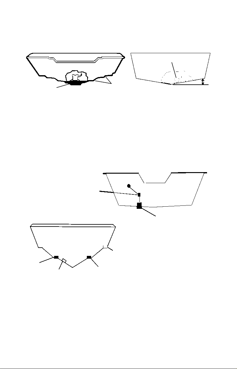
3. The transducer should be installed with its face pointing straight
down, if possible. For shoot-thru applications: Many popular fishing
boat hulls have a flat keel pad that offers a good mounting surface. On
vee hulls, try to place the transducer where the deadrise is 10° or less.
Deadrise less than 10°
Pad
Left, vee pad hull; right, vee hull. A pod style transducer is shown here,
but the principle is the same for Skimmers inside a hull.
Strakes
4. If the transducer is mounted on the transom, make sure it doesn't
interfere with the trailer or hauling of the boat. Also, don't mount it
closer than approximately one foot from the engine's lower unit. This
will prevent cavitation (bubble) interference with propeller operation.
5. If possible, route the transducer cable away from other wiring on the
boat. Electrical noise from engine wiring, bilge pumps and aerators can
be displayed on the sonar's screen. Use caution when routing the
transducer cable around these wires.
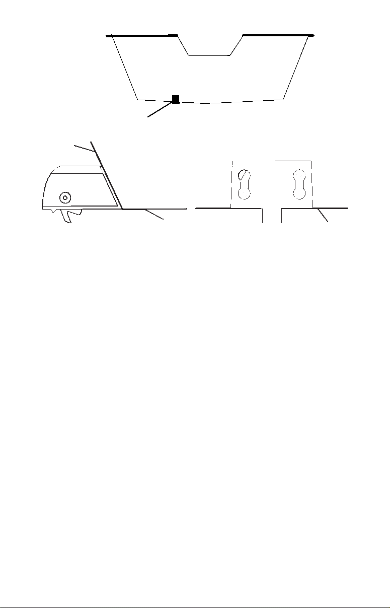
CAUTION: Clamp the
transducer cable to transom
near the transducer. This will
help prevent the transducer
from entering the boat if it is
knocked off at high speed.
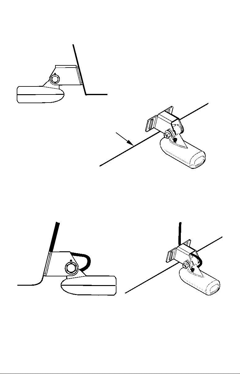
Good location
Poor location
Good
location
Poor angle
Good and poor transducer locations.
Good location
How low should you go?
For most situations, you should install your Skimmer transducer so
that its centerline is level with the bottom of the boat hull. This will
usually give you the best combination of smooth water flow and
protection from bangs and bumps.
5
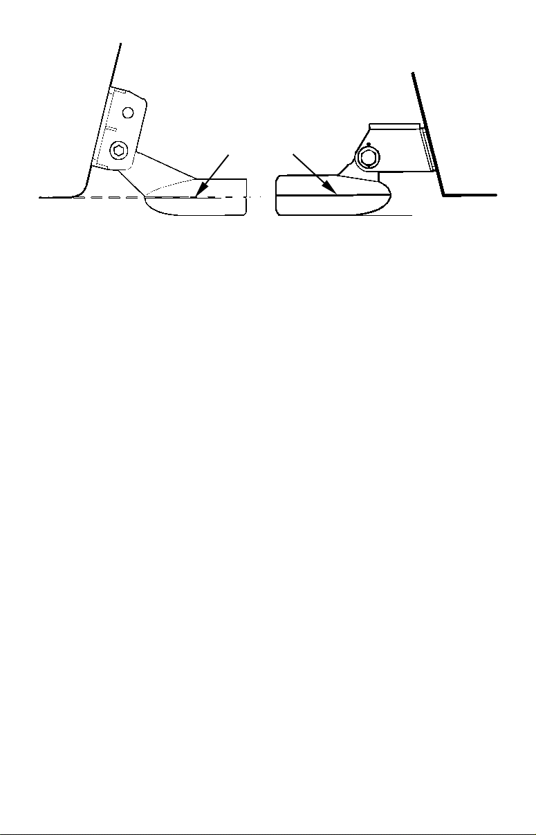
Transom
Transom
Transducer
centerline
Hull bottom
Align transducer centerline with hull bottom. A dual frequency
transducer is shown at left and a single frequency transducer at right.
Hull bottom
However, there are times when you may need to adjust the transducer
slightly higher or lower. (The slots in the mounting brackets allow you
to loosen the screws and slide the transducer up or down.) If you
frequently lose bottom signal lock while running at high speed, the
transducer may be coming out of the water as you cross waves or
wakes. Move the transducer a little lower to help prevent this.
If you cruise or fish around lots of structure and cover, your transducer
may be frequently kicking up from object strikes. If you wish, you may
move the transducer a little higher for more protection.
There are two extremes you should avoid. Never let the edge of the
mounting bracket extend below the bottom of the hull. Never let the
bottom – the face – of the transducer rise above the bottom of the hull.
Shoot-Thru-Hull vs. Transom Mounting
In a shoot-thru-hull installation, the transducer is bonded to the inside
of the hull with epoxy. The sonar "ping" signal actually passes through
the hull and into the water. This differs from a bolt-thru-hull
installation (often called simply "thru-hull"). In that case, a hole is cut
in the hull and a specially designed transducer is mounted through the
hull with a threaded shaft and nut. This puts the transducer in direct
contact with the water.
Typically, shoot-thru-hull installations give excellent high speed
operation and good to excellent depth capability. There is no possibility
of transducer damage from floating objects, as there is with a transommounted transducer. A transducer mounted inside the hull can't be
knocked off when docking or loading on a trailer.
However, the shoot-thru-hull installation does have its drawbacks.
First, some loss of sensitivity does occur, even on the best hulls. This
varies from hull to hull, even from different installations on the same
hull. This is caused by differences in hull lay-up and construction.
6

Second, the transducer angle cannot be adjusted for the best fish arches
on your sonar display. (This is not an issue for flasher-style sonars.)
Lack of angle adjustment can be particularly troublesome on hulls that
sit with the bow high when at rest or at slow trolling speeds.
Third, a transducer CAN NOT shoot through wood and metal hulls.
Those hulls require either a transom mount or a thru-hull installation.
Fourth, if your Skimmer transducer has a built in temp sensor, it will
only show the temperature of the bilge, not the water surface temp.
Follow the testing procedures listed in the shoot-thru-hull installation
section at the end of this instruction booklet to determine if you can
satisfactorily shoot through the hull.
Transom Transducer Assembly and Mounting
The best way to install these transducers is to loosely assemble all of
the parts first, place the transducer's bracket against the transom and
see if you can move the transducer so that it's parallel with the ground.
The following instructions sometimes vary depending on the mounting
bracket that came with your transducer. Single frequency Skimmers
come with a one-piece stainless steel bracket, while dual frequency
Skimmers come with a two-piece plastic mounting bracket. Use the set
of instructions that fits your model.
1. Assembling the bracket.
A. One-piece bracket: Press the two small plastic ratchets into the
sides of the metal bracket as shown in the following illustration. Notice
there are letters molded into each ratchet. Place each ratchet into the
bracket with the letter "A" aligned with the dot stamped into the metal
bracket. This position sets the transducer's coarse angle adjustment for a
14° transom. Most outboard and stern-drive transoms have a 14° angle.
Dot
Align plastic ratchets in bracket.
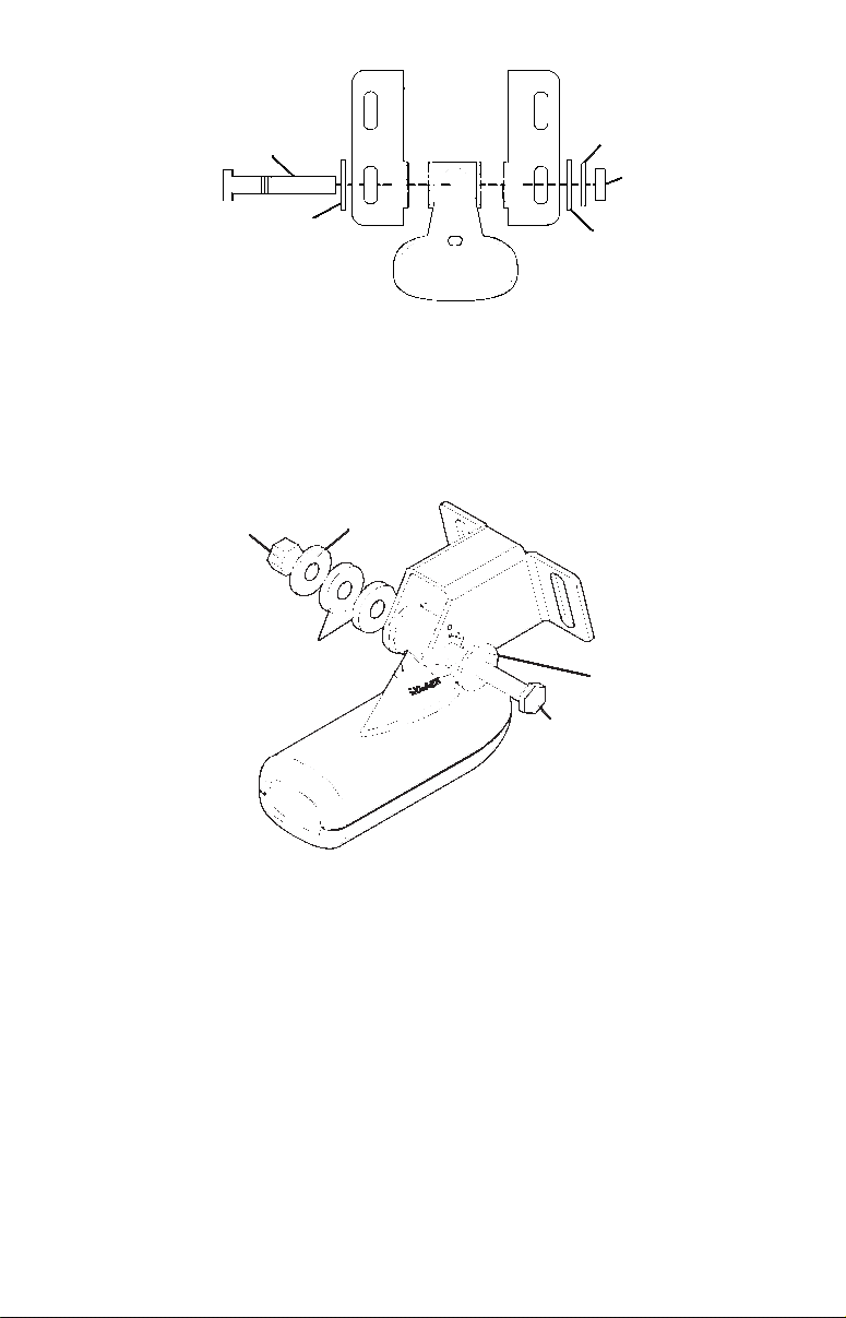
B. Two-piece bracket: Locate the four plastic ratchets in the
transducer's hardware package. Press two ratchets into the sides of
the plastic bracket and two on either side of the transducer as shown
in the following illustrations. Notice there are letters molded into each
ratchet. Place the ratchets into the bracket with the letter "A" aligned
7
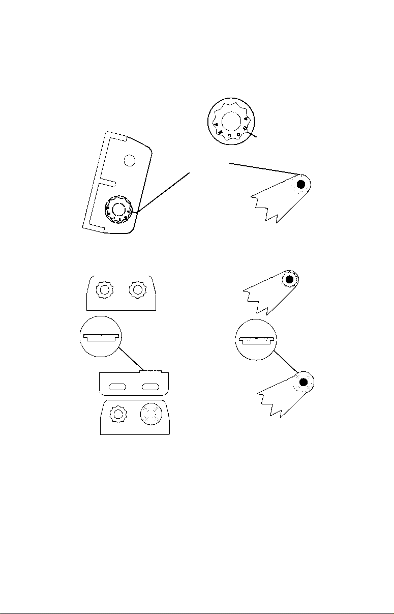
with the alignment mark molded into the bracket. Place the ratchets
onto the transducer with the letter "A" aligned with the 12 o'clock
position on the transducer stem. These positions set the transducer's
coarse angle adjustment for a 14° transom. Most outboard and sterndrive transoms have a 14° angle.
Alignment letters
Alignment
positions
Transducer
Transducer bracket
Insert and align ratchets.
Transducer
bracket
Transducer
Ratchet
Add ratchets to bracket and transducer.
Ratchet
2. Aligning the transducer on the transom.
A. One-piece bracket: Slide the transducer between the two
ratchets. Temporarily slide the bolt though the transducer assembly
and hold it against the transom. Looking at the transducer from the
side, check to see if it will adjust so that its face is parallel to the
ground. If it does, then the "A" position is correct for your hull.
If the transducer's face isn't parallel with the ground, remove the
transducer and ratchets from the bracket. Place the ratchets into the
8
holes in the bracket with the letter "B" aligned with the dot stamped
in the bracket.
Reassemble the transducer and bracket and place them against the
transom. Again, check to see if you can move the transducer so it's
parallel with the ground. If you can, then go to step 3A. If it doesn't,
repeat step 2A, but use a different alignment letter until you can
place the transducer on the transom correctly.
Ratchets
Insert bolt and check transducer position on transom.
B. Two-piece bracket: Assemble the transducer and bracket as
shown in the following figure. Temporarily slide the bolt though the
transducer assembly but don't tighten the nut at this time. Hold the
assembled transducer and bracket against the transom. Looking at the
transducer from the side, check to see if it will adjust so that its face is
parallel to the ground. If it does, then the "A" positions are correct for
your hull.
If the transducer's face isn't parallel with the ground, remove and
disassemble the transducer and ratchets. Place the ratchets into the
bracket holes with the letter "B" aligned with the bracket alignment
mark. Place them on the transducer aligned with the 12 o'clock
position on the transducer stem.
Reassemble the transducer and bracket and place them against the
transom. Again, check to see if you can move the transducer so it's
parallel with the ground. If you can, then go to step 3B. If it doesn't,
repeat step 2B, but use a different alignment letter until you can
place the transducer on the transom correctly.
9
Bolt
Lock washer
Nut
Flat washer
Assemble transducer and bracket.
Flat washer
3. Assembling the transducer.
A. One-piece bracket: Once you determine the correct position for
the ratchets, assemble the transducer as shown in the following
figure. Don't tighten the lock nut at this time.
Metal
Nut
Rubber
washers
washer
Metal washer
Bolt
Assemble transducer and bracket.
B. Two-piece bracket: Once you determine the correct position for
the ratchets, assemble the transducer as shown in the figure in step
2B. Don't tighten the lock nut at this time.
4. Drilling mounting holes.
Hold the transducer and bracket assembly against the transom. The
transducer should be roughly parallel to the ground. The
transducer's centerline should be in line with the bottom of the hull.
Don't let the bracket extend below the hull!
Mark the center of each slot for the mounting screw pilot holes. You
will drill one hole in the center of each slot.
10
Drill the holes. For the one-piece bracket, use the #29 bit (for the #10
screws). For the two-piece bracket, use the #20 bit (for the #12
screws).
Transom
Transom
Position transducer mount on transom and mark mounting holes.
Side view shown at left and seen from above at right.
5. Attaching transducer to transom.
A. One-piece bracket: Remove the transducer from the bracket and
re-assemble it with the cable passing through the bracket over the
bolt as shown in the following figures.
For single frequency Skimmer, route cable over bolt and through
bracket. Side view shown at left and seen from above at right.
Both bracket types: Attach the transducer to the transom. Slide the
transducer up or down until it's aligned properly with the bottom of
the hull as shown in the preceding and following figures. Tighten the
11
bracket's mounting screws, sealing them with the sealant/adhesive
compound.
Adjust the transducer so that it's parallel to the ground and tighten
the nut until it touches the outer washer, then add 1/4 turn. Don't
over tighten the lock nut! If you do, the transducer won't "kick-up" if
it strikes an object in the water.
Bottom
of
hull
Flat-bottom hull
Align transducer centerline with hull bottom and attach transducer to
transom. Rear view of dual frequency Skimmer shown.
Deep-"vee" hull
6. Route the transducer cable through or over the transom to
the sonar unit. Make sure to leave some slack in the cable at the
transducer. If possible, route the transducer cable away from other
wiring on the boat. Electrical noise from the engine's wiring, bilge
pumps, VHF radio wires and cables, and aerators can be picked up by
the sonar. Use caution when routing the transducer cable around
these wires.
WARNING:
Clamp the transducer cable to the transom close to the
transducer. This can prevent the transducer from
entering the boat if it is knocked off at high speed.
If you need to drill a hole in the transom to pass the connector through,
the required hole size will depend on the connector on the end of your
transducer's cable. If the transducer has a manual locking collar
connector, you will need to drill a 1" hole. If it has a push-on selfsealing connector, you will need to drill a 5/8" hole.
12
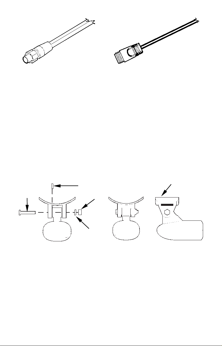
Manual locking collar connector Push-on self-sealing connector
requires a 1" hole. requires a 5/8" hole.
Caution:
If you drill a hole in the transom for the cable, make sure it is
located above the waterline. After installation, be sure to seal the
hole with the same marine grade above- or below-waterline
sealant/adhesive used for the mounting screws.
7. Make a test run to determine the results. If the bottom is lost at
high speed, or if noise appears on the display, try sliding the
transducer bracket down. This puts the transducer deeper into the
water, hopefully below the turbulence causing the noise. Don't allow
the transducer bracket to go below the bottom of the hull!
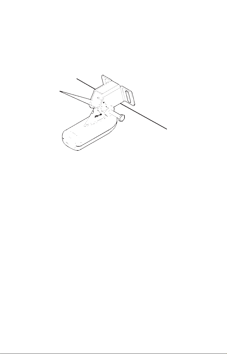
Trolling Motor Bracket Installation
1. Attach the TMB-S bracket to the transducer as shown in the
following figure, using the hardware supplied with the transducer.
(Note: The internal tooth washer is supplied with the TMB-S.)
TMB-S
bracket
Bolt
Internal tooth washer
Nut
Flat washer
Attach motor mounting bracket to transducer.
2. Slide the adjustable strap supplied with the TMB-S through the slot
in the transducer bracket and wrap it around the trolling motor.
Position the transducer to aim straight down when the motor is in the
water. Tighten the strap securely.
3. Route the transducer cable alongside the trolling motor shaft. Use
plastic ties (not included) to attach the transducer cable to the trolling
motor shaft. Make sure there is enough slack in the cable for the motor
to turn freely. Route the cable to the sonar unit and the transducer is
ready for use.
13
Transducer mounted on trolling motor, side view.
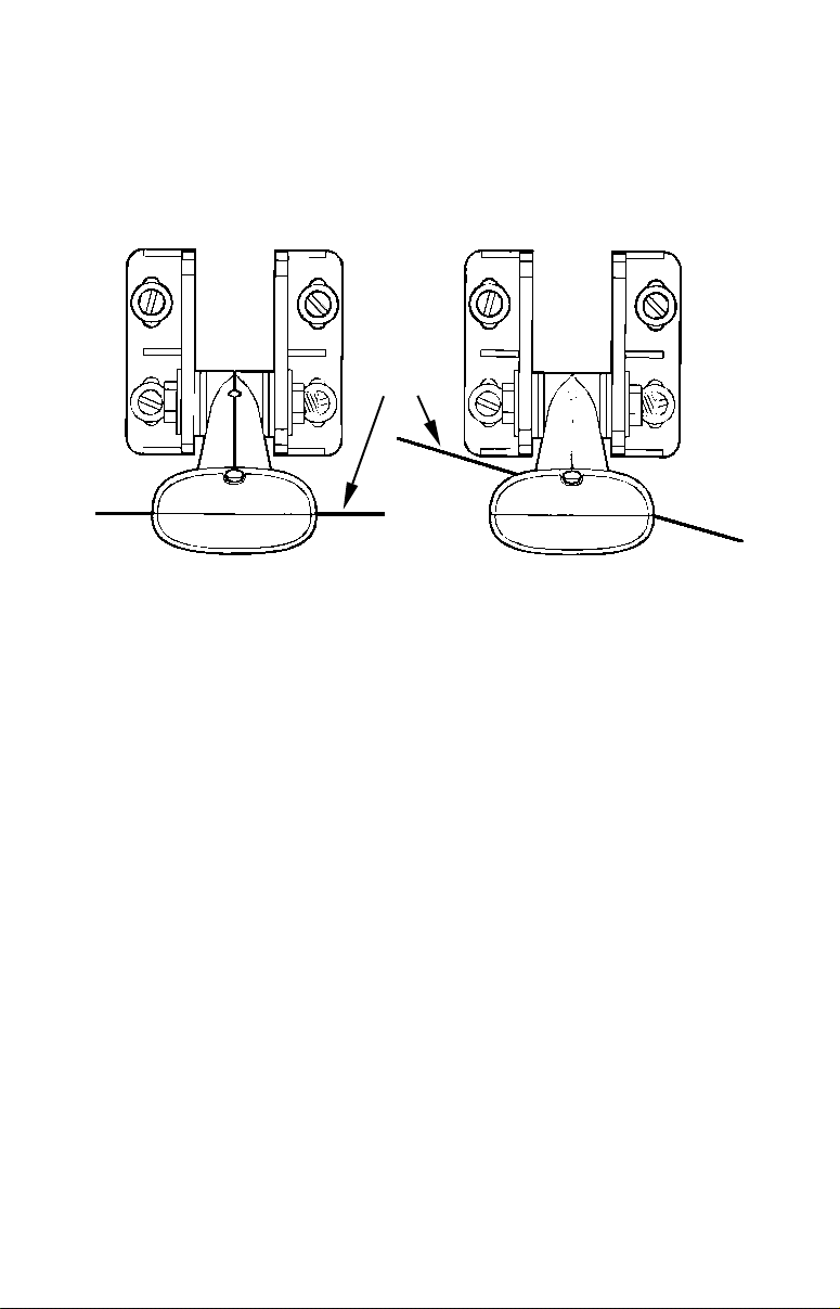
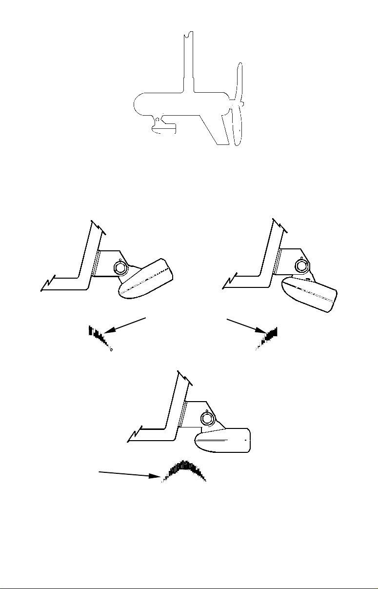
Transducer Orientation and Fish Arches
If you do not get good fish arches on your display, it could be because
the transducer is not parallel with the ground when the boat is at rest
in the water or at slow trolling speeds.
Partial fish arches
Transducer aimed
too far back
Transducer aimed
too far forward
Full fish arch
Proper transducer angle
Transducer angles and their effects on fish arches.
If the arch slopes up – but not back down – then the front of the
transducer is too high and needs to be lowered. If only the back half of
14
the arch is printed, then the nose of the transducer is angled too far
down and needs to be raised.
NOTE:
Periodically wash the transducer's face with soap and water to
remove any oil film. Oil and dirt on the face will reduce the
sensitivity or may even prevent operation.
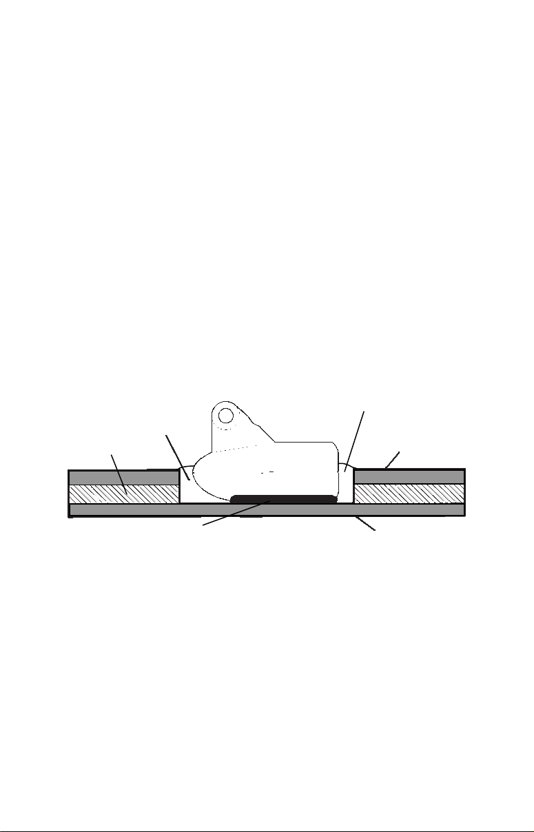
Shoot-Thru-Hull Preparation
The transducer installation inside a fiberglass hull must be in an area
that does not have air bubbles in the resin or separated fiberglass
layers. The sonar signal must pass through solid fiberglass. A
successful transducer installation can be made on hulls with flotation
materials (such as plywood, balsa wood or foam) between layers of
fiberglass if the material is removed from the chosen area. See the
figure below.
WARNING:
Do not remove any material from your inner hull unless
you know the hull's composition. Careless grinding or
cutting on your hull can result in damage that could
sink your boat. Contact your boat dealer or
manufacturer to confirm your hull specifications.
Fill with resin
Fill with resin
Flotation material
Inner hull
Epoxy to hull first
Epoxy the transducer to a solid portion of the hull.
Outer hull
For example, some (but not all) manufacturers use a layer of fiberglass,
then a core of balsa wood, finishing with an outer layer of fiberglass.
Removing the inner layer of fiberglass and the balsa wood core exposes
the outer layer of fiberglass. The transducer can then be epoxied
directly to the outer layer of fiberglass. After the epoxy cures for 24
hours, fill the remaining space with polyester resin. When the job is
finished, the hull is watertight and structurally sound. Remember, the
sonar signal must pass through solid fiberglass. Any air bubbles in the
fiberglass or the epoxy will reduce or eliminate the sonar signals.
15
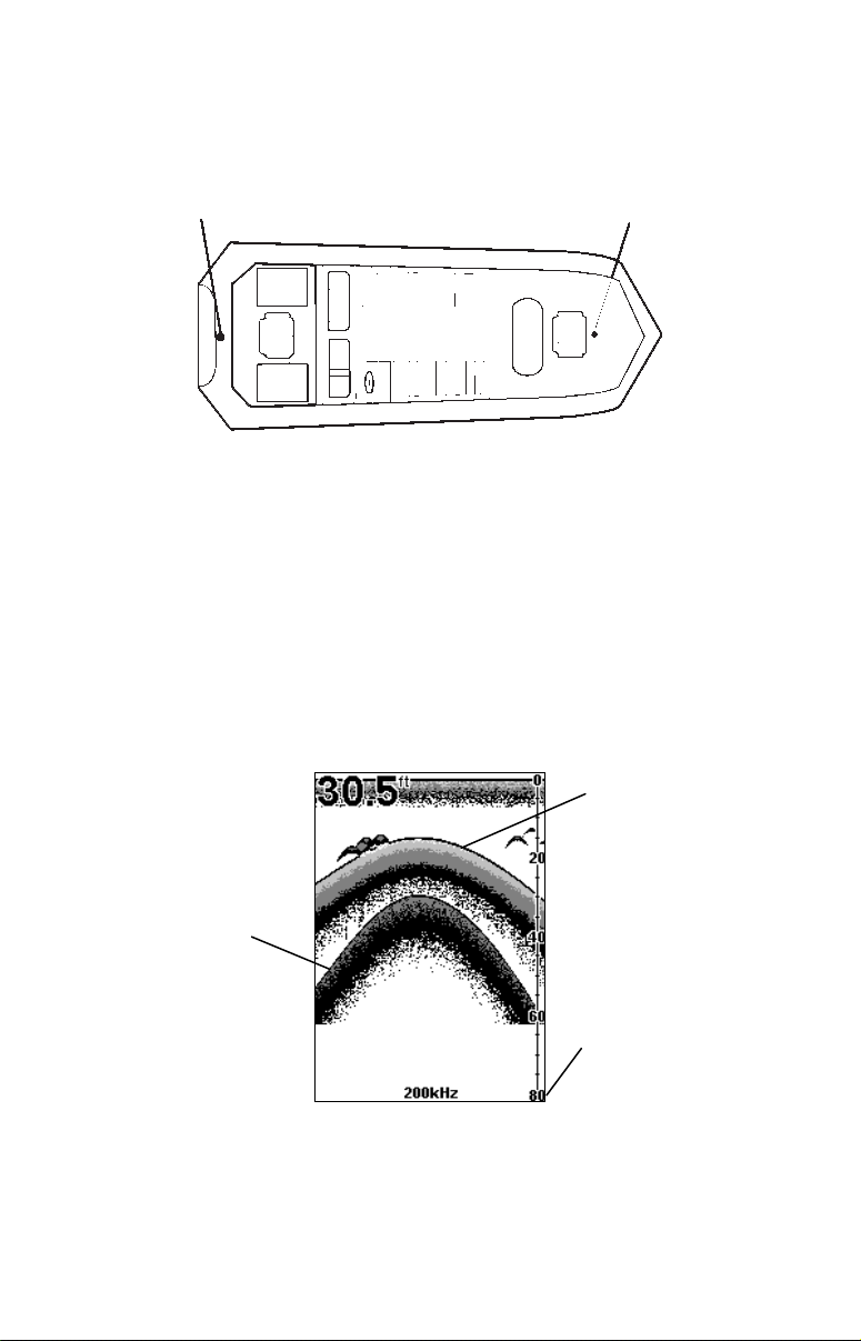
Testing Determines Best Location
Ideally, the shoot-thru transducer should be installed as close to the
transom as possible, close to the centerline. This will give you the best
performance during high speed maneuvers.
Transducer location
(high speed)
Shoot-thru-hull transducer locations for
high speed or trolling speed operation.
Transducer location
(trolling speed)
To choose the proper location for shoot-thru-hull mounting, follow these
testing procedures: (You may need a helper to complete these steps.)
1. Anchor the boat in about 30 feet of water. Add a little water to the
sump of the boat. Plug the transducer into the sonar unit, turn it on,
then hold the transducer over the side of the boat in the water. Adjust
the sensitivity and range controls until a second bottom echo is seen on
the display. (You'll need to turn off Auto Sensitivity, Auto Depth Range
and ASP. Try a range setting that is two to three times the water
depth. The harder (more rocky) the bottom, the easier it will be to get a
second bottom signal.) Don't touch the controls once they've been set.
True bottom
Second bottom
Manual range setting
Example of a second bottom signal. Unit is in 30 feet of water, with
range set at 80 feet and sensitivity set at 87 percent.
2. Next, take the transducer out of the water and place it in the water
in the sump of the boat, face down. (The transducer face is shown in the
16

figure on the following page.) Notice how the signal strength decreases.
The second bottom signal will probably disappear and the bottom signal
intensity will likely decrease.
3. Now move the transducer around to find the best location with the
strongest possible bottom signal. If you find a spot with an acceptable
bottom signal, mark the location and move on to step 4.
If you can't get an acceptable bottom signal, try turning up the sensitivity
by three or five keystrokes and then move the transducer around once
more. If you find a spot that works, mark it and move on to step 4.
If you have to turn up sensitivity by more than five keystrokes to get a
good signal, the transducer should be mounted on the outside of the
hull. This is especially true if you have to turn sensitivity all the way
up to get a decent bottom signal.
4. Most people can get good results by following steps 1 through 3, so
this step is optional. If you want to make an extra effort to be
absolutely sure that your selected location will work under all
conditions, make a test run with the boat on plane and observe the
bottom signal. You'll need to figure some way to prop the transducer
into position while you make your test run. (A brick or two might be
sufficient to hold it in place.)
5. When you're satisfied with a location, mark it and proceed with
the installation.
Shoot-Thru-Hull Installation
If you are installing the transducer on a hull with flotation material
sandwiched within the hull, refer to the subsection "Shoot-Thru-Hull
Preparation,” beginning on page 15.
1. Make sure the area is clean, dry and free of oil or grease, then sand
both the inside surface of the hull and the face of the transducer with
100 grit sandpaper. The sanded hull area should be about 1-1/2 times
the diameter of the transducer. The surface of the hull must be flat so
the entire transducer face is in contact with the hull prior to bonding.
After sanding, clean the hull and transducer with rubbing alcohol to
remove any sanding debris.
WARNING:
Use only the epoxy available from LEI. It has been
formulated to work with these installation procedures.
Other epoxy types may be too thin or may not cure to the
right consistency for optimum transducer performance.
17
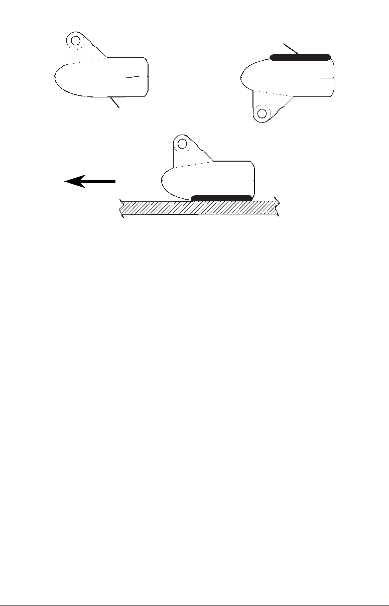
Spread epoxy here
Sand this surface
(unit's face)
Orient the Skimmer
with the nose facing
the bow of the boat.
To bow
Epoxy transducer to hull.
2. The epoxy consists of the epoxy itself and a hardener. Remove the
two compounds from the package and place them on the paper plate.
Thoroughly stir the two compounds together until the mixture has a
uniform color and consistency. Do not mix too fast or bubbles will form
in the epoxy. After mixing, you have 20 minutes to complete the
installation before the epoxy becomes unworkable.
Spread a thin layer of epoxy (about 1/16" or 1.5 mm thick) on the face of
the transducer as shown in the previous figure. Make sure there are no
air pockets in the epoxy layer! Then, apply the remaining epoxy to the
sanded area on the hull.
3. Press the transducer into the epoxy, twisting and turning it to force
any air bubbles out from under the transducer face. Stop pressing when
you bottom out on the hull. When you're finished, the face of the
transducer should be parallel with the hull, with a minimum amount of
epoxy between the hull and transducer.
4. Apply a weight, such as a brick, to hold the transducer in place while
the epoxy cures. Be careful not to bump the transducer while the epoxy
is wet. Leave the weight in place for a minimum of three hours. Allow
the epoxy to cure for 24 hours before moving the boat.
5. After the epoxy has cured, route the cable to the sonar unit and it's
ready to use.
18

Speed/Temperature Sensors
Optional Temperature Sensor
All the units in this series can display water temperature from a single
analog sensor. Your unit comes packed with a transducer with a temp
sensor built into it. If you wish to purchase an optional additional
sensor for your unit, refer to the accessory ordering information inside
the back cover of this manual.
However, please note that the Sonar socket on your unit is designed to
read only one temp sensor. Since your transducer contains a built-in
temp sensor, attaching the optional temp sensor to your unit's Sonar
socket will override the temperature information provided by the
transducer's temp sensor. Your unit will only display the temperature
provided by the optional sensor.
Optional Speed Sensor Installation
All the units in this series can display speed and distance traveled, but
only the X59DF comes packed with a speed sensor. If you wish to
purchase an optional additional sensor for your unit, refer to the
accessory ordering information inside the back cover of this manual.
The following instructions describe how to install the speed sensor.
Recommended tools for this job include: drill, 7/8" drill bit, 1/8" drill bit
for pilot holes, screwdriver. Required supplies for this job include: four
#8 stainless steel wood screws (3/4" long), high quality, marine grade
above- or below-waterline sealant.
First find a location on the boat's transom where the water flow is
smoothest. Don't mount the sensor behind strakes or ribs. These will
disturb the water flow to the speed sensor. Make sure the sensor will
remain in the water when the boat is on plane. Also make sure the
location doesn't interfere with the boat's trailer. Typically, the sensor is
mounted about one foot to the side of the transom's centerline.
Once you've determined the proper location for the unit, place the
sensor on the transom. The bottom of the bracket should be flush with
the hull's bottom. Using the sensor as a template, mark the hull for the
screws' pilot holes. Drill four 1/8" holes, one in each end of the slots.
Mount the sensor to the hull using #8 stainless steel wood screws (not
included). Use a high quality, marine grade above- or below-waterline
sealant to seal the screws. Make sure the sensor is flush with the
bottom of the hull and tighten the screws.
19
Good location
Stern view showing good location for mounting sensor on transom.
Transom
Bottom of hull
Speed sensor mounting configuration:
side view (left) and rear view (right.)
Bottom of hull
If the base of the transom has a radius, fill the gap between the
transom and the sensor with the sealant. This will help ensure a
smooth water flow.
Route the sensor's cable through or over the transom to the sonar unit.
If you need to drill a hole in the transom to pass the connector through,
the required hole size is 7/8".
CAUTION:
If you drill a hole in the transom for the cable, make sure it is
located above the waterline. After installation, be sure to seal the
hole with the same marine grade above- or below-waterline
sealant used for the screws.
The sensor is now ready for use. Connect the sensor to the sonar socket
on the back of your unit and connect the transducer to the speed
sensor's socket. If you have any questions concerning the installation of
the sensor, please contact your local boat dealer.
Power Connections
Your unit comes with a power/data cable that splits into three ends,
each with several exposed wires (shown in the following figure). The
end with 4 wires (blue, yellow, orange and shield) is a data cable that
connects to a NMEA 0183 interface; the cable label says "RS-232
COMM". The end with three wires (red, black and shield) is a power
cable that supports a NMEA 2000
buss; the cable label says "NMEA
20
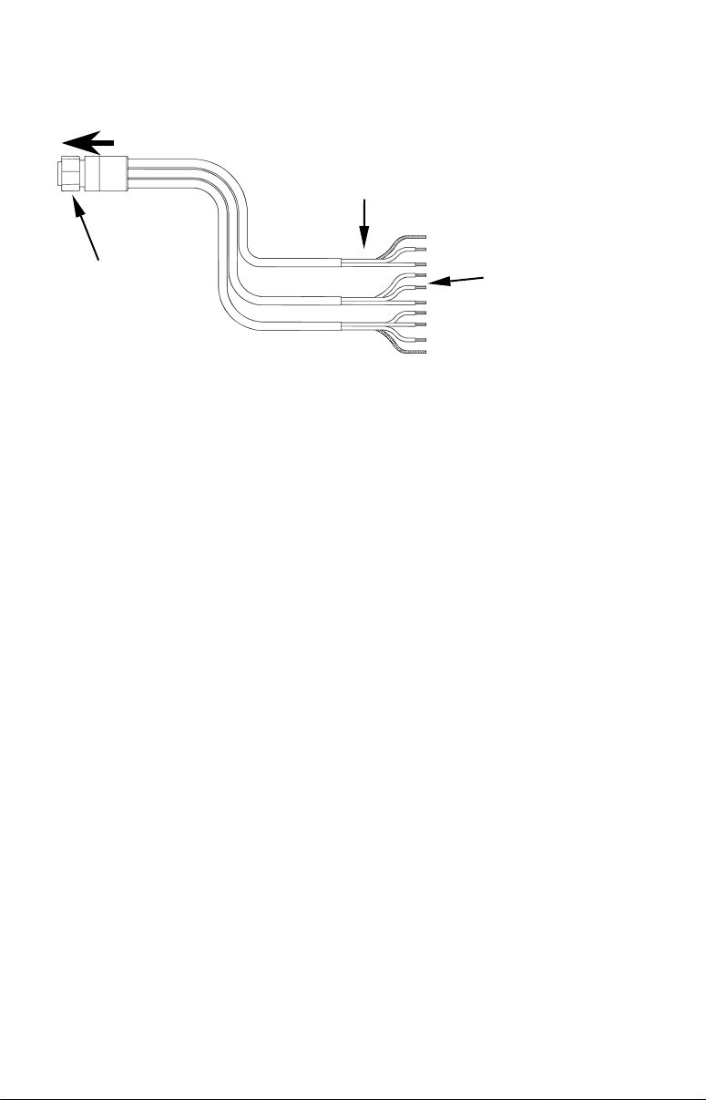
2000 Power". The thicker three-wire cable (red, black and white) is the
Power Supply for your unit (and optional external speaker connection
for some units); it has no label on the cable.
To unit
Power Supply wires:
red, black and white
Blue connector
The Power/Data cable for this unit.
NMEA 2000 Power wires:
red, black and shield
Data Cable wires: blue,
yellow, orange and shield
Depending on your configuration, you may not use all of these wires.
(For example, many units cannot operate an optional external speaker,
so the white wire on the Power Supply cable isn't functional.) The
following segments include instructions for installing all the wires that
you will use with this unit.
Powering a NMEA 2000 Buss
(NMEA 2000 Power cable)
A NMEA 2000 buss must be connected to a power source to operate. If
you have a pre-existing NMEA 2000 installation, it may already be
connected to another power source. If your NMEA 2000 buss is already
powered, you can ignore the NMEA 2000 Power cable. Never attach
two power sources to a single NMEA 2000 buss.
If you do need to power your NMEA 2000 buss, attach the NMEA 2000
Power cable to your boat's battery just as indicated in the following
segment for connecting your unit's Power Supply cable. The NMEA
2000 Power cable's red wire should be attached (with provided 3-amp
fuse) to the boat battery's positive terminal, and the NMEA 2000 Power
cable's black and shield wires should both be attached to the battery's
negative terminal.
Powering Your Unit
(Power Supply cable – red and black wires)
The unit works from a 12-volt battery system. For the best results,
attach the power cable directly to the battery. You can attach the power
cable to an accessory or power buss, however you may have problems
21

with electrical interference. Therefore, it's safer to go ahead and attach
the power cable directly to the battery.
CAUTION:
When using the unit in a saltwater environment, we strongly
recommend that you shut off the power supply to the power cable
when the unit is not in use. When the unit is turned off but still
connected to a power supply, electrolysis can occur in the power
cable plug. This may result in corrosion of the plug body along with
the electrical contacts in the cable and the unit's power socket.
In saltwater environments we recommend you connect the power
cable to the auxiliary power switch included in most boat designs.
If that results in electrical interference, or if such a switch is not
available, we recommend connecting direct to the battery and
installing an inline switch. This will let you shut off power to the
power cable when the unit is not in use. When you are not using
the unit, you should always shut off power to the power cable,
especially when the power cable is disconnected from the unit.
If possible, keep the power cable away from other boat wiring, especially
the engine's wires. This will provide the best isolation from electrical
noise. If the cable is not long enough, splice #18 gauge wire onto it. The
power cable has two wires, red and black. Red is the positive lead, black
is negative or ground. (There is also a white wire to power an optional
external speaker for some units. This unit does not use a speaker, so to
prevent an electrical short, we recommend capping the exposed speaker
wire end with a wire nut or electrical tape) Make sure to attach the inline fuse holder to the red lead as close to the power source as possible.
For example, if you have to extend the power cable to the battery or
power buss, attach one end of the fuse holder directly to the battery or
power buss. This will protect both the unit and the power cable in the
event of a short. It uses a 3-amp fuse.
22
 Loading...