

Page 1
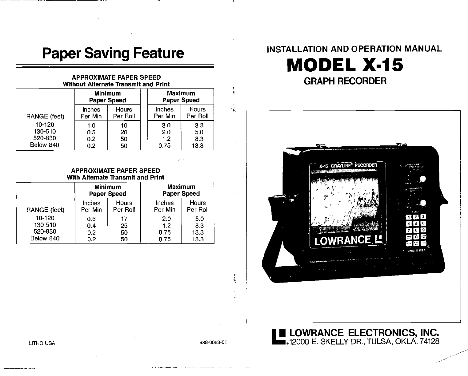
Paper
RANGE
10-120
130-510
520-830
Below 840
RANGE
10-120
130-510
520-830
Below 840
Saving
APPROXIMATE PAPER
Without Alternate Transmit and Print
Minimum
Paper Speed
Inches Hours Inches Hours
(feet)
(feet)
Per Mm Per
1.0 10 3.0 3.3
0.5 20 2.0 5.0
0.2 50
0.2 50
APPROXIMATE PAPER SPEED
With Alternate Transmit and Print
Minimum Maximum
Paper Speed
Inches Hours
Per Mm Per Roll Per Mm Per Roll
0.6 17 2.0 5.0
0.4
0.2 50 0.75 13.3
0.2 50 0.75 13.3
Feature
SPEED
Roll Per Mm Per Roll
—
25 1.2 8.3
Maximum
Paper Speed
1.2 8.3
0.75 13.3
Paper Speed
Inches Hours
INSTALLATION AND
MODEL X-15
GRAPH RECORDER
OPERATION MANUAL
INC.
LITHO USA
988-0083-01
• LOWRANCE
12OOO
E.
SKELLY
ELECTRONICS,
DR., TULSA,
OKLA. 74128
PDF compression, OCR, web-optimization with CVISION's PdfCompressor
Page 2
E'l
I!
L 30
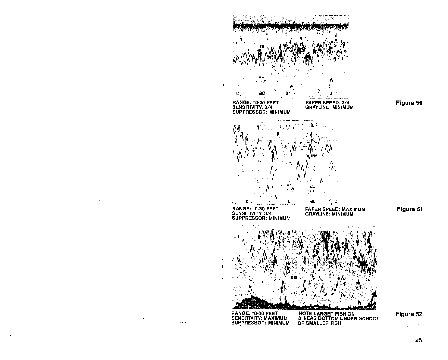
RANGE: 10-30 FEET
SENSITIVITY: 3/4
SUPPRESSOR: MINIMUM
ft
1
U,
RANGE: 10-30 FEET
SENSITIVITY:
SUPPRESSOR: MINIMUM
A
&
L
I-
A
3/4
-i
5
U
PAPER SPEED: 3/4
GRAYLINE: MINIMUM
:4
JO
PAPER SPEED: MAXIMUM
GRAYLINE: MINIMUM
Figure
Figure
50
51
RANGE: 10-30 FEET
SENSITIVITY: MAXIMUM
SUPPRESSOR: MINIMUM
NOTE
LARGER FISH ON
& NEAR
OF
BOTTOM UNDER SCHOOL
SMALLER
FISH
Figure
52
25
PDF compression, OCR, web-optimization with CVISION's PdfCompressor
Page 3
INDEX
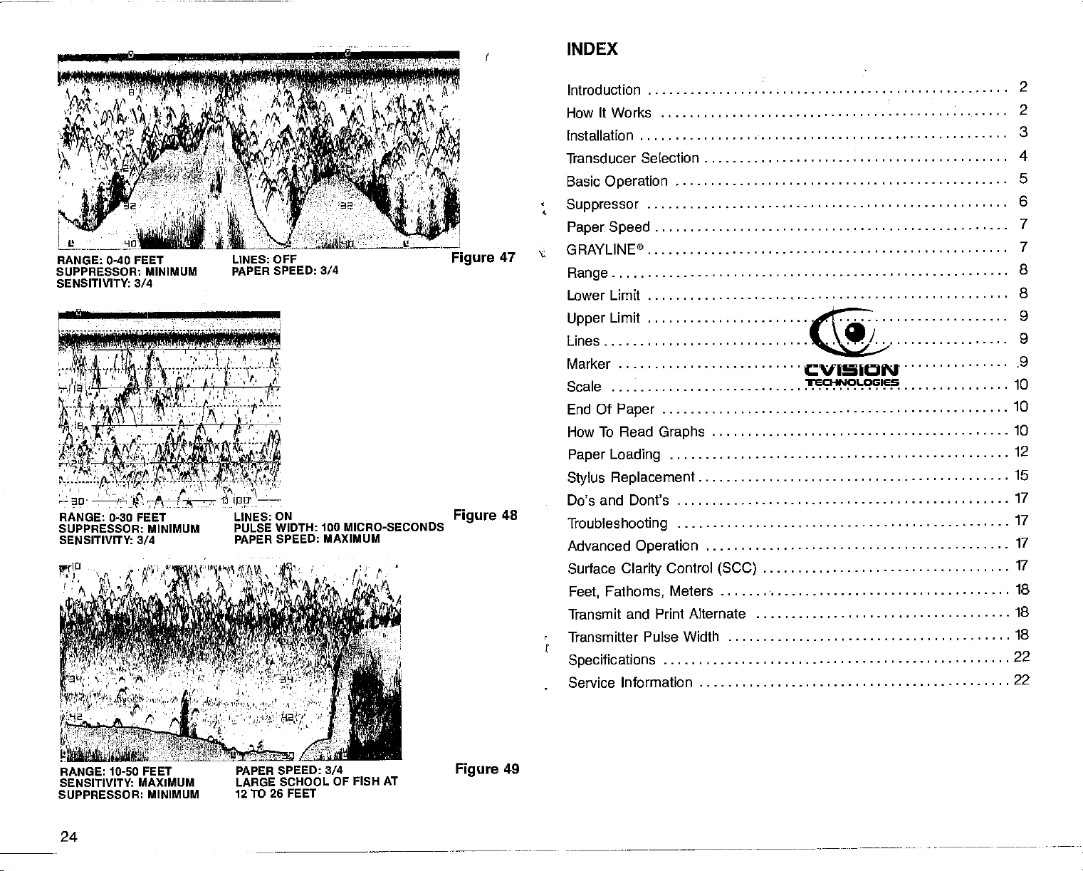
RANGE: 0-40
SUPPRESSOR:
SENSITIVITY: 3/4
FEET LINES: OFF
MINIMUM PAPER SPEED: 3/4
.7
RANGE: 0-30 FEET LINES:
SUPPRESSOR: MINIMUM
SENSITIVITY: 3/4
PULSE WIDTH: 100 MICRO-SECONDS
PAPER SPEED: MAXIMUM
ON
Figure
Figure
47
48
Introduction
It Works
How
Installation
Transducer Selection
Basic
Operation
Suppressor
Speed
Paper
GRAYLINE®
Range
Lower Limit
Limit
Upper
Lines
Marker
Scale
End Of
How To Read
Paper
Stylus
Do's
Troubleshooting
Advanced
Surtace
Feet,
Transmit and
'
Transmitter Pulse Width
Specifications
Service Information
.
Paper
Graphs
Loading
Replacement
and Dont's
Operation
Clarity
Fathoms,
Print Alternate
Control
Meters
(SCC)
2
2
3
4
5
S
7
7
8
8
9
9
9
10
10
10
12
15
17
17
17
17
18
18
18
22
22
RANGE: 10-50 FEET
SENSITIVITY: MAXIMUM
SUPPRESSOR: MINIMUM
PDF compression, OCR, web-optimization with CVISION's PdfCompressor
24
PAPER SPEED: 3/4
LARGE
12 TO 26
SCHOOL OF FISH AT
FEET
Figure
49
Page 4
I
INTRODUCTION
The
Lowrance X-15 is a
sophisticated
sounder.
the
puter,
other
any
price range.
tem is at
the
changing
bottom
and boat
the unit's
pression level,
speed,
line" used to
corded information.
Lowrance
system
signals
but is
ones,
line function to
gray
signals
permanent
sonar
has "seen" is
recording depth
Thanks to a microcom-
X-15 can do more than
sounder in its
depth
Full control of the
your
finger tips
demands of
conditions,
speed.
sensitivity setting, sup-
and
the
variable
not
only
without
under all
record of what
water
You can select
depth range, paper
degree
enhance the re-
The
suppression
filters out false
distorting
synchronized
provide
conditions. The
roiled and
stored inside the case.
Small boat sonar
routinely
depth,
used to
examine bottom
and locate fish. The
the
X-15
goes
ordinary.
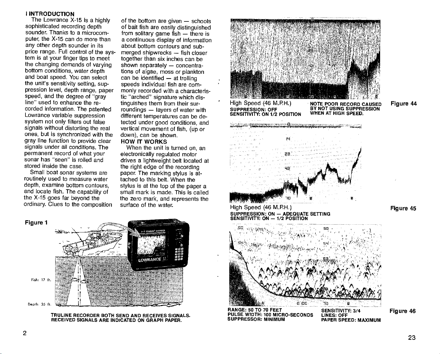
Figure
Clues to
1
systems
measure water
capability
far
beyond
the
highly
sys-
to meet
varying
depth
of
gray
patented
the real
with the
clear
your
are
contours,
of
the
composition
of the bottom are
of bait fish are
from
solitary game
a continuous
about bottom
merged shipwrecks
together
shown
tions of
can be identified
speeds
monly
tic "arched"
tinguishes
roundings
different
tected under
vertical
down),
HOW IT WORKS
When the unit
electronically
drives a
the
paper.
tached to this
stylus
small mark is made.
the zero
surface of the
than six
separately
algae,
individual fish are
recorded with
them from their sur-
—
temperatures
movement of
can
lightweight
right edge
The
marking stylus
is at
the
mark,
given
easily distinguished
display
contours and sub-
inches can be
—
moss or
—
signature
layers
good conditions,
be shown.
is turned
regulated
of the
belt. When the
of the
top
and
water.
—
schools
—
fish
there is
of
information
—
fish closer
concentra-
plankton
at
trolling
com-
a characteris-
which
dis-
of water
with
can be de-
and
(up
on,
motor
or
an
fish,
belt located at
recording
is at-
a
paper
This is called
represents
the
High Speed
SUPPRESSION: OFF
SENSITIVITY: ON 1/2 POSITION
-
-i —,_.—,,
High Speed (46 MPH.)
SUPPRESSION: ON
SENSITIVITY: ON
(46 M.F.H.)
-
I,.'
—
ADEQUATE SElliNG
—
1/2 POSITION
a -
t''.'9ø'a't
NOTE POOR
BY NOT USING
WHEN AT HIGH
RECORD CAUSED
t - -
I,
1
SUPPRESSION
SPEED.
Figure
Figure
44
45
s
Fith 17 ft.
35 ft.
Depth
TRULINE RECORDER BOTH SEND AND
RECEIVED SIGNALS ARE
INDICATED ON GRAPH
RECEIVES
PAPER.
SIGNALS.
PULSE WIDTH: 100
SUPPRESSOR: MINIMUM
MICRO-SECONDS LINES: OFF
RANGE: 50 TO 70 FEET
2
PDF compression, OCR, web-optimization with CVISION's PdfCompressor
SENSITIVITY:
PAPER SPEED:
3/4
MAXIMUM
Figure
46
23
Page 5
SPECIFICATIONS — X-15
Depth Ranges:
Feet, fathoms,
Operating Frequency:
192 kHz
second); accuracy
percent.
Pulse
Length:
(duration
(30-2000/ks
Operating Voltage:
Minimum: 10 volts DC
Maximum: 15 volts
Operating
0.7 to 1.8
printing density
power.
Output
Weight:
Dimension:
NOTICE
ducer
to
Power:
1600 watts
watts
(200
8.5 lb.
With Gimbal Mount:
Width
Height
Depth
Width
Periodically
(3.9 Kg)
-
12¼"
-
-
Instrument
-
Height
Depth
remove
-
-
Face with
meters.
(192,000
cycles per
is within 0.6
of
pulse):
programable)
Current:
amps
typical peak-to-peak.
RMS)
8%"
5¼"
Only:
91/2"
7½"
5¼"
wash the Trans-
any
200-1000/ks
DC
depending
and
output
and water
soap
oil film that
collect Oil and dirt on the
on
may
face
will reduce
sensitivity
or
may
even
prevent sounding.
GOT A PROBLEM? LET US
HELP!
If
have a
you
sonar
unit,
chance to
for
repair.
Assistance can often
tended
Write or call one
Service Centers or the Lowrance
Electronics, Inc.,
vice
(Toll-free
are
partment may
by
Department
1-800-331-3889).
Please detail
experiencing.
problem
please
before
help
telephone
of our Authorized
Customer
in
the
Our Service
be able
the inconvenience of
unit.
your
If it is determined
must be
structions will be
SCHEMATIC DIAGRAM AND
PARTS LIST
Diagram
Lowrance TRUELINE RECORD-
ER,
Lowrance
East
homa 74128. Be sure and
Should
send
Skelly
returned,
provided.
desire a Schematic
you
and Parts list for
to PARTS
$1.00
Electronics, Inc.,
Drive, Tulsa,
with
us a
give
sending
be ex-
or letter.
Ser-
OK.
Tulsa,
problem you
to save
returning
that
your
full
shipping
your
LIST,
12000
Okla-
give
your
it in
De-
you
unit
in-
the Model Number and Serial
Number of
INSTRUMENT.
your
SONAR
us
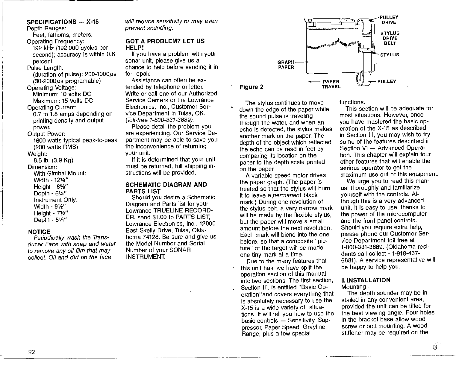
GRAPH
PAPER
Figure
down
the sound
through
echo is
another
depth
the echo can
comparing
paper
on the
the
treated
it to leave a
mark.) During
the
will be made
but
amount before
Each
before,
ture" of
one
-
this unit
operation
into two sections. The first section,
- Section
eration" and covers
is
X-15
tions. It will tell
basic controls
pressor,
Range, plus
2
The
the
of the
continues to move
stylus
the
detected,
edge
pulse
water,
of the
is
mark on the
object
paper
traveling
and when an
the
stylus
paper.
which reflected
be read in feet
its location on the
depth
speed
scale
motor drives
to the
paper.
A variable
paper graph. (The paper
so that the
stylus
the
paper
permanent
belt,
stylus
black
one revolution of
a
by
narrow mark
very
the flexible
will move a small
the next revolution.
mark will blend into the one
that a
so
the
mark at a time.
tiny
Due to the
has,
section of
Ill,
absolutely
is a wide
Paper Speed,
composite pic-
will be
target
features that
many
have
we
is entitled Basic
necessary
variety
you
—
a few
split
this manual
everything
to use the
of
how to use the
Sensitivity, Sup-
Grayline,
special
printed
will burn
made,
situa-
while
makes
The
by
is
stylus,
the
Op-
that
functions.
This section will
most situations. However,
have mastered
you
eration of the
in Section
some of the features
Section
tion. This
other features that
serious
maximum use out
We
ual
thoroughly
yourself
though
unit,
the
and the front
Should
please phone
vice
1-800-331-3889.
III, you may
—
VI
chapter
operator
urge you
with the controls.
this is a
it is
easy
of the
power
you require
Department
dents call collect
6881).
be
A service
happy
to
be
adequate
the basic
X-15 as described
wish to
described in
Advanced
will
explain
will enable the
to
the
get
of this
read this man-
to
and familiarize
advanced
very
to
panel
our Customer
help you.
thanks to
use,
microcomputer
controls.
extra
free at
toll
(Oklahoma
-
1-918-437-
representative
II INSTALLATION
Mounting
The
stalled in
provided
the best
in the bracket base
screw or bolt
stiffener
—
depth
any
the unit
viewing
may
sounder
convenient area,
may
can be tilted for
angle.
allow wood
mounting.
be
required
for
once
op-
try
Opera-
four
equipment.
Al-
help,
Ser-
resi-
will
be in-
Four holes
A wood
on the
PDF compression, OCR, web-optimization with CVISION's PdfCompressor
22
3
Page 6

back of thin
support
If the
than 18"
a trial run
the unit in
that the
affected.
Figure
BE SURE
ber
grommets
The
larger
of
grommet goes
gimbal
wiched between
fiberglass
the
X-15.
desired location is closer
to a
magnetic compass,
should be made with
operation
compass
3
readings
_________________
to insert the two rub-
on
gimbal
side
(larger diameter)
on inside of
bracket so
that it is sand-
gimbal
and sonar instrument
The
ings).
grommets provide
tion to hold the unit at
angle.
Power Connections
Twelve volt DC
sounder should
depth
the boat's 12-volt
by
tem.
The
tached to an
buss,
with
cable
to the
If a
ordinary
at
any
power
accessory
but if
electrical
you
should be attached
battery.
longer
cable is
#18
lamp
hardware or electronic
—
power
electrical
cable
have
interference,
cord available
panels
to be sure
are not
bracket.
bracket
draw-
(see
fric-
the desired
for
the
be
supplied
sys-
be at-
may
or
power
problems
the
directly
required,
sup-
to
use
store.
ply
dered. If this can't be
crimp-type splices. Tape
with
An
is
supplied
tain to
close
sible. This will
sonar unit
the event
connectors
the fuse
ble. The red
power
ductor. The
ground
The
cidental
damage
reversed. The unit
however,
is
applied.
Splices
electrical
in-line fuse
with the
install this fuse holder
to the
and the
a short occurs.
holder to the
cable is
conductor
graph
polarity
will occur if
until the
should be sol-
tape.
holder with fuse
X-15. Be cer-
power
are
source
protect
power
supplied
or white wire in the
the
positive
black wire is the
is
protected
reversals and no
the wires are
will not
proper polarity
Transducer Selection
Lowrance offers
of
transducers with
degree
cone
with
units. In
rance
used with
ducer of
out
loss of
use of
transducer will result
performance.
cone
that will
angle
of
our 192 kHz sonar
any
other
sonar instrument can be
any
the same
retuning
performance.
other manufacturer's
any
Now
you
can
you
either an 8
or 20
angle
interchange
words,
Lowrance trans-
of
any
frequency
any kind,
However,
in a loss of
select the trans-
use
done,
all
splices
as
as
pos-
both the
cable in
Crimp
to attach
power
ca-
con-
from
operate,
the choice
degree
Low-
with-
and no
ac-
the
To
return the unit to the
of the
micro-computer, simply
0 and
press
SCALES
then the LINES and
keys
This will revert
normal
Example:
Figure
operation.
Set the initial transmitter
pulse
micro-seconds.
'•.•
42
H
control
at the same time.
the unit back to
width
tolOO
A'
A':
'.
I :\'
A
Press:
LINES
Result:
Example:
Press:5,
and
LINES
Result:
Ii
•
'
0, then SCALES and
1,0,
together
Figure
Set the initial
pulse
Figure
'ii.
42
width
to5O
then SCALES
0,
together.
43
transmitter
'I
I
S
I
gs.
'Ii
I,
b
Figure
4
4
Ground
(Negative)
8
Figure
Qosci Iii
43
B
U
21
PDF compression, OCR, web-optimization with CVISION's PdfCompressor
Page 7

ducer
example,
set to 260
transmit
is.
390
pulse
from
initial
micro-seconds.
The transmitter
be increased from the initial
at
any
pressor
maximum amount of
with the LOWER LIMIT
the initial
feet,
width would be 260
pulse
If the LOWER LIMIT is set to
the initial transmit
feet,
would be 390
600
feet and
width remains
pulse
time
by
control clockwise. The
jts. Finally,
below,
pulse
rotating
pulse
the
at 600
width can
point
the
Sup-
width
added to the initial transmitter
width
pulse
microseconds.
the LOWER
feet,
trol is rotated to
ition,
would be 1220 micro-seconds.
(420
Earlier,
tionship
target separation.
increases,
resolution is
the
pulse
resolution becomes much better.
The X-15 allows
advantage
possible
transmitter
from what the
selects
Limit.
The
width can beset from
2000
keyboard
the initial
ting
width to 100
lution can be
equivalent
and 30
width is
tion! No other
today
PDF compression, OCR, web-optimization with CVISION's PdfCompressor
20:
is
approximately
In other
and the
LIMIT
Suppressor
set to 420
is
the maximum
the transmitter
initial + 800
we talked about the rela-
between
pulse
=
1220.)
pulse
As
pulse
target separation
degraded.
width is
decreased,
you
of this fact
to override the
width
pulse
micro-computer
according
initi?l
ps by entering
to the Lower
transmitter
it on the
as shown below.
transmitter
a three-inch
Its,
obtained,
to an inch and
initial transmitter
j.ts
equal
can
to one
graph
give you
inch resolu-
in the market
this
800
words,
con-
width
width and
width
or
However,
take
to
making
by
initial
setting
pulse
30
to
ts
By
pulse
reso-
50
1as
a
half,
pulse
feature.
if
pos-
set-
is
After
setting
pulse
trol can still be used to
noise
width.
For
transmitter
and the
tated to
pulse
turning
minimum will restore the unit to a
50
jis
The X-15 will
transmitter
tom of
ride the
guish
width from the
on the
of the
front
the initial transmitter
the
width,
by increasing
example,
Suppressor
maximum,
width would be 850
the
transmitter
the
micro-computer
suppressor
the
if a
SOjLs
width is
pulse
Suppressor
pulse
paper
control is
the transmitter
pulse
display
width at the bot-
when
cancel out
pulse
control
width.
the initial
you
the initial transmitter
scale
depth
a zero is
paper,
pulse
printed
width so that
two will not be confused. For
example,
pulse
the
transmitter
displayed
if
depth
a 100
width will be
as 0100. A 50
paper
pulse
as
will be
transmitter
Its
displayed
width would be
while a 50-foot
0050,
displayed
as 50. To
set the initial transmitter
width, simply press
width desired on the
pulse
it
keyboard,
LINES and SCALES
and then
same time.
(Note:
the amount of
press
keys
If the lines
and/or the scales were turned
this will turn
them back off
the SCALES
independently.
simultaneously.)
This will override
computer's
initial transmitter
desired
initial transmit
this
settings
trol is returned
computer.)
setting. (Note:
width will be fixed for all
until
back on. To turn
them
again, press
the LINES
or
key
Do not
press
the micro-
selection and set the
width to the
pulse
When an
width is
pulse
changed
or until con-
to the micro-
con-
initial
selected,
ro-
Re-
s.
to
over-
To distin-
pulse
printed
in
the
on
ts
pulse
the
both
at the
off,
either
key
them
set,
depth
•
•
design
best fit
wide cone
erally,
ers
(20 degrees)
for
operating
medium
cone
angle
more of the underwater
15 feet of water the 20
transducer covers an
bottom that's about 6 feet across.
The 8
degree
about a 2 foot circle.
only
Thus,
transducer when
gree
fish or
drop-offs
that are around
below
you.
transducer won't
gree
greater depths
degree
a
sharp drop-off
deep-water
deeper)
sharp drop-offs,
can sometimes be
angle
sirable because it can more accu-
detect the location of
rately
drop-off
In
deep
energy being
smaller
ducer can reach
Both the 8
degree
accurate bottom
though
wider on the
cause
bottom.
of
edge
the true
you
the
signal
are over
you
drop-offs.
of the 8
nal
merely
about the bottom's contours. This
and cone
your specific
in shallow
depths.
The
allows
needs.
angle
are
ideally
20
you
angle
transduc-
water or at
degree
to see
world. In
degree
area of the
transducer covers
looking
easily
. . . not
the
penetrate
20 de-
find
20
would use a
you
structure,
or
reefs,
However,
to
and to see
you
as well as the 8
transducer,
nor will
as well. In a
environment
or where
you're looking
(100
the narrow cone
more de-
without
water,
area,
Lowrance transducers
the bottom
you
Remember,
the
displaying
with the sound
concentrated in a
the 8
degree
to
greater
degree
20
are
and the
readings,
signal
degree
seeing
more
the shallow
shows
signal
depth.
tells
The rest of
whether
you
rocks, mud,
is
model be-
or
The narrow bottom
degree
reveals
transducer
less information
to
Gen-
suited
for
fish
just
de-
to
it
show
ft. or
at
the
the fish.
trans-
depths.
20
give
even
much
of the
sig-
feature
using
is
particularly
the X-15
1. TPD-1 192-20
(20 degree)
or
trolling
motor mount.
2. TPD-1192-8
angle (8
thru-hull.
degree)
3. TI-lS-1192-20
degree)
(20
transom
hull.
mount or shoot-thru-
useful when
offshore.
Wide cone
for shoot-thru-hull
Narrow cone
for shoot-
Wide cone
for
high speed
4. TTH-21 92-20 Wide cone
(20
degree)
for thru hull mount
or transom mount.
TTH-2192-8 Narrow cone
5.
(8 degree)
for thru hull mount
or transom mount.
Ill BASIC OPERATION
On-off
Rotate
to turn
knob
control on
signals
and
Sensitivity
the
On/Off
the unit on. The
works much like the volume
a
radio,
will be detected with
Control
knob clockwise
Sensitivity
that
weaker
is,
angle
angle
angle
angle
—
5
Page 8

higher
cruising,
Figure
settings
6
just simple
mation is
setting
or over
(which produce
setting
can be low. In
soft, muddy bottoms,
will have to be
When
are
used,
will
appear
,-
of the knob. When
at
or
other times when
bottom-contour
desired,
the
weak
high Sensitivity settings
a second
This is
&q
bottom echo
normal and is
infor-
Sensitivity
water
deep
echoes),
higher.
LLI
7
Igure
SENSITIVITY: TOO LOW
caused
flecting
ter,
making
bottom and back.
When detailed
brush
thermocline is
sitivity
¾
point.
below to see what effect the
sitivity setting
information.
Recording
"arched"
accomplished
with
point,
tion
10 for
important
recorder.
Suppression
The
used to reduce interference from
noise.
is
any
caused
(such
tem),
the
by
off the
piles,
knob should be set at
returning signal
surface of the wa-
a
second
information about
individual fish
desired,
Refer to the illustration
has on the recorded
individual fish with an
signature
the
Sensitivity
or
higher
"Arched
more information about this
function
can
at
trolling speed
knob at the ¾
Refer to the sec-
Signatures,"
of
Control
Suppression
Noise,
undesired
as the
or
in electronic
signal.
an
electrical
by
engine's ignition
air bubbles in dis-
by
turbed water which is
tation noise. In both
the
noise could
marks
44
&
are
relatively
Figure
produce
on the
paper (See Figure
45.) Fortunately,
short in time com-
8
SENSITIVITY:
PROPER SETTING
to the
trip
or the
the Sen-
usually
on
your
Control is
terms,
It can be
source,
called cavi-
cases,
the
unwanted
noise
pulses
0
re-
about
Sen-
be
page
sys-
used on all the Lowrance's vari-
able
suppression
graphs. Basically,
principle
are of
that most noise
relatively
flashers and
it works on the
pulses
short duration. If
the receiver circuit can be ad-
so
cancelled
information
course,
that it will
then the short
etc.)
the
accept only
and
out,
bottom,
(fish,
will be
transmitter's
displayed.
only
to be increased
same time so that the return
accepted by
what
exactly
suppression system
the front
by
control,
width,
cancelling
pulses,
the Low-
width is in-
pulse
panel sup-
and the
out
and
does.
receiver
display-
the return echoes from
bottom,
sensitivity
this
by
only disadvantage
is
resolution,
targets,
pulse
ps
(micro-second)
width used on the X-15
pulse
power
that
are
In
other
on the
up
with a 200
if we increase the
Now,
pulse
the
those same two fish
blend
as one fish br
up
etc.
(Note:
is not diminished
process.)
to this
or the
is diminished
width is increased.
transmit-
is first
to
display
only
words,
turned
apart
on,
two fish or
6 inches
if two fish
are dis-
graph paper,
as two
separate
cs pulse
width to 400
Suppressor
togetherand
possibly
pulses
pulse
the
any
Re-
ability
will
they
gs,
control
justed
long pulses,
will be
desired
structure,
Of
width would have
at the
echoes would be
receiver
This is
rance
The transmitter's
creased
pression
"tracks" the amount of increased
pulse
narrow noise
ing only
fish or the
ceiver
at all
The
system
to
separate
when the
A 200
ter
when
allow the unit
targets
apart.
that are six inches
played
will show
arches when the transmitter is
operating
width.
transmitter
(by rotating
clockwise)
arches will
show
even a "blob" on the
With
width,
have to be at least 12 inches
before
separate
This is
the
the
down to minimum
for fish.
However,
to have
noise is
using
easier for the unit to
longer pulse
bottom or
called
tion."
being
turning
minished
sound
weaker
the
larger signal
is easier for
For this
computer
cally
width of
limits are
(Note:
pulse
Suppressor
minimum.)
From
the initial
the same rate as
a 400
those same two fish will
they
Suppressor
ts
will
arches on the
it is
why
it is
longer pulse
paper
transmit
show
up
graph.
important
control turned
when
helpful
sometimes
widths when
not a concern. When
a
sonar in
deeper water,
detect a
coming
from the fish.
"Probability
The
probability
able to detect an
from
deep
because the further
has to
pulse
it becomes.
pulse width,
back
This s
of Echo
of the unit
echo re-
water is di-
travel,
By
broadening
in
essence,
is transmitted and it
the receiver to
reason,
in
increases the initial
the unit as
set
Initial
width
LOWER
LIMIT
(Feet)
10 110
20
30
40-200
210 feet to 600
pulse
the micro-
the X-15 automati-
deeper
the
by
operator.
width is the
pulse
of the unit when the
control is turned to
INITIAL
TRANSMIT
PULSE
WIDTH
(Micro-seconds)
130
160
200
the
feet,
depth.
width increases
pulse
apart
as two
to leave
looking
from the
Detec-
the
the
a
detect it.
pulse
lower
For
it
at
is
6
PDF compression, OCR, web-optimization with CVISION's PdfCompressor
19
Page 9

mediately
amount of SCC
the
eliminated also.
To turn the 5CC function
press
value
or turned OFF at
Feet, Fathoms,
The
in
feet,
though
be seen. Use
required
clutter,
as fish
signals
0, MARK/SCC.
or
(1,
2,
can be
3)
any
The 5CC
time.
Meters
X-15 will
fathoms,
display
or meters. Al-
the unit will revert back to
the feet mode whenever
is turned
to
any
3 for feet — 4 and 6 for
1 and
fathoms,
These
simultaneously
work.
When the unit is in the Feet
mode,
played
paper every
Fathom
played.
it is
off,
mode
and 7 and 9 for meters.
keys
simple
wish
you
must be
pressed
for this feature to
only
one
L'
will
at the bottom of the chart
few inches. In the
mode two
Three
L's
L's
will be
the
only
to reduce
can be
OFF,
changed
the
depth
power
to
change
by pressing
be dis-
will be dis-
printed
on the Meter mode.
Example: Display
Press: 7 and 9
Result:
-
U
U
12
lb Ib—
Figure
Meters
simultaneously
41
20—
number of
Feet
at the
-
mode that
the unit is
U Fathoms
-
I.! U U.
-
By looking
U
one can determine the
's,
depth display
in, i.e.,
U
or Meters
LL
Transmit and Print Alternate
When
using
the X-15 in
deep
C—
—
—
—
a
it
water,
the
paper speed
However,
bly.
may get
heavy printing
difficult to read. Much detail can
be desirable to slow
may
"over
down considera-
when
doing
or
print"
over an area
so,
very
you
dark,
that is
be lost due to this.
A feature that the X-15 makes
available is the Transmit and Print
Alternate
causes the
which,
other revolution instead of
revolution. This
three
things:
1. Since the
every
corded
squeezed together
small area. This allows better
records at slower
speeds.
bers are
are more
they
2. Prevents the
"wrap
undesirable
second
printed
or middle of the
top
Many
with fish or other
wish to see.
you
when
activated,
to
stylus
print every
every
accomplishes
stylus only prints
other
revolution,
information is not
the scale num-
Also,
spread
legible.
possibility
around". This is the
occurrence of the
into a
paper
out
the re-
more,
of
very
so
or third bottom echo
on the
times this can interfere
paper
targets
at the
page.
that
3. Reduces the reverberation ef-
fect. This
lower
though
show
graphs.
and
press
LOWER
If
you
off,
and LOWER
happens mainly
frequency
units,
it does sometimes
on
up
high frequency
To use the Transmit
Print Alternate
the UPPER and
keys simultaneously.
wish to turn the function
simply press
the UPPER
keys again.
Transmit Pulse Width
The noise
in the X-15 is a
width discrimination
circuit,
suppression system
patented pulse
suppression
and is the same as the one
function,
on
al-
to real
pared
vancing
cause the
unwanted,
reducing
This
sive with Lowrance.
high suppression settings,
record becomes coarse and
graph
the
ability
bottom
decreased.
Therefore,
sion
setting,
the knob
RD I
Figure
necessary
unwanted noise marks. Most of
the time at low or
no
suppression
Paper Speed
This knob
the chart
graphs,
depths,
trol
up
For best
maximum. This will show
fish arches at low
keeps high speed
being compressed.
speed
when
using
This will
pearing
microcomputer
slow the maximum
sonar
the
Suppression
system
short
the
patented design
to
separate
signals.
to
reject
pulses
sensitivity
However,
or from other fish will be
(See Figure 10.)
the lower the
the better. Advance
setting only
lirf
9 PROPER
to remove the
trolling speeds,
will be needed.
Control
adjusts
paper.
in shallow to medium
turn the
to at least ¾ when
details,
should be turned down
the unit in
prevent gap
in the record.
the
For
good
paper speed
turn it
speeds
information
The
will
automatically
speed
Ad-
knob will
these
without
in
any way.
is exclu-
the
fish from the
suppres-
as far as
SETrING
erratic,
speed
detailed
con-
trolling.
to
up
proper
and
paper
water
deep
from
ap-
In
fact,
of
the
the
chart
paper
water
deep
the
points
speed
RANGE
with
10'-120'
130'-510'
52O83O 3
Below 840'
The chart
P,," I® .
:
Figure
further
even
paper speed
appear
gaps
the
paper speed
record is achieved. The
of
from
speed
not
looking
conserve
GRAYLINE® On/Off
The GRAYLINE®
used to outline the bottom contour
which
beneath trees and
also
give
the bottom. A hard bottom re-
of
turns a
a wide
weedy
signal
narrow
the control too far or it will
when
operating
The chart below
in
gives
where the maximum
of the
is slowed.
paper
PAPER SPEED
1 Fastest
speed
paper
2 Medium fast
paper speed
Medium slow
paper speed
4 Slowest
speed
paper may
10 SUPPRESSION: TOO HIGH
by adjusting
control.
in the
down until a solid
also be
may
for fish or to
paper.
otherwise
might
clues-to the
very strong signal causing
line. A
gray
bottom
which is
gray
returns a weaker
emphasized
line. Do not advance
paper
be slowed
I)
2
the
Remember,
record,
slowed when
turn
paper
simply
Knob
function can be
be hidden
brush;
it can
composition
soft, muddy
with a
gray
if
or
PDF compression, OCR, web-optimization with CVISION's PdfCompressor
18
7
Page 10

-12
-
I
Figure
line on the
showing
the
RANGE
11
target
target completely,
no
difficult
The Lowrance X-15
line
range
depth
We
urge you
carefully
your
has the most
graph
selection
sounder in its
to
get
X-15.
Lower Limit
When
you
the
X-15,
Figure
'0
2'I --___________
Sb
'Ia
hfl
As
descend below 60 feet. To
change
press
Keyboard,
LOWER
Example:
range
13
-______ -_____ -—
travel,
you
to a
the
desired
and then
LIMIT.
Display
GRAYLINE: "OFF"
which makes
black,
to see.
straight
advanced
capability
price
to read this section
the most out of
first turn on the
will
be 0-60 feet.
.— ______________________
the bottom
deeper range, simply
on the
depth
press
0-80 feet.
H
of
any
range.
-—-
Sb
'ID
may
A I
-
K -
t
131
Figure
Press: 8 0 LOWER LIMIT
The
depth
Figure
r__-_s...j
I.
-
12
will then be
14
—n a
—'-lb lb
_________________ ______
—HE
—bH bM
U
Any depth
(i.e. 10, 20, 30, 150, 320,
be used
may
in a
the bottom of the chart
Example: Display
Press: 1 9 0 LOWER
Result:
—
Figure
_________________
U
—3
—
lb ib—
-
—''H
—152 152
—
- -
_________
I,
GRAYLINE: "ON"
displayed:
92
MB
SD——
multiple
as a lower limit at
0-190 feet.
15
of ten
etc.)
paper
LIMIT
-
11H
- —
bJ
mounted on the
be washed
water to remove
soapy
cumulated road
This is essential to
contact between the
and the water.
Periodically,
the
paper
with a cloth
to
cohol,
improve
the drive shaft.
Figure 29).
DO
SECTION
Do
carry
and roll of
belt,
Do use the
or
spool'
to
paper
Do use the
transom should
periodically
or
grime
have
transducerp
the rubber rolleron
drive should
dampened
the
friction on
(See page
a
attach
fuse,
spare
paper.
from a new roll
tape
it
to the
cardboard
empty
core from the last roll of
the
take-up post.
Do
on the
Do
for future
Do clean the
wheels with
five rolls of
a
carry
paper.
the recorded
keep
reference.
paper.
to make notes
pencil
belt and
stylus
alcohol after
DON'T SECTION
DON'T OPEN
WHEN THE UNIT IS ON.
Don't
pull
down when the
front.
Don't store
the case or behind the
THCASE
the
platen
stylus
any objects
assembly
is at the
viewing
door
Don't
the
take-up
Don't
Don't use
vents
or abrasive
TROUBLESHOOTING
to
forget
core.
rotate the
cloths,
oily
the
tape
stylus
cleansers.
Symptom
On/Off switch is
and
stylus
What To
Check
paper
Do
fuse;
"ON",
don't move.
check connections
with mild
ac-
any
film.
oily
good
be cleaned
with al-
16,
stylus
take-up
on
paper
graphs
every
inside
to
paper
belt
up.
strong
sol-
but the
at
battery; tighten power
connector.
cord
Symptom
On/Off switch is
zero
tom
signals.
What To
Be
plugged
transducer
water.
but no echoes or bot-
mark,
Do
sure the transducer is
into the unit and the
in
is
contact with the
"ON",
have
Symptom
The unit is
ON,
but
paper
not move.
What To Do
Tape Paper
on
take-up post.
to cardboard
Symptom
Recorder
marks are faint or dim.
What To Do
Clean
viewing door; replace
stylus;
check
battery
connections.
Sympton
Recorded marks are
heavy; paper
is torn
very
by stylus.
What To Do
Bend the
duce
VI ADVANCED
Surface
The
of the chart
extend
face. This often
area that one
Surface clutter is
and
plankton,
wave action or
by
or
fish,
stylus slightly
pressure
on
Clarity
surface
many
markings
paper can,
feet below the sur-
is
air
temperature
interferes with the
trying
paper
OPERATION
Control
caused
bubbles created
boat
to re-
(SCC)
at the
at
times,
to
graph.
by algae
wakes,
inversions.
The surface clutter can be re-
duced or
MARK/SOC
To use the
for minimum
mediate
elimination of surface
then
tion of the surface
elimihated
on the control
key
5CC, control,
2 for an inter-
effect,
control,
press
or 3 for maximum
MARK/SCC. A reduc-
clutter will im-
by using
clutter,
does
spool
the
top
bait
the
panel.
press
and
1
8
17
PDF compression, OCR, web-optimization with CVISION's PdfCompressor
Page 11

STYLUS BELT REPLACEMENT
CAUTION
present
—
High voltage
in the electronic section
is
when the unit is turned on.
TURNTHE UNIT OFF.
1.
2. Release both catches on the
case. Pull out and
of the
top
on the
down
front to
3. The
wheels
edge
Refer
Move the
DOWN
expose
stylus
located at the
the
of
to
Figure
front of the belt
to
at the center of the
Grasp
the belt at the
4.
of the case
top
the
stylus
belt.
belt rides over two
right
platen assembly.
2 on
position
the
page
stylus
platen.
stylus
3.
holder with the thumb and
forefinger
to the
belt
other
40.)
5. Position
wheels
cedure
old one.
the new
of
UP
6. Close
Latch both
the unit.
of
MAINTENANCE
NOTE: The
if it is in front of the
aged
the
when
down.
pulled
to the back side of the
stylus
when
platen
rolls. Remember to move the belt
down to remove
Black carbon dust is created
the
during
a
viewing
hind the
compressed
blow dust out of the case
away
soft,
oil-free
from
and move it
left while
pushing
gently
the
off the wheels with the
forefinger. (See Figure
the new belt on the
are
the
pro-
fingers
pointed
reversing
by
used to remove the
BE SURE the
stylus
the front of the case.
catches on the
stylus may
platen assembly
Always
changing
stylus.
recording process.
door and metal
paper.
moving parts
rag
air
Low
may
to clean the
be dam-
platen
is
move the
the
paper
platen
pressure
be used
and
if the air
top
Use
be-
to
I
Figure
is
the
rides on should be
with a soft
cohol to remove
Strong
ers should not be used.
should be checked
be sure
bricant to the motors or
the transmitter section when the
unit is ON. No
made
to
section.
power plug,
power
tery
connections should be checked
periodically
necessary.
40
and free of oil.
dry
After
stylus
All mechanical connections
DO NOT
every
five
rolls
of
paper,
belt and the wheels it
clean
wiped
moistened with al-
rag
carbon dust.
solvents or abrasive clean-
periodically
haven't
they
apply any type
worked loose.
gear
HIGH VOLTAGE is
by any
modify
Corrosion
cord
connections.
unauthorized
or
repair
may
in
the fuse holder
splices,
and cleaned as
The face of the
present
attempt
should be
the electronic
occur at the
or at the bat-
All
electrical
transducer,
of lu-
trains.
in
person
or
if
to
Note that the
down
automatically
setting.
-
Clear
the LOWER
hitting
paper speed
at this
To clear an
key, press
entry
slows
range
before -'N
0
four times. The desired numbers
then be re-entered.
may
UPPER
ing,
expand
neath
by
the underwater world on the
paper. By using
key, any depth
may
the chart
Example: Display
20
29 00
LIMIT
times when
Many
you
it is desirable to "blow
a section of the water be-
This is made
you.
the X-15 to show
be
displayed
paper.
Press:
Result:
Figure
segments
the UPPER LIMIT
in
multiples
at the TOP of
20-60 feet.
2 0 UPPER
16
are fish-
or
up"
possible
of
graph
of 10
LIMIT When the X-15 is first turned
20
'
-
_____________________ -
S2 SE-
g L'—bD-
Notice: No surface
displayed.
Example: Display
Press: 4 0 UPPER
Result:
These
various combinations to show
segments
bottom. See
pies
Figure
ranges
from the surface to the Marker
of
segments
40 to 60 feet.
17
can be used in
representative
on
signal
page23.
will be
LIMIT
sam- A marker is included in the
Figure
'1D
17
________________________
__________________
- —
60 U U —ED
If
wish to
you
settings
LOWER LIMIT
Your
printed
change
LINES
on, depth
the
Lines
-
Lines
2H EM
26 36
at
range
on the
the
paper.
off,
the Lines back
key again.
Press: Lines
Result:
Figure
X-15 so that events
display your depth
any time, simply press
or UPPER LIMIT
will
immediately
This will not
paper.
depth setting.
lines will be
If
you
press
printed
desire to turn the
the LINES
on, press
18
may
key.
-
be
'IS
Sb
be
on
To
the
a
2
I! 60
—
-
-
PDF compression, OCR, web-optimization with CVISION's PdfCompressor
16
9
Page 12

marked when desired. To use the
marker,
key
played
Hold the MARK
unit will
as
Example:
Scale
simply press
and a vertical line will be dis-
across the entire
the vertical line for
print
as the
long
Press: MARK
Result:
Figure
El
12
2L4
bO
the MARK
down and the
key
is held down.
key
19
page.
U
The numbers that indicate the
or scale
depth
desired.
once will
scale numbers. The scale
displayed again by pressing
SCALE
displayed
either the LOWER LIMIT or the
UPPER LIMIT
Example:
Pressing
stop
key.
Remember,
at
Press:
Result:
SCALE
Figure
any
be deleted if
may
the SCALE
the
printing
the scale
time
by pressing
key.
20
- Figure
of the
may
may
key
be
the
be
red
paper
only
-
Marker
used
line
printed
to
2
to
paper.
2
24
in the
at the
signify
3 feet be-
End-of-Paper
The
graph paper
has a
X-15
bottom of the
when there is
fore the end of the
End of
PaperMark!5__
Figure
IV
"Arched
X-15
ual fish with a characteristic
arched mark that
from their
The
low.
moves into the sonar's cone of
sound
When the fish has moved
to
tance to it will
"B"),
cone,
again
21
HOW TO READ GRAPHS
Signatures"
A remarkable
advantage
of the
is that it can record individ-
separates
stationary surroundings.
reason for this is shown be-
them
The distance to a fish when it
is shown as "A' in
the center of the
be
shorter,
and as it moves out of the
the
distance will increase
cone,
Figure
the dis-
(line
as shown in line "C".
22
22.
STYLUS
CAUTION
present
REPLACEMENT
—
High voltage
in the electronic section
when the unit is turned
1. TURN THE UNIT
2.
Release both catches on the
of
the case. Pull out and
top
down
on the
front to
(See
3. The
wheels located at the
edge
Move the front of the belt
DOWN to
expose
Figure 36.)
belt rides
stylus
of the
position
OFF.
of the case
top
the
platen assembly.
at the center of the
4. Hold the
with one
the old
left
stylus by starting
edge
from under the tabs on the
holder.
stylus
5. Before
stylus,
Figure
installing
be sure it is bent
37
stylus
finger,
and
moving
belt
and remove
the new
on.
stylus
over two
right
the
stylus
platen.
stationary
at its
it out
prop-
is
belt.
erly by comparing
6. Refer to
the new
correctly
Figure
stylus
under the tabs on
it to
Figure
38to be sure
is
positioned
the holder. Be sure it moves
freely
bend the
edge
does move
7. After
won't
the
paper,
bend the
that more
against
plate.
all the
down more
it
digs
in the two slots. If
stylus away
it is
rubbing
freely.
if
all the
the
way
installing,
print
(See Figure 39)
right leg
pressure
the
stainless steel
If it
still does not
bend
way,
into the
the left
not so far that
(but
paper).
not,
from the
on until it
stylus
down
down so
is exerted
print
leg
8. Close the front of the case.
Latch both catches on
the
of the case.
37.
top
U
15
PDF compression, OCR, web-optimization with CVISION's PdfCompressor
Page 13

0—
10
20
30
40
50
—
—
—
—
—
Figure
Figure
31
32
Figure
Figure
I
34
35
60
Figure
If a
the time on
curves
down),
ducer is
Sharp,
will occur most
Sensitivity
or
point
Remember, too,
23).
must be
the fish and
arched
Thermoclines
The
lake is seldom
to bottom.
temperatures
p
23
partial
arch occurs most of
(the
mark
unit
your
but does not curve back
up
it is because the trans-
not aimed
well-defined
straight
often when the
knob is set at the ¾
higher.
(See (C), Figure
some movement between
boat to
mark.
temperature
Layers
develop
of water in the
constant from
of
and the
form,
down.
signatures
that there
different
junc-
the
top
Many
a warm and cool
a thermocline.
thickness of the ther-
and
vary
In
day.
two or
be
Thermoclines are
times
more,
fisherman because
which fish are active.
bait fish will be above
tion of
water is called
depth
mocline can
or time of
may
depths.
tant to the
are areas
the thermocline
fish
suspend
Figure 23.)
(G),
Your
can detect
the
water,
will
probably
¾
point,
just
Lowrance Model X-15
this invisible
but the
have to be set at the
or
higher.
layer
with the season
lakes there
deep
at different
impor-
while
larger game
below it.
Sensitivity
(See
layer
knob
of
The
they
in
Figure
PDF compression, OCR, web-optimization with CVISION's PdfCompressor
14
33
Figure
36
Figure
24
11
Page 14

V
PAPER
CAUTION
present
when
1. TURN THE
2. Release both
top
down on the
front to
sembly: (See
3. Move the
(on
ing area),
marking stylus
side of the
move the belt
may
26)
LOADING
—
in the
High
electronic section
the unit is
of the
case. Pull out and
expose
stylus
the
right
to
platen.
be
damaged. (see
turned on.
UNIT OFF.
catches on the
of the case
top
the
Figure 25.)
belt
side of the view-
position
on
up
SPECIAL NOTE: The
be
may
sembly
stylus
damaged
is
pulled
has been moved to the
back side of
4. Pull out
at the
top,
assembly
spools. (See
To remove
:
push
paper
snaps
in
retainer
out.
The roll can now
removed from the
end
caps. (See Figure
6. Remove the
core from the
same manner
notches in the core wEth the
tabs on the lower
spool.
(See Fig. 30)
retainer knob in
paper
it
tate
until it locks into
7.
Put a fresh roll of
position
posts
on the
of the
if the
down
the
platen.
and down on the
center of the
to
expose
Figure 27.)
the full
and rotate the left
knob until it
(See
Figure 28.)
be
empty supply
right
Align
take-up
paper
centering
paper spool
platen
DOWN,
the
is
as-
voltage
the back
NEVER
—
the
stylus
Figure
stylus
as-
platen
unless the
tab
platen
the
paper
take-up roll,
easily
paper spool
29.)
side in the
the two
Push
the
and ro-
place.
in
end
on the
caps
of the
paper
tom of the roll.
31.)
8.
Draw the end of the
supply
platen assembly.
must
spool
oft
(See
side
Figure
paper
across the face of the
around the friction
the
take-up
squarely
to the
core,
take-up
roller,
and
(See Figure 32.) (Hint:
of
strips
inside
housing.)
9. Hold the
turn the
wise to
tension
be
(See Figure
10. Push the
put
on the
snug
back to its
Be sure it
inside the
tape may
take-up spool,
supply
a small amount of
against
platen
operating position.
engages
top
spool
paper
the
33.)
assembly
of
the case.
be stored
platen.
the catch
(See Figure 34.)
11. Close the front of
Latch both catches on
of the case.
12. Turn the unit on. Move
Chart
Speed
clockwise. Watch the
long enough
movind smoothly
across the
flutters or
hill", repeat
platen.
begins
the case.
(See Figure
knob
fully
to be sure it
and
If the
to run
8.
Step
(right)
The
the bot-
platen,
over
it
tape
core.
small
and
clock-
It should
the
top
35.)
the
paper
is
evenly
paper
"up-
Figure
12
27
13
PDF compression, OCR, web-optimization with CVISION's PdfCompressor
 Loading...