

Lowrance X125, X136DF, X126DF, X135 User Manual

Pub. 988-0151-201
Addendum I
Operation Instructions for
X125, X126DF, X135 and X136DF
This addendum addresses the manual for the units listed above (part
988-0151-171). Since the manual was written, several changes have occurred to the described units. These changes will affect the installation
and operation of your unit, and include:
Speed/Temperature Sensors
• Please disregard the temperature sensors list on page 20 of your unit's
manual (as well as the chart on page 21). Your unit requires an
analog temp sensor, so it can only recognize the TS-1BL. However,
the Sonar socket on your unit is designed to read only one temperature signal. Since your transducer contains a built-in temp sensor,
attaching the TS-1BL to your unit's Sonar socket will override the
information provided by the transducer. If you are using a shootthru-hull installation or for some other reason prefer to measure
temperature somewhere other than at the transducer's face, see the
accessory ordering information inside the back cover of the manual.
• These units use the SP-BL speed sensor, which functions exactly like
the SP-X sensor described on page 22 of your unit's manual. (Again,
disregard the drawing on page 21.) This speed sensor is optional for
the X125 and X135; it comes packed with the X126DF and X136DF.
The SP-BL should be directly connected to the Sonar socket on the
back of the unit. A Y-adapter built into the SP-BL cable allows you to
connect the transducer. The figures on pages 5-6 of this addendum
show proper connections.
Power and Cable Connections
• These units now ship with a power cable significantly different from
the one shown on pages 24 and 25 of the manual. Details on this
new cable and how it affects your power connection appear in this
addendum beginning on page 2.
NMEA 2000 Network Connection
• The X135 and X136DF can connect to a NMEA 2000 network buss.
Connecting to a NMEA 2000 network allows multiple sonar units
to receive information from a single sensor. It can also let a single
sonar unit receive information from multiple sensors.
• Detailed instructions for powering a NMEA 2000 buss and connecting
one of these units to a NMEA 2000 network appear in this addendum.
1
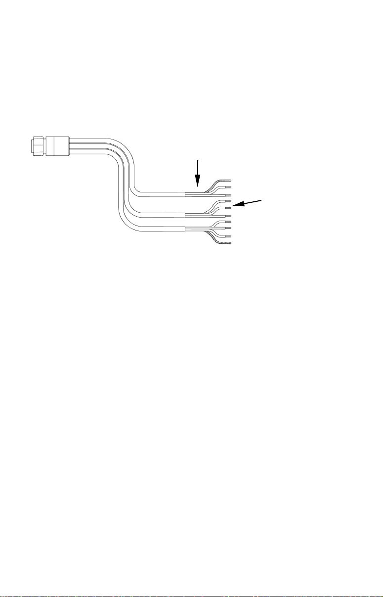
Power and Cable Connections
Your unit comes with a power/data cable that splits into three ends,
each with several exposed wires (shown in the following figure). The
end with 4 wires (blue, yellow, orange and shield) is a Data cable that
connects to a NMEA 0183 interface. The end with three wires (red,
black and shield) is a power cable that connects to a NMEA 2000 buss.
The thicker three-wire cable (red, black and white) is the Power Supply
for your unit (the white wire is unused).
Power Supply wires:
red, black and white
To unit
NMEA 2000 Power wires:
red, black and shield
NMEA 0183
Data Cable wires: blue,
yellow, orange and shield
The Power/Data cable for this unit.
Your unit will not use all of these wires. The following segments include
instructions for installing all the wires that you will use with this unit.
Caution:
All of the wires in the power/data cable have bare ends for easier installation. The bare ends on any unused wires could cause
an electrical short if left exposed. To prevent this, you should
cover the individual wire ends – either by capping them with
wire nuts or wrapping them with electrical tape. (You should cut
off the bare wire before taping off the ends.)
Powering a NMEA 2000 Buss – X135 and X136DF Only
(NMEA 2000 Power cable)
A NMEA 2000 buss must be connected to a power source to operate. If
you have a pre-existing NMEA 2000 installation, it may already be
connected to another power source. If your NMEA 2000 buss is already
powered, you can ignore the NMEA 2000 Power cable. Never attach
two power sources to a single NMEA 2000 buss.
If you do need to power your NMEA 2000 buss, attach the NMEA 2000
Power cable to your boat's battery just as indicated in the following
segment for connecting your unit's Power Supply cable. The NMEA
2000 Power cable's red wire should be attached (with provided 3-amp
fuse) to the boat battery's positive terminal, and the NMEA 2000 Power
cable's black and shield wires should both be attached to the battery's
negative terminal.
2
NOTE:
If your boat does not have a NMEA 2000 buss, do not connect the
NMEA 2000 wires!
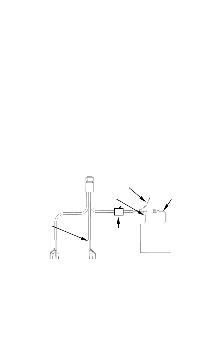
Powering Your Unit
(Power Supply cable – red and black wires)
The unit works from a 12-volt battery system. For the best results, attach the power cable directly to the battery. You can attach the power
cable to an accessory or power buss, however you may have problems
with electrical interference. Therefore, it's safer to go ahead and attach
the power cable directly to the battery.
If possible, keep the power cable away from other boat wiring, especially
the engine's wires. This will provide the best isolation from electrical
noise. If the cable is not long enough, splice #18 gauge wire onto it. The
power cable has two wires, red and black. Red is the positive lead, black
is negative or ground. (There is also a white wire to power an optional
external speaker for some units.) Make sure to attach the in-line fuse
holder to the red lead as close to the power source as possible.
For example, if you have to extend the power cable to the battery or
power buss, attach one end of the fuse holder directly to the battery or
power buss. This will protect both the unit and the power cable in the
event of a short. It uses a 3-amp fuse.
External speaker wire
To unit
To power a
NMEA 2000
buss, also
connect
NMEA 2000
Power cable
to the boat's
battery.
(not used by this unit)
Black wire
Optional power off
switch for saltwater installations
Red wire with
3 amp fuse
12 volt
battery
NMEA 0183
Data Cable
Power connections for this series of Lowrance sonars.
NMEA 2000 Power Cable
NOTE:
If you're powering a NMEA 2000 buss, you will attach both the
NMEA 2000 Power cable and the unit's Power Supply cable to the
boat's battery. To attach the NMEA 2000 Power cable, connect the
red wire to battery's + and black and shield wires to battery's –.
3
 Loading...