

Page 1

™
Pub. 988-0154-173
Setup and Installation of
NMEA 2000® Networks
General Information
The NMEA 2000 Network DeviceNet is the communication bus standard developed by the National Marine Electronics Association
(NMEA) for use in boats. Lowrance has introduced a line of products
that can communicate over a NMEA 2000 network, helping you get the
most out of this technology.
This instruction sheet will show how a NMEA 2000 network is created,
configured and installed.
Read the next few pages to become familiar with some of the following
terms: NMEA 2000 Network/LowranceNET, NMEA 2000 Bus/Network
Bus, Network Backbone, Network Nodes and Linear Architecture.
NMEA 2000® Network or LowranceNET™
A NMEA 2000 network is a communications link between two or more
devices that transfer NMEA 2000 information. LowranceNET is the
NMEA 2000 networking system developed by Lowrance Electronics. A
NMEA 2000 network functions like the phone wiring in a house. If, for
example, you pick up a phone in the living room you will be able to
hear the conversation someone is having on a phone in the bedroom.
In similar fashion, a NMEA 2000 network allows multiple display units
to receive data from a GPS antenna or multiple sonar units to receive
messages sent by a temperature sensor. A NMEA 2000 network gives
you the flexibility to view engine diagnostics and fuel level data on digital gauges or display units located anywhere on your boat.
If you have a Lowrance display unit with a LGC-3000 GPS module installed, you have a NMEA 2000 network. The connectors and cables
that came with your LGC-3000 function as a dedicated NMEA 2000
network, passing GPS data along the network to the GPS display unit.
This is a simple form of a NMEA 2000 network.
On the other end of the scale is a large network bus. You can easily expand a network bus by adding multiple NMEA 2000 devices, even adding the same type of device more than once.
The network could share information with a sonar-GPS combo unit
mounted in the dash, a sonar-only unit mounted at the stern and another display unit mounted on the bow. In that scenario, all three dis-
1
Page 2

play units attached to the bus would have access to information from
every sensor attached to the network. That is the advantage of a NMEA
2000 network.
WARNING:
The network MUST be installed in an area where it
WILL NOT be submerged in standing water during normal operation of your vessel.
NOTE:
We recommend applying dielectric grease to all NMEA 2000 backbone and device connections. This will prevent moisture from corroding the connector terminals. Before connecting a T connector to
another T connector or a NMEA 2000 device, apply a small amount
of dielectric grease on the pin connectors of both male and female
connectors.
Every display unit, gauge or sensor attached to the network can communicate with all other devices on the network. Location, speed and temperature, however, are not the only kinds of information that can be shared.
Fuel Remaining data along with engine information like oil pressure and
fuel efficiency are among a large number of data options that may be
shared on the network.
NOTE:
Full Sonar Chart returns CANNOT be transmitted on a NMEA 2000
network, because they take too much bandwidth for the network.
Every sonar display unit requires its own transducer. If, however,
you have a sonar display unit (with sonar bottom lock) connected to
the NMEA bus, it will share the digital depth with all display units
on the network.
NMEA 2000 Bus or Network Bus
Technically, any physical cable used to transfer network information is
a network bus, but in our documentation we use this term to refer to
the standard manufacturer installation appearing in new boats. This
network bus is an operational network cable, connected to a power supply and properly terminated, that will run the length of your boat. It
will provide access to network nodes at various locations on the boat.
2
Page 3
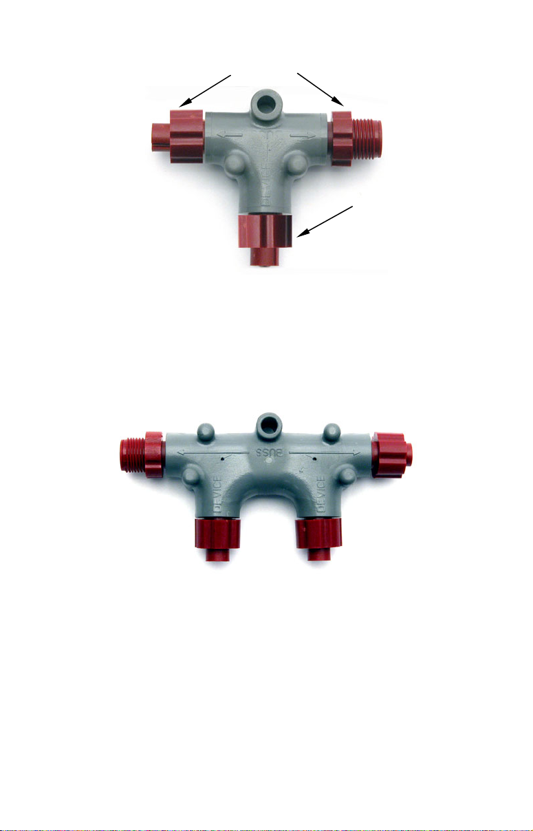
(
)
Connection for backbone
Sides of T
(Connection for devices)
Bottom of T
This T connector allows you to add a device to your NMEA 2000 bus
creating a network node.
Network Backbone and Network Nodes
A network bus backbone consists of network cabling, terminators and T
connectors. Network nodes are made by fitting T-shaped connectors into
the backbone (using the sockets on the sides) and attaching any network
device to the bottom of the T.
Double T connector
Staying with the previous phone wiring example, T connectors on the
backbone are the equivalent of phone jacks spread throughout a house.
To pick up a phone and be able to hear a conversation from another
phone in the house, both phones have to be connected to the main phone
line. In similar fashion, only sensors and display units plugged into the
NMEA network can share information. The network backbone is like the
phone wiring that runs throughout a home.
It connects the network nodes, allowing them to communicate across the
network. Connections found in the middle of the bus could have T connectors or backbone network cable plugged into one or both sides. Connec-
3
Page 4
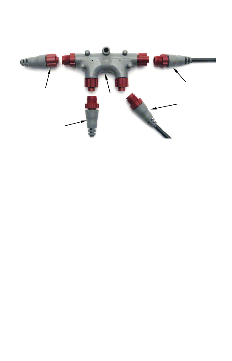
tions at the end of a network will have the backbone cable plugged into
one side and a terminator plugged into the other, as shown in the following figure.
Backbone cable
Terminator at
the end of the
backbone (bus)
Cap for unused
connector
Double T
connector
(to rest of bus)
Cable from
sensor or
display unit
NMEA 2000 network node located at the end of a NMEA 2000 backbone.
NOTE:
If you have a double T Connector on your network that is not attached to a device, you must cap the unused connector with a
NMEA 2000 cap. This will protect the pin connectors from corrosion. The NMEA 2000 cap looks like a terminator, but has "Cap"
stamped into the connector housing.
All T connectors on your network probably will be connected to a device.
If you want to add another node to a working network, add another T
connector. T connectors may be purchased from LEI (ordering information appears on the back page of this booklet). If you are adding a
Lowrance or LEI NMEA 2000 sensor, it will come with its own T connector.
Linear Architecture
NMEA 2000 networks are constructed using a linear pattern. It is important linear architecture is maintained when the network is modified or a
node is added to the network.
Linear architecture refers to way the network's nodes are connected to
the network backbone. Note that every T connector has two female sockets and one male socket. This means you could connect it in two different ways. Using linear construction, the T connectors will be connected
side by side, leaving the bottom of the T available for connection to a
display unit or NMEA 2000 device, like the "Correct installation" figure
on the next page. A network built following a linear construction is easier to maintain and expand.
4
Page 5
It also allows you to ensure the two terminators are at the ends of the
p
r
backbone. If your installation does not follow a linear architecture, the
network may not function.
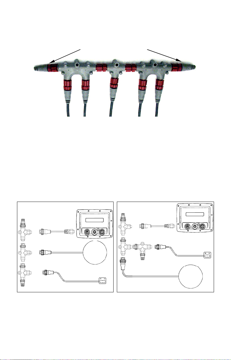
Backbone (Network bus)
This network bus has a cluster of single and double T connectors and is
terminated on both ends. It is connected to a display unit and four NMEA
2000 devices.
You could use the recommended installation, plugging the sensor or
display unit into the bottom of the T and the backbone cable into the
side of the T. You also could plug the sensor or display unit into the
side of the T and the backbone connection into the bottom of the T. The
sockets would allow you to make that connection, but you would lose
linear construction. Both installations are detailed in the following figures.
Correct installation
Sonar or GPS
display unit
EP-35
tem
LGC3000
senso
Incorrect installation
Sonar or GPS
display unit
EP-35
temp sensor
LGC3000
Two possible network designs. The design on the left maintains a linear
architecture while the one on the right does not. You should always
maintain linear architecture when building a NMEA 2000 network.
Both network designs in these images contain the same set of components. Both networks are terminated and all of the connectors are able
5
Page 6
to be connected to one another, but the installation on the left comes to
a clear end with terminators on each end of the backbone. The nonlinear installation on the right has no clear end, increasing the chance
of an installation error.
It also makes network expansion more difficult and could even prevent
the network from functioning.
Always maintain linear architecture when modifying your network.
Make sure display units or sensors are attached to the bottom of the T.
Attach the sides of the T to backbone extension cables, terminators or
other T connectors – nothing else. All network examples in this document show networks built with a linear architecture.
Adding a Network Node
You can add a node to any existing connection, anywhere along the network backbone. This connection could be between a T connector and a
terminator, between two T connectors, between a T connector and a
backbone extension cable or between two extension cables. Wherever you
want to add the new node, separate the sockets of the existing connection
and install the T connector between them.
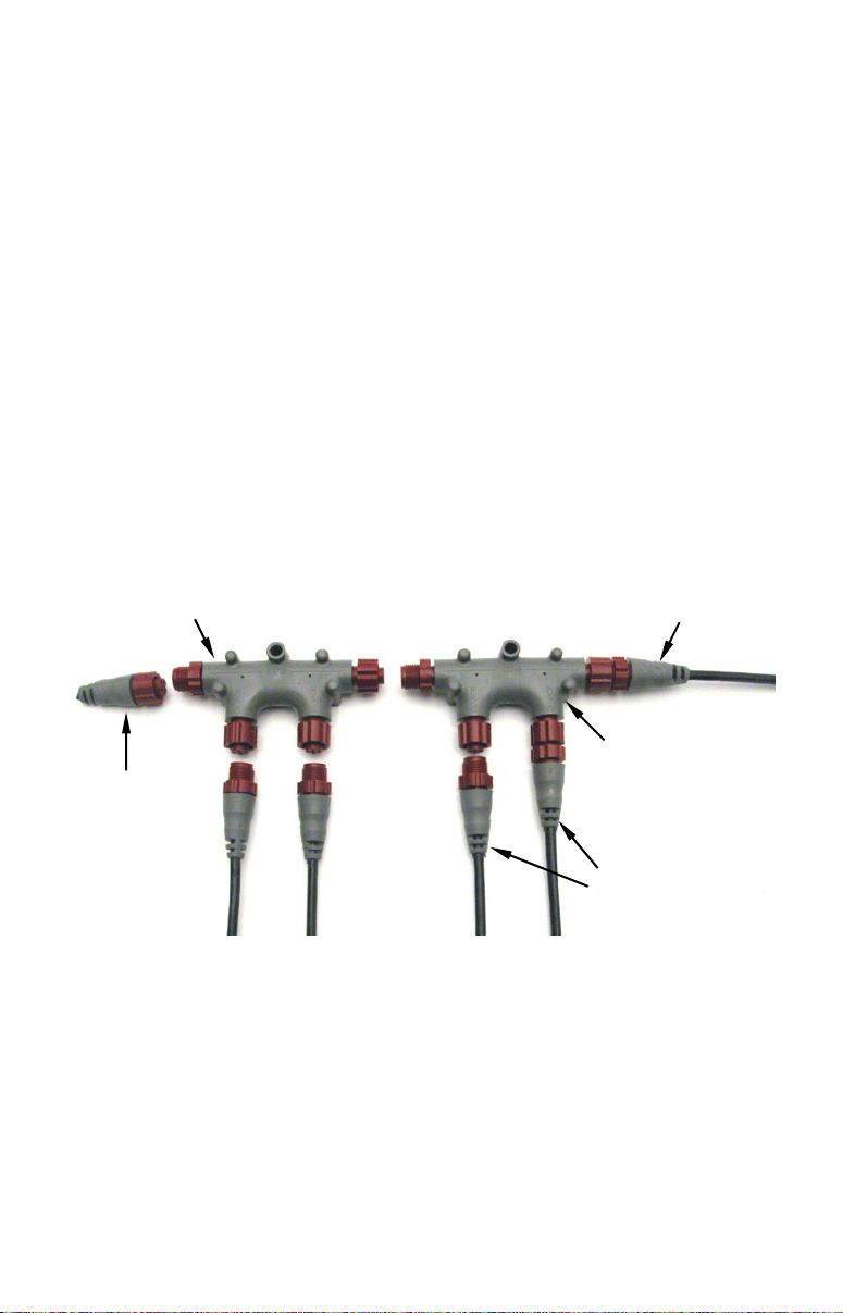
Use T-connector or double T connector to add
device to bus (maintaining linear architecture)
Backbone cable
to rest of bus
Existing network
Attach
terminator at
end of bus
In this example, a new device is added to the NMEA 2000 bus by install-
ing a T connector between a T connector and a terminator at the end of
the backbone (network bus).
node
Devices connect to
double T connector
If you want to add a node at the end of the backbone (network bus) remove the terminator from the last connector, like the figure above. Install the new T connector and attach the terminator to the side of the
connector.
6
Page 7

Adding an Extension Cable
LEI provides LowranceNET extension cables in various lengths, giving
you the flexibility to install T connectors at desired locations on your
boat. Every extension cable has a male connector on one end and a female connector on the other, allowing you to insert it anywhere on the
network where there is an existing connection.
You, for example, could have a cluster of T connectors at the bow of your
boat with a 15' extension cable attached to the last T on the cluster. You
could run the 15' extension cable to your boat's helm, where another cluster of T connectors could be installed. Just like the first cluster of T connectors, the last T connector on the cluster at the console could be connected to another extension cable running to the stern of the boat, where
another cluster of T connectors could be installed. To ensure communi-
cation, make sure your network backbone to less than 300 feet (100
meters) long.
LowranceNET Node Kit for a NMEA 2000 network. Includes a 2 foot
extension cable, T connector, 120-ohm male terminator and 120-ohm
female terminator.
You can also attach an extension cable between a device on the network
and its connection point at the bottom of the T connector. That would allow you to position the device right where you want it. You, however,
should never have more than 18' (about 6 meters) of cable between a device and its T connector.
Building a LowranceNET NMEA 2000 Network
In 2005, boat manufacturers (Original Equipment Manufacturers —
OEM) began installing NMEA 2000 networks as standard equipment
on new boats. If your boat does not have an OEM-installed NMEA 2000
network, you will have to install your own or take it to a qualified
NMEA 2000 technician to have one installed for you.
7
Page 8

Power Connections
Your unit comes with a power/data cable that splits into three
branches, each with several exposed wires.
The thicker two-wire cable (red and black) is the power supply for your
display unit. This cable has no label.
The branch with three wires (red, black and shield) is the power cable
for a NMEA 2000 network. It is labeled "NMEA 2000 POWER."
The branch with 5 wires (blue, yellow, orange, green and shield) is a
data cable, labeled "RS-232 COMM." It supports two serial communication ports. These allow your unit to exchange NMEA 0183 data with
another device, such as an autopilot, DSC marine radio or computer.
Display unit power wires:
red and black
To unit
NMEA 2000 power wires:
red, black and shield
Data cable wires: blue,
yellow, orange, green
The Power/Data cable for this unit.
and shield
NOTE:
There are two basic power connection options, which are shown in
the following two diagrams. Read the following instructions
carefully to determine which power connection applies to
your unit. Depending on your configuration, you may not use all of
these wires.
Caution:
All of the wires in the power/data cable have bare ends for easier installation. The bare ends on any unused wires could cause
an electrical short if left exposed. To prevent this, cover the individual wire ends – either by capping them with wire nuts, wrapping them with electrical tape or both. (You should cut off the
bare wire before taping off the ends.)
Powering Your Display Unit
The display unit works from a 12-volt DC battery system. Attach the
display power cable (with provided 3-amp fuse) to an accessory switch
or power bus. If this results in electrical interference, connect direct to
a battery but install an in-line switch on the cable.
8
Page 9

Caution:
We strongly recommend you shut off the power supply to the power
cable when the unit is not in use, especially in saltwater environments. When the unit is turned off, but still connected to a power
supply, electrolysis can occur in the power cable plug. This may result in corrosion of the plug body along with the electrical contacts
in the cable and the unit's power socket. Risk of electrolysis corrosion is even greater when the cable is unplugged from the unit, but
still connected to a power source.
We recommend you connect the power cable to the auxiliary power
switch included in most boat designs. If that results in electrical
interference, or if such a switch is not available, we recommend
connecting direct to the battery and installing an in-line switch.
This will let you shut off power to the power cable when the unit is
not in use. When you are not using the unit, you should always
shut off power to the power cable, especially when the power cable
is disconnected from the unit.
WARNING:
This product must be independently fused with the enclosed 3-amp fuse (or equivalent), even if you connect to
a fused accessory or power bus.
If a malfunction happens inside the unit, extensive damage can occur if the enclosed fuse is not used. As with all
electrical devices, this unit could be damaged to a point
it is unrepairable and could even cause harm to the user
when not properly fused.
Failure to use a 3-amp fuse will void your warranty.
If possible, keep the power cable away from other boat wiring, especially
the engine's wires. This will provide the best isolation from electrical
noise. If the cable is not long enough, splice #18 gauge wire onto it.
The display power cable has two wires, red and black. Red is the positive
(+) lead, black is negative (–) or ground. Make sure to attach the in-line
fuse holder to the red lead as close to the power source as possible.
If, for example, you have to extend the power cable to the power bus or
battery, attach one end of the fuse holder directly to the power bus or
battery. This will protect both the unit and the power cable in the event
of a short.
This unit has reverse polarity protection. No damage will occur if the
power wires are reversed. The unit, however, will not work until the
wires are attached correctly.
9
Page 10

Power Diagram A
p
Mandatory
network
power-off
switch
Shield
3-amp fuse
Black
Red
Black
12 volt DC
power source
Display Unit
Power Cable
Data Cable
To unit
NMEA 2000
Power Cable
3-amp fuse
Recommended
display unit
ower-off switch
Use this method if you are powering the display unit and a GPS mod-
ule or the display unit and a NMEA 2000 network.
The network and any NMEA 2000 devices, including the GPS
module, will not operate
unless the NMEA 2000 Power Cable is
connected to power. The NMEA 2000 power cable must be connected
to power even if your only NMEA 2000 device is the GPS module and it
is connected to the display unit's Network socket. (Never connect
multiple power sources to a NMEA 2000 network. If you have a
network that is already powered, see diagram B below.)
10
Page 11

Power Diagram B
To unit
Display Unit
Power Cable
All unused
Data or NMEA
2000 power
wires should
be capped
with wire nuts
and electrical
tape to prevent
Data Cable
Use this method if you are only powering your display unit and are not
powering a NMEA 2000 network or any NMEA 2000 accessory device,
NMEA 2000 Power Cable
Recommended
power off switch
including a GPS module.
Black wire
Red wire with
3-amp fuse
12 volt DC
power source
The method in diagram B is also used when your display unit is connected to a NMEA 2000 network that is already connected to power.
(Never connect multiple power sources to a NMEA 2000 network.)
Powering a NMEA 2000 Network Bus
A NMEA 2000 bus must be connected to a power source to operate.
NMEA 2000 devices draw their power from the network bus.
If you have a pre-existing NMEA 2000 network installation, it may already be connected to another power source. If you are not sure about a
network's power status, consult the boat manufacturer or dealer. If your
NMEA 2000 bus is already powered, you can ignore the NMEA 2000
Power cable and use the method shown in Power Diagram B above.
Never attach two power sources to a single NMEA 2000 bus.
If you need to power your NMEA 2000 bus, attach the NMEA 2000
Power cable to an accessory switch as indicated in power diagram A.
11
Page 12

The NMEA 2000 Power cable's red wire should be attached (with provided 3-amp fuse) to the positive (+) terminal. The NMEA 2000 Power
cable's black and shield wires should be attached to the negative (–)
terminal.
WARNING:
The NMEA 2000 network bus is always on, so it is constantly drawing power. You must connect NMEA power
to a switched power source so the network can be
turned off when not in use. Failure to connect NMEA
power to a power switch and/or failure to use a power
switch connected to NMEA power will drain your boat's
battery, which could prevent your boat from operating.
In addition to the three-branched power/data cable that comes with
Lowrance display units, Lowrance and LEI provide two other methods of
powering a NMEA 2000 bus. These include a "Power Terminator" and a
"Power Node." Many manufacturer-installed networks use one of these
alternate power sources. If your network already includes either of these
power sources DO NOT connect the NMEA 2000 power cable of any of
your GPS or sonar display units. Cap unused power wires with wire nuts
or electrical tape.
OEM factory installations typically use a Power Node similar to this to
supply power to the network bus. The red and black leads are con-
nected to a switched power source, allowing the user to turn off power
to the bus.
12
Page 13

WARNING!
If you connect multiple power sources to a NMEA 2000
network you could cause severe damage to the network,
network devices and your boat!
Terminators
A NMEA 2000 network needs to be terminated with two 120-ohm terminators, for it to work properly.
If your boat came with an NMEA 2000 bus installed, the terminators will
already be attached. The terminators provide resistance necessary for
devices to communicate along the network. This communication takes
the form of electrical pulses sent out by the device transmitting information. In order for the network to operate, you need 60-ohms of resistance to pull the network back to its recessive state after a signal is
sent, so the next pulse can be heard. Two 120-ohm terminators in parallel are used to create this resistance. Attach a 120 ohm terminator to
one end of the NMEA 2000 backbone. Attach the second terminator to
the other end of the backbone.
NOTE:
NEVER attach a terminator to a NMEA 2000 network bus that has
already been terminated.
Setting up a Network
Lowrance and LEI provide all the cables you will need to create a NMEA
2000 network. Lowrance provides T connectors and extension cables so
you can add devices along the backbone wherever you want. Once you
have a working network, every sensor added will come with its own T
connector for easy expansion.
Remember: The simplest NMEA 2000 network is a display unit with
the LGC-3000, one double-T connector and two 120 ohm terminators.
The diagram below details how to set up that type of network.
120-ohm
terminator
Double T
Connector
LGC-3000 and GPS display unit as an expandable NMEA 2000 network.
120-ohm
terminator
Extension cable
Network port
on GPS unit
LGC3000
13
Page 14

The diagram above has a double T connector with two 120-ohm terminators — one at each end of the connector. It is easy to expand this network
by removing a terminator from one end of the double T connector, then
inserting a new T connector or extension cable between the double T connector and terminator.
Adding a New Device to a Working Network Bus
Once your boat has a working NMEA 2000 bus, you no longer will have to
be concerned about power or terminators or configuring cables. Install
additional T connectors as described earlier and connect your Lowrance or
LEI devices to the network as described in the following paragraphs.
We will start with a simple network that includes a double T connector, a
GPS display unit, a LGC-3000, two T connectors and two 120-ohm terminators. If your boat came with a Lowrance NMEA 2000 network installed, its configuration will be similar to the diagram below, although it
probably will have additional devices attached. Now we want to add a
second display unit to the network. Adding a second display unit will give
you two units receiving GPS data from the installed LGC-3000.
The network will be set up exactly like the network we described earlier but
with an extra node. The extra extension cable and T connector may have
come packed with the second display unit, depending on the unit and unit
package assembly you purchased.
120-ohm
terminator
Network port
on GPS unit
First GPS display unit
Double T
Connector
Attach the Double T
connector directly to
the Single T connector or use an extension cable.
120-ohm
terminator
NMEA 2000 network with LGC-3000 connected to two GPS display units.
Extension cable
LGC3000
Second GPS display unit
Extension cable
The diagram below shows how to expand the network by adding an EP35 Temperature Sensor. The sonar-GPS display unit would receive the
GPS signal from the LGC-3000 and temperature information from the
temp sensor.
14
Page 15

120-ohm
terminator
Sonar-GPS
display unit
Attach all three T
connectors sideby-side, or insert
extension cables
between them.
120-ohm
terminator
Lowrance NMEA 2000 network with display unit,
GPS module and temp sensor.
Extension cable
LGC3000
EP-35
temp sensor
You also could connect a LGC-3000, a temp sensor and two sonar-GPS
display units to the network. To do that, follow the procedure for adding a network node covered earlier in the Adding a Network Node segment.
120-ohm
terminator
Attach all four T
connectors sideby-side, or insert
extension cables
between them.
Sonar-GPS
unit
Extension cable
LGC3000
EP-35
temp sensor
Sonar-GPS
unit
120-ohm
terminator
You can continue expanding your network by adding new network
nodes. The following figure shows a more extensive example of a
NMEA 2000 network. In addition to all the display units and sensors, it
includes two 120-ohm terminators and a total of seven network nodes.
You must keep the length of your network backbone to less than 300 feet
(100 meters).
Network with two sonar-GPS display units, a GPS module
and temp sensor.
15
Page 16

Compatibility
NMEA 2000 Sonar/GPS combo units purchased in 2005 had blue connectors and were packed with blue connector components, including a
Y cable and 60-ohm terminator. NMEA 2000 units and components
with blue connectors can be used with Lowrance's NMEA 2000 red
connector display units and components with the purchase of one of
four adapter cables.
The NMEA 2000 Red-to-Blue adapter cable will allow users to add red
connector devices to a blue connector network.
The adapter cables are two feet long and include:
NAC-FRD2FBL — adapter cable that allows you to connect red
connector devices to a blue connector network.
NAC-MRD2MBL — adapter cable that allows you to connect
blue connector devices to a red connector (DeviceNet) network.
NAC-FRD2MBL — adapter cable that will connect a red connec-
tor NMEA 2000 network backbone ending in a male connector
(DeviceNet) with a blue connector backbone ending with a female connector.
NAC-MRD2FBL — adapter cable for connecting a red connector
(DeviceNet) NMEA 2000 backbone ending with female connector
to a blue connector backbone ending with a male connector.
16
Page 17

The T connector with blue connectors (left). DeviceNet Micro-C con-
nector (right) used in some NMEA-2000 buses.
Some boats will come with a manufacturer-installed NMEA 2000 network that does not use red or blue LowranceNET connectors. Many of
these networks will use the DeviceNet Micro-C connector shown in the
image above.
Blue connector display units and components also can be used with DeviceNet Micro-C connectors with the purchase of a DeviceNet Micro-C to
Lowrance Male converter bus adapter cable.
To NMEA 2000
network port
Micro-C to Lowrance Male converter.
To Lowrance unit
or LEI accessory
With this adapter cable, you can connect the Micro-C plug (left end of
cable) to an available network connector on your boat's NMEA 2000 bus.
The Lowrance plug (right end of cable) connects to a Lowrance display
unit or NMEA 2000 sensor.
Micro-C connectors work with Lowrance red connector display units
and components, so no adapter cables are needed. If you are going to
add red connector components to a Micro-C network, follow the instructions and diagrams from this document.
17
Page 18

NMEA 0183
The NMEA 2000 communication standard is not a new concept. It was
developed to replace the old standard NMEA 0183. NMEA 0183 developed over a period of many years and changed dramatically during that
time. Development was so drastic some of the older NMEA 0183 devices
(NMEA 0183 ver. 1) are no longer compatible with NMEA 0183 devices
developed recently (NMEA 0183 ver. 3).
NMEA 2000 devices WILL NOT communicate with NMEA 0183
devices.
NOTE:
Some Lowrance display units may require software upgrades to
correctly show NMEA 2000 information. Log on to our website,
www.lowrance.com, to check for free software updates.
18
Page 19

Notes
19
Page 20

How to Obtain Service…
…in the USA:
Contact the Factory Customer Service Department. Call toll-free:
For Lowrance: 800-324-1356. For Eagle: 800-324-1354
8 a.m. to 5 p.m. Central Standard Time, M-F
Lowrance Electronics and Eagle Electronics may find it necessary to change or end
their shipping policies, regulations and special offers at any time. They reserve the
right to do so without notice.
…in Canada:
Contact the Factory Customer Service Department. Call toll-free:
800-661-3983
905-629-1614 (not toll-free)
8 a.m. to 5 p.m. Eastern Standard Time, M-F
…outside Canada and the USA:
Contact the dealer in the country where you purchased your unit. To locate a
dealer near you, see the instructions in paragraph number 1 below.
Accessory Ordering Information
LEI Extras™, Inc. is the accessory source for sonar and GPS products manufactured by Lowrance Electronics and Eagle Electronics. To order Lowrance or
Eagle accessories, please contact:
1) Your local marine dealer or consumer electronics store. To locate a Lowrance
dealer, visit the web site, www.lowrance.com, and look for the Dealer Locator.
To locate an Eagle dealer, visit the web site, www.eaglesonar.com, and look for
the Dealer Locator. Or, consult your telephone directory for listings.
2) U.S. customers: LEI Extras Inc., PO Box 129, Catoosa, OK 74015-0129
Call toll free in the U.S., 800-324-0045, 8 a.m. to 5 p.m. Central Stan-
dard Time, M-F, or visit our web site www.lei-extras.com.
3) Canadian customers: Lowrance/Eagle Canada, 919 Matheson Blvd. E. Mississauga, Ontario L4W2R7 or fax 905-629-3118.
Call toll free in Canada, 800-661-3983, or dial 905 629-1614 (not toll free), 8
a.m. to 5 p.m. Eastern Standard Time, M-F.
For Lowrance® and Eagle® Products
Pub. 988-0154-173 © Copyright 2006
All Rights Reserved
Printed in USA 112006 LEI
20
 Loading...