

Pub. 988-0170-011
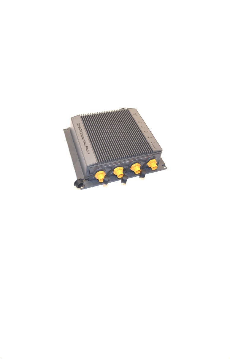
NEP-1
Navico Expansion Port
This document will show you how to install a Navico Expansion Port
(NEP-1). The NEP-1 has five Ethernet ports used to share a variety of
information — including sonar and radar data — with multiple display
units, depending on the capability of the display unit.
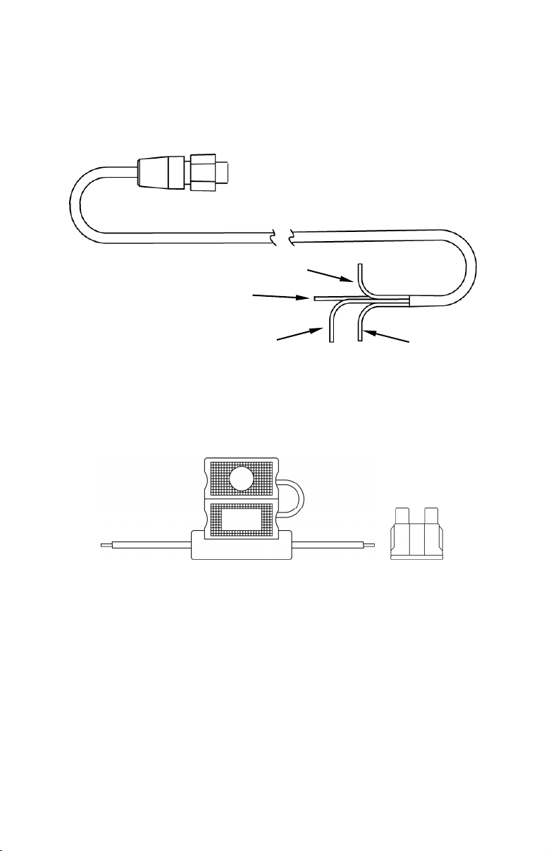
The NEP-1 comes packed with a fuse, an inline fuse holder and a 6'
power cable.
Navico Expansion Port (NEP-1).
Tools and Supplies
Required tools include: drill, drill bits, Phillips screwdriver. For thruhull installations, you also will need a 5/16" (8mm) wrench.
Required supplies differ depending on how you are going to install the
NEP-1 (thru-hull or self-tapping). None of the required supplies are
included with your NEP-1.
Thru-hull installation:
• No. 6 (3.5mm) stainless steel machine screws (4)
• No. 6 (3.5mm) stainless steel screw lock-washer nuts (4)
• 5/32" (4mm) drill bit
Self-tapping installation:
• No. 6 (3.5mm) self-tapping, stainless steel screws (4)
• No. 6 (3.5mm) lock washers (4)
• 7/64" (2.5mm) drill bit
1
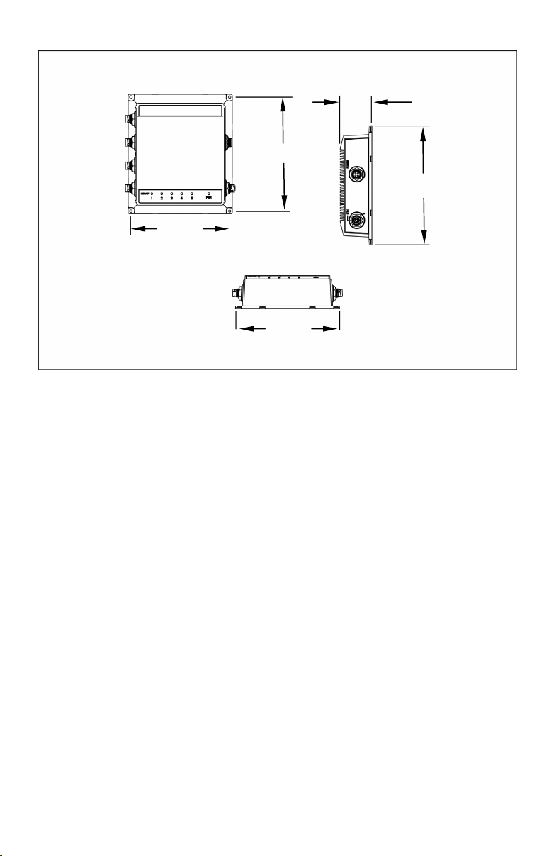
)
2.26in (57.5mm
)
7.76in (197.0mm)
8.27in (210.0mm
6.89in
(175.0mm)
7.40in
(188.0mm)
Installation
1. Select a location for NEP-1 installation that will allow desired
display units to connect to the NEP-1 without kinking, stressing or
tangling Ethernet cables.
NOTE:
Install the NEP-1 module and power cable at least 3 feet
away from your VHF radio antenna to prevent interference.
2. Place the NEP-1 against the installation surface. Mark pilot hole
locations through the ears at each corner of the module.
Caution:
You should read the entire installation section before drilling
any holes in your vessel!
3. Remove the NEP-1 from the installation surface. Using the pilot hole
marks as a guide, drill the pilot holes. If you are using a thru-hull
installation, you will need a 5/32" (4mm) drill bit. For self-tapping
installations, use a 7/64" (2.5mm) drill bit.
4. Align the NEP-1 with the pilot holes and install the screws.
If you are using a thru-hull installation, you will need No. 6 stainless
steel machine screws and stainless steel lock-washer nuts. For selftapping installations, use No. 6 self-tapping, stainless steel screws with
lock-washers.
2
Power Connections
Y
The NEP-1 has four wires; red (+), black (–), yellow and blue. The red
wire is positive, the black wire is the ground and the yellow wire
connects to a switch. The blue wire will not be used. Cap the end of the
blue wire with a wire nut or electrical tape.
ellow wire to
switchbox
Blue wire
not used
Black wire (–)
to battery (–)
Red wire (+) to
inline fuse to
battery (+)
1. Insert the supplied fuse into the fuse holder. Attach the red positive
wire (+) to the fuse holder.
2. Connect the wire on the other end of the fuse holder to a wire
connected to the positive battery terminal (+).
Fuse holder Fuse
3. Attach the black ground wire (–) to the negative battery terminal (–).
4. Connect the yellow wire to a switchbox. Refer to your switchbox
instructions for more information.
NOTE:
If you connect the yellow wire directly to the battery (always-on
configuration), you will have to disconnect the NEP-1 from the
battery when your boat is not in use; otherwise it will run down the
battery.
3

5. Plug the power cable into the NEP-1 power connector.
6. Connect an Ethernet cable (not supplied) to the desired display unit.
Plug the other end of the cable into the desired NEP-1 Ethernet port.
Repeat Step 5 for each display unit you want to connect to the NEP-1.
WARNING
When Ethernet ports are not in use, cover them with the
supplied dustcaps to prevent corrosion.
4

Notes
5

Notes
6

NAVICO
FULL ONE-YEAR WARRANTY
"We," "our," or "us" refers to NAVICO, the manufacturer of this product. "You" or "your"
refers to the first person who purchases this product as a consumer item for personal,
family or household use.
We warrant this product against defects or malfunctions in materials and workmanship,
and against failure to conform to this product's written specifications, all for one (1) year
from the date of original purchase by you. WE MAKE NO OTHER EXPRESS
WARRANTY OR REPRESENTATION OF ANY KIND WHATSOEVER CONCERNING
THIS PRODUCT. Your remedies under this warranty will be available so long as you can
show in a reasonable manner that any defect or malfunction in materials or
workmanship, or any non-conformity with the product's written specifications, occurred
within one year from the date of your original purchase, which must be substantiated by
a dated sales receipt or sales slip. Any such defect, malfunction, or non-conformity which
occurs within one year from your original purchase date will either be repaired without
charge or be replaced with a new product identical or reasonably equivalent to this
product, at our option, within a reasonable time after our receipt of the product. If such
defect, malfunction, or non-conformity remains after a reasonable number of attempts to
repair by us, you may elect to obtain without charge a replacement of the product or a
refund for the product. THIS REPAIR, OR REPLACEMENT OR REFUND (AS JUST
DESCRIBED) IS THE EXCLUSIVE REMEDY AVAILABLE TO YOU AGAINST US FOR
ANY DEFECT, MALFUNCTION, OR NON-CONFORMITY CONCERNING THE
PRODUCT OR FOR ANY LOSS OR DAMAGE RESULTING FROM ANY OTHER
CAUSE WHATSOEVER. WE WILL NOT UNDER ANY CIRCUMSTANCES BE LIABLE
TO ANYONE FOR ANY SPECIAL, CONSEQUENTIAL, INCIDENTAL, OR OTHER
INDIRECT DAMAGE OF ANY KIND.
Some states do not allow the exclusion or limitation of incidental or consequential
damages, so the above limitations or exclusions may not apply to you.
This warranty does NOT apply in the following circumstances: (1) when the product has
been serviced or repaired by anyone other than us; (2) when the product has been
connected, installed, combined, altered, adjusted, or handled in a manner other than
according to the instructions furnished with the product; (3) when any serial number has
been effaced, altered, or removed; or (4) when any defect, problem, loss, or damage has
resulted from any accident, misuse, negligence, or carelessness, or from any failure to
provide reasonable and necessary maintenance in accordance with the instructions of the
owner's manual for the product.
We reserve the right to make changes or improvements in our products from time to time
without incurring the obligation to install such improvements or changes on equipment or
items previously manufactured.
This warranty gives you specific legal rights and you may also have other rights which
may vary from state to state.
REMINDER: You must retain the sales slip or sales receipt proving the date of your
original purchase in case warranty service is ever required.
NAVICO, INC.
12000 E. SKELLY DRIVE, TULSA, OK 74128
(800) 324-1356
7

How to Obtain Service…
…in the USA:
Contact the Factory Customer Service Department. Call toll-free:
For Lowrance: 800-324-1356. For Eagle: 800-324-1354
8 a.m. to 5 p.m. Central Standard Time, M-F
Lowrance Electronics and Eagle Electronics may find it necessary to change or end
their shipping policies, regulations and special offers at any time. They reserve the
right to do so without notice.
…in Canada:
Contact the Factory Customer Service Department. Call toll-free:
800-661-3983
905-629-1614 (not toll-free)
8 a.m. to 5 p.m. Eastern Standard Time, M-F
…outside Canada and the USA:
Contact the dealer in the country where you purchased your unit. To locate a
dealer near you, see the instructions in paragraph number 1 below.
Accessory Ordering Information
LEI Extras™, Inc. is the accessory source for sonar and GPS products
manufactured by Lowrance Electronics and Eagle Electronics. To order
Lowrance or Eagle accessories, please contact:
1) Your local marine dealer or consumer electronics store. To locate a Lowrance
dealer, visit the web site, www.lowrance.com, and look for the Dealer Locator.
To locate an Eagle dealer, visit the web site, www.eaglesonar.com, and look for
the Dealer Locator. Or, consult your telephone directory for listings.
2) U.S. customers: LEI Extras Inc., PO Box 129, Catoosa, OK 74015-0129
Call toll free in the U.S., 800-324-0045, 8 a.m. to 5 p.m. Central
Standard Time, M-F, or visit our web site www.lei-extras.com.
3) Canadian customers: Lowrance/Eagle Canada, 919 Matheson Blvd. E.
Mississauga, Ontario L4W2R7 or fax 905-629-3118.
Call toll free in Canada, 800-661-3983, or dial 905 629-1614 (not toll free), 8
a.m. to 5 p.m. Eastern Standard Time, M-F.
Pub. 988-0170-011 © Copyright 2008
All Rights Reserved
Printed in USA 012508 Navico
8
 Loading...