

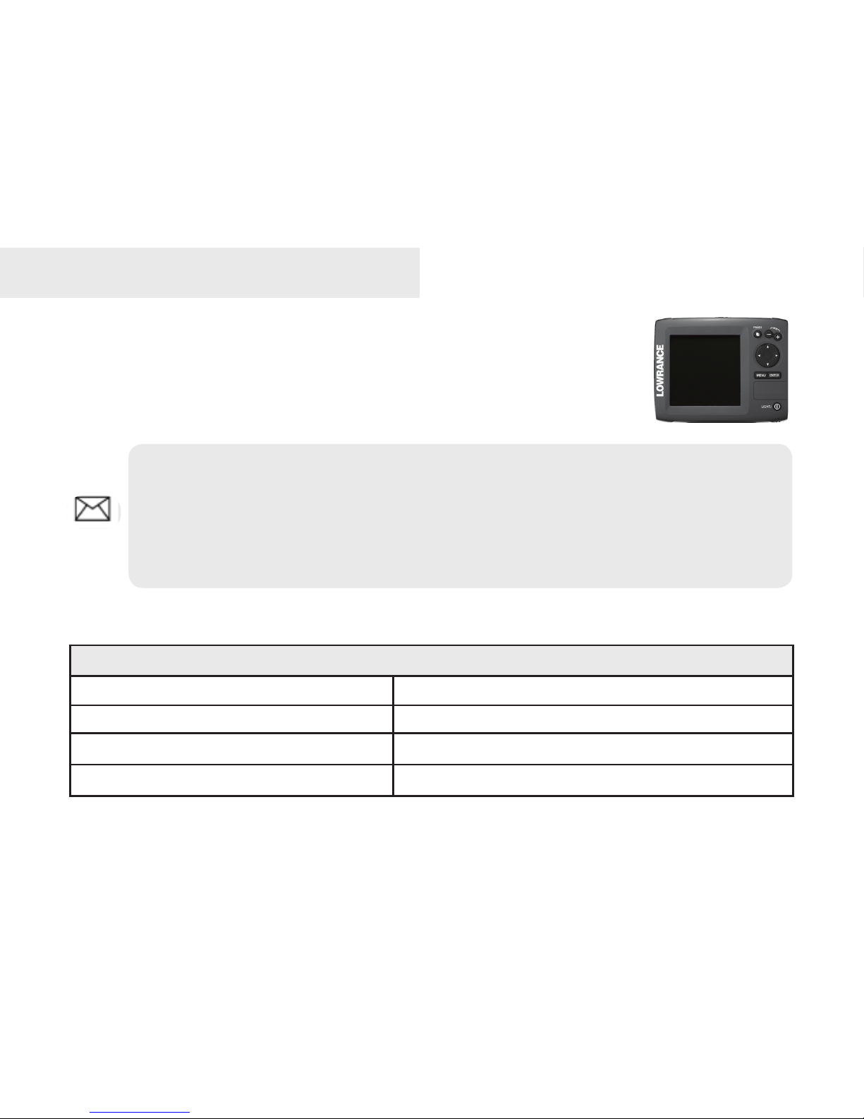
Lowrance Mark-5x DSI, Mark 5x, Mark 5x Pro, Elite 5x Installation And Operation Manual

Mark 5x, Mark 5x Pro & Elite 5x sonar
Installation & Operation manual

Copyright © 2009 Navico
All rights reserved.
No part of this manual may be copied, reproduced, republished, transmitted or distributed for any purpose,
without prior written consent of Navico. Any unauthorized commercial distribution of this manual is strictly
prohibited.
Navico may nd it necessary to change or end our policies, regulations and special offers at any time.
We reserve the right to do so without notice. All features and specications subject to change without
notice.
Lowrance® and Navico® are registered trademarks of Navico.
Visit our website:
www.lowrance.com
Navico
12000 E. Skelly Dr.
Tulsa, OK USA 74128-2486

1
Table of Contents
Installation ..................................2
Basic Operation .......................13
Pages .............................................14
Sonar ............................................. .14
Split Zoom ..................................... .14
Split Frequency.............................. .14
Split Flasher................................... .14
Working with menus ....................... 16
Exiting menus ................................ .17
Selecting a Fishing Mode ............... 17
Restoring Defaults ......................... .18
Standby mode ................................18
Advanced Mode.............................. 18
Sonar Operation ......................19
Viewing Sonar History ................... 19
Sensitivity ...................................... .20
Auto Sensitivity .............................. .20
Depth Range ..................................21
Frequency...................................... .21
Sonar Options menu...................... .21
Overlay Data................................... 23
Settings Menu ..........................24
System............................................ 24
Language ...................................... .24
About ............................................. .24
Surface Clutter .....................................25
Keel Offset ......................................26
Temperature calibration ................. .26
Alarms ........................................... 27
Units ..............................................27
Simulator ....................................... 27
Specications ..........................28
2
Mark and Elite Series Installation
This document covers the installation of the transducer and display unit
installation, which includes connecting the unit to power and installing the
unit on the bracket mount.
Transducer Installation
One piece bracket (Recommended Tools and Supplies — not included)
Drill Marine grade above-or-below waterline sealant
1” (25mm) or 5/8” (15mm) drill bit Marine grade epoxy (Shoot-thru-hull install only)
#29 (0.136”) (3mm) drill bit Zip ties (trolling motor mount)
Phillips (Slotted-head) screwdriver TMB-S bracket kit (Skimmer trolling motor mount)
NOTE: Make sure you read all the installation instructions before drilling holes
in your vessel. Check the transducer cable and power wires to make sure they will
reach the desired mounting location for the display unit. If they will not reach,
you either will have to select a different mounting location for the display unit, or
extend the transducer cable and /or power wires.
Installation
3
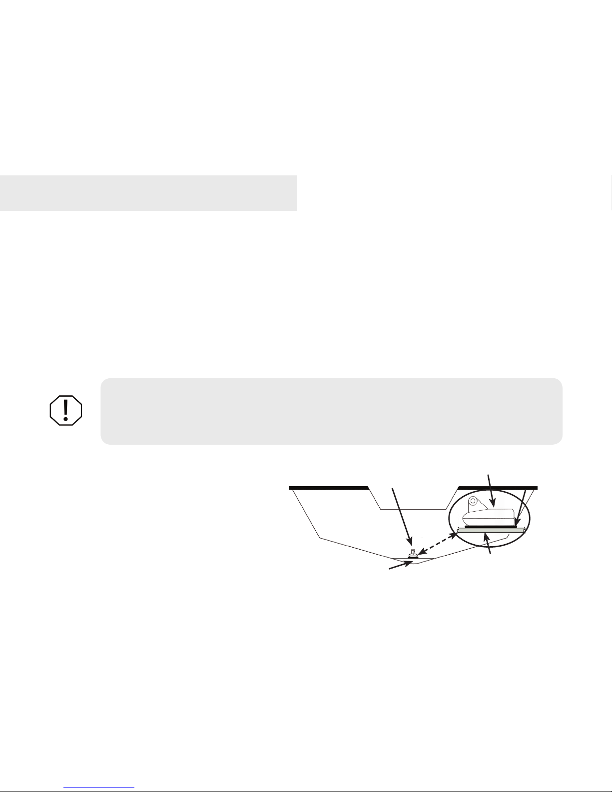
A. Select a transducer location
To function properly the Skimmer transducer must be in the
water at all times and in a location that has a smooth ow of
water when the boat is moving.
If the transducer is not placed in a smooth ow of water,
interference caused by bubbles and turbulence may cause
the product to not perform properly. The unit also could lose
bottom signal when the boat is on plane. Install transducer
at least 1’ (.3m) away from the engine’s lower unit.
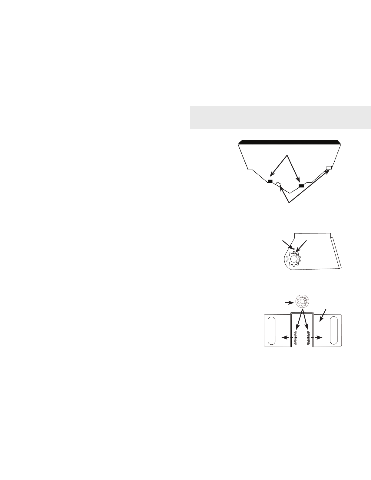
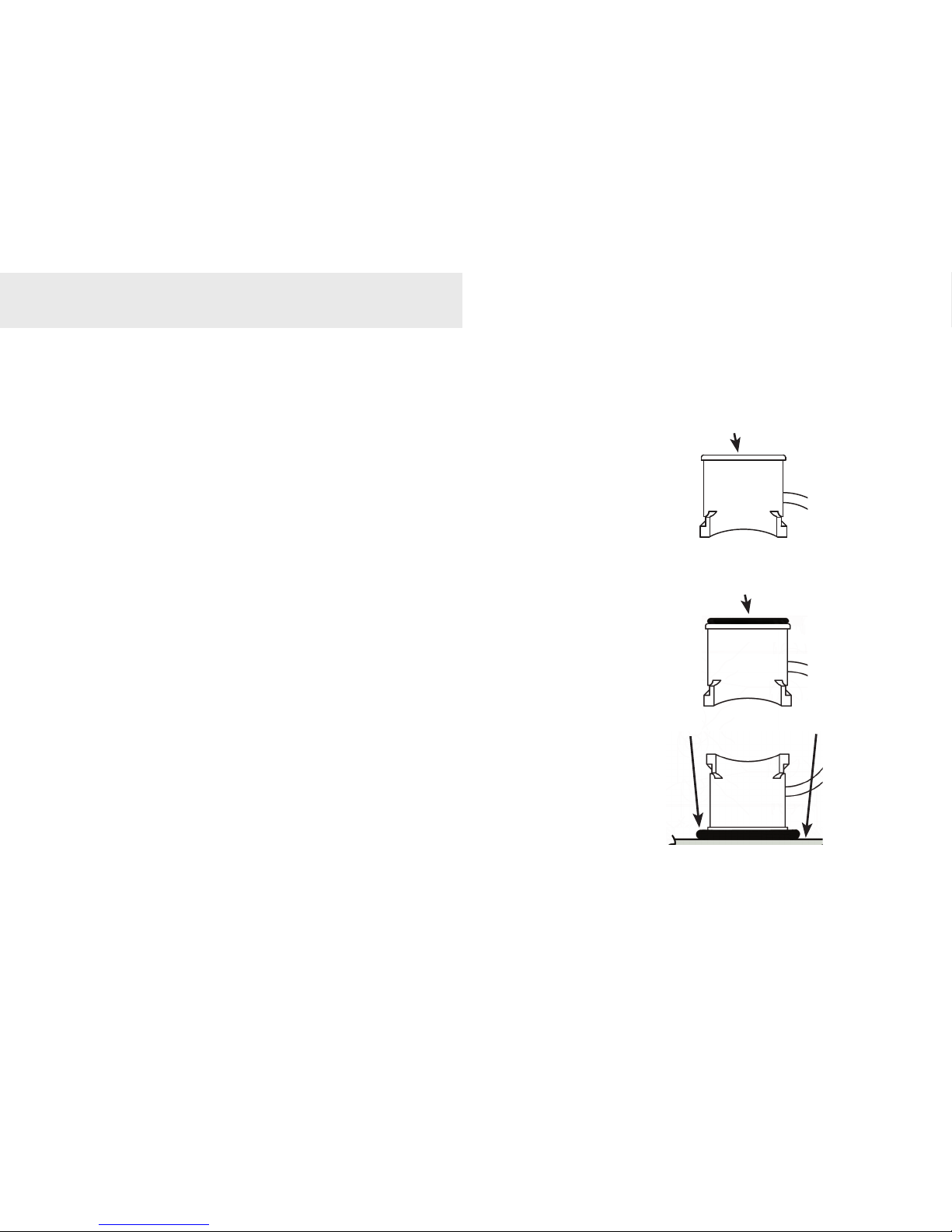
B. Aligning Ratchets on Transducer bracket
You will use the ratchets to ensure the transducer is installed parallel to
the ground.
Insert the ratchets in the bracket with the letter “A” 1.
aligned with the dot stamped on the outside of the
transducer bracket.
Slide the transducer into the bracket and temporarily 2.
slide the bolt through the transducer bracket.
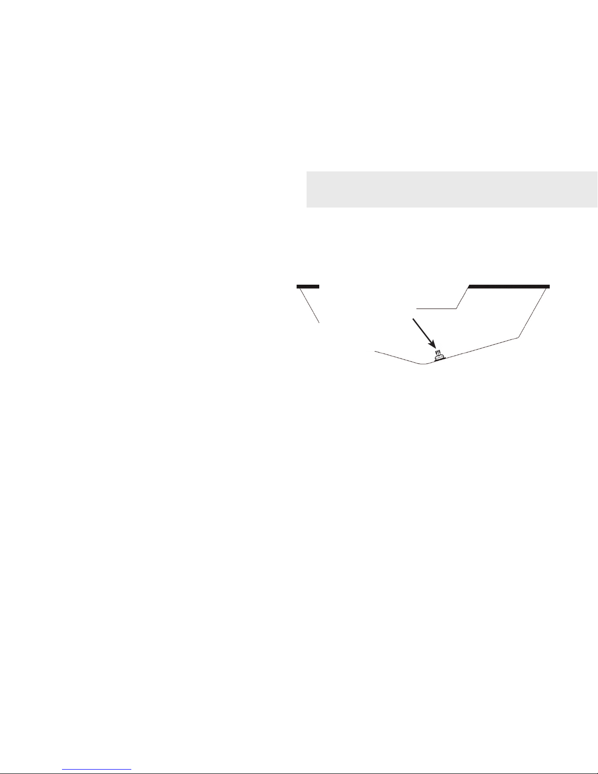
Good locations
Poor locations
Align dot and letter
"A".
dot
A
Ratchet
Bracket
Installation
4
Hold the transducer assembly against the transom. Look at 3.
the transducer from the side. If it is parallel to the ground,
then the “A” position is correct.
If the transducer can not be adjusted so its face is parallel 4.
to the ground, remove the transducer and ratchets from
the bracket. Reinsert the ratchets into the bracket, this
time with the letter “B” aligned with the dot stamped in the
bracket. Reassemble the transducer and bracket and place
it against the transom.
Check to see if the transducer will adjust so its face is parallel with the ground. 5.
Repeat this process until the transducer can be adjusted so its face is parallel
with the ground.
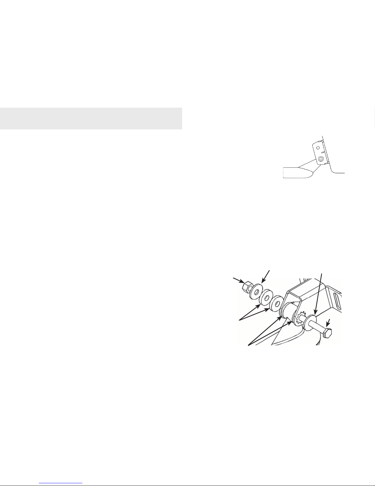
C. Assembling the bracket
After determining the correct position for
the ratchets, loosely assemble the transducer
and bracket assembly.
Lock nut
Metal washer
Rubber washers
Ratchets
Metal washer
Bolt
Installation
Place the
transducer and
bracket against
the transom.
5
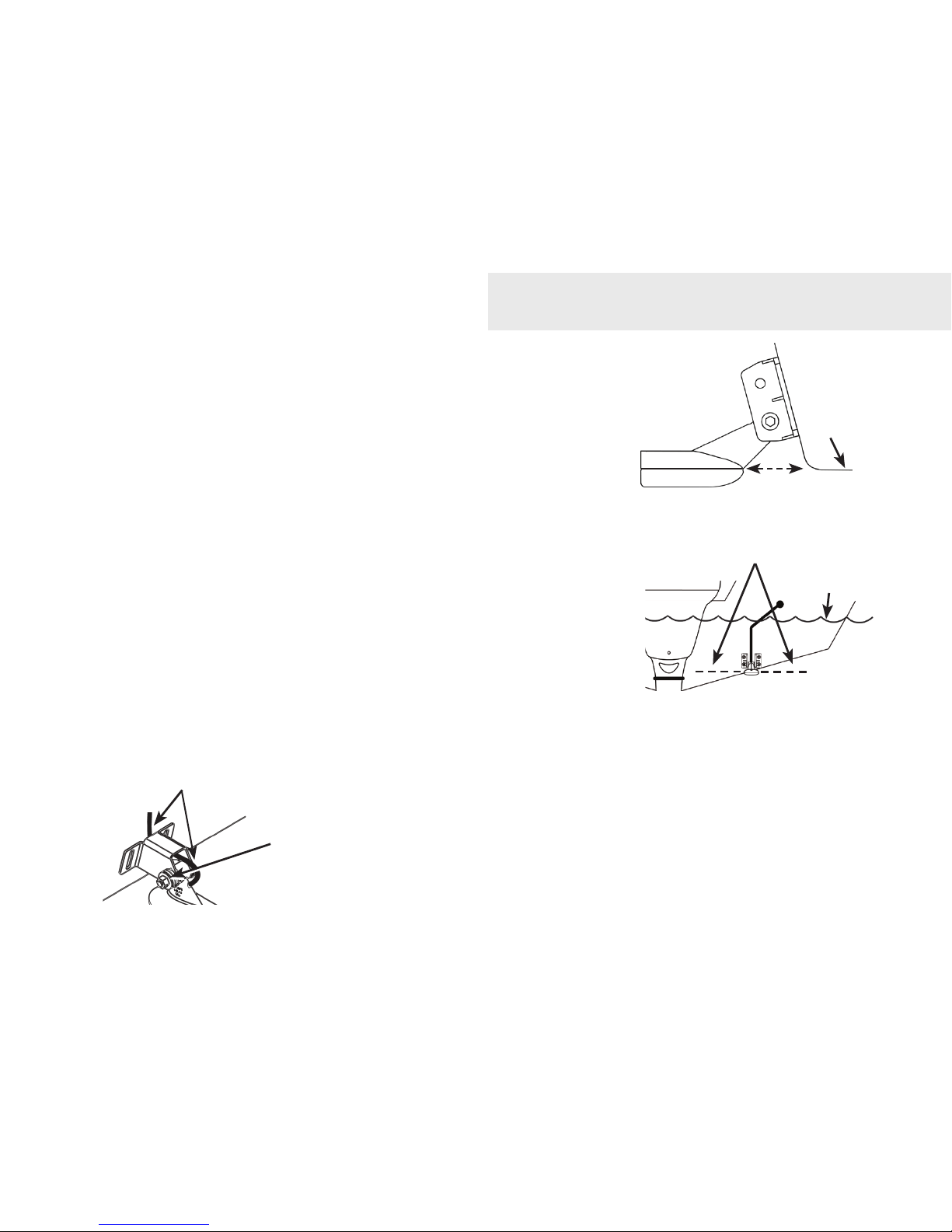
D. Attaching Transducer to Transom
Adjust the transducer so its face is parallel with the 1.
ground and its center line is even with the bottom
of the boat hull.
Hold the transducer and bracket assembly against 2.
the transom. When the transducer and bracket
are properly aligned mark its position on the hull.
Drill the mounting holes for the transducer bracket. 3.
Use a #29 bit (for the #10 screws).
Routing cables
When mounting your transducer, make sure to leave some slack in the cable near the transducer.
If you need to drill a hole in the transom to pass the connector
through, the hole size will depend on the connector on the end of the
transducer’s cable.
Installation
The transducer centerline must
be even with the boat hull. Its face
should be parallel to the ground.
Transom
Bottom
of hull
Waterline
Do not overtighten the lock nut; otherwise the transducer
will not be able to kick up if it strikes an object
Run cable over the bolt
and through the bracket.
6
E. Make a test run
After the transducer is installed make a test run to ensure the transducer is installed properly.
Use the slots in the transducer mounting bracket to loosen the screws and slide the transducer
up or down, if adjustments are necessary.
Shoot-thru-hull Skimmer & Pod transducer installation
Before attempting any installation on boats with otation material sandwiched within the hull,
consult the boat manufacturer.
In a shoot-thru-hull installation the
transducer is epoxied to the inside of the
boat hull.
A transducer can not shoot through wood
or metal hulls. Wood and metal hulls
require either a transom mount or thruhull installation.
WARNING: Do not remove material from the inner hull. Careless grinding on
the hull could damage hull integrity. Contact the boat dealer or manufacturer to
conrm hull specications
.
Transducer epoxied to hull
Epoxy
Transducer
Hull
Keel pad
Installation
7
For shoot-thru-hull applications many boat hulls have a at keel pad that offers a good transducer
mounting surface.
Make sure the Skimmer transducer is oriented so the nose of the transducer is facing the bow
(front) of the boat. If the transducer has a
built in temp sensor, it will only show the
temperature of the hull, not the water temp.
Before you epoxy the transducer to the hull,
make sure the area is clean, dry and free of
oil or grease.
The surface of the hull must be at so the entire transducer face is in contact with the hull. Also,
make sure the cable is long enough to reach the sonar unit.
To use shoot-thru-hull installation:
Sand the inside surface of the hull, where the transducer is to be epoxied, and 1.
the face of the transducer. Sand the hull until it is smooth to the touch. The
sanded area should be about 1-1/2 times the diameter of the transducer.
2. After sanding, clean the hull and the face of the transducer with an alcohol
wipe to remove any dust.
On vee hulls
try to place the
transducer where
the dead rise is
10° or less.
Installation
8
Apply a thin layer of epoxy (about 1/16” or 1.5 3.
mm) on the face of the transducer and the
sanded area on the hull. Be careful when
mounting a transducer inside a boat hull.
Once epoxied into position, the transducer
can not be removed.
Press the transducer into the epoxy, turning 4.
it to force out any air bubbles from under the
transducer face. Make sure there are no air
pockets in the epoxy layers.
Stop pressing when it bottoms out on the hull. 5.
Apply pressure to hold the transducer in place
while the epoxy sets. Be careful not to move
the transducer while the epoxy is setting. Allow
the epoxy to set before moving the boat.
When nished, the face of the transducer should 6.
be parallel with the hull with a minimum amount
of epoxy between the hull and transducer.
Sand transducer face
and mounting location
Apply epoxy to transducer
face and mounting location.
Epoxy transducer to hull.
HullEpoxy
Installation
9
Trolling motor Skimmer and Pod Installation
The TMB-S trolling motor bracket (Part No. 51-45) is an optional accessory and is available
through LEI Extras at www.lei-extras.com. The TMB-S bracket is used to attach a one-piece
bracket skimmer transducer to a trolling
motor.
The Pod transducer does not need a TMB-S
trolling motor bracket to be installed on a
trolling motor. It only needs a hose clamp
(adjustable strap).
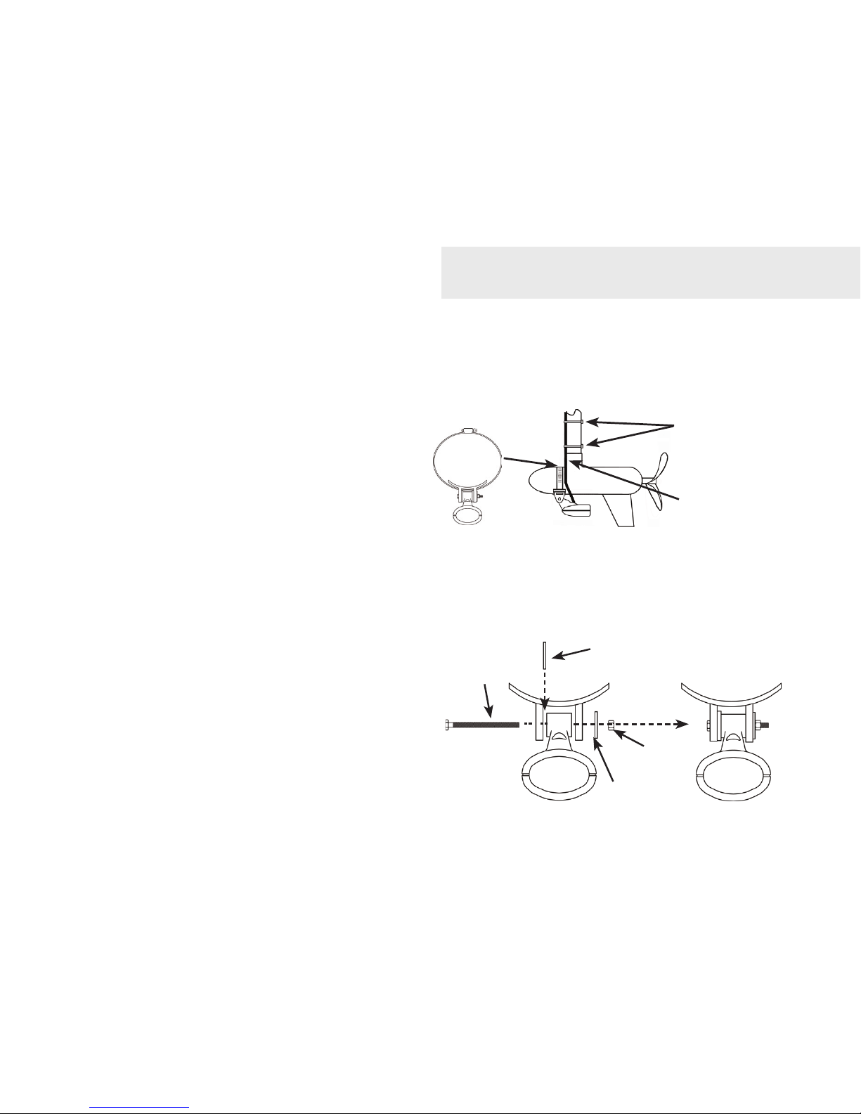
Installing transducer on trolling motor:
Using the components supplied with the TMB-S bracket attach the skimmer 1.
transducer to the bracket as shown
in the diagram.
Slide the adjustable strap (hose 2.
clamp) through the plastic bracket
on the skimmer transducer or
through the Pod transducer slots
and then slip the strap around the
trolling motor.
Flat washer
Lock
nut
Bolt
Internal tooth
washer
Plastic bracket
Adjustable strap
Plastic ties (not
included)
Move transducer
cable to back
side of shaft
Installation
 Loading...