

Elite 5X DSI, Mark 5X DSI, Elite 4X DSI & Mark 4X DSI
Installation & Operation
Operation manual
manual

Copyright © 2011 Navico
All rights reserved.
Lowrance® and Navico® are registered trademarks of Navico.
Navico may nd it necessary to change or end our policies, regulations and special oers at any time. We reserve
the right to do so without notice. All features and specications subject to change without notice.
Visit our website:
www.lowrance.com

Contenidos
Introducción ..................................... 2
Funcionamiento básico .................. 3
Asistente de conguración ......................3
Paginas....................................................3
Acceso al Menú de ajustes......................3
Funcionamiento de los menús.................4
Standby mode .........................................5
Restablecer ajustes de fábrica ................ 5
Página de DSI .........................................6
Páginas ............................................. 6
Frecuencia dividida..................................6
Zoom dividido .......................................... 7
Datos superpuestos.................................7
Funcionamiento de la DSI ............... 9
Uso de DSI ..............................................9
Trackback ...............................................9
Menú DSI.................................................9
Ajustar ...................................................10
Escala .................................................... 10
DSI interpretación.......................... 13
Ajustes............................................ 15
Menú de ajustes .................................... 15
Sistema..................................................15
Sonda ..................................................16
Alarmas ................................................18
Specications ................................ 25
1
Introduction
Introduction
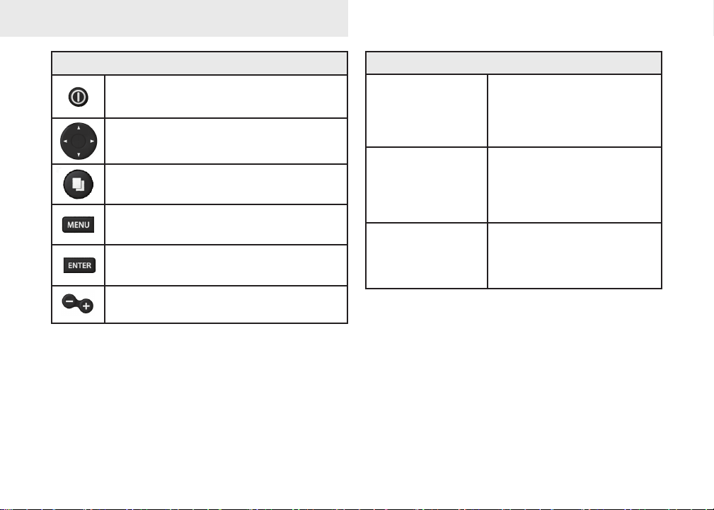
Unit Controls
LIGHT/POWER: controls backlight
level and turns unit on/off
KEYPAD: controls cursor & selects
items on menus
PAGES: allows you to select a page to
view
MENU: opens settings, context and
page menus
ENTER: nalizes menu selections;
save waypoint at cursor position
ZOOM Keys: used to zoom in/zoom
out
Getting Started
Turn unit on/off
Adjusting
the backlight
Muting Audio
To turn on/off the unit,
press and hold the LIGHT/
POWER key for three
seconds.
This unit has
levels. Press the LIGHT/
POWER key to switch
backlight levels.
Select Mute Audio from
the System menu and
press ENTER.
10 backlight
2
Basic Operation
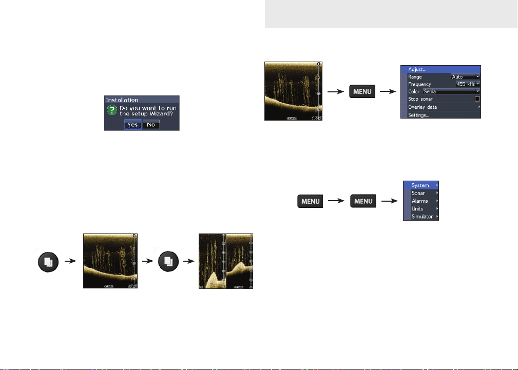
Setup wizard
The Setup wizard will appear when the unit is
turned on for the rst time. To choose your own
settings, do not run the setup wizard.
To restart the Setup wizard, restore defaults.
Pages
This unit has three pages: DSI, Split frequency and
Split zoom.
DSI menu
DSI page
DSI menu
Accessing the Settings menu
Settings menu
3
Basic Operation
Basic Operation
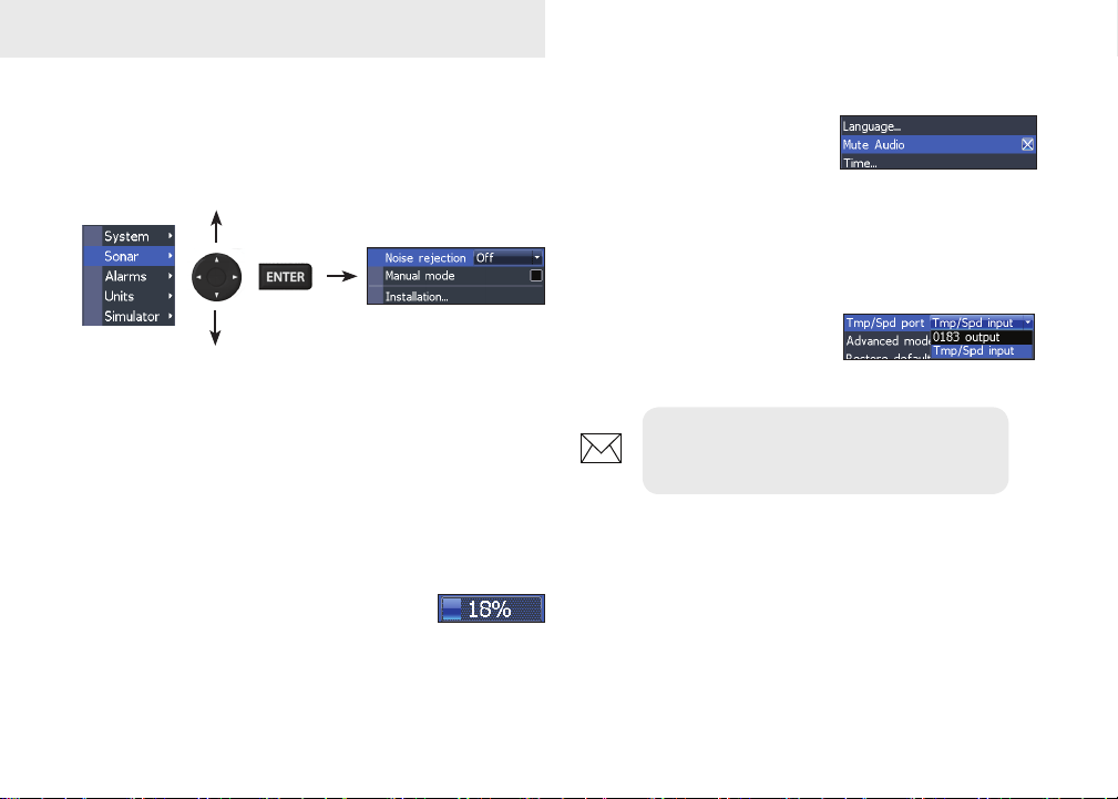
Accessing menu items
The keypad and ENTER key are used to select
menu items and open submenus. Use the keypad
to highlight the desired item and press ENTER.
Working with menus
There are several menu types used to make
adjustments to options and settings, including
scrollbars, on/o features and dropdown menus.
Scrollbars
Select the scrollbar and press the
keypad left (decrease) or right (increase).
On/Off features
Select an on/o menu item
and press ENTER to turn
it on/o.
Dropdown menus
After accessing the dropdown menu, press the
keypad up/down to select
the desired item and press
Enter.
NOTE: Press the MENU key to Exit
menus.
4
Basic Operation
Dialogs
Dialogs are used for user input or for presenting information to the user.
Depending on the type of information or entry, dierent methods are used to conrm, cancel
or close the dialog.
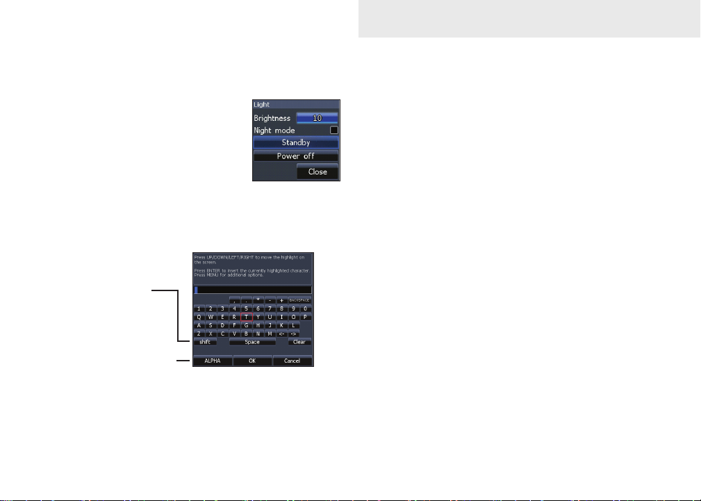
Entering text
Switches letters
to uppercase/
lowercase
Switches
keyboard between
Alpha and
QWERTY layout
To input text:
1. Use the keypad to select the desired
character and press ENTER.
2. Repeat Step 1 for each character.
3. When entry is completed, highlight OK
and press ENTER.
Cursor
The cursor is used to select review sonar history.
Press MENU and select Exit cursor mode to clear
the cursor.
5
Basic Operation
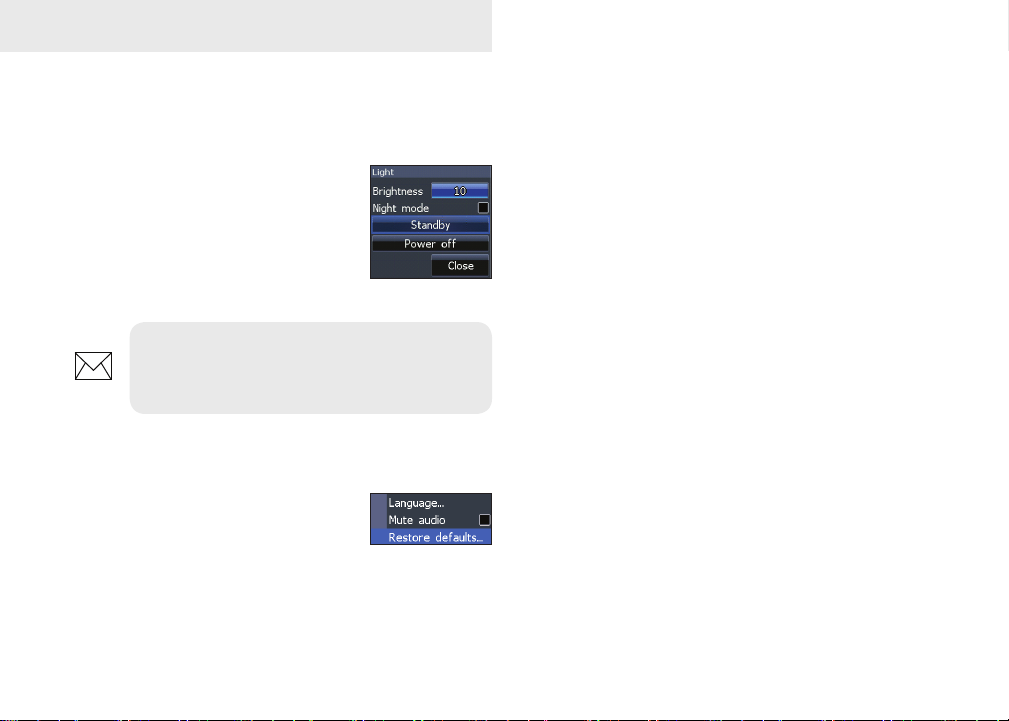
Standby mode
Lowers power consumption by turning o sonar
and the display.
Press the PWR/Light key to access the Backlight dialog. Select
Standby and press Enter.
Press any key to resume normal
operation.
NOTE: Leaving your unit in Standby
mode when your boat is not is use will run
down your battery.
Restore defaults
Resets unit options and settings
to defaults.
Adjusting the display
You can make adjustments to the display using
Contrast and Color settings. Both are covered in
the DSI section.
6

Pages
Pages
DSI Page
DSI Page
Displays the water column moving from right to
left on your unit’s screen.
DSI Split Frequency page
Split Frequency
Displays both transducer frequencies at the same
time. 800 kHz provides the best resolution, while
455 kHz has greater depth coverage.
7

Pages
DSI Split Zoom
Split Zoom
Allows you to zoom in for a closer look without losing your view of the water column.
Overlay Data
Allows you to select data (water temperature,
depth, etc) to be displayed on top of the DSI screen.
You can also turn on/o the display of congured
overlay data using the Show setting.
Overlay data
Show
Enables/disables the display of overlay data, allowing you to remove overlay data from the screen
without deleting the selected overlay data conguration.
8

Pages
Congure
Used to select and customize overlay data for display on the DSI screen.
To select overlay data:
1. From a DSI page, press MENU.
2. Select Overlay data and press ENTER.
3. Select Congure and press ENTER.
4. Press Menu and select Add. Press
ENTER.
5. Select the desired data from the Con-
gure Items to show screen. Press ENTER.
6. Press MENU and select Return to
overlays.
7. Press MENU, select Done Conguring
and press ENTER.
Customizing Overlay Data
Access the Overlay Data conguration menu to
make adjustments to the size and/or location of
overlay data on the display.
Press Menu from the Congure Item Locations and
Sizes screen to access the menu.
9

DSI
Using DSI
DSI history bar
Trackback
You can review your sonar history by pressing the
keypad to the left until the screen starts to move
in reverse and the sonar history bar appears at the
bottom of the screen.
Move the sonar history bar all the way to the right
to resume normal sonar scrolling, or press MENU
and select Exit cursor mode.
DSI menu
Press Menu from any DSI page to view the DSI
menu.
Stop sonar:
pauses the
sonar screen
10

DSI
Adjust
Accesses the Contrast adjustment
scrollbar, allowing you to adjust
contrast settings.
Contrast
Adjusts the brightness ratio between light and dark
areas on the screen, making it easier to distinguish
suspended objects from the background.
Contrast set
to 40
Contrast set
to 60
Contrast set
to 80
DSI units do not have a Sensitivity setting like traditional sonar units. Contrast functions as the sensitivity setting for DSI units.
Range
Selects the deepest range shown on the
display. Range settings display the section of the water column from the water
surface to the selected depth range.
Custom Range — Upper and Lower Limits
Used to select the upper limit and lower limit of
a section of the water column. That allows you to
view a section of the water column that does not
include the water surface.
Upper and lower limits must be at least 6.5 ft (2m)
apart.
11

DSI
NOTE: When using a custom range, you
may not receive any digital depth readings, or you may recieve incorrect depth
information.
Frequency
Controls the transducer frequency
used by the unit. 800 kHz oers the
best resolution, while 455 kHz has
greater depth coverage.
Color
Used to change the unit’s color palette. The Color setting
allows you to select a palette
best suited for your shing
conditions.
The White background palette works well for suspended targets. Purple is useful for viewing structure detail and determining bottom hardness.
Sepia is best for looking at bottom detail. Mono-
chrome uinits only support Grayscale and Reverse
Grayscale settings.
Surface Clarity
Surface Clarity reduces surface clutter by decreasing the sensitivity of the receiver near the surface.
Surface Clarity
set to Low.
Stop Sonar
Pauses the sonar chart, allowing you to get a better
look at suspended targets and structure.
Surface Clarity
set to High.
12

Overlay Data
Allows you to select data (water temperature,
depth, etc) to be displayed on top of the DSI screen.
Overlay data
Overlay data setup is covered in the Pages section.
Settings
Accesses the settings menu.
DSI
13

DSI Interpretation
Bridge
piling
Baitball
Pipes
Baitsh on
the move
14

DSI Interpretation
Fish
Thermocline
Structure
Structure
Trees
Fish
15

Settings
Settings
Settings Menu
Accesses installation and conguration settings for
your unit.
Settings
menu
System
Adjusts unit settings like language, mute audio
and advanced mode.
Turns on/off
unit audio
System menu
Displays software informa-
tion
16

Settings
Set Language
Selects the language used on
menus and text boxes.
Mute Audio
Turns on/o unit audio, like key beeps, alarm
sounds, etc.
Restore Defaults
Switches the unit back to default
settings.
About
Displays software information about this unit. Before attempting a software update, you can check
the version of software your unit is using by accessing the About screen.
Lowrance periodically updates unit software to
add features and improve functionality. To see the
latest available software version go to www.lowrance.com.
Sonar
Used to make adjustments to Sonar options and
settings.
Sonar Settings Menu
Restricts unit’s digital depth search
capability
17

Settings
Noise Rejection
Uses advanced signal processing to monitor the effects noise (boat pumps, water conditions, engine
ignitiion systems, etc.) has on your display, and
then lters out the undesired signals.
Manual Mode
Restricts digital depth capability, so the unit will
only send sonar signals to the selected depth
range. That allows the display to continue smooth
scrolling if the bottom depth is out of transducer
range.
WARNING: Manual mode should only be
used by advanced sonar users.
When the unit is in manual mode, you may not receive any depth readings, or you may recieve incorrect depth information.
Installation
Provides access to Keel Oset and Temp Calibration
settings.
Installation menu
Keel Offset
All transducers measure water depth from the
transducer to the bottom. As a result, water depth
readings do not account for the distance from the
transducer to the keel or from the transducer to the
water surface.
18

Transducer
Keel Offset (-3.5 feet)
Before setting keel oset, measure the distance
from the transducer to the lowest part of the keel.
If, for example, the keel is 3.5 feet below the transducer, it will be input as –3.5 feet.
Keel
Settings
Alarms
Enables Shallow alarm and allows you to select the
alarm threshold.
The Shallow alarm sounds an alarm when your vessel enters water shallower than the selected shallow threshold.
Units
Temperature calibration
Calibrates readings from the transducer temperature sensor with data from a known temperature
source to ensure the accuracy of temperature information.
Reset water distance
Reset Water Distance to zero.
Allows you to select the unit of measure used by your unit.
Simulator
Used to simulate on the water activity.
19

Specications
Elite 5x DSI & Mark 5X DSI
General
Case Size
Weight
Display
Backlight Cold cathode uorescent lamp (10 levels)
Transmit Power 4000W PTP; 500W RMS
Power
Requirement
Voltage Input 10 to 17V
Current drain
Fuse type
5.4” H (134mm) x 6.8” W (174mm); 6” H (152mm)
with bracket
Mark 5x: 1.35lbs (613kgs)
Elite 5x: 1.68lbs (.763kgs)
Elite: (5” diagonal) Enhanced Solar MAX™
480x480 256 color TFT LCD
Mark: (5” diagonal) 480x480 monochrome
Power
12 Volts DC
Elite 5x: at 13.5V (630mA)
Mark 5x: at 13.5V (320mA)
3-amp Automotive (not supplied)
DSI Sonar
Max depth
Transducer
Frequency
Max speed
Transducer DSI (Downscan) transducer
Transducer cable 20ft (6m)
250 ft (61m)
455/800kHz
50 mph (80 kph)
2-8 mph (3-12 kph) optimal for imaging

Specications
Elite 4x DSI & Mark 4X DSI
General
Case Size
Display
Backlight White LED (10 levels)
Transmit Power 2800W PTP; 350W RMS
Power
Requirement
Voltage Input 10 to 17V
Current drain at 13.5V (200mA)
Fuse type
5.6” H (144mm) x 3.7” W (94.3mm); 6.4” H (164mm)
with bracket
Elite 4: (3.5” diagonal) 320x240 (256 color) TFT
LCD
Mark 4: (3.5” diagonal) 320x240 monochrome
TFT LCD
Power
12V
3-amp Automotive (not supplied)
DSI Sonar
Max depth
Transducer
Frequency
Max speed
Transducer DSI (Downscan) transducer
Transducer cable 20ft (6m)
200 ft (76m)
455/800kHz
50 mph (80 kph)
2-8 mph (3-12 kph) optimal for imaging

Index
A
About 17
Adjusting contrast 11
Alarms 19
C
Color 12
Contrast 11
Cursor 5
Custom Range 11
D
Dialogs 5
Dropdown menus 4
DSI menu 3, 10
DSI Page 7
E
Entering text 5
Exit menus 4
F
Frequency 12
I
Installation menu 18
K
Keel Oset 18
L
Language 17
M
Manual Mode 18
Menus 4
Exit 4
Mute Audio 17
N
Noise Rejection 18
O
On/O features 4
Overlay Data 8, 13
Congure 9
Customizing 9
Show 8
R
Range 11
Reset water distance 19
Restore defaults 6
Restore Defaults 17
S
Scrollbars 4
Settings Menu 16
Setup wizard 3
Simulator 19
Software updates 17
Sonar Installation 18
Sonar settings 17
Split Frequency 7
Split Zoom 8
Standby mode 6
Stop Sonar 12
Surface Clarity 12
System settings 16
T
Temperature calibration
19
Trackback 10
U
Units 19
Upper and Lower Limits
11
W
Working with menus 4
22

How to Obtain Service… …in the USA:
Contact the Factory Customer Service Department. Call toll-free:
800-324-1356
8 a.m. to 5 p.m. Central Standard Time, M-F
Navico may nd it necessary to change or end shipping policies, regulations and special oers at any time. They reserve the right to
do so without notice.
…in Canada:
Contact the Factory Customer Service Department. Call toll-free:
800-661-3983
905-629-1614 (not toll-free)
8 a.m. to 5 p.m. Eastern Standard Time, M-F
…outside Canada and the USA:
Contact the dealer in the country where you purchased your unit. To locate a dealer near you, see the instructions in
paragraph number 1 below.
Accessory Ordering Information
LEI Extras is the accessory source for sonar and GPS products manufactured by Lowrance Electronics. To order
Lowrance accessories, please contact:
1) Your local marine dealer or consumer electronics store. To locate a Lowrance dealer, visit the web site, www.lowrance.com, and look for the Dealer Locator; or, consult your telephone directory for listings.
2) U.S. customers visit our web site www.lei-extras.com.
3) Canadian customers: Lowrance Canada, 919 Matheson Blvd. E. Mississauga, Ontario L4W2R7 or fax 905-629-3118.
Call toll free in Canada, 800-661-3983, or dial 905 629-1614 (not toll free), 8 a.m. to 5 p.m. Eastern Standard Time, M-F.

www.lowrance.com
*988-10149-001*
Visit our website:
© Copyright 2011
All Rights Reserved
Navico Holding AS
 Loading...