

Lowrance LVR850 User Manual
www.lowrance.com
Pub. 988-0158-001
LVR-850
LVR-850
DSC VHF Marine Radio
Installation and Operation
Instructions

Copyright © 2005 Lowrance Electronics, Inc.
All rights reserved.
Lowrance
®
is a registered trademark of Lowrance Electronics, Inc.
No part of this manual may be copied, reproduced, republished,
transmitted or distributed for any purpose, without prior written
consent of Lowrance. Any unauthorized commercial distribution
of this manual is strictly prohibited.
Lowrance Electronics may find it necessary to change or end our
policies, regulations, and special offers at any time. We reserve the
right to do so without notice. All features and specifications subject to
change without notice. All screens in this manual are simulated.
For free owner's manuals and the most current information on
this product, its operation and accessories,
visit our web site:
www.lowrance.com
Lowrance Electronics Inc.
12000 E. Skelly Dr.
Tulsa, OK USA 74128-2486
Printed in USA.

Table of Contents
Section 1: Installation .............................................................. 1
Introduction .................................................................................. 1
Powering Your Radio ................................................................ 1
Auxiliary Wires ......................................................................... 1
Bracket Installation.................................................................. 2
Antenna ......................................................................................... 3
How to Make a Distress Call........................................................ 4
Section 2: Basic Radio Operation .......................................... 5
Using the Keypad ......................................................................... 5
Power/Volume ........................................................................... 6
Squelch ...................................................................................... 6
H/L (High/Low) ......................................................................... 6
WX (Weather)............................................................................ 6
16/9 (Priority Channel) ............................................................. 6
SCN (Scan) ................................................................................ 6
MEM (Memory) ......................................................................... 7
CALL ......................................................................................... 7
DISTRESS.................................................................................7
Arrow Keys................................................................................ 7
PTT (Press to Talk)................................................................... 7
DSC Calling vs. non-DSC Calling ................................................ 7
What is a DSC call? .................................................................. 7
How DSC works ........................................................................ 8
Simplex or Duplex..................................................................... 8
MMSI (Maritime Mobile Service Identity) .................................. 8
MMSI Setup .............................................................................. 9
Choosing a Channel .................................................................... 10
Making a Call.............................................................................. 10
Receiving a Call .......................................................................... 11
Section 3: Advanced Operation............................................13
Calls......................................................................................... 13
Transmission........................................................................... 13
AllShips Call........................................................................ 13
Directory Call ...................................................................... 14
Distress Call ........................................................................ 14
Last Call .............................................................................. 16
New Call .............................................................................. 16
Reception ................................................................................. 18
AllShips Call........................................................................ 18
Distress Call ........................................................................ 18
Geographic Call................................................................... 18
Individual Call .................................................................... 19
i

Channels.................................................................................. 19
Channel Bank ......................................................................... 19
Directory..................................................................................20
Storing/Editing MMSI Data ............................................... 20
DSC Monitor ........................................................................... 21
GPS Operation ........................................................................ 22
H/L ........................................................................................... 22
Memory Operation .................................................................. 22
Position Send/Request ............................................................ 23
Transmission ....................................................................... 23
Reception ............................................................................. 24
Priority Channel (16/9) ........................................................... 25
PTT (Push To Talk)................................................................. 25
Scan ......................................................................................... 25
Weather (Wx) ..........................................................................27
Frequency Charts & Usage ...................................................28
FCC Radio License and MMSI Number Information
In U.S. waters, vessels which are not required to carry radio equipment
are not required to have an FCC (Federal Communications Commission) ship station license for a VHF marine radio.
However, any vessel required to carry a marine radio on an international voyage, carrying a HF single side band radio telephone or marine
satellite terminal must have an FCC license.
License application forms for ship and land stations can be downloaded
free from the FCC web site at this address:
You may also order copies of these forms by calling the FCC Forms Distribution Center at 1-800-418-3676.
At this time, the FCC does not require recreational boaters to have a
ship radio station call sign. The U.S. Coast Guard recommends using
the boat's registration number and state.
The BoatU.S. MMSI Program has been certified by both the Federal
Communications Commission (FCC) and the U.S. Coast Guard to assign MMSI numbers to vessels with DSC capable radios. To obtain and
register your free MMSI number, the Coast Guard recommends logging
onto
http://www.boatus.com/mmsi/ and following the instructions.
ii
www.fcc.gov/formpage.html.

FCC Digital Device Compliance
This device complies with Part 15 of the U.S. Federal Communications Commission (FCC) Rules. Operation is subject to the following two conditions: (1) this device may not cause harmful interference, and (2) this device must accept any interference received, including interference that may cause undesired operation.
Changes or modifications not expressly approved by the manufacturer could void the user's authority to operate the equipment.
Note:
This equipment has been tested and found to comply with the
limits for a Class B digital device, pursuant to Part 15 of the
FCC Rules. These limits are designed to provide reasonable protection against harmful interference in a residential installation.
This equipment generates, uses and can radiate radio frequency
energy and, if not installed and used in accordance with the instructions, may cause harmful interference to radio communications. However, there is no guarantee that interference will not
occur in a particular installation. If this equipment does cause
harmful interference to radio or television reception, which can
be determined by turning the equipment off and on, the user is
encouraged to try to correct the interference by one or more of
the following measures:
• Reorient or relocate the receiving antenna.
• Increase the separation between the equipment and receiver.
• Connect the equipment into an outlet on a circuit different from
that to which the receiver is connected.
• Consult the factory customer service department for help.
iii

FCC Radio Frequency
Compliance Requirements and Warnings
When operating your marine radio transceiver, you should know that
the antenna radiates radio frequency (RF) energy. This radio was designed to meet the FCC’s rules and regulations for the maximum permissible exposure to radio frequency energy. This design was tested
and found to be compliant with the strict requirements established by
the FCC.
DO NOT operate the radio without a proper antenna attached, because
this may damage the radio and may also cause you to exceed FCC RF
exposure limits. Antenna types suited for this radio are described in the
installation section.
DO NOT transmit for more than 50% of the total radio use time.
Transmitting more than 50% of the time can cause FCC RF exposure
compliance requirements to be exceeded. The radio is transmitting
when the “TX indicator” is displayed on the screen. You can cause the
radio to transmit by pressing the "PTT" (Push To Talk) switch.
IMPORTANT: The antenna(s) used for this transmitter must be installed to provide a separation distance of at least 91 cm (37 inches)
from all persons (including passengers). The antenna(s) must not exceed an antenna gain of 3 decibels (dB) and must not be co-located or
operating in conjunction with any other antenna or transmitter.
iv

Section 1: Installation
Introduction
Thank you for purchasing the Lowrance LVR 850 DSC VHF Radio. We
know you’re anxious to try it out, but first, let us explain how this
manual can help you get the most out of your new radio.
We have designed this book so you don’t have to read the whole thing
from front to back to find the information you want. At the start of each
segment, we’ll tell you what content is coming up next. If it’s a concept
you're already familiar with, we’ll show you where to find the next important topic.
We lead off the manual with proper Distress Call procedures on page 4.
We put it at the front of the book to make it easy to find in case of an
emergency.
The first section covers LVR-850 installation and specifications.
The second section, Basic Radio Operation, goes over some basic functions of the radio and includes instructions on how to set up your MMSI
(Maritime Mobile Service Identity) number. You can't make a call
without it! To jump to MMSI setup, flip to page 8. To acquire a
free MMSI number, see the web address on the bottom of page
ii.
The third section, Advanced Radio Operation, offers more detailed information about the radio's features. The section will touch on all aspects of the radio's functionality, providing clear and complete explanations via a convenient alphabetical layout.
Let’s get started!
Powering Your Radio
(Power Supply cable – red and black wires)
The unit works from a 12-volt electrical system. You may attach the
radio to a 12-volt battery or to an auxiliary power panel.
If possible, keep the power cable away from other boat wiring, especially
the engine's wires. This will provide the best isolation from electrical
noise. The power cable has two wires, red and black. Red is the positive
lead, black is negative or ground. Make sure to attach the in-line fuse
holder to the red lead as close to the power source as possible.
Auxiliary Wires
The white and black auxiliary wires on the back of the unit connect
your radio to an external speaker. Connect the white (+) wire to the
speaker's positive lead, and connect the black (–) wire to the speaker's
negative lead.
1

The remaining auxiliary wires are used for DSC (Digital Selective
Calling) service, where the radio can exchange latitude and longitude
position information with a GPS (Global Positioning System) receiver
in NMEA 0183 format.
Receive +
NMEA Transmit + (Orange)
To GPS unit
To GPS unit
Shield – (Ground)
Wiring to transmit NMEA information
to a GPS receiver.
Transmit +
Shield (Ground)
Wiring to receive NMEA position information
from a GPS receiver.
Ground – (Yellow)
NMEA Receive + (Brown)
Ground – (Red)
To Radio
To Radio
Caution
All of the auxiliary wires have bare ends for easier installation.
The bare ends on any unused wires could cause an electrical
short if left exposed. To prevent this, you should cover the individual wire ends – either by capping them with wire nuts or
wrapping them with electrical tape.
Bracket Installation
Mount the unit in any convenient location, provided there is clearance
behind the unit when it's tilted for the best viewing angle. You should
also make sure there is enough room behind the unit to attach the
power, antenna and auxiliary cables. Pick a location far enough from
any compass to avoid compass deviation caused by the speaker magnet.
The radio must be installed at least three feet from the antenna. Make
sure there is space nearby to hang the mic clip.
Holes in the gimbal bracket's base allow wood screw or through-bolt
mounting. You may need to place a piece of plywood on the back side of
thin fiberglass panels to reinforce the panel and secure the mounting
hardware. We suggest that you use stainless steel screws for installation.
2
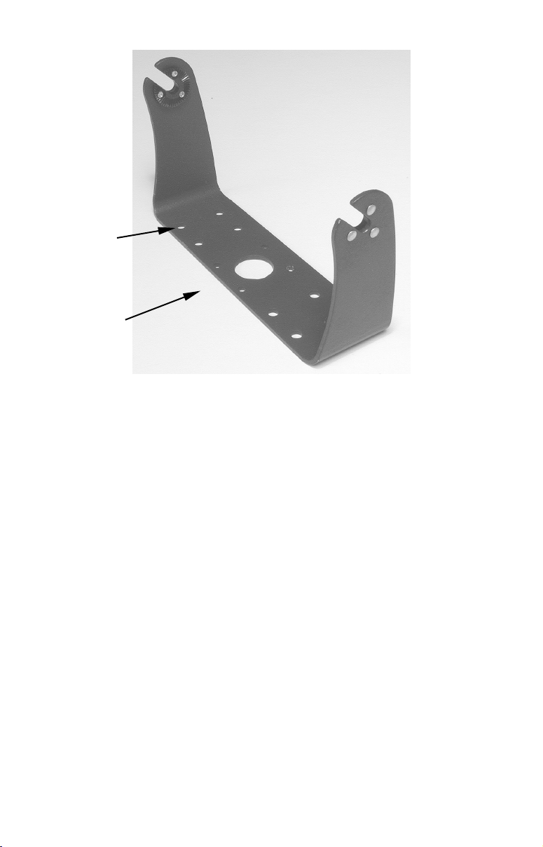
Screw
mounting
hole
Front
Install the gimbal bracket, which looks similar to the one pictured
here. Place the bracket so the arms slope toward the radio's front.
Once a location is determined, use the bracket as a template and mark
the mounting holes. Screw the bracket to the mounting surface. Be sure
to leave enough slack in the cables to allow tilting the unit.
Attach the unit to the gimbal bracket using the supplied gimbal knobs
and washers. Attach the cables and the unit is ready to use.
Antenna
A good antenna installation will optimize the performance of your marine radio. There is no height requirement for antenna installation, but
the higher it is mounted, the better the reception. That's because marine VHF radio signals travel only on a "line of sight" basis. An ideal
installation will give the antenna a clear view of the horizon in all directions.
The antenna may be mounted on a gunwale, rail or on flat surfaces like
a deck, roof or bulkhead. In the case of some sailboats and powerboats,
it may be attached to a mast or mast-like structure.
When installing your VHF marine antenna, be sure to keep it at least
three feet away from any other antenna or metal object. The antenna
also must be installed three feet away from the radio, and at least three
feet from any passengers or crew. Refer to the antenna manufacturer's
instructions for further installation information. You must also make
3

sure your antenna and its installation complies with all local and federal regulations. Never operate your radio unless it is connected to the
antenna.
The antenna must not exceed an antenna gain of 3 decibels (dB). The
antenna cable requires a PL259 connector, and the cable connects at
the back of the radio. For installations less than 25 feet, use RG58 coaxial cable. For installations greater than 25 feet, use RG-8/U coaxial
cable.
WARNINGS:
Using an antenna with gain greater then 3 dB can damage the radio and exceed the safe exposure limits for radio frequency (RF) energy.
Also, the energy from any VHF radio antenna can be
harmful, even one properly rated at 3 dB of gain! Do not
come in contact with the antenna while a transmission is
being sent. Be sure the antenna is installed where it is
separated from people by at least 3 feet of space.
How to Make a Distress Call
Speak slowly, clearly and calmly.
1. Select VHF Channel 16.
2. Press microphone button: "MAYDAY — MAYDAY— MAYDAY."
3. "THIS IS [your ship ID]."
4. "MAYDAY [your ship name]."
5. Tell where you are — what navigational aids or landmarks are near.
6. State the nature of your distress.
7. Give number of persons aboard and condition of any injured.
8. Estimate present seaworthiness of your ship.
9. Briefly describe your ship — meters, type, color, hull.
10. "I WILL BE LISTENING ON CHANNEL 16."
11. End message by saying "THIS IS [ship name/call sign] OVER."
12. Release the PTT key and listen. Someone should answer. If not, repeat call, beginning at Item 3 above.
WARNING
The following types of communication are prohibited by
the FCC: false distress calls; calls to any boat — excluding emergencies and radio tests; calls to or from a vessel
on land and obscene or profane language. Using obscene
or profane language could result in a fine of up to
$10,000.
4
Section 2: Basic Radio Operation
This section addresses the radio’s basic operations, which includes
MMSI (Maritime Mobile Service Identity) number setup. If you already
have your MMSI number programmed into the radio and have a strong
understanding of the radio's basic functions, move on to Section 3:
Advanced Radio Operation.
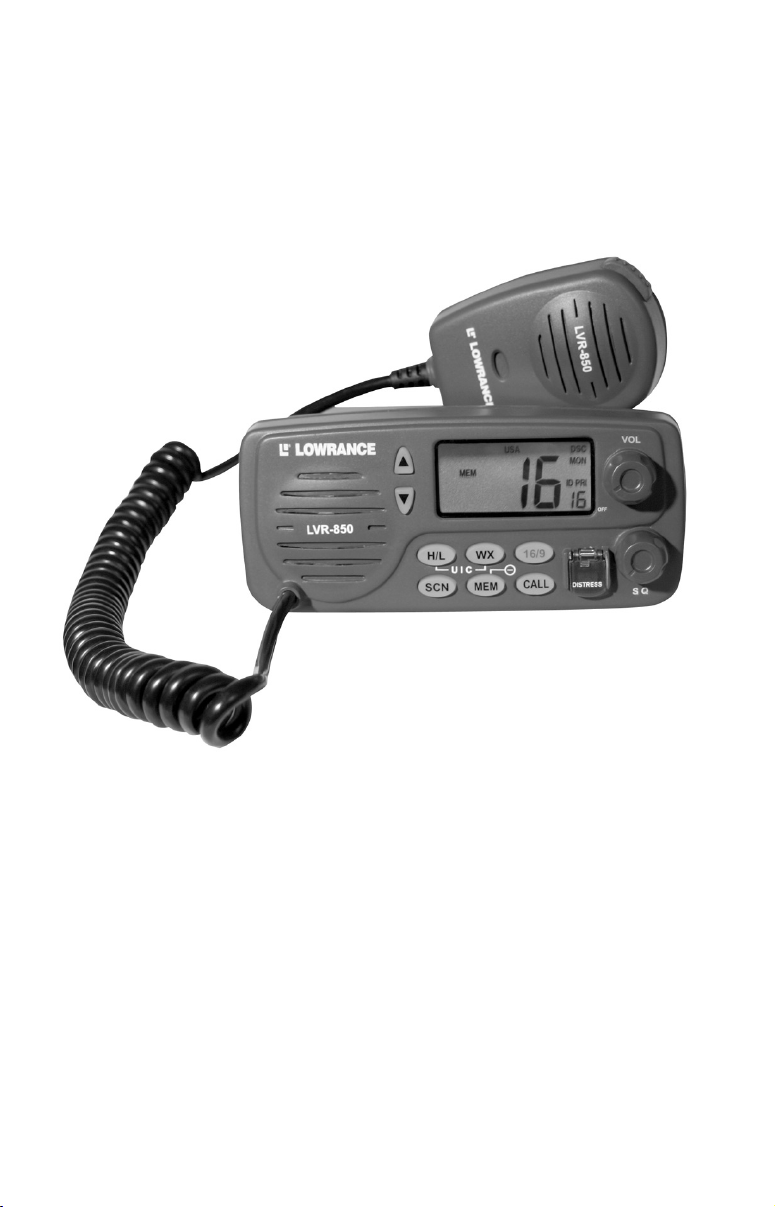
The Lowrance LVR-850 VHF
Marine Radio.
We're going to kick off the operation section with a brief description of
the radio's basic functions. That will be followed by some important information on Digital Selective Calling and basic instructions on how to
make and receive calls.
Using the Keypad
The keypad has eight keys: H/L (Hi/Lo), WX (Weather), 16/9 (Priority
Channels),
down arrow keys. When you press any of the keys a tone will sound. If
you push a key and a 3-beep tone sounds, there is an error or the function is not supported by the radio. You’ll notice several functions require you to hold down a key for a few seconds. In those cases, a single
beep sounds, then, after a few moments, a second beep will be heard to
let you know you have successfully changed the mode.
SCN (Scan), MEM (Memory), CALL (Call) and ↑ ↓, the up-and-
5
Power/Volume
The volume knob at the top right of the radio’s face is used to power up
the LVR 850. Turn the knob clockwise to turn on the radio. The unit
will start on Ch. 2, then switch to Ch. 16, its default priority channel.
Squelch
Squelch, the bottom knob on the radio’s face, helps the unit screen out
radio traffic resulting from signals that are too weak to transmit anything but noise. To adjust the squelch, turn it to the left until noise can
be heard. Turn it back to the right until the noise is eliminated.
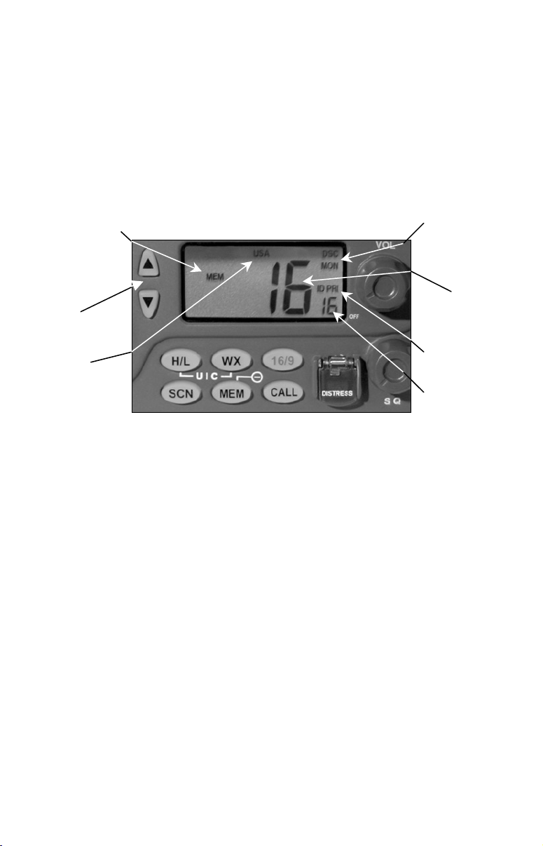
Memory Annunciator
DSC
Monitor
Arrow
Keys
USA
Channel
Bank
Channel
ID
Annunciator
Character
field position
H/L (High/Low)
The
H/L key gives you control over the radio's wattage. The high-end is
25 Watts. The low-end is 1 Watt. If the
LO ANNUNCIATOR is off, the radio
will transmit at 25 Watts.
WX (Weather)
Dark clouds on the horizon? Press the
MODE and get the latest weather information. Use the ↑ ↓ keys to change
the
WX channel.
WX key to enter the WX (WEATHER)
16/9 (Priority Channel)
The
16/9 key is used to switch between priority channels. It also allows
you to exit various operation modes, ignore incoming calls and cancel
outgoing calls.
NOTE
Ch. 16 and Ch. 9 may only be used to make initial contact with a
vessel and nothing more. When there is an emergency, all Distress
calls will be broadcast on Ch. 16.
SCN (Scan)
The
SCN (scan) key allows you to monitor numerous channels at the
same time. Scanning options include:
ALLSCAN.
PRIORITY SCAN, MEMORY SCAN AND
6
 Loading...